Article

Design and Validation of a Portable Handheld Device to Produce Fine Fibers Using Centrifugal Forces

Department of Mechanical Engineering, The University of Texas Rio Grande Valley, 1201 West University Drive, Edinburg, TX 78539, USA
*
Author to whom correspondence should be addressed.
Instruments 2020, 4(3), 27; https://doi.org/10.3390/instruments4030027
Submission received: 28 July 2020 / Revised: 7 September 2020 / Accepted: 9 September 2020 / Published: 14 September 2020

Abstract

:
In the present research project, a novel portable battery-powered handheld device able to produce micron and submicron fibers using centrifugal forces is proposed. The design includes spinnerets with a clamshell configuration with multiple chambers or reservoirs (2, 4, and 8) and different exit orifice diameters (400, 500, 600, and 800 µm). The rotational speed is controlled via an Arduino microcontroller. To validate the design, a series of experiments were conducted and the effect of the orifice diameter, number of chambers, and velocity on the resulting fibers’ diameter and yield was studied. For the experiments, a polymeric solution of Polyvinyl Alcohol (PVA) was prepared. The fiber yield was gravimetrically quantified, and the fiber morphology and diameter were analyzed by means of scanning electron microscopy (SEM). The experimental results showed that spinnerets with an orifice diameter of 500 microns yielded the greatest amount of fibers (0.0777 g). In addition, the number of chambers also affected the amount of fibers produced, and it was determined that the fiber diameter size is dependent on the spinneret speed. Fibers 80 nm in diameter were observed at 6500 rpm.

1. Introduction

In recent history, ultra-thin fibers (UTF) have been considered for several applications due to their unique mechanical properties, high surface area to volume ratio, and potential to resemble cellular topographies [1]. These characteristics are crucial design parameters for engineering materials in applications such as filtration, composite reinforcements, sensors, and tissue scaffolding [2,3,4,5]. Regardless of the current interest in nonwoven UTF (nano, submicron, and single-digit micron fibers), considerable concerns remain about their application due to the lack of a high-yield production method.
Electrospinning is a widely used method to produce UTF; it requires high-voltage electrostatic forces between a polymeric solution that is electrically charged and supplied via a pump and a conductive collector to promote the formation of fibers [6,7,8,9]. Even though electrospinning is a laboratory efficient method to produce fibers, the technique presents several limitations, such as needing a high-voltage power source (5–20 kV), being limited to solvents within a certain range of dielectric constants, having low fiber yield [9], and needing harsh reaction environments. In 2009, Forcespinning® [10,11,12,13,14,15,16,17], was introduced as a new method to produce UTF using centrifugal forces. Forcespinning® is an interesting method to produce UTF, with a considerable increase in yield compared to electrospinning. In this new method, the electrostatic forces used in the electrospinning process to produce UTF are replaced by centrifugal forces. Forcespinning® is a flexible method to produce nanofibers without the mentioned disadvantages faced with the electrospinning method.
Recently, centrifugal electrospinning (CES) has been reported as a promising method to produce nonwoven, ultrafine fiber mats [18]. This new approach integrates the concepts of electrospinning with centrifugal dispersion to produce nanofibers with a high degree of alignment and uniformity at a large scale. Lately, numerous improvements to this technique have been reported for different applications [19,20,21,22,23,24].
In the last two decades, several efforts have been made to create a portable electrospinning device capable of producing nanofibers in-situ. In 2003, Coffee and Pirrie [25,26] developed several portable hand-held, battery-powered electrodispersing devices capable of producing fibers. In 2004, Smith et al. developed battery-powered electrospinning devices [27]. In 2006, Greiner and collaborators released a handheld electrospinning device where standard batteries supplied the high voltage as well [28]. In 2013, Sofokleous et al. reported the design, construction, and testing of a portable handheld electrohydrodynamic (EHD) and multi-needle spray gun capable of producing multifunctional particles and fibers in situ [29]. In 2015, Mouthuy and collaborators proposed a novel, small, battery-operated portable electrospinning apparatus capable of spinning a wide range of polymers into submicron fibers and providing a mesh quality comparable to those produced with benchtop machines [30]. In 2018, Brako et al. reported the design and assembly of a new, miniaturized electrospinner for producing nanofibers at the site of need for drug delivery and wound dressing applications [31].
The main goal of the present research project is to design, build, and evaluate a portable device capable of producing and controlling the deposition of fibers using centrifugal force. The proposed design includes a lightweight and battery-powered portable handheld apparatus that is easy to use and capable of producing fibers of micron, sub-micron, and nano-size diameters.

2. Materials and Methods

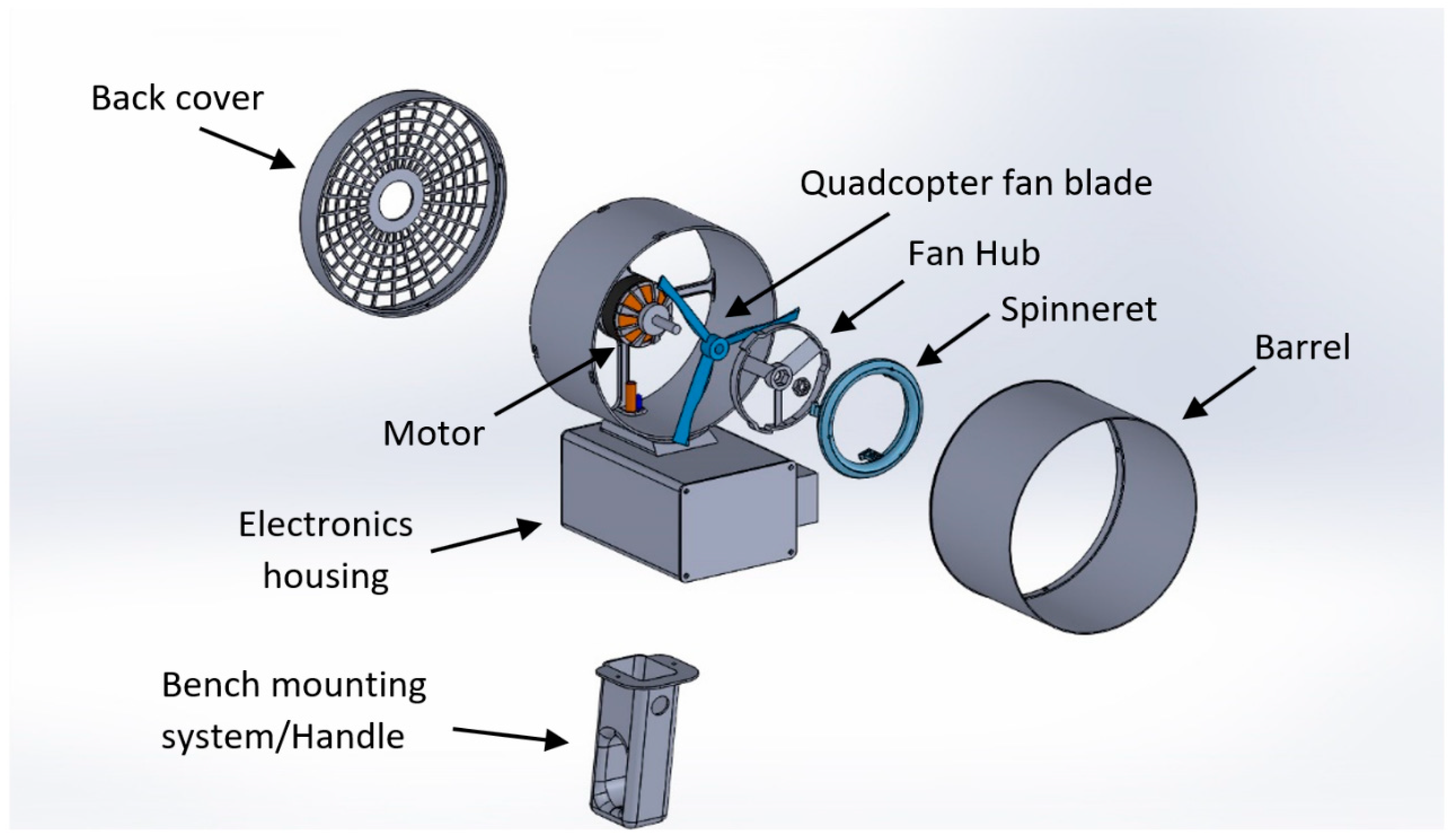
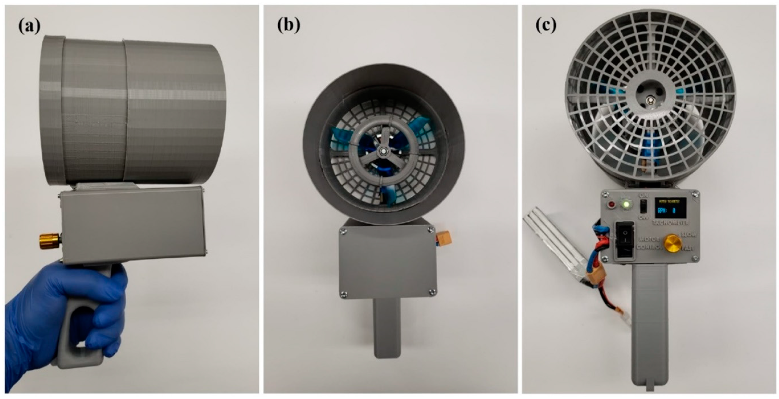
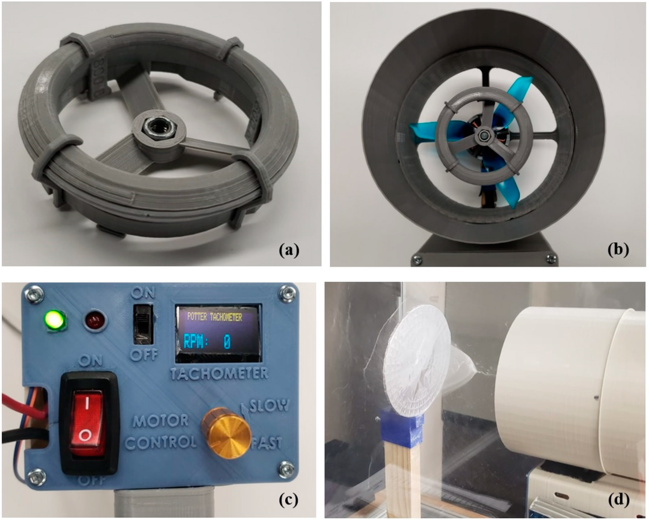
2.1. The Handheld Device (HD)

Forcespinning nanofibers traditionally uses centrifugal force to initiate the growth of a fiber. This process sends the fibers radially along a plane level to the spinneret. For the purpose of a Handheld Device (HD) that can “shoot” fibers, the exiting fibers must be turned perpendicular to this original path. The HD then uses Bernoulli’s principle [32]—that if the relative velocity of air is increased, there will be a pressure drop. This added velocity to the center of the flow draws the fibers into the center of the flow, focusing the fibers on a target 30–60 cm away. The increased velocity is achieved with a small extra fan blade, as well as the shape of the spinneret itself. In order to operate, the HD includes different components, which are described in detail in the following sections. A schematic diagram of the HD with its main components is shown in Figure 1.

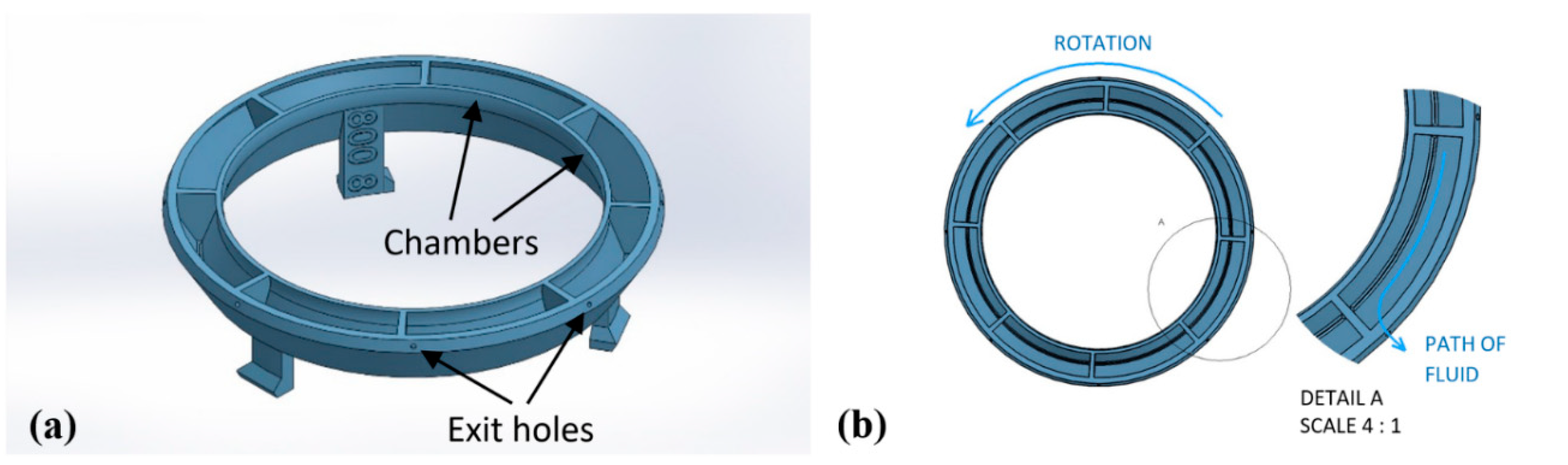
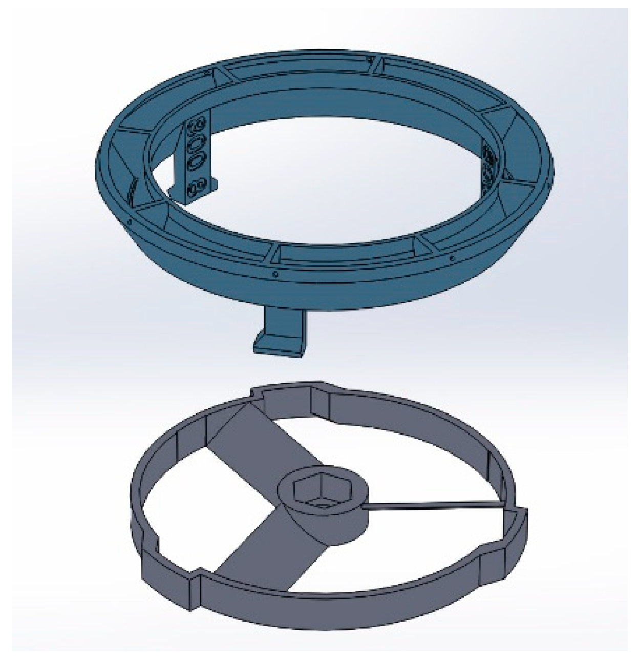
2.1.1. Spinneret and Fan Hub Assembly
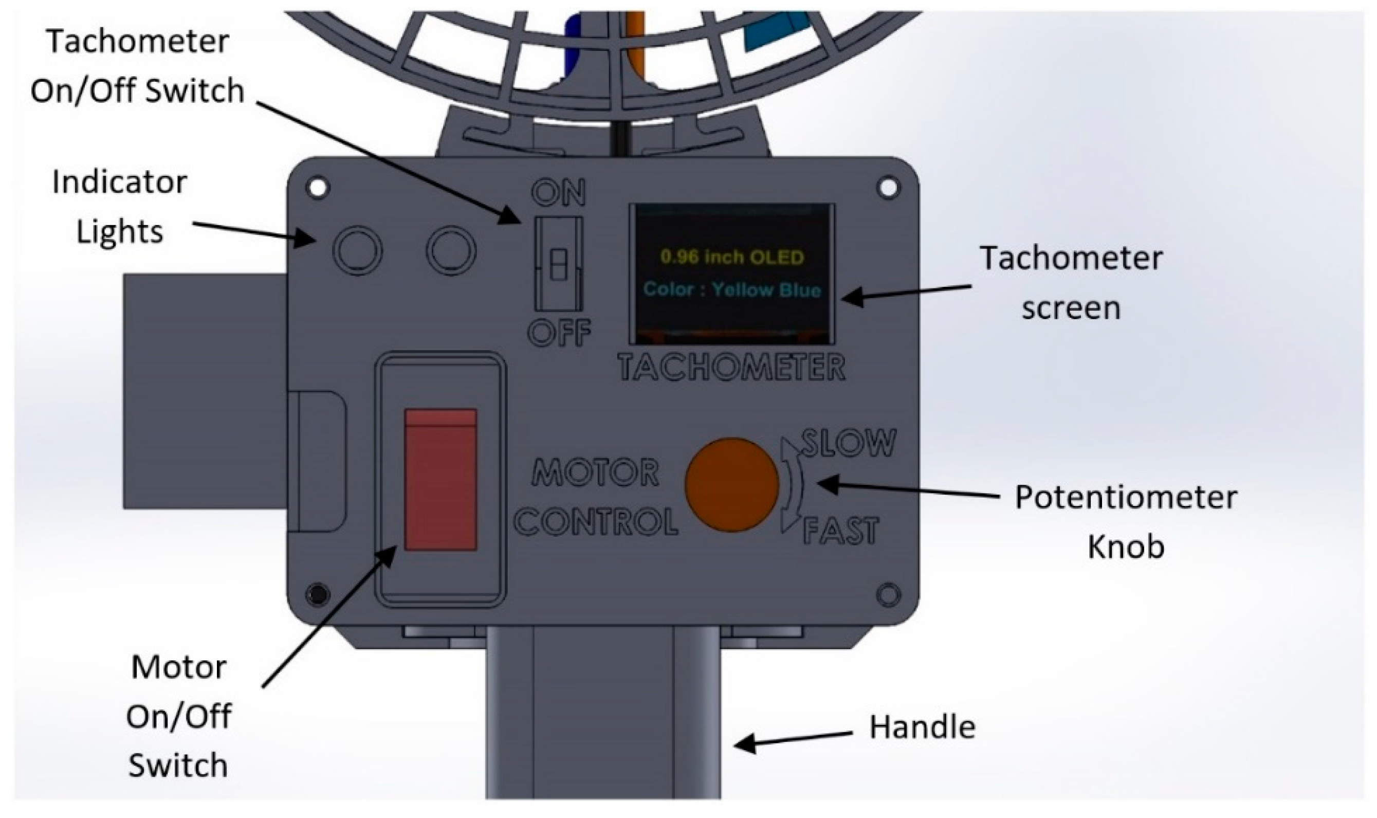
A schematic diagram of the spinneret design is shown in Figure 2. The spinneret is designed to maximize the air velocity in the center of air flow. This is achieved by shaping the cross-section of the spinneret like an air foil, while simultaneously creating a nozzle at the center of air flow. The exit orifices are also angled forward 20 degrees to assist the fibers in making the perpendicular turn from radial travel towards the target, as shown in Figure 2a. A clamshell design of the spinneret was created to allow the easy cleaning and re-use of the spinneret (Figure 2b). The spinneret was split into two pieces and held together with 3 small clips, as shown in Figure 2b,c. The spinnerets were fabricated using a 3D printer including exit holes at various sizes (400 µm–800 µm). The clamshell design in detail including the dimensions is shown in Figure 2d.
Multiple chambers and exit holes were designed and tested (Figure 3a). The number of chambers and exit holes varied from 2 to 8 for the various designs tested. The multiple chambers are necessary in order to properly distribute the solution (fluid) throughout the spinneret while the device is held in a horizontal position (as if to aim the device). This prevents the spinneret from becoming unbalanced during the operation at a high velocity of the device. The exit holes were placed at the rear of each chamber with respect to the rotation of the spinneret. The fluid’s moment of inertia pushes it toward the exit hole at the rear as the spinneret increases the speed of rotation, as shown in Figure 3b.
The fan hub allows for the quick change of the spinneret during use. It also provides an increased velocity in the center of the flow so that the fibers are contained in a “beam” throughout travel to a 20 cm target placed 30–60 cm away from the HD. The fan hub and spinneret are assembled via a twist and lock system, using the rotation of the spinneret to lock the spinneret in place, as shown in Figure 4. This allows the fan hub to be permanently mounted to the motor shaft via a steel nut insert (M6 thread), while simultaneously allowing the spinneret to be switched out with no tools required. The nut and the spinneret are both tightened by the rotation of the motor for safety purposes.

2.1.2. Drive System

The HD is powered by a Lithium Polymer Battery (11.1 V), traditionally used for RC (Remote Contolled) vehicles. The battery weighs 190 g and delivers over 100 h of battery life. This allows for total portability and minimal recharge effort. The motor used is a 600 KV Brushless motor, traditionally used for quadcopters. It delivers up to 430 W of power and weighs only 120 g. A quadcopter fan blade is used, along with a 3D-printed fan blade that is part of the spinneret assembly. The motor is controlled using a 60 Amp Electronic Speed Controller (ESC) and an Arduino Microcontroller. The motor speed is controlled using a potentiometer. The motor speed is displayed on a small OLED screen, using an Arduino-based optical tachometer that is built into the assembly. The tachometer was built using an infrared (IR) sensor VS1838B, an infrared (IR) Emission Tube LED Lamp (Gikfun.com, DongGuan, GuangDong, China), and a 10KOhm resistor. It is powered by the same battery as the motor. A schematic diagram of the drive system is shown in Figure 5.

2.1.3. Housing and Handle

The electronics housing of the HD was fabricated using a 3D printer. The parts were designed in Solidworks and 3D-printed using a Polylactic Acid (PLA) filament at a 200 µm-layer height. The handle of the HD was designed to be replaced by a bench mounting system for consistent results and ease of use during experimentation. A schematic diagram of the housing and handle is shown in Figure 6.
Experimentation was conducted in a test chamber designed for the HD. The test chamber is 61 × 61 × 91 cm and made of polycarbonate. It is designed for safety and visibility. A vacuum hose is connected to the rear of the chamber to remove excess fibers from the air inside the chamber and ensure air quality in the lab. The controls (switch) for the HD was placed outside the chamber so that the device can be started and stopped without opening the chamber.

2.2. HD Performance Experiments

2.2.1. Materials

Polyvinyl Alcohol (PVA) with a molecular weight (MW) of 85,000–124,000, 96% hydrolyzed, was purchased from Kuraray (Kuraray America, Inc., Houston, TX, USA). A polymeric solution with 10 wt % PVA in deionized water was prepared. The PVA and water were placed inside a 20 mL vial along with a stirring magnet. The vial was placed in an oil bath at 75 °C sitting on top of a magnetic stirrer at a speed of 600 rpm. After 60 min, the homogeneous solution was removed from the oil bath and then placed on a magnetic stirrer, and we let the solution stir overnight at an ambient temperature.

2.2.2. Experiments Design

The spinneret orifice diameter, number of chambers, and velocity affects the diameter, length, and yield of the resulting fibers [17]. To better understand how such parameters affect the fibers, a series of experiments were conducted. During these experiments, spinnerets with an orifice diameter ranging from 400 to 800 microns were evaluated. The number of chambers utilized for each spinneret were two, four, and eight, and the rotational speeds used for the different experiments were 4500, 5000, 5500, 6000, and 6500 revolutions per minute (rpm). The fiber production was quantitatively measured on mass basis by means of a Mettler Toledo ME204E analytical balance (Mettler-Toledo LLC, Columbus, OH, USA) to an accuracy of 0.1 mg. The surface morphology and diameter of the spun fibers were analyzed using a field emission scanning electron microscope (FE-SEM) ZEISS SIGMA VP (Carl Zeiss SBE, Thornwood, NY, USA). Prior to observation, each sample was coated with gold using a Denton Vacuum Desk II Sputter Coater (Denton Vacuum LLC, Moorestown, NJ, USA) for 70 s. The average fiber diameter was determined using the ImageJ software (National Institutes of Health (NIH), Bethesda, Rockville, MD, USA).

2.2.3. Experimental Setup

The polymeric solution sample was loaded in a 3 mL syringe attached to an 18-gauge stainless steel needle. A volume of 2 mL of solution was then injected into the 3D-printed spinneret base, being equally distributed among the 2-to-8 chambers of the spinneret. Once the solution was loaded into the spinneret with its cap placed on top, the spinneret was then connected to the fan hub using four 3D-printed clips that cause tightening of all components. Before attaching the loaded spinneret to the HD, the latter was set to the desired speed (4500, 5000, 5500, 6000, or 6500 rpm). The HD was then turned on. Once this process was completed, the control spinneret was removed, and the solution-loaded spinneret assembly was attached to the HD and locked in place. The HD employs centrifugal forces which drives the solution through the spinneret’s orifices, producing nanofibers. The fan creates a perpendicular flow that directs the fibers onto the desired target, creating a nonwoven nanofiber membrane.

3. Results

3.1. Design

The 3D-printed portable handheld device capable of producing fibers using centrifugal forces is shown in Figure 7. A 3D-printed clamshell spinneret assembly connected to the fan hub via 3D-printed clips is shown in Figure 8a. The spinneret assembly mounted on the motor shaft along with the fan blade in the system is shown in Figure 8b. The control panel is located on the back of the PLA housing, as shown in Figure 8c. The spinneret rotational speed can be selected between 0 and 7500 rpm using the potentiometer knob located in the control panel. The speed values are indicated on the OLED screen during use. The drive system components, including the Arduino microcontrollers, the Electronic Speed Controller (ESC), and the battery, are efficiently packed in the PLA housing to minimize the size of the apparatus. Batteries were able to provide enough power for the device to run for about 100 h per charge. Figure 8d shows the HD during operation, where fibers are produced and “shoot” to a desired target, creating a fiber mat.

3.2. HD Performance Experiments

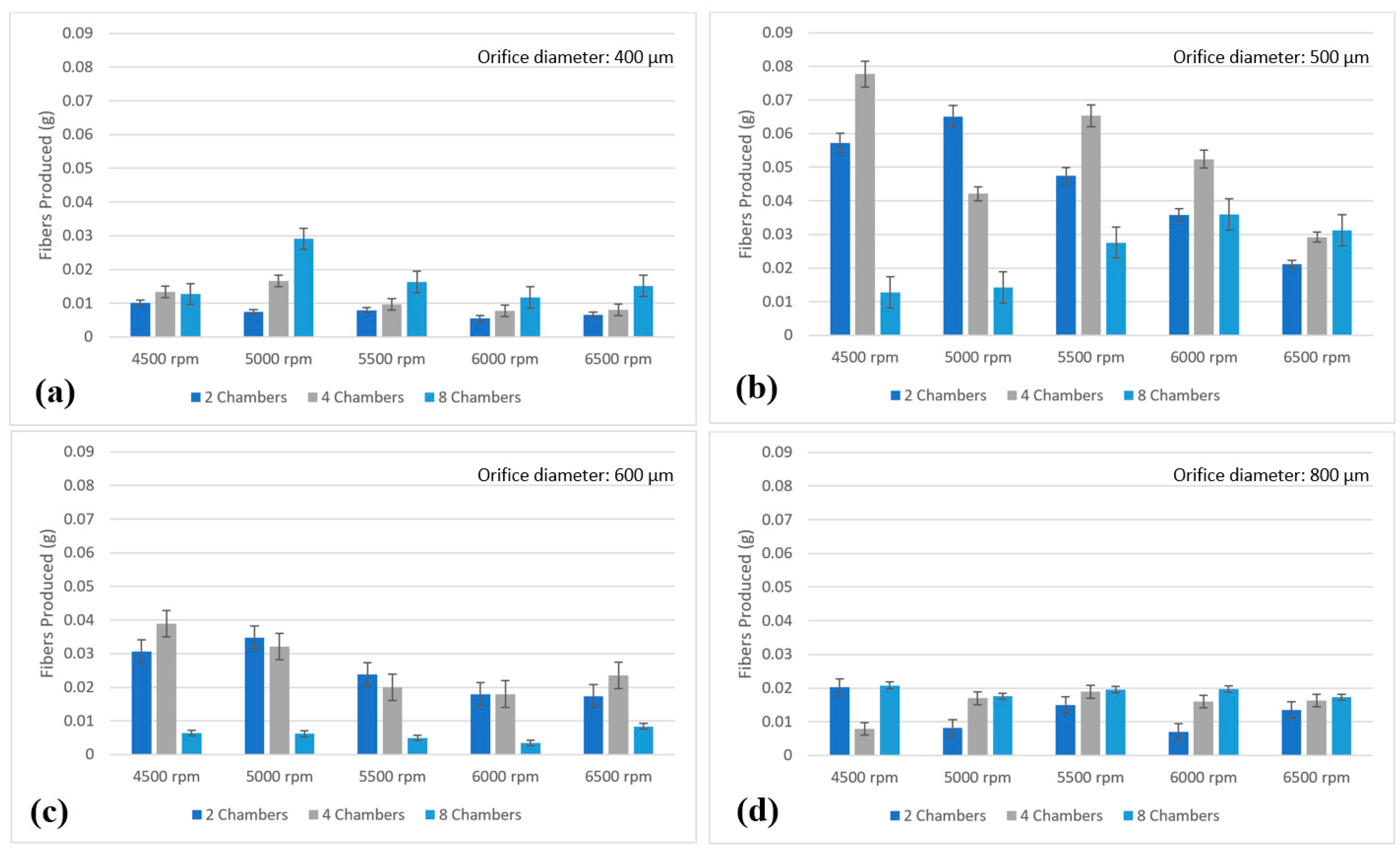
3.2.1. Handheld Device Performance
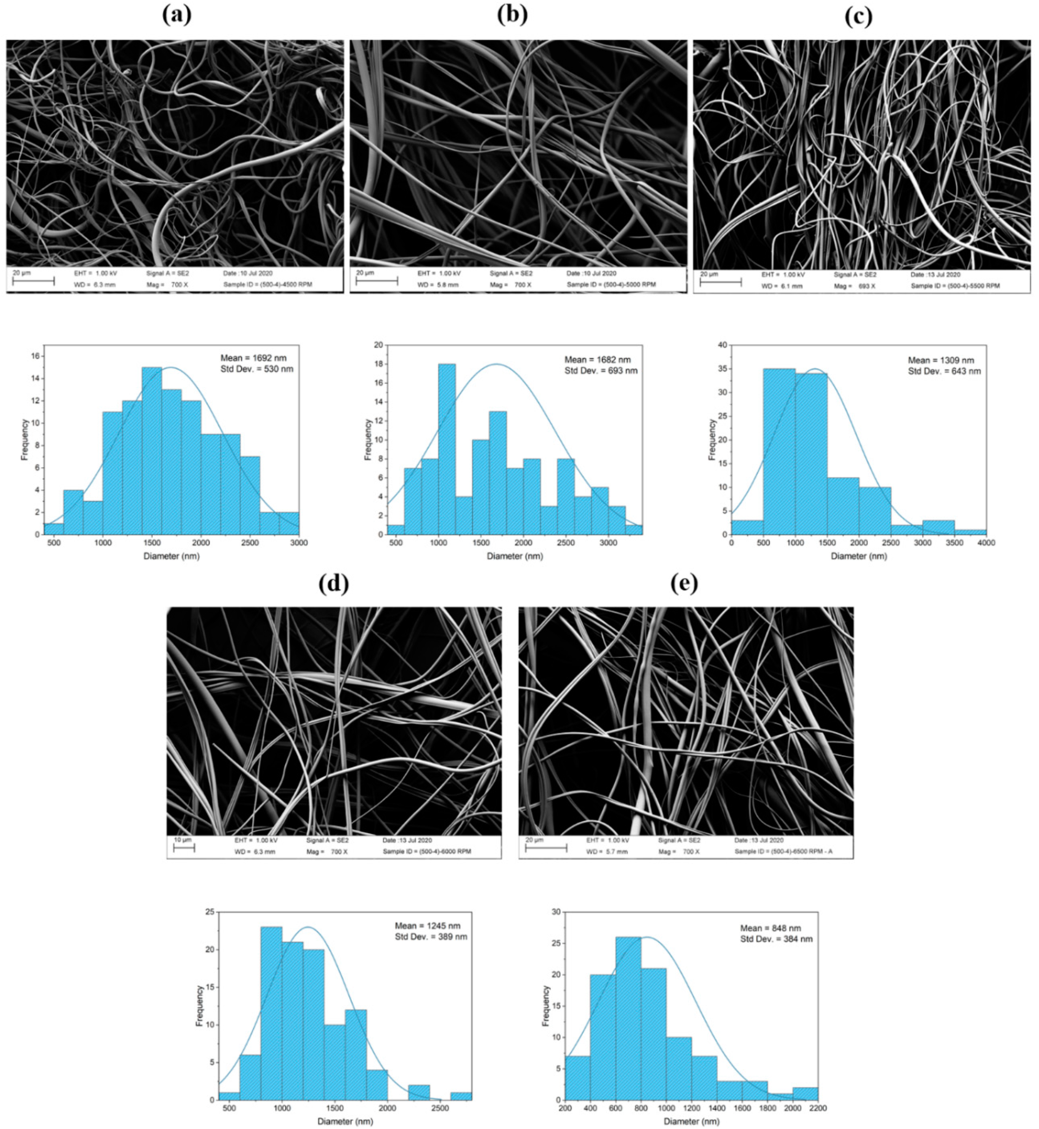
A mass basis quantitatively analysis of fiber production using different rotational speeds (4500, 5000, 5500, 6000, and 6500 rpm) and number of chambers for different exit orifice sizes, is shown in Figure 9. It can be observed that the spinneret with an orifice diameter of 500 microns (Figure 9b) yielded the greatest number of fibers; this is accordance with Mo et al. [33], who found that clogging can be reduced by using a small orifice diameter. The number of chambers also affected the amount of fibers produced, as illustrated in Figure 9. Spinnerets with two and four chambers produced more fibers than spinnerets with eight chambers, but overall four chambers produced more fibers. Considering the flow rate and yield as well as the fiber integrity, a spinneret with four chambers was considered as the optimal system for detailed analysis, and data are presented in Figure 9. It can be observed that the distance traveled by the polymeric solution inside the spinneret before exiting has a strong influence on the yield and yield rate. As the number of chambers increases, the distance traveled becomes smaller. Besides this, the higher the number of chambers and orifices the higher the yield, though this does not necessary imply that long, homogeneous, and continuous fibers are formed for every number of chambers. Spinnerets with two and four chambers do form fibers, while spinnerets with eight chambers have a large presence of beads and droplets due to the small distance traveled by the polymer before exiting the spinneret. On the other hand, the results from varying the spinneret velocity showed that, at 4500 rpm, the highest amount of fiber formation was achieved. From Figure 9, it can be observed that the amount of fibers produced using four chambers and a rotational speed of 4500 rpm was 0.0134, 0.0777, and 0.0389 g for orifice diameters of 400, 500, and 600 microns, respectively. This was also observed in Padron et al. [17], where it was found that high angular velocities limit the amount of fibers produced, since the fibers become too large and jet break-up occurs.

3.2.2. SEM Analysis

The effect of the rotational speed on the fiber diameter was studied from experiments using a spinneret with 500 microns in diameter exit orifices and four chambers at different rotational speeds. Figure 10 depicts SEM images and their corresponding fiber diameter distribution profiles of PVA fibers spun with various rotational speeds (4500, 5000, 5500, 6000, and 6500 rpm). An analysis of the SEM micrographs showed a slight decrease in the fiber diameter with increasing the rotational speed. From Figure 10, it can be observed how the fiber diameters decrease from 1692 nm at 4500 rpm to 1682, 1309, 1245, and 848 nm at 5000, 5500, 6000, and 6500 rpm, respectively.

4. Conclusions

In the present research project, a portable handheld battery-operated device able to produce PVA fibers in the nano, submicron, and single-digit micron scale by means of centrifugal force was successfully designed, built, and evaluated. It should be noted that PVA fibers are able to be obtained, but the goal was set as maximizing the yield with the lowest possible fiber size, though fibers as small as 80 nm were observed. Different spinnerets were designed and evaluated, varying the exit orifice diameters and the number of chambers were the polymeric solution is deposited. The handheld device was capable of producing and depositing PVA fiber mats at a desired target. The fiber production was quantitatively evaluated via gravimetric measurements, and the fiber diameters were measured by SEM. Based on the experimental results, the following conclusions can be drawn:
  • Spinnerets with an orifice diameter of 500 microns yielded the greatest amount of fibers, measured gravimetrically. It was found that clogging can be reduced by using a small orifice diameter.
  • The number of chambers also affected the amount of fibers produced. Spinnerets with two and four chambers produced more fibers than spinnerets with eight chambers.
  • The fiber diameter size is dependent on the spinneret speed. It was found that, as the spinneret rotational speed increases, the fiber diameter decreases.

Author Contributions

Conceptualization, G.P., J.A.O., and K.L.; Data curation, R.B. and J.A.O.; Formal analysis, R.B. and J.A.O.; Investigation, G.P., J.A.O., and K.L.; Methodology, G.P., J.A.O., and K.L.; Project administration, K.L.; Resources, K.L.; Software, R.B. and A.V.; Supervision, K.L.; Validation, R.B., A.V., A.S., H.G., and H.D.L.; Visualization, G.P., J.A.O., and K.L.; Writing—original draft, G.P., R.B., and J.A.O.; Writing—review and editing, G.P., J.A.O., and K.L. All authors have read and agreed to the published version of the manuscript.

Funding

The authors thank the financial support by the National Science Foundation under PREM grant DMR 1523577.

Acknowledgments

The authors would like to acknowledge Manuel Peredo, Rene Galvan, Samya Ahsan, and Pablo Vidal for their support and contributions towards this project.

Conflicts of Interest

The authors declare no conflict of interest.

References

  1. McEachin, Z.; Lozano, K. Production and characterization of polycaprolactone nanofibers via forcespinningTM technology. J. Appl. Polym. Sci. 2012, 126, 473–479. [Google Scholar] [CrossRef]
  2. Yoshimoto, H.; Shin, Y.; Terai, H.; Vacanti, J.P. A biodegradable nanofiber scaffold by electrospinning and its potential for bone tissue engineering. Biomatererials 2003, 24, 2077–2082. [Google Scholar] [CrossRef]
  3. Ito, Y.; Hasuda, H.; Kamitakahara, M.; Ohtsuki, C.; Tanihara, M.; Kang, I.-K.; Kwon, O.H. A composite of hydroxyapatite with electrospun biodegradable nanofibers as a tissue engineering material. J. Biosci. Bioeng. 2005, 100, 43–49. [Google Scholar] [CrossRef]
  4. Graham, K.; Ouyang, M.; Raether, T.; Grafe, T.; McDonald, B.; Knauf, P. Fifteenth Annual Technical Conference & Expo of the American Filtration & Separations Society. Galveston TX 2002, 4, 9–12. [Google Scholar]
  5. Karube, Y.; Kawakami, H. Fabrication of well-aligned electrospun nanofibrous membrane based on fluorinated polyimide. Polym. Adv. Technol. 2010, 21, 861–866. [Google Scholar] [CrossRef]
  6. Li, D.; Xia, Y. Electrospinning of Nanofibers: Reinventing the Wheel? Adv. Mater. 2004, 16, 1151–1170. [Google Scholar] [CrossRef]
  7. Paneva, D.; Bougard, F.; Manolova, N.; Dubois, P.; Rashkov, I. Novel electrospun poly(ε-caprolactone)-based bicomponent nanofibers possessing surface enriched in tertiary amino groups. Eur. Polym. J. 2008, 44, 566–578. [Google Scholar] [CrossRef]
  8. Baji, A.; Mai, Y.-W.; Wong, S.-C.; Abtahi, M.; Chen, P. Electrospinning of polymer nanofibers: Effects on oriented morphology, structures and tensile properties. Compos. Sci. Technol. 2010, 70, 703–718. [Google Scholar] [CrossRef]
  9. Ramakrishna, S. An Introduction to Electrospinning and Nanofibers; World Scientific: Hackensack, NJ, USA, 2005. [Google Scholar]
  10. Lozano, K.; Sarkar, K. Methods and Apparatuses for Making Superfine Fibers. Patent WO2009117356A1, 24 September 2009. [Google Scholar]
  11. Sarkar, K.; Gómez, C.; Zambrano, S.; Ramirez, M.; De Hoyos, E.; Vasquez, H.; Lozano, K. Electrospinning to ForcespinningTM. Mater. Today 2010, 13, 12–14. [Google Scholar] [CrossRef]
  12. Padron, S.; Patlan, R.; Gutiérrez, J.; Santos, N.; Eubanks, T.; Lozano, K. Production and characterization of hybrid BEH-PPV/PEO conjugated polymer nanofibers by forcespinningTM. J. Appl. Polym. Sci. 2012, 125, 3610–3616. [Google Scholar] [CrossRef]
  13. Altecor, A.; Mao, Y.; Lozano, K. large-scale synthesis of tin-doped indium oxide nanofibers using water as solvent. Funct. Mater. Lett. 2012, 5, 1250020. [Google Scholar] [CrossRef]
  14. Rane, Y.; Altecor, A.; Bell, N.S.; Lozano, K. Preparation of Superhydrophobic Teflon® AF 1600 Sub-Micron Fibers and Yarns Using the Forcespinningtm Technique. J. Eng. Fibers Fabr. 2013, 8, 155892501300800420. [Google Scholar] [CrossRef] [Green Version]
  15. Vazquez, B.; Vasquez, H.; Lozano, K. Preparation and characterization of polyvinylidene fluoride nanofibrous membranes by forcespinningTM. Polym. Eng. Sci. 2012, 52, 2260–2265. [Google Scholar] [CrossRef]
  16. Raghavan, B.; Soto, H.; Lozano, K. Fabrication of Melt Spun Polypropylene Nanofibers by Forcespinning. J. Eng. Fibers Fabr. 2013, 8, 155892501300800100. [Google Scholar] [CrossRef] [Green Version]
  17. Padron, S.; Fuentes, A.; Caruntu, D.; Lozano, K. Experimental study of nanofiber production through forcespinning. J. Appl. Phys. 2013, 113, 24318. [Google Scholar] [CrossRef] [Green Version]
  18. Edmondson, D.; Cooper, A.; Jana, S.; Wood, D.; Zhang, M. Centrifugal electrospinning of highly aligned polymer nanofibers over a large area. J. Mater. Chem. 2012, 22, 18646. [Google Scholar] [CrossRef]
  19. Wang, L.; Ahmad, Z.; Huang, J.; Li, J.-S.; Chang, M.-W. Multi-compartment centrifugal electrospinning based composite fibers. Chem. Eng. J. 2017, 330, 541–549. [Google Scholar] [CrossRef]
  20. Wang, L.; Chang, M.-W.; Ahmad, Z.; Zheng, H.; Li, J.-S. Mass and controlled fabrication of aligned PVP fibers for matrix type antibiotic drug delivery systems. Chem. Eng. J. 2017, 307, 661–669. [Google Scholar] [CrossRef]
  21. Wang, L.; Zhang, C.; Wang, H.-M.D.; Ahmad, Z.; Li, J.-S.; Chang, M.-W. High throughput engineering and use of multi-fiber composite matrices for controlled active release. Mater. Today Commun. 2018, 17, 53–59. [Google Scholar] [CrossRef]
  22. Wang, L.; Wang, B.; Ahmad, Z.; Li, J.-S.; Chang, M.-W. Dual rotation centrifugal electrospinning: A novel approach to engineer multi-directional and layered fiber composite matrices. Drug Deliv. Transl. Res. 2018, 9, 204–214. [Google Scholar] [CrossRef]
  23. Liu, Y.; Tan, J.; Yu, S.; Yousefzadeh, M.; Lyu, T.; Jiao, Z.; Li, H.; Ramakrishna, S. High-efficiency preparation of polypropylene nanofiber by melt differential centrifugal electrospinning. J. Appl. Polym. Sci. 2019, 137, 137. [Google Scholar] [CrossRef]
  24. Merchiers, J.; Meurs, W.; Deferme, W.; Peeters, R.; Buntinx, M.; Reddy, N.K. Influence of Polymer Concentration and Nozzle Material on Centrifugal Fiber Spinning. Polymer 2020, 12, 575. [Google Scholar] [CrossRef] [PubMed] [Green Version]
  25. Coffee, R.A. A Dispensing Device and Method for Forming Material. CA Patent 2296334A1, 29 January 1998. [Google Scholar]
  26. Coffee, R.A.; Pirrie, A.B. Dispensing Device. U.S. Patent 6595208B1, 22 July 2003. [Google Scholar]
  27. Smith, D.J.; Reneker, D.H.; McManus, A.T.; Schreuder-Gibson, H.L.; Mello, C.; Sennett, M.S. Electrospun Fibers and an Apparatus Therefor. U.S. Patent 6753454B1, 22 June 2004. [Google Scholar]
  28. Greiner, A.; Wendorff, H.-J. Electrospinning: A Fascinating Method for the Preparation of Ultrathin Fibers. Angew. Chem. Int. Ed. 2007, 46, 5670–5703. [Google Scholar] [CrossRef]
  29. Sofokleous, P.; Stride, E.; Bonfield, W.; Edirisinghe, M. Design, construction and performance of a portable handheld electrohydrodynamic multi-needle spray gun for biomedical applications. Mater. Sci. Eng. C 2013, 33, 213–223. [Google Scholar] [CrossRef]
  30. Mouthuy, P.-A.; Groszkowski, L.; Ye, H. Performances of a portable electrospinning apparatus. Biotechnol. Lett. 2015, 37, 1107–1116. [Google Scholar] [CrossRef] [Green Version]
  31. Brako, F.; Luo, C.J.; Craig, D.Q.M.; Edirisinghe, M. An Inexpensive, Portable Device for Point-of-Need Generation of Silver-Nanoparticle Doped Cellulose Acetate Nanofibers for Advanced Wound Dressing. Macromol. Mater. Eng. 2018, 303, 1700586. [Google Scholar] [CrossRef] [Green Version]
  32. Pritchard, P.J.; Mitchell, J.W. Fox and McDonald’s Introduction to Fluid Mechanics, 9th ed.; Wiley: Hoboken, NJ, USA, 2015. [Google Scholar]
  33. Mo, X.; Xu, C.Y.; Kotaki, M.; Ramakrishna, S. Electrospun P (LLA-CL) nanofiber: A biomimetic extracellular matrix for smooth muscle cell and endothelial cell proliferation. Biomatererials 2004, 25, 1883–1890. [Google Scholar] [CrossRef]
Figure 1. Exploded view of the Handheld Device (HD), showing its main components.
Instruments 04 00027 g001
Figure 2. Spinneret design, showing: (a) the spinneret assembly; (b) clamshell design; (c) spinneret assembly exploded view; and (d) clamshell design in detail, including dimensions.
Instruments 04 00027 g002
Figure 3. Spinneret interior design, showing: (a) multiple chambers and exits and (b) the fiber production process.
Instruments 04 00027 g003
Figure 4. Fan hub assembly.
Instruments 04 00027 g004
Figure 5. Drive system schematic diagram.
Instruments 04 00027 g005
Figure 6. Electronics housing schematic diagram.
Instruments 04 00027 g006
Figure 7. 3D-printed Handheld Device (HD): (a) side view, (b) front view, (c) rear view.
Instruments 04 00027 g007
Figure 8. (a) Spinneret assembly and fan blade mounted on motor shaft, (b) 3D-printed spinneret assembly, (c) control panel, and (d) fiber mat spun with HD.
Instruments 04 00027 g008
Figure 9. Mass basis quantitative analysis of fiber production using different rotational speeds (4500, 5000, 5500, 6000, and 6500 rpm) and number of chambers for different exit orifice diameters: (a) 400, (b) 500, (c) 600, and (d) 800 µm.
Instruments 04 00027 g009
Figure 10. SEM micrographs and corresponding fiber diameter distribution profiles of PVA fibers forcespun with various rotational speeds: (a) 4500, (b) 5000, (c) 5500, (d) 6000, and (e) 6500 rpm.
Instruments 04 00027 g010

