Abstract
This article describes the operation of the near-infrared wavefront sensing based Adaptive Optics (AO) system CIAO. The Coudé Infrared Adaptive Optics (CIAO) system is a central auxiliary component of the Very Large Telescope (VLT) interferometer (VLTI). It enables in particular the observations of the Galactic Center (GC) using the GRAVITY instrument. GRAVITY is a highly specialized beam combiner, a device that coherently combines the light of the four 8-m telescopes and finally records interferometric measurements in the K-band on 6 baselines simultaneously. CIAO compensates for phase disturbances caused by atmospheric turbulence, which all four 8 m Unit Telescopes (UT) experience during observation. Each of the four CIAO units generates an almost diffraction-limited image quality at its UT, which ensures that maximum flux of the observed stellar object enters the fibers of the GRAVITY beam combiner. We present CIAO performance data obtained in the first 3 years of operation as a function of weather conditions. We describe how CIAO is configured and used for observations with GRAVITY. In addition, we focus on the outstanding features of the near-infrared sensitive Saphira detector, which is used for the first time on Paranal, and show how it works as a wavefront sensor detector.
1. Introduction
What does a black hole look like? Do black holes really exist? Questions like these can actually be answered more quantitatively thanks to better and better observations. One of the most interesting observation areas in this context is the center of the Milky Way, where the black hole with the largest angular diameter as seen from Earth is located. The compact radio source Sagittarius A* (SgrA*) at the very center of the Milky Way has been observed over more than five decades (see Genzel et al. [1] and references therein). In 2009, Gillessen et al. [2] published a study which monitored stellar orbits around SgrA* for 16 years. They estimate the mass of SgrA* at about 4 million solar masses. At the distance of the GC of ≈8 kpc, the Schwarzschild radius for a black hole candidate with that mass is 10 as, equivalent to a source diameter of ≈24 million km, or 0.16 astronomical units (AU). Very long baseline radio interferometric measurements, observing the—gravitational lensing magnified—black hole shadow in the emission of SgrA*, give an angular source width of 37 as [3]. This width is actually smaller than the expected width of 5 as because of gravitational lensing. The deviation can be explained using different models for the intrinsic structure of SgrA* [4].
Due to the extremely high extinction in the visible spectral range, the GC can only be examined from the ground at radio and infrared wavelengths. In order to achieve the required spatial resolution in the order of , phase-referenced observations at the VLTI in the infrared spectral range are suitable [5]. The instrument to implement this is called GRAVITY [6] and was proposed in 2005 [7]. GRAVITY had first light with all four 8 m UTs in May 2016 [8].
Recent observations with the GRAVITY instrument allowed for the first time to measure the gravitational redshift in the light of a star orbiting SgrA* and approaching the GC to about 120 AU, i.e., 1400 [9]. Further results show that GRAVITY reaches an astrometric precision close to 10 m as [10,11]. In imaging mode, GRAVITY can achieve angular resolutions with the 4 UTs down to 4 mas (milli-arcsecond).
For the same reasons that the infrared range was used to observe the GC with GRAVITY, the visible AO system MACAO [12], already in operation at the VLTI since 2003, had to be supplemented by an infrared-based AO system. This addition, called CIAO, is discussed in more detail in the following sections.
Although this report is mainly about the AO system performance during GC observations with GRAVITY, there are many other areas in which GRAVITY can be used. This ranges from interferometric Exoplanet observations to mapping the cores of active galactic nuclei [13].
2. Galactic Center Observations with GRAVITY: Requirements for CIAO
GRAVITY is an interferometer that can combine the light of the 4 UTs such that all combinations of 2 UTs, six in total, create interferometric fringes. As described in detail in [14,15,16], after passing the delay lines of the VLTI (see also Figure 1 and Section 3) and the GRAVITY fiber coupler unit, the light of the 4 UTs is fed into single-mode fibers and then further relayed into an integrated optics unit where pairs of UT beams interfere. GRAVITY observes in the near-infrared (NIR) spectral range centered at 2.2 m (K-band, 1.9–2.45 m). The GRAVITY single-mode fibers have a mode field diameter of 7.66 m, sufficiently large to collect the image of a diffraction-limited 2.2 m point source. The fiber coupler injection optics has an f-number of 2.5. This focuses the (nearly) diffraction-limited K-band point spread function (PSF) with a full width at half maximum (FWHM) of 5.5 m into the fiber.

Figure 1.
Schematics of the Very Large Telescope (VLT) interferometer optical path with 2 Unit Telescopes (UTs). The CIAO units are located in the Coudé focal station of the respective telescope. Light from a celestial object is reflected by 9 mirrors (Telescope 2: M1–M9) and is in focus at the mirror M10, located in the Coudé focal station. Star separator units (STS) units select 2 celestial objects within a field of view of 2 arcmin diameter. The light of one object is relayed to CIAO, the light of the second object is relayed to the GRAVITY beam combiner, located in the beam combination lab. Delay lines compensate for optical path length differences between telescopes 1 and 2, which have a distance corresponding to the baseline. Mirror M8 is the deformable mirror shared between MACAO and CIAO. Mirror M9 is a dichroic beam-splitter that reflects infrared light to CIAO and the beam combination lab, visible light is transmitted to MACAO (not shown). Background image: European Southern Observatory (ESO).
The task of CIAO is to create exactly this (nearly) diffraction-limited K-band PSF at the entrance of the fiber coupler inside the GRAVITY beam combiner. The top-level requirements of GRAVITY for CIAO taken from [17] are listed in Table 1.

Table 1.
Performance requirements for Coudé Infrared Adaptive Optics (CIAO) under average atmospheric conditions with a median seeing value at = 0.5 m and at zenith of 0.85 arcsec.
The functional requirements are:
- provide wavefront correction.
- provide near infrared wavefront sensing—allow for off-axis wavefront sensing.
All requirements could be fulfilled with a 9 × 9 Shack-Hartmann wavefront sensor-based AO system running at a speed of 500 Hz. A 320 × 256 pixel HgCdTe avalanche photodiode (APD) array produced by Leonardo S.p.A. in the U.K. was selected as the infrared detector (see Section 4).
3. Overview of the CIAO System
CIAO [17,18,19,20,21] was built to equip the VLTI instrument GRAVITY with infrared-sensitive adaptive optics. GRAVITY’s primary scientific object of investigation is the center of the Milky Way and there especially the massive black hole. The purpose of CIAO is to increase the sensitivity of GRAVITY. This is achieved by compensating for atmospheric turbulence and the resulting almost diffraction-limited image quality of each individual UT. For the GRAVITY instrument, this means a stable injection of light from two adjacent astrophysical objects into the two single-mode input fibers per telescope of GRAVITY. While GRAVITY is located in the beam combination lab (see Figure 1), the four almost identical CIAO units are located inside the Coudé focal stations of the four UTs. Each CIAO unit was designed to fit seamlessly into the VLTI infrastructure. An important element of the existing infrastructure, the 60 actuators bimorph deformable mirror of the MACAO optical AO system, is shared by CIAO.
Figure 1 shows the VLTI optical scheme for the sake of simplicity for two UTs instead of all four UTs. Included are the locations of the STS. Their purpose is to select two small fields of the sky and feed them forward towards the VLTI beam combination lab [22,23]. Details about the STS are shown in Figure 2a. The standard set-up for GC observations is shown in Figure 2b.

Figure 2.
STS optical layout and on-sky set-up for GC observations with GRAVITY. See text for details. (a) Seen perpendicular to the image plane, light from the telescope is reflected on the dichroic beam-splitter M9 towards two mirrors labeled M10. The star separator (STS) unit uses two field select mirrors labeled FSA and FSB to pick the light of two objects A and B, focused on the M10 pair. FSA and FSB are able to scan M10. The light of the two selected objects is then relayed via folding mirrors (labeled FMA and FMB) towards the output beams A and B. Before, however, the beams are compressed via two elliptical mirrors labeled BCA and BCB, and then forwarded via the pupil re-imagers PRA and PRB. Each output beam contains a field of view of about × . Image: ESO; (b) STS set-up for GC observations with GRAVITY. Light from the infrared source IRS7 is transmitted via the STS beam B to the CIAO wavefront sensor. Light from inside the VLTI field of view (red circle) is transmitted via the STS beam A to to GRAVITY beam-combiner.
The CIAO units are designed to deliver nearly diffraction-limited image quality in K-band for each UT. To achieve this, the light of a not too faint point source, i.e., the wavefront sensor (WFS) reference star, with 10 is required. For GC observations the WFS reference star is the bright M-type supergiant IRS7, located about away from SgrA*. In this case, the STS beam B points to IRS7 and CIAO picks this beam using its movable off-axis AO mode selector (AOMS) unit accordingly. The light of the reference star is then relayed and focused via a fold mirror and a parabolic mirror to a focal plane inside the CIAO WFS cryostat (see Figure 3). Alternatively, the GRAVITY beam-combiner and CIAO can share the light of a source. In this case, STS beam A points to the science object and CIAO moves its AOMS on-axis unit to pick beam A. The difference between AOMS off-axis and AOMS on-axis is that the off-axis unit is fully reflective, while the on-axis unit is equipped with a beam splitter. The beam splitter reflects light towards CIAO and transmits light towards the GRAVITY beam-combiner. In the focal area of the CIAO cryostat there is a focal mask and a field lens. The lateral movable field lens together with an achromatic doublet image the pupil (image of the MACAO deformable mirror) through a bandpass filter onto the lenslet array of the Shack-Hartmann sensor.

Figure 3.
Using the adaptive optics (AO) mode selector (AOMS), each CIAO unit can select either STS beam A or B as optical input channel. The light from the selected channel is then relayed via a fold mirror and a parabolic mirror through a de-rotator unit (K-mirror design) into the CIAO wavefront sensor cryostat. The cryogenic part on the lower right side is shown enlarged on the left side in the middle below the label cryogenic environment.
The lenslet array, located in the pupil plane, focuses its images directly on the Saphira detector (see the enlargement of the cryogenic environment in Figure 3). The lateral movable field lens allows us to stabilize the registration between the lenslet array and the deformable mirror in closed-loop operation [24]. The lenslet array is optimized for a wavelength of 2.2 m and a detector pixel size of 24 m. It consists of 9 × 9 square lenses in a square geometry. Each square lens has a size of 192 × 192 and a focal length of 2095 m for a wavelength of 2.2 m. The diffraction-limited K-band PSF of a single lens has an FWHM of ≤26 m, about the size of one detector pixel. The CIAO lenslet array requires exactly 72 × 72 pixels on the detector. Due to the multi-channel readout electronics, CIAO reads a rectangular area of 96 × 72 pixels on the detector. More details about the read-out modes of the Saphira detector are given in Section 4.
Finally, the transmission of all optics up to detector at = 2.2 m for the two operating modes is T = 0.15 for the on-axis configuration and T = 0.32 for the off-axis configuration. These estimates include neither the quantum efficiency of the detector nor the atmospheric transmission.
4. The SAPHIRA Detector
Due to their high frame rates, high sensitivity, low noise, and low dark current, Saphira detectors [25,26,27,28,29,30] have characteristic properties, especially for applications in astronomical adaptive optics, which were not available 10 years ago. The Saphira detector used in CIAO is a 320 × 256 pixel HgCdTe avalanche photodiode array with 24 m square pixels. It is sensitive in the spectral range from 0.8–2.5 m. Unlike other near-infrared arrays, Saphira features a user-adjustable avalanche gain, which multiplies the photon signal but has a minimal impact on the read noise. The CIAO Shack–Hartmann lenslet array, a 9 × 9 square design, is located in the pupil plane such that 68 of the 81 sub-apertures are illuminated (Figure 4). Each sub-aperture covers exactly 8 × 8 pixels on the detector, a total area of 72 × 72 pixels on the detector is evaluated for signal evaluation.

Figure 4.
CIAO lenslet design and footprint on the detector. See text for details. (a) Microscopic image of a CIAO lenslet array with “blue” light reflecting chromium masks, defining the pupil boundaries. The scale is indicated by the red square; (b) Footprint of the illuminated CIAO lenslet on the Saphira detector. Green circle diameter: 72 pixels.
To realize an analog bandwidth for high frame rates, the CIAO Saphira detector array has 32 parallel outputs. To further increase the frame rates of sub-regions, the 32 outputs of the readout integrated circuit (ROIC) are organized to read 32 adjacent pixels of a row at the same time.
To fit the required CIAO lenslet detector region (72 × 72 pixels) with this parallel design, a detector sub-region of 96 × 72 = 6912 pixels has to be readout. Since the readout electronics reads each 320 pixel long detector line in 10 channels of 32 pixels each, 3 channels (96 pixels) must be read out for each 72 CIAO pixels along one line.
Pixel information is digitized using 5 MHz analog to digital converters (ADC). Considering clocking overheads, the time for a non-destructive readout of the CIAO detector sub-region takes 70.6 s [26].
The maximum CIAO loop speed of 500 Hz, therefore, allows us to oversample the detector sub-region up to 28 times using Fowler sampling techniques [26,31]. In particular, this together with a proper electron APD (eAPD) gain setting significantly reduces effective detector readout-noise, down to below 1 electron per pixel. All 4 CIAO Saphira detectors are based on metal–organic vapor phase epitaxy (MOVPE), and have been produced by Leonardo S.p.A. (formerly Selex ES) [32]. The CIAO Saphira detectors are so-called Mark3 devices. It should be noted that the GRAVITY fringe tracker, which compensates the differential piston based on measurements of a brighter off-axis astronomical reference source, uses a Saphira detector as well [33]. Table 2 summarizes the most important CIAO detector characteristics.
Table 2.
CIAO Saphira detector characteristics @ 95 K temperature, or as indicated
We want to emphasize that the readout method is also decisive for the noise behavior of the detector. The CIAO SAPHIRA readout integrated circuit (ROIC) operates the detector on a frame by frame basis, i.e., the complete frame is reset and then at least two frames are readout to obtain a so-called correlated double sampled (CDS) frame. Finally, the two frames are subtracted from each other [26]. This is a well-known technique to reduce various noise sources, including kTC noise, and was already established for CCD detectors readout in the early 1970s [34]. Unfortunately, with the installed ROIC of the CIAO wavefront sensors, the duty cycle is only 50%. A newer version of the ROIC, which can readout and reset the detector on a row by row basis (so-called rolling shutter mode), no longer has this problem [26,28,29].
Additionally, to further reduce readout noise, each pixel can be multiple times converted to digital values and then averaged. As already mentioned, the CIAO window on the detector can be readout 28 times during exposure with an integration time of 2 ms. The point here is that this happens without resetting the pixels. This readout mode is usually called non-destructive readout. In the end, oversampling and subtracting the pixels results in a significant reduction of the readout noise. Such readout schemes are nowadays also used for CCD detectors [35,36].
5. Statistical Review of Three Years of CIAO Operation
In this section, we show the performance results of the CIAO system obtained for GC observations in the years 2017 to 2019. Using the configuration as shown in Figure 2b, the results can be compared quite well, since the same reference star, IRS7, was always observed by CIAO. IRS7 has a K-band magnitude of K = 6.5, which at an AO loop frequency of 500 Hz results in a WFS sub-aperture detector signal per frame of about 1000 photo-electrons. Taking into account the very low readout noise of the detector of about 1 photo-electron per pixel, CIAO can be operated with this configuration in a regime with a high signal-to-noise ratio.
To estimate seeing, recorded time series of CIAO Shack-Hartmann slopes, and DM commands are analyzed during closed-loop operation. The procedure is based on analyzing 60 Zernike coefficients as well as DM command vectors. The Zernike coefficients are created from expanding the Shack-Hartmann slopes into Zernike polynomials. The temporal power spectral density of the Zernike coefficients, as well as the applied DM voltages (commands), were then used to calculate the atmospheric seeing and the pseudo-Strehl numbers (see e.g., Fusco et al., 2004 [37], Snyder et al., 2016 [38]).
Figure 5a compares the CIAO calculated seeing with the seeing recorded by the Paranal Astronomical Site Monitor (ASM) at the time of the CIAO observation. The seeing values are calculated for zenith and for a wavelength of 500 nm. Please note that ASM and CIAO point to different parts on the sky, and thus also different areas of the atmosphere. Figure 5b shows for each CIAO unit the estimated K-band (m) Strehl as a function of the estimated seeing for Galactic Center observations in the years 2017 to 2019. This can be compared to our simulation result for GC observations [17,20], which calculated a K-band Strehl of 0.38 at a zenith distance of 30 degrees, and a seeing (at m) of 0.93 arcsec. See pushpin in Figure 5b. In general, the results obtained are slightly better than expected from our simulation.
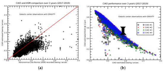
Figure 5.
Estimated CIAO seeing and CIAO performance results for 3 years of Galactic Center (GC) observations with GRAVITY. (a) CIAO estimated seeing vs recorded Paranal Astronomical Site Monitor (ASM) seeing; (b) CIAO estimated K-band Strehl number vs CIAO estimated seeing (at m and air mass along the line of sight). The pushpin points to our simulation result.
Furthermore, there are some “failures” visible, which are usually based on technical problems and sometimes also on wrong software settings. Although, in most of these cases an improvement was still achieved (note that the natural Strehl at m even for an excellent Seeing of is only approx. 0.02). Without AO, on average less than 1% of the stellar flux can be coupled into the single-mode fiber of the GRAVITY beam combiner.
Besides the pure Strehl performance, the residual image jitter is an important factor to judge the efficiency of feeding light into the beam combiner fibers. Figure 6 and Figure 7 show exemplarily for one night the residual image motion (jitter) over a period of 150 s of all 4 CIAO units obtained for GC observations. In general, we find that the 1-axis residual image motion jitter is in the range 5–10 mas rms. This is well within the targeted range according to Table 1. These measurements were taken with the VLTI infrared camera (IRIS) and 70 ms integration time. IRIS observed a field around the GC, and one star of the IRS16 sources was used for the analysis.

Figure 6.
Residual image motion jitter along the x-axis (x_cen) over 150 s observation of the GC. The title line shows the calculated rms value (RMS_cen_x) in mas.

Figure 7.
Residual image motion jitter along the y-axis (y_cen) over 150 s observation of the GC. The title line shows the calculated rms value (RMS_cen_y) in mas.
As shown in Figure 8, GC observers had on average a very respectable AO performance in the years 2017–2019. The achieved median Strehl number in K-band was above 0.6 and clearly met the Table 1 requirement.

Figure 8.
CIAO Strehl histogram for 3 years of GC observations with GRAVITY.
6. Summary
CIAO is an adaptive optics system, which in combination with the GRAVITY instrument, allows efficient interferometric observations with four 8 m telescopes. In the three years studied, typically all CIAO units achieved a median K-band Strehl number of 0.67. The first years of observations with CIAO and GRAVITY at the Paranal Observatory were very successful. More than 30 scientific papers have been published by the GRAVITY collaboration since 2017. We anticipate that this will continue.
Author Contributions
Conceptualization, S.H. and W.B.; methodology S.H. and W.B.; project administration S.S.; investigation, S.H., W.B., S.S., M.K., J.P., P.B., H.B., C.D., F.D.-S., F.E., G.F., Z.H., J.K., E.M., L.P., J.W., G.Z. and G.C.; writing—review and editing, S.H. and W.B. All authors have read and agreed to the published version of the manuscript.
Funding
This research received no external funding.
Conflicts of Interest
The authors declare no conflict of interest.
References
- Genzel, R.; Eisenhauer, F.; Gillessen, S. The Galactic Center massive black hole and nuclear star cluster. Rev. Mod. Phys. 2010, 82, 3121–3195. [Google Scholar] [CrossRef]
- Gillessen, S.; Eisenhauer, F.; Trippe, S.; Alexander, T.; Genzel, R.; Martins, F.; Ott, T. Monitoring Stellar Orbits Around the Massive Black Hole in the Galactic Center. Astrophys. J. 2009, 692, 1075–1109. [Google Scholar] [CrossRef]
- Doeleman, S.S.; Weintroub, J.; Rogers, A.E.; Plambeck, R.; Freund, R.; Tilanus, R.P.; Friberg, P.; Ziurys, L.M.; Moran, J.M.; Corey, B.; et al. Event-horizon-scale structure in the supermassive black hole candidate at the Galactic Centre. Nature 2008, 455, 78–80. [Google Scholar] [CrossRef] [PubMed]
- Lu, R.S.; Krichbaum, T.P.; Roy, A.L.; Fish, V.L.; Doeleman, S.S.; Johnson, M.D.; Akiyama, K.; Psaltis, D.; Alef, W.; Asada, K.; et al. Detection of Intrinsic Source Structure at 3 Schwarzschild Radii with Millimeter-VLBI Observations of SAGITTARIUS A*. Astrophys. J. 2018, 859, 60. [Google Scholar] [CrossRef]
- Woillez, J.; Darré, P.; Egner, S.; Gonté, F.; Haubois, X.; Mérand, A.; Schuhler, N.; Abad, J.A.; Abuter, R.; Aller-Carpentier; et al. VLTI status update: Three years into the second generation. Proc. SPIE 2018, 10701, 1070103. [Google Scholar] [CrossRef]
- Eisenhauer, F.; Perrin, G.; Brandner, W.; Straubmeier, C.; Perraut, K.; Amorim, A.; Schöller, M.; Gillessen, S.; Kervella, P.; Benisty, M.; et al. GRAVITY: Observing the Universe in Motion. Messenger 2011, 143, 16–24. [Google Scholar]
- Eisenhauer, F.; Perrin, G.; Rabien, S.; Eckart, A.; Lena, P.; Genzel, R.; Abuter, R.; Paumard, T.; Brandner, W. GRAVITY: The AO-Assisted, Two-Object Beam-Combiner Instrument for the VLTI. In The Power of Optical/IR Interferometry: Recent Scientific Results and 2nd Generation; Richichi, A., Delplancke, F., Paresce, F., Chelli, A., Eds.; Springer: Berlin/Heidelberg, Germany, 2008; p. 431. [Google Scholar] [CrossRef]
- Gravity Collaboration; Accardo, M.; Amorim, A.; Anugu, N.; Avila, G.; Azouaoui, N.; Benisty, M.; Berger, J.P.; Blind, N.; Bonnet, H.; et al. First light for GRAVITY: Phase referencing optical interferometry for the Very Large Telescope Interferometer. Astron. Astrophys. 2017, 602, A94. [Google Scholar] [CrossRef]
- Gravity Collaboration; Abuter, R.; Amorim, A.; Anugu, N.; Bauböck, M.; Benisty, M.; Berger, J.P.; Blind, N.; Bonnet, H.; Brandner, W.; et al. Detection of the gravitational redshift in the orbit of the star S2 near the Galactic centre massive black hole. Astron. Astrophys. 2018, 615, L15. [Google Scholar] [CrossRef]
- Gravity Collaboration; Abuter, R.; Amorim, A.; Bauböck, M.; Berger, J.P.; Bonnet, H.; Brandner, W.; Clénet, Y.; Coudé Du Foresto, V.; de Zeeuw, P.T.; et al. Detection of orbital motions near the last stable circular orbit of the massive black hole SgrA*. Astron. Astrophys. 2018, 618, L10. [Google Scholar] [CrossRef]
- Gravity Collaboration; Abuter, R.; Amorim, A.; Bauböck, M.; Berger, J.P.; Bonnet, H.; Brandner, W.; Clénet, Y.; Coudé Du Foresto, V.; de Zeeuw, P.T.; et al. Spatially resolved rotation of the broad-line region of a quasar at sub-parsec scale. Nature 2018, 563, 657–660. [Google Scholar] [CrossRef]
- Schöller, M. The Very Large Telescope Interferometer: Current facility and prospects. New Astron. Rev. 2007, 51, 628–638. [Google Scholar] [CrossRef]
- GRAVITY Collaboration; Abuter, R.; Accardo, M.; Adler, T.; Amorim, A.; Anugu, N.; Ávila, G.; Bauböck, M.; Benisty, M.; Berger, J.-P.; et al. GRAVITY Science. Messenger 2019, 178, 19–49. [Google Scholar] [CrossRef]
- Yang, P.; Hippler, S.; Deen, C.P.; Brandner, W.; Clénet, Y.; Henning, T.; Huber, A.; Kendrew, S.; Lenzen, R.; Pfuhl, O.; et al. Characterization of the transmitted near-infrared wavefront error for the GRAVITY/VLTI Coudé Infrared Adaptive Optics System. Opt. Express 2013, 21, 9069. [Google Scholar] [CrossRef] [PubMed]
- Pfuhl, O.; Haug, M.; Eisenhauer, F.; Kellner, S.; Haussmann, F.; Perrin, G.; Gillessen, S.; Straubmeier, C.; Ott, T.; Rousselet-Perraut, K.; et al. The fiber coupler and beam stabilization system of the GRAVITY interferometer. Proc. SPIE 2014, 9146, 914623. [Google Scholar] [CrossRef]
- Perraut, K.; Jocou, L.; Berger, J.P.; Chabli, A.; Cardin, V.; Chamiot-Maitral, G.; Delboulbé, A.; Eisenhauer, F.; Gambérini, Y.; Gillessen, S.; et al. Single-mode waveguides for GRAVITY. I. The cryogenic 4-telescope integrated optics beam combiner. Astron. Astrophys. 2018, 614, A70. [Google Scholar] [CrossRef]
- Clénet, Y.; Rousset, G.; Eisenhauer, F.; Gillessen, S.; Perrin, G.; Amorim, A.; Brandner, W.; Perraut, K.; Straubmeier, C. Dimensioning the Gravity adaptive optics wavefront sensor. Proc. SPIE 2010, 7736, 7364A. [Google Scholar] [CrossRef]
- Scheithauer, S.; Brandner, W.; Deen, C.; Adler, T.; Bonnet, H.; Bourget, P.; Chemla, F.; Clenet, Y.; Delplancke, F.; Ebert, M.; et al. CIAO: Wavefront sensors for GRAVITY. Proc. SPIE 2016, 9909, 99092L. [Google Scholar] [CrossRef]
- Deen, C.; Kolb, J.; Oberti, S.; Bonnet, H.; Müller, E.; Hubert, Z.; Zins, G.; Delplancke, F.; Haguenauer, P.; Pettazzi, L.; et al. System tests and on-sky commissioning of the GRAVITY-CIAO wavefront sensors. Proc. SPIE 2016, 9909, 99092M. [Google Scholar] [CrossRef]
- Kendrew, S.; Hippler, S.; Brandner, W.; Clénet, Y.; Deen, C.; Gendron, E.; Huber, A.; Klein, R.; Laun, W.; Lenzen, R.; et al. GRAVITY Coudé Infrared Adaptive Optics (CIAO) system for the VLT Interferometer. Proc. SPIE 2012, 8446, 84467W. [Google Scholar] [CrossRef]
- Hippler, S.; Brandner, W.; Clénet, Y.; Hormuth, F.; Gendron, E.; Henning, T.; Klein, R.; Lenzen, R.; Meschke, D.; Naranjo, V.; et al. Near-infrared wavefront sensing for the VLT interferometer. Proc. SPIE 2008, 7015, 701555. [Google Scholar] [CrossRef]
- Nijenhuis, J.R.; Giesen, P.T.M. A major step forward back in time with the ESO Star Separator system. Proc. SPIE 2005, 5877, 24–30. [Google Scholar] [CrossRef]
- Nijenhuis, J.; Visser, H.; de Man, H.; Dekker, B.; Mekking, J.; Kamphues, F. Simultaneous observation of two stars using the PRIMA Star Separator. Proc. SPIE 2008, 7013, 70133F. [Google Scholar] [CrossRef]
- Dai, X.; Hippler, S.; Gendron, E. Experiments of two pupil lateral motion tracking algorithms using a Shack-Hartmann sensor. J. Mod. Opt. 2017, 64, 127–137. [Google Scholar] [CrossRef]
- Finger, G.; Baker, I.; Alvarez, D.; Ives, D.; Mehrgan, L.; Meyer, M.; Stegmeier, J.; Weller, H.J. SAPHIRA detector for infrared wavefront sensing. Proc. SPIE 2014, 9148, 914817. [Google Scholar] [CrossRef]
- Finger, G.; Baker, I.; Alvarez, D.; Dupuy, C.; Ives, D.; Meyer, M.; Mehrgan, L.; Stegmeier, J.; Weller, H.J. Sub-electron read noise and millisecond full-frame readout with the near infrared eAPD array SAPHIRA. Proc. SPIE 2016, 9909, 990912. [Google Scholar] [CrossRef]
- Mehrgan, L.H.; Finger, G.; Eisenhauer, F.; Panduro, J. GRAVITY detector systems. Proc. SPIE 2016, 9907, 99072F. [Google Scholar] [CrossRef]
- Atkinson, D.E.; Hall, D.N.; Baker, I.M.; Goebel, S.B.; Jacobson, S.M.; Lockhart, C.; Warmbier, E.A. Next-generation performance of SAPHIRA HgCdTe APDs. Proc. SPIE 2016, 9915, 99150N. [Google Scholar] [CrossRef]
- Finger, G.; Baker, I.; Alvarez, D.; Eisenhauer, F.; Hechenblaikner, G.; Ives, D.; Mehrgan, L.; Meyer, M.; Stegmeier, J.; Weller, H.J. On-sky performance verification of near infrared eAPD technology for wavefront sensing at ground based telescopes, demonstration of e-APD pixel performance to improve the sensitivity of large science focal planes and possibility to use this technology in space. Proc. SPIE 2019, 11180, 111806L. [Google Scholar] [CrossRef]
- Goebel, S.B.; Jacobson, S.M.; Lockhart, C.; Warmbier, E.A. Overview of the SAPHIRA detector for adaptive optics applications. J. Astron. Telesc. Instrum. Syst. 2018, 4, 026001. [Google Scholar] [CrossRef]
- Fowler, A.M.; Gatley, I. Demonstration of an Algorithm for Read-Noise Reduction in Infrared Arrays. Astrophys. J. 1990, 353, L33. [Google Scholar] [CrossRef]
- Baker, I.; Maxey, C.; Hipwood, L.; Barnes, K. Leonardo (formerly Selex ES) infrared sensors for astronomy: Present and future. Proc. SPIE 2016, 9915, 991505. [Google Scholar] [CrossRef]
- Lacour, S.; Dembet, R.; Abuter, R.; Fédou, P.; Perrin, G.; Choquet, É.; Pfuhl, O.; Eisenhauer, F.; Woillez, J.; Cassaing, F.; et al. The GRAVITY fringe tracker. Astron. Astrophys. 2019, 624, A99. [Google Scholar] [CrossRef]
- White, M.H.; Lampe, D.R.; Blaha, F.C.; Mack, I.A. Characterization of surface channel CCD image arrays at low light levels. IEEE J. Solid-State Circuits 1974, 9, 1–12. [Google Scholar] [CrossRef]
- Alessandri, C.; Abusleme, A.; Guzman, D.; Passalacqua, I.; Alvarez-Fontecilla, E.; Guarini, M. Optimal CCD readout by digital correlated double sampling. Mon. Not. R. Astron. Soc. 2016, 455, 1443–1450. [Google Scholar] [CrossRef]
- Cruz de la Torre, C.; de Vicente Albendea, J. Digital correlated double sampling CCD readout characterization. Proc. SPIE 2018, 10709, 1070920. [Google Scholar] [CrossRef]
- Fusco, T.; Ageorges, N.; Rousset, G.; Rabaud, D.; Gendron, E.; Mouillet, D.; Lacombe, F.; Zins, G.; Charton, J.; Lidman, C.; et al. NAOS performance characterization and turbulence parameters estimation using closed-loop data. Proc. SPIE 2004, 5490, 118–129. [Google Scholar] [CrossRef]
- Snyder, A.; Srinath, S.; Macintosh, B.; Roodman, A. Temporal characterization of Zernike decomposition of atmospheric turbulence. Proc. SPIE 2016, 9906, 990642. [Google Scholar] [CrossRef]


© 2020 by the authors. Licensee MDPI, Basel, Switzerland. This article is an open access article distributed under the terms and conditions of the Creative Commons Attribution (CC BY) license (http://creativecommons.org/licenses/by/4.0/).