Review

Electroluminescence and Electron Avalanching in Two-Phase Detectors

by
Alexey Buzulutskov
1,2
1
Budker Institute of Nuclear Physics, 630090 Novosibirsk, Russia
2
Novosibirsk State University, 630090 Novosibirsk, Russia
Instruments 2020, 4(2), 16; https://doi.org/10.3390/instruments4020016
Submission received: 7 May 2020 / Revised: 5 June 2020 / Accepted: 10 June 2020 / Published: 18 June 2020
(This article belongs to the Special Issue Light Production and Detection in Noble Liquid Detectors)

Abstract

:
Electroluminescence and electron avalanching are the physical effects used in two-phase argon and xenon detectors for dark matter searches and neutrino detection, to amplify the primary ionization signal directly in cryogenic noble-gas media. We review the concepts of such light and charge signal amplification, including a combination thereof, both in the gas and in the liquid phase. Puzzling aspects of the physics of electroluminescence and electron avalanching in two-phase detectors are explained, and detection techniques based on these effects are described.

1. Introduction

The ultimate goal for liquid noble-gas detectors is the development of large-volume detectors of superior sensitivity for rare-event experiments. A typical deposited energy in such experiments might be rather low: of the order of 0.1 keV in coherent neutrino-nucleus scattering experiments, 1–100 keV in those of dark matter search and ≥100 keV in those of astrophysical and accelerator neutrino detection. Accordingly, the primary ionization and scintillation signals produced by a particle in noble-gas liquid have to be amplified in dense noble-gas media at cryogenic temperatures.
The idea of two-phase detectors [1] is based on the requirement of amplification of such weak signals (see reviews [2,3]). In particular, the scattered particle produces in the liquid phase two types of signals: that of primary scintillation recorded promptly (S1 signal) and that of primary ionization recorded with delay (S2 signal). While for the readout of the S1 signal it is sufficient to use optical devices such as photomultiplier tubes (PMTs) and silicon photomultipliers (SiPMs) having their own electronic amplification, to record the S2 signal, one has to amplify it in the detection medium directly (in case of the low deposited energy). In two-phase detectors this is done in the following way: the primary ionization electrons, after drifting in the liquid phase, are emitted into the gas phase where their (S2) signal is amplified. In “classic” two-phase detectors, the way to amplify the S2 signal is provided by electroluminescence (secondary scintillation) produced by drifting electrons under high electric fields. The second possible way to amplify the S2 signal is that of electron avalanching (electron multiplication) at high electric fields. In the following, we refer to these two ways of amplification as those of light and charge signal amplification, respectively.
This review is dedicated to the issue of S2 signal amplification. We review all known concepts of light and charge signal amplification (i.e., those based on electroluminescence and electron avalanching in cryogenic noble-gas media), including a combination thereof, both in the gas and in the liquid phase. We explain puzzling aspects of the physics of electroluminescence and electron avalanching in two-phase detectors and describe detection techniques based on these effects.

2. Basic Concepts of Signal Amplification in Two-Phase Detectors

Many methods for light and charge signal amplification in two-phase detectors have been proposed, and some of these are described in reviews [2,3,4,5,6]. Among this variety, two basic concepts can be distinguished, that most other concepts come from.
The basic concept of light signal amplification is that of the “classic” two-phase detector (see [3]); it is provided by the effect of proportional electroluminescence (EL): see Figure 1. Here each drifting electron of the ionization (S2) signal emits light in the EL gap under high electric field, the light intensity being roughly proportional to the electric field. This concept splits into two sub-concepts: with indirect and direct optical readout. For the former, the optical readout goes via a wavelength shifter (WLS).
The basic concept of charge signal amplification in two-phase detectors is that of using a gas electron multiplier (GEM)-like structure in the gas phase that provides electron avalanching within the GEM holes at cryogenic temperatures: see Figure 2 and review [4].
In Section 3, Section 4, Section 5 and Section 6, we describe in detail the physics and state-of-the-art of these basic concepts, as well as consider other (most developed) concepts of signal amplification in cryogenic noble-gas media.

3. Light Signal Amplification in the Gas Phase of a Two-Phase Detector, Using Proportional Electroluminescence

3.1. Three EL Mechanisms

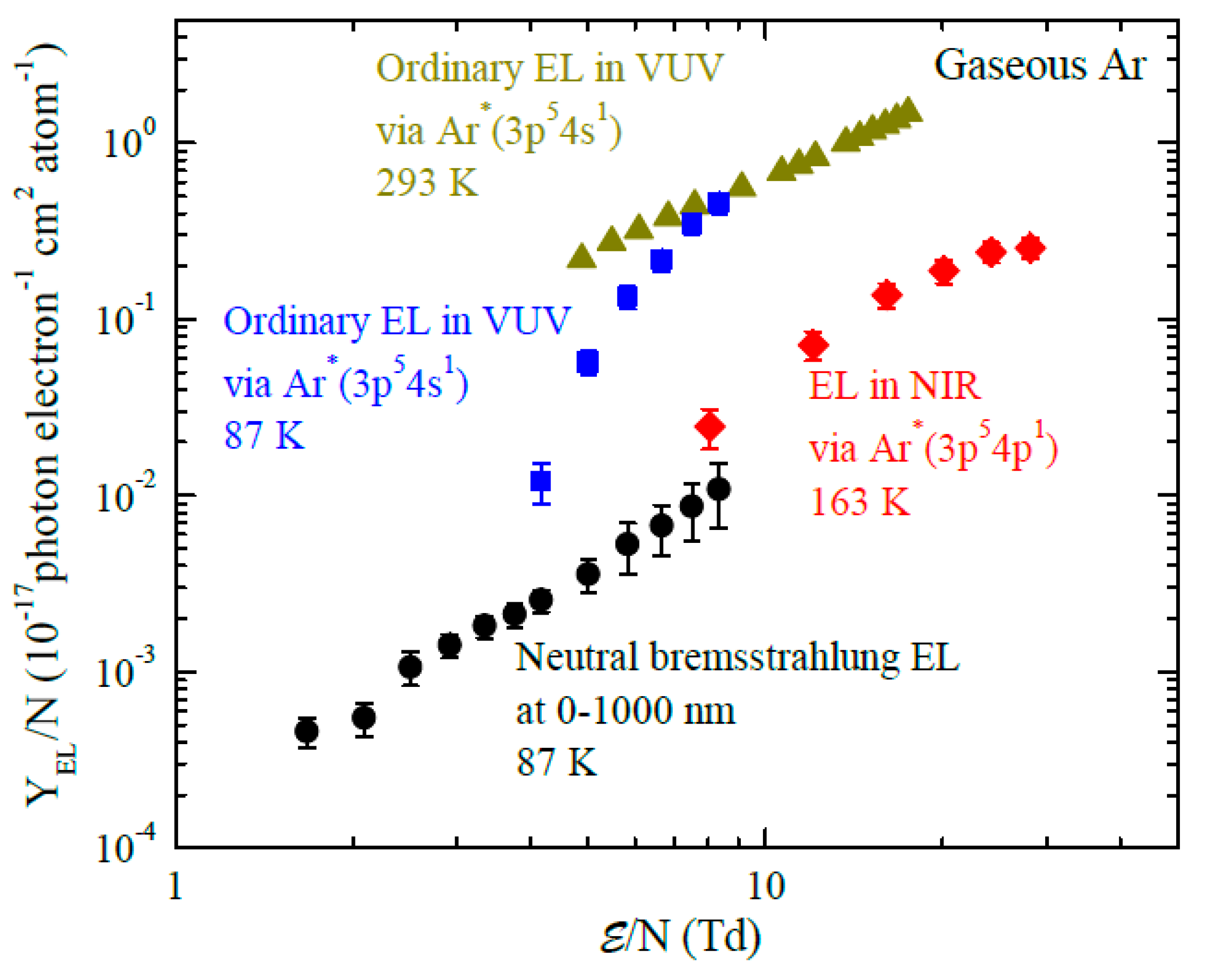
According to modern concepts, there are three EL mechanisms responsible for proportional EL in gaseous Ar and Xe: that of excimer ( A r 2 * or X e 2 * ) emission in the VUV (“ordinary” EL), that of emission due to atomic transitions in the near infrared (NIR), and that of neutral bremsstrahlung (NBrS) emission in the UV, visible and NIR range. The energy level diagrams, appropriate reactions and their constants, relevant to the former two mechanisms, are presented in Figure 3 and Table 1. Photon emission spectra for all three mechanisms and their absolute EL yields are shown in Figure 4 and Figure 5 respectively for Ar [7]. For other noble gases the emission spectra and EL yields look alike [4,5]. For Ar, the EL mechanisms are described below in detail.
Proportional EL is characterized by a reduced EL yield (Y/N), which by definition is the number of photons produced per drifting electron per atomic density and per unit drift path. It is typically plotted as a function of the reduced electric field (E/N), the latter being expressed in Townsends: 1 Td = 10−17 V cm2 atom−1, corresponding to 0.87 kV/cm in gaseous Ar at 1.00 atm and 87.3 K.

3.2. Electroluminescence Due to Excimer Emission

In ordinary (excimer) EL, the electrons accelerated by the electric field excite the atoms, which in turn produce the excimers (excited molecules) in three-body collisions. The excimers are produced in either a singlet A r 2 * (   1 u + ) or a triplet A r 2 * (   3 u + ) state. These states decay with photon emission in the VUV, peaked at 128 nm for Ar and 175 nm for Xe (see Figure 3 and Figure 4 and reactions (1) and (2) in Table 1):
e + A r e + A r *
A r * + 2 A r A r 2 * + A r
A r 2 * 2 A r + h ν
The singlet and triplet excimer states are responsible respectively for the fast and slow emission components observed in proportional EL. Their time constants are of 4.2 ns and 3.1 μs respectively: see Table 1 and references therein. Ordinary EL has a threshold in the electric field, of about 4 Td (see Figure 5), defined by the energy threshold of 11.55 eV of Ar atom excitation in Equation (1).
Ordinary proportional EL has two characteristic properties: a threshold and linear field dependence (far enough from the threshold). For Xe, this can be seen from Figure 6 presenting compilation of the experimental data on EL yield by 2007: the results of the different groups are close, with the exception of early works.
The absolute photon yields of ordinary (excimer) EL were theoretically calculated for Ne, Ar, Kr and Xe in [16] using Monte Carlo simulation in microscopic approach: see Figure 7. One can see from the figure that well above the EL threshold, the theoretical predictions are in rather good agreement with the yields measured in experiment at room temperature, for Ar and Xe. Extrapolating the theoretical EL yield, the EL threshold was determined as 1.5, 4.1, 2.6 and 2.9 Td for Ne, Ar, Kr and Xe respectively [16].
Far enough from the threshold, the EL yield can be parametrized by a linear function, indicating the proportionality of the EL yield to the electric field:
Y / N   [ 10 17 photon   electron 1   cm 2   atom 1 ] = a ·   E / N b  
where reduced electric field E/N is given in Td (10−17 V cm2 atom−1). This equation is universally valid for all temperatures and gas densities. Parameter “b” defines the electric field threshold for proportional EL, while parameter “a” describes the light amplification factor, namely the number of photons emitted by drifting electron per applied voltage across the EL gap. For Ar, Kr and Xe this parameter was measured to be 81 [14], 120 [18] and 140 [17] photon/kV respectively.
The parametrization of the experimental data by linear field dependence was presented in [14] and [17] for Ar and Xe respectively:
Y / N = 0.081 ·   E / N 0.190 ,   for   Ar ;
Y / N = 0.140 ·   E / N 0.474 ,   for   Xe .
However, near the EL threshold this parametrization gives overestimated EL yield values, due to contribution of neutral bremsstrahlung electroluminescence (see Section 3.3). In this case the experimental data relevant to ordinary EL should be used directly. In particular, in two-phase Ar at 87 K and 1.0 atm, the number of photons in the VUV emitted by drifting electron per 1 cm, deduced from experimental data of Figure 5, is 345 and 43 at electric field of 8 and 4.6 Td respectively, the latter corresponding to the nominal operation field of the DarkSide experiment.

3.3. Electroluminescence Due Neutral Bremsstrahlung Effect

In addition to the ordinary EL mechanism, there is a concurrent EL mechanism, based on bremsstrahlung of drifting electrons scattered on neutral atoms, so-called neutral bremsstrahlung (NBrS) [9,13,19]:
e + A r e + A r + h ν
The development of the mechanism is described in detail in [9].
The NBrS differential cross section is proportional to elastic cross section ( σ e l ( E ) ) of electron-atom scattering [9]:
d σ d ν = 8 3 r e c 1 h ν ( E h ν E ) 1 / 2 [ ( E h ν ) · σ e l ( E ) + E · σ e l ( E h ν ) ]
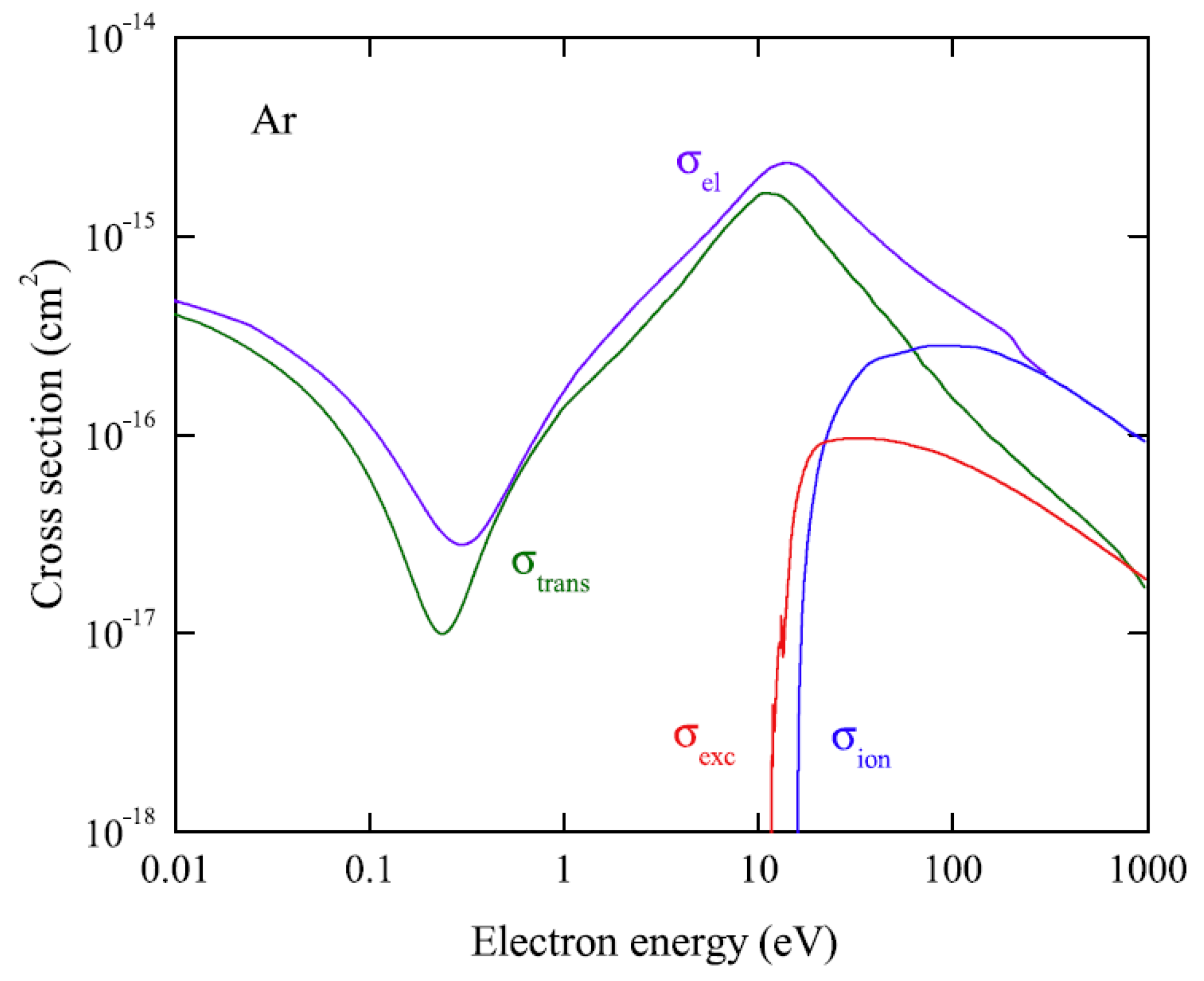
Here r e = e 2 / m e c 2 is the classical electron radius,   c = ν λ is the speed of light, E is the initial electron energy. For electron-atom scattering cross sections in Ar, see Figure 8.
Consequently, the NBrS EL yield is predicted to be maximal for electron energies of the order of 10 eV where the elastic cross section has a maximum, thus corresponding to the electric fields of 4–5 Td. This is confirmed in Figure 9 showing the absolute yield of NBrS EL theoretically calculated in [9], in comparison with that of ordinary EL.
NBrS EL has a continuous emission spectrum, extending from the UV (200 nm) to the visible and NIR range (1000 nm) and even to the radio frequency range [20]: see Figure 4. From Figure 4 and Figure 9 one can see that NBrS EL, albeit being significantly weaker than ordinary EL above the Ar excitation threshold, has no threshold in electric field, in contrast to ordinary EL, and thus dominates below the threshold. Accordingly, the NBrS effect can explain two remarkable properties of proportional EL observed in experiment [9,13,19]: that of the photon emission below the Ar excitation threshold and that of the substantial contribution of the non-VUV spectral component above the threshold.
At lower electric fields, below 4 Td corresponding to Ar excitation threshold, the NBrS theory developed in [9] correctly predicts the absolute value of the EL yield. This is seen when comparing the experimental data on EL yields in Figure 5 to those of the theory in Figure 9 and when comparing the experimental and theoretical photon emission spectra in Figure 10. On the other hand, at higher fields (above 5 Td), the experimental EL yields quickly diverge from those of the theory, exceeding those in the UV spectral range (below 400 nm). In [9] this discrepancy was hypothesized to be explained by the contribution of electron scattering on sub-excitation Feshbach resonance (going via intermediate negative ion state A r ( 3 p 5 4 s 2 )), which might be accompanied by the enhanced photon emission [21].
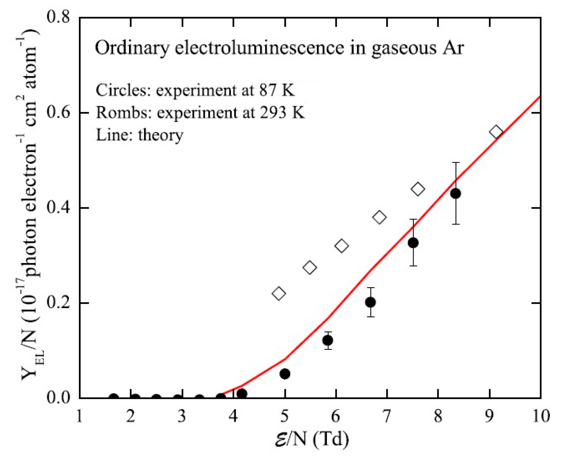
Near the threshold of ordinary EL, namely in the field range of 4–6 Td, it becomes important to take into account the possible contribution of NBrS EL, to correctly measure the EL yield of ordinary EL. Note that just in this field region, namely nominally at 4.6 Td, the DarkSide dark matter search experiment operates [22]. In [9,13] the NBrS contribution was measured, using dedicated spectral devices insensitive to the VUV, and appropriately subtracted from the data obtained with VUV-sensitive devices. The resulted EL yield of ordinary EL, shown in Figure 11, is in good agreement with the theory. On the other hand, the experimental data of [14] in Figure 11 have an excess over those of [9] and theory [16], below 6 Td. It would be logical to explain this discrepancy by considering the NBrS contribution, which was not taken into account in [14].

3.4. Electroluminescence Due to Atomic Transitions in the NIR

At higher electric fields, above 8 Td, another “non-standard” EL mechanism comes into force, namely that of EL in the NIR due to transitions between excited atomic states [4,7,10,11,15,23]. Here the higher atomic levels A r * ( 3 p 5 4 p 1 ) are excited; the transitions between those and the lower excited levels are responsible for the fast emission in the NIR, at 700–850 nm (see Figure 3 and reactions (3) in Table 1):
e + A r e + A r * ( 3 p 5 4 p 1 )
A r * ( 3 p 5 4 p 1 ) A r * ( 3 p 5 4 s 1 ) + h ν
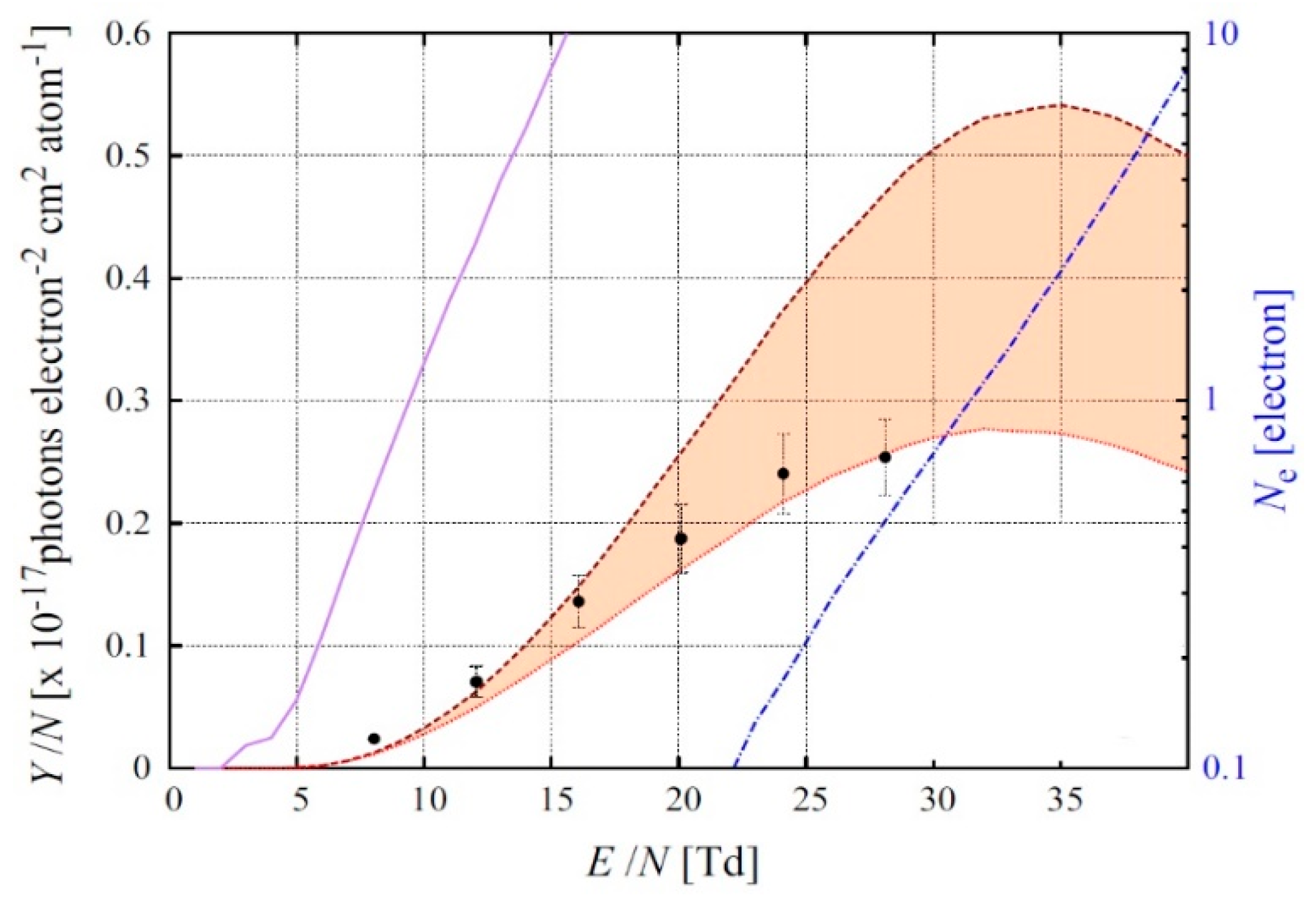
Atomic EL in the NIR has a line emission spectrum: see Figure 4. In addition, it has higher threshold in electric field than ordinary EL (see Figure 12). The absolute yield of atomic EL in the NIR was measured in [15,24]; it was well described by the theory using microscopic approach [23]: see Figure 12. It should be remarked that atomic emission in the NIR is particularly noticeable at even higher fields, above 30 Td, where the avalanche multiplication of the electrons takes place, accompanied by corresponding secondary scintillations: by so-called “avalanche scintillations” [11,25].

3.5. Concepts of Light Signal Amplification

Ordinary EL in Ar and Xe results in two “standard” concepts of light signal amplification in two-phase detectors, depicted in Figure 1. In the first concept used in Ar, the EL gap is optically readout by the SiPM or PMT matrix indirectly, via a wavelength shifter (WLS), typically TPB. This is because the typical cryogenic PMTs and SiPMs are not sensitive to ordinary EL of Ar, at 128 nm.
In the second concept used in Xe, the EL gap is optically read out directly by the PMT matrix, provided that the typical cryogenic PMTs has quartz windows and thus become sensitive to ordinary EL of Xe, at 175 nm.
The concept of direct optical readout (Figure 1 (right)), used for Xe, can also apply to Ar to detect NBrS EL in the non-VUV range. Such an alternative readout concept has the advantage of doing without WLS, in two-phase Ar detectors. This may lead to more stable operation, due to avoiding the problems of WLS degradation and its dissolving in liquid [26] as well as that of WLS peeling off from the substrate. Such a concept was realized in [12]. It might be considered as backup solutions for large-scale two-phase Ar detectors, in case the problem of WLS instability cannot be resolved.

4. Charge Signal Amplification in the Gas Phase of Two-Phase Detector, Using Electron Avalanching

4.1. Charge Signal Amplification Concepts at Cryogenic Temperatures

Over the past two decades, there has been a growing interest in so-called “Cryogenic Avalanche Detectors”: see review [4]. In the wide sense these define a class of noble-gas detectors operated at cryogenic temperatures with electron avalanching (electron multiplication) performed directly in the detection medium, the latter being in a gaseous, liquid or two-phase state, provided by electron impact ionization reaction:
e + A r 2 e + A r +
Earlier attempts to obtain high and stable electron avalanching directly in noble gases and liquids at cryogenic temperatures, using “open-geometry” multipliers, have not been very successful: rather low gains (≤10) were observed in liquid Xe [27,28,29,30] and Ar [31] and low gains (≤100) in gaseous Ar [32] and He [33] at cryogenic temperatures, using wire, needle or micro-strip proportional counters. Moreover, two-phase detectors with wire chamber readout, which initially seemed to solve the problem, turned out to have unstable operation in the avalanche mode due to vapor condensation on wire electrodes [34].
The problem of electron avalanching in cryogenic noble-gas detectors was solved in 2003 [35] after introduction of cryogenic gaseous and two-phase detectors with gas electron multiplier (GEM) readout. GEM [36] and thick GEM (THGEM, [37]) belongs to the class of micro-pattern gas detectors (MPGDs). GEM is a thin insulating film, metal clad on both sides, perforated by a matrix of micro-holes, in which gas amplification occurs under the voltage applied across the film. The typical GEM geometrical parameters are the following: dielectric (Kapton) thickness is 50 μm, hole pitch—140 μm, hole diameter on metal—70 μm. THGEM is a similar, though more robust structure with about ten-fold expanded dimensions. In particular, the typical THGEM geometrical parameters are the following: t/p/d/h = 0.4/0.9/0.5/0.1 mm. Here t/p/d/h denotes “dielectric thickness/hole pitch/hole diameter/hole rim width”.
Contrary to wire chambers and other “open geometry” gaseous multipliers, cascaded GEMs and THGEMs have a unique ability to operate in dense noble gases at high gains [38], including at cryogenic temperatures and in the two-phase mode [39]. Consequently, at present, the basic idea of cryogenic avalanche detectors (CRADs) in the narrow sense is that of the combination of MPGDs with cryogenic noble-gas detectors, operated in a gaseous, liquid or two-phase mode.
The original CRAD concept [35] is the following (see Figure 2): electron avalanching at cryogenic temperatures is performed in pure noble gases using GEM multiplier, either in a gaseous or two-phase mode. In the latter case the conventional two-phase electron-emission detector is provided with charge signal amplification using electron avalanching in the gas phase: the primary ionization electrons produced in the liquid are emitted into the gas phase by an electric field, where they are multiplied in saturated vapor using cascaded GEM multiplier. The proof of principle of this concept was demonstrated in 2003–2006 in two-phase Ar, Kr and Xe [35,40] at appropriate cryogenic temperatures (at around 87 K, 120 K and 165 K, respectively) and in gaseous He and Ne at lower temperatures, down to 2.6 K [41,42].
Later, the original CRAD concept was elaborated: it was suggested to provide CRADs with new features. There are more than a dozen different concepts with charge and light amplification in two-phase and liquid detectors developed by different groups since 2003: their gallery by 2012 is shown in Figure 13. For their detailed description, we refer to review [4] and appropriate references listed in the figure: [15,25,35,40,43,44,45,46,47,48,49,50,51,52,53,54]. The references to such concepts and their realization after 2012 are as follows: [24,55,56,57,58,59,60,61,62].
In Section 4, Section 5 and Section 6, we confine ourselves to the discussion of the most developed and successfully realized concepts, as well as of the physical effects and specific technology underlying them.

4.2. GEM Operation in Pure Noble Gases at Cryogenic Temperatures

In most CRAD concepts, the MPGD multiplier should be able to operate at high gains in dense pure noble gases, particularly in saturated vapor and at cryogenic temperatures. Fortunately, unlike open-geometry gaseous multipliers (e.g., wire chambers), cascaded GEMs and THGEMs permit attaining high (≥103) charge gains in “pure” noble gases at atmospheric pressure, presumably due to considerably reduced photon-feedback effects. At room temperature, this remarkable property was discovered first for Ar [38,63] and then for other noble gases [4,39,64,65], using GEM multipliers. For operation of other MPGD multipliers in “pure” noble gases at room temperature, we refer to review [4].
It should be remarked that the stable operation of GEMs at cryogenic temperatures is a non-trivial fact, since the electrical resistance of their dielectric materials considerably increases with the temperature decrease, i.e., by an order of magnitude per 35 degrees for Kapton GEMs [66], which might result in strong charging-up effects within the holes. Fortunately, the latter did not happen: the charging-up effects for GEMs have not been observed. The GEM performance in gases at cryogenic temperatures was found to be generally independent of temperature down to ~100 K, at a given gas density [66]: stable and high-gain GEM operation was observed in all noble gases and in their mixtures with selected molecular additives that do not freeze in a wide temperature range (CH4, N2 and H2). This is seen from Figure 14 (left): rather high triple-GEM gains were reached at cryogenic temperatures, exceeding 104 in Ar, Kr and Xe+CH4.
It is amazing that GEMs were able to operate in electron avalanching mode at even lower temperatures, down to 2.6 K in gaseous He [41,42]. On the other hand, high GEM gains observed in He and Ne above 77 K were reported to be due to the Penning effect in uncontrolled (≥10−5) impurities (i.e., N2) which froze out at lower temperatures, resulting in the considerable gain drop at temperatures below 40 K: see Figure 14 (right). A solution to the gain-drop problem at lower temperatures was found in [41]: Ne and He can form high-gain Penning mixtures with H2 at temperatures down to ~10 K. This is seen from Figure 14 (left): triple-GEM gains exceeding 104 were obtained at 57 K in the Penning mixture Ne+0.1%H2, its density corresponding to that of saturated Ne vapor in the two-phase mode. Unfortunately, this does not work for two-phase He, due to the very low H2 vapor pressure at 4.2 K.

4.3. Two-Phase Detectors with GEM Multipliers

Regarding GEM operation in two-phase detectors, most promising results were obtained for two-phase Ar detectors (see Figure 15): the charge gain of 5000 with triple-GEM readout was routinely attained [40] and the stable operation for tens of hours at this gain was demonstrated [67]. This maximum gain value should be compared to that of 600 and 200 obtained in GEM-based two-phase Kr and Xe detectors respectively: see Figure 15.
In this review the charge gain is defined as the ratio of the output anode charge of the GEM or THGEM multiplier incorporated into the two-phase detector to the input “primary” charge, i.e., to that of prior to multiplication measured in special calibration runs.
The successful performance of two-phase Ar detectors with triple-GEM charge readout is illustrated in Figure 16 and Figure 17. In particular, the high triple-GEM gain provided the operation of the two-phase detector in single-electron counting mode (Figure 16) [68]. It should be remarked that though the single-electron spectra are well separated from electronic noise at gains exceeding 5000, they are described by an exponential function (rather than by a peaked function). The latter is generally a rule for gaseous multipliers operated in proportional mode, due to intrinsically considerable fluctuations of the avalanche size. Consequently, the single- and double-electron events can hardly be distinguished in two-phase Ar detectors with GEM (or THGEM) charge readout. For that, the combination with PMT- or SiPM-based optical readout should be used, as suggested in [15,24]. Accordingly, the function of GEM- or THGEM-based charge readout would be to provide superior spatial resolution.
Figure 17 demonstrates the unique ability of the two-phase Ar detector with GEM charge readout to observe directly and simultaneously the fast and slow components of electron emission through the liquid-gas interface [69]. The fast component is due to the hot electrons, heated by an electric field, while the slow component is due to the electrons reflected from the potential barrier and then thermalized [4]. Note that the two-phase Ar detector with optical readout of the EL gap cannot provide such an ability, due interference with the slow component of excimer (VUV) emission. It should be also emphasized that the slow component has never been observed in two-phase Kr and Xe systems, presumably due to higher potential barrier at the interface as compared to Ar. Vice versa, the fast component has never been observed in two-phase He and Ne systems since the electrons in liquid He and Ne are localized in the bubbles and thus cannot be heated by the electric field. Consequently, the two-phase Ar system is unique in this sense.
It should be remarked that all the gain data of this section were obtained with GEMs with relatively small active area, of 2.8 × 2.8 cm2. Unfortunately, as we will see later, the maximum gain decreases with the multiplier active area.

4.4. Two-Phase Detectors with THGEM Multipliers

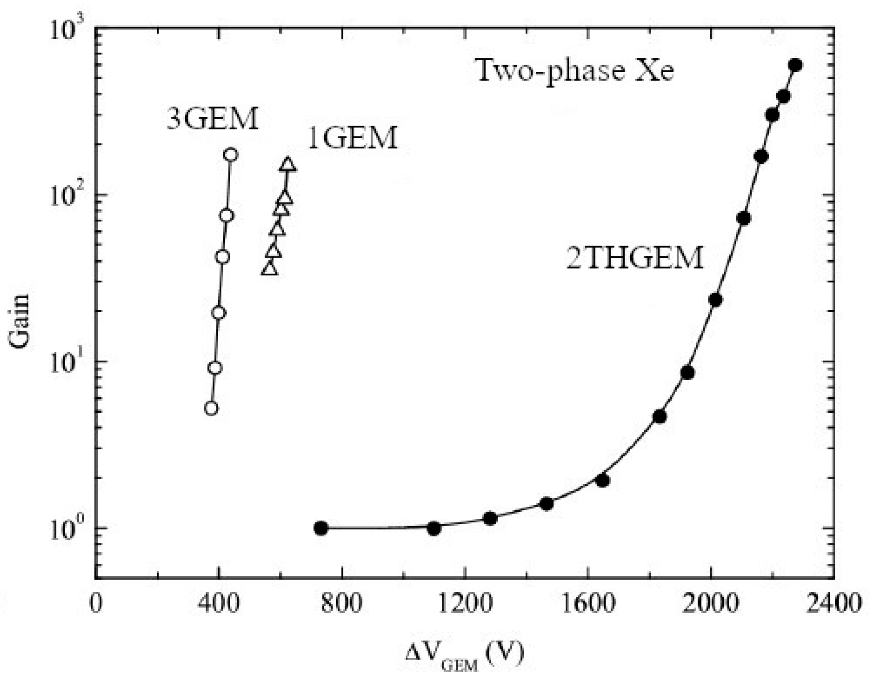
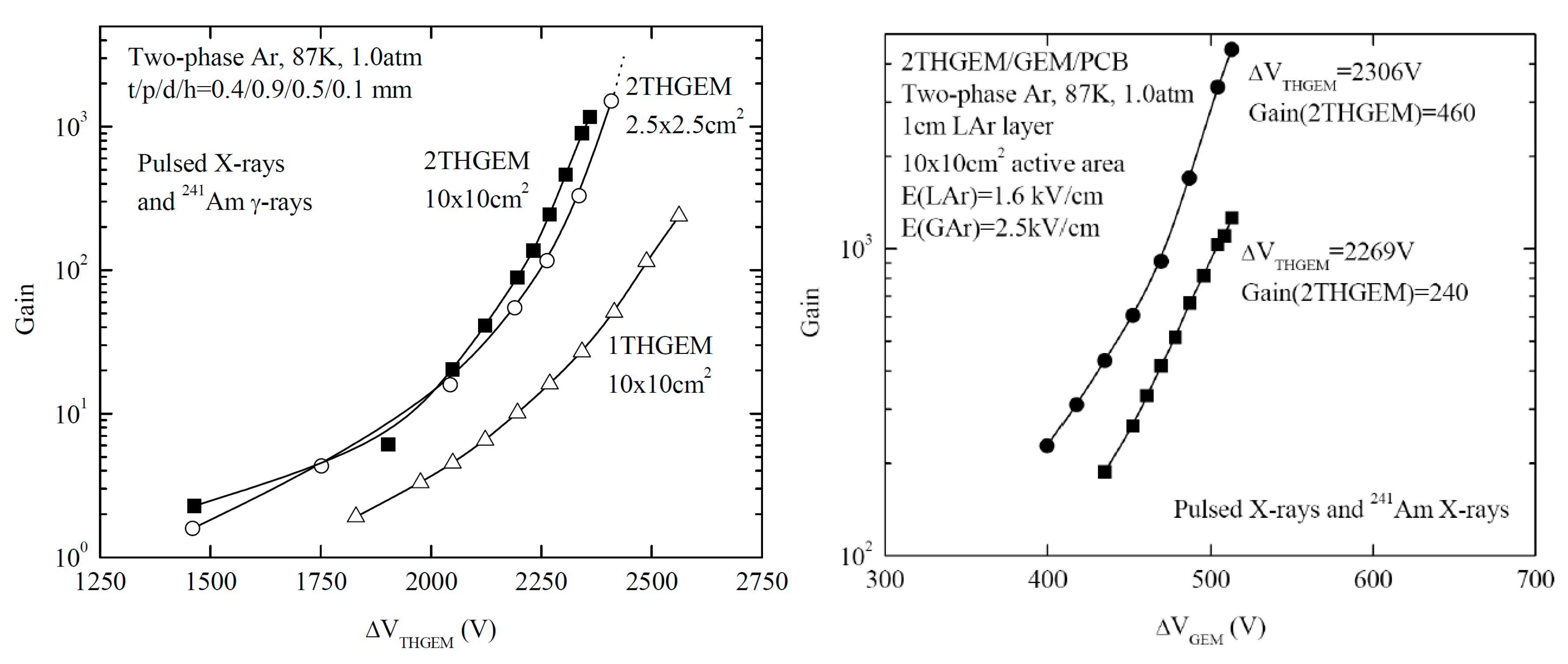
In two-phase detectors with THGEM charge readout, the maximum gains are comparable to those with GEM readout: see Figure 18 and Figure 19 (left). Gains as high as 3000 [48] and 600 [70] were obtained in two-phase detectors in Ar and Xe respectively, with double-THGEM multipliers having active area of 2.5 × 2.5 cm2.
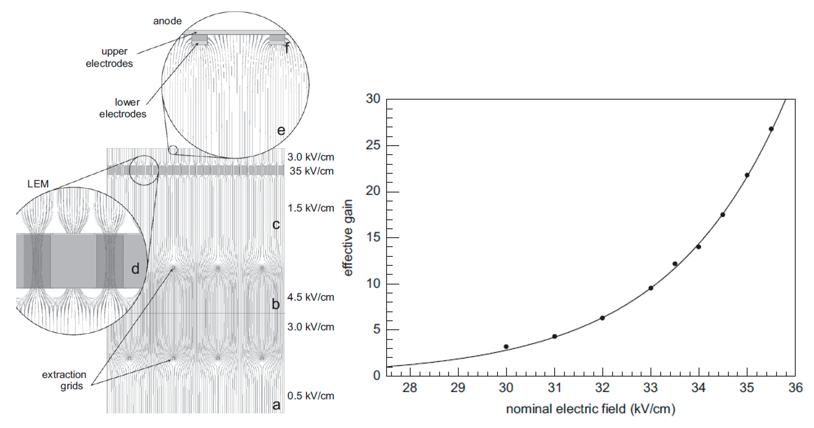
However for larger active area, of 10 × 10 cm2, the maximum gain in two-phase Ar detector decreased three-fold: down to about 1000 for double-THGEM multiplier [70] and 100–200 for single-THGEM multiplier [72,73]: see Figure 19 (left) and Figure 20 (right). This could result from the larger number of holes, implying a larger discharge probability on defects. Note that the nominal electric field in Figure 20, defined as the THGEM voltage divided by its dielectric thickness, is higher than the real electric field in the THGEM hole.
The maximum gains of 100–1000 are obviously not sufficient for charge readout in a single-electron counting mode. Nevertheless, the gain of about 80, obtained in two-phase Ar detector with single-THGEM having 2D readout [73], permitted to obtain track images, demonstrating the excellent imaging capability of two-phase Ar detectors with THGEM multiplier charge readout even at such a moderate gain. This technique is of particular importance for giant liquid Ar detectors for long-baseline neutrino experiments. At present, the R&D of this technique has continued as part of the ArDM and DUNE experiments [74,75,76]. It should be remarked that in that community another terminology is used, namely “dual-phase TPC” and “Large Electron Multiplier” (LEM).
The further reduction of the maximum charge gain in two-phase Ar detector when increasing the active area up to 40 × 40 and 50 × 50 cm2, was reported in [74] and [76] respectively. For the latter, the THGEM multiplier could not operate at nominal electric fields higher than 28 kV/cm, i.e., at charge gain higher than 3 according to Figure 20 (right). This is the real problem; it is discussed below.
An interesting way to increase the maximum charge gain in two-phase Ar CRADs was suggested in [72], namely that using a hybrid 3-stage 2THGEM/GEM multiplier: see Figure 19 (right). The idea was that the avalanche charge from a THGEM hole would be shared between several GEM holes. This might reduce the overall avalanche charge density, believed to be responsible for the discharge development, and thus might increase the discharge voltage. The maximum gain as high as 5000 was attained for 10 × 10 cm2 active area, in practical configuration when the last multiplier stage was followed by a printed circuit board (PCB) anode, convenient for readout electronics coupling. This is almost enough for stable operation in single-electron counting mode with 2D readout, for which charge gains of 104 are needed. It should be noted that the idea of hybrid multiplier, combining hole multipliers with different hole densities, can be realized without “fragile” GEMs: by cascading more robust THGEMs of different geometry, with sequential increasing hole densities and decreasing thicknesses.

4.5. Gain Limit, Gain Stability and Discharge-Resistance Problems in Two-Phase Detectors with GEM and THGEM Multipliers

Several problems of the performance of two-phase Ar detectors with GEM and THGEM charge readout remain unsolved. The first problem is that of the gain limit due to discharges. The obvious way to increase the gain would be adding an additional multiplication stage, i.e., up to overall 4 stages in the case of GEMs and 3 stages in the case of THGEMs. Additionally, it looks attractive to combine GEMs and THGEMs in a hybrid multiplier such as that discussed above. Another way is an optical readout from THGEMs. Indeed, the THGEM charge gain of the order of 100 is still significant if combined with optical readout using SiPM matrices [55] or CCD cameras [60], and might be sufficient for track imaging and even for single-electron counting mode. These will be discussed in the following section.
The second problem is that of the resistance to electrical discharges of “standard” (thin Kapton) GEMs. It was observed [77] that when operating two-phase Ar detectors with triple-GEM multiplier at maximum gains (approaching 104), the triple-GEM was not able to withstand electrical discharges on a long term: after several series of measurements, the maximum reachable gain decreased by several times. Obviously, this is due the low resistance of thin GEMs to discharges because of metal and/or carbon evaporation and their deposition on the insulator in the GEM holes. The solution of the problem might be switching to thicker THGEMs that were found to behave in more reliable way under discharges, or else combining THGEM and GEM multipliers or THGEM multipliers with increasing hole density, as discussed above.
There is another unsolved problem in two-phase CRAD performances. Namely, the performance of MPGD multipliers in two-phase Ar and Xe is not fully understood: not all multiplier types were able to operate with electron multiplication in saturated vapor. In two-phase Ar, while G10-based THGEM multipliers successfully operated for tens of hours with gains reaching a few thousands, others, namely RETHGEM and Kapton THGEMs, did not show stable multiplication in the two-phase mode [4,72]: they either did not multiply at all (with gain below 1) or showed unstable operation due to large gain variations. In addition, in [78] it was reported on the unsuccessful performance of the Micromegas multiplier in two-phase Xe: in half an hour the multiplication collapsed. The most rational explanation of these instabilities is the effect of vapor condensation within the THGEM holes or Micromegas mesh that prevents electron multiplication. The criteria for such a condensation are not yet clear. It could be that the specific properties of the holes and electrodes might play a role, i.e., the wetting capability depending on the electric-field non-uniformity and consequently on the MPGD geometry, as well as on the temperature gradients, the latter in turn depending on the electrode’s heat conductivity.

4.6. THGEM as Interface Grid in Two-Phase Detectors

In addition to the performance as charge multiplier, THGEM can be used as an interface grid immersed in the liquid (see Figure 1), acting as an effective electron transmission electrode defining the electron emission and EL regions of the two-phase detector [79]. Examples of such THGEM electrodes used in practice [9,12] are shown in Figure 21, left. The feature of such a THGEM interface grid is that one must apply a high enough voltage across it to have the 100% electron transmittance. In particular, in liquid Ar, for the THGEM electrode with 28% optical transparency the nominal electric field should exceed 5 kV/cm to provide the 100% electron transmission [79]: see Figure 21, right. On the other hand, it was shown there that the THGEM with 75% optical transparency provides 100% electron transmission at already 2 kV/cm of nominal electric field. The advantage of such THGEM electrodes compared to wire electrodes is that they are quite rigid which avoids the problem of wire grid sagging under high electric field in large-area two-phase detectors.

5. Combined Charge/Light Signal Amplification in the Gas Phase of Two-Phase Detector, Using Avalanche Scintillations

5.1. Two-Phase Ar Detector with Combined THGEM/SiPM-Matrix Multiplier

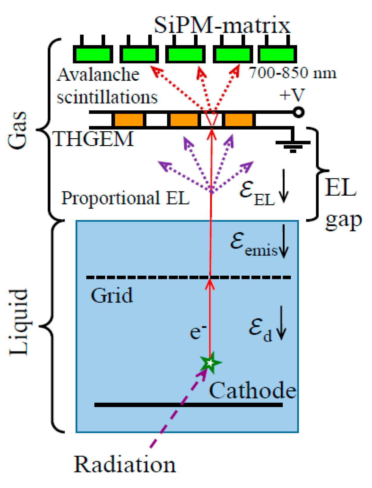
Figure 22 shows the concept of combined charge/light signal amplification in two-phase detector with EL gap, using avalanche scintillations. In this concept, the combined THGEM/SiPM-matrix multiplier is coupled to the EL gap: the THGEM provides the charge signal amplification by operating in electron avalanching mode, while the SiPM matrix optically records avalanche scintillations produced in the THGEM holes thus providing the light signal amplification with position resolution. Since ordinary SiPMs produced by industry are typically sensitive to the NIR but not sensitive to the VUV, the avalanche scintillations can be recorded in two ways: either directly, using avalanche scintillations due to atomic transitions in the NIR (see Figure 4 and Figure 5), or indirectly via WLS film in front of the SiPM matrix, using excimer avalanche scintillations in the VUV. The earlier works on realizing this concept in two-phase Ar [55] and Xe [56] detectors should be mentioned, albeit with smaller active area and SiPM matrix size.
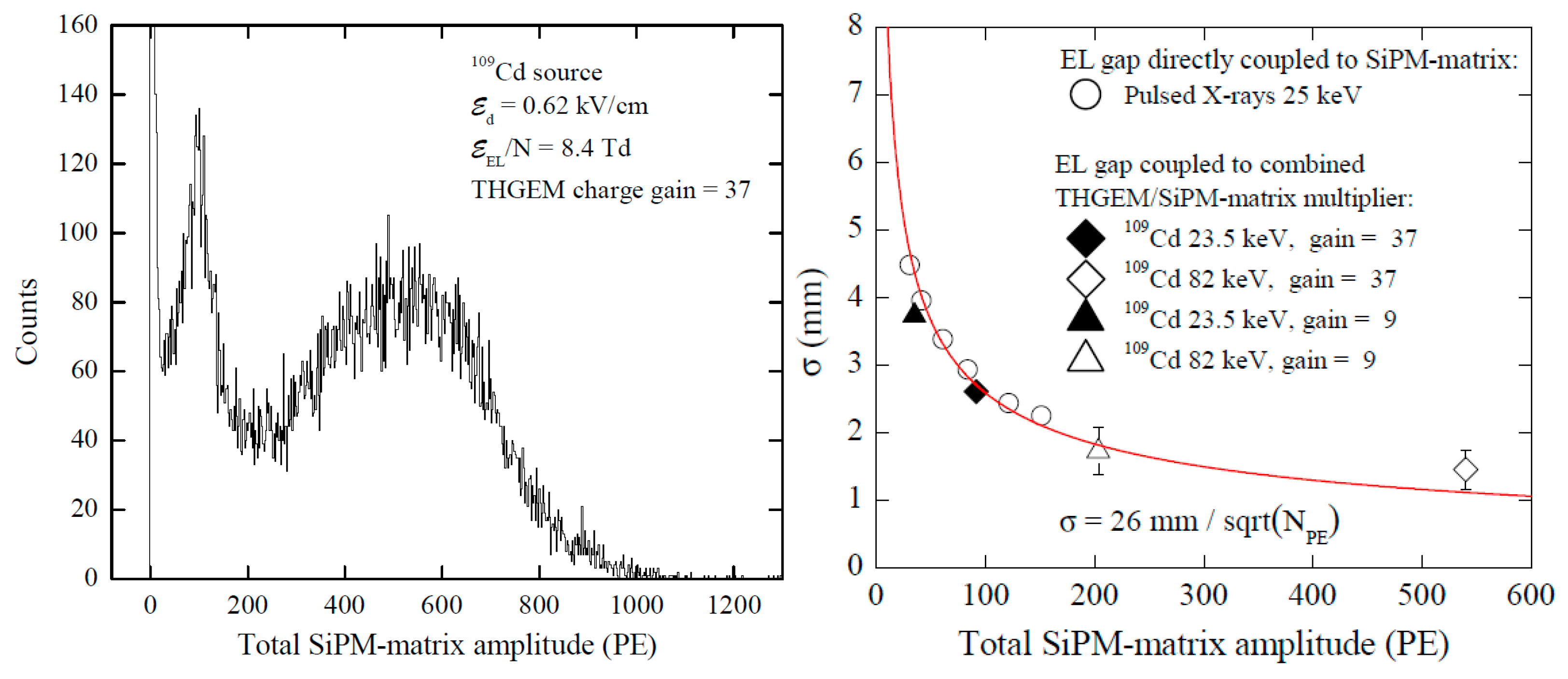
In the most elaborated way, the concept was realized in two-phase Ar detector with combined THGEM/SiPM-matrix multiplier of 10 × 10 cm2 active area in [12], using a 5 × 5 SiPM matrix having 1 cm pitch of SiPM elements. The amplitude and position resolution properties of the detector are illustrated in Figure 23. As large as about 500 photoelectrons were recorded by the SiPM matrix for 88 kev gamma-rays from 109Cd source, at rather moderate THGEM charge gain, of 37. This would correspond to the detector yield of about 1–2 photoelectrons per drifting electron in the gas phase [12]. Moreover, the highest position resolution was obtained in this detector than ever was measured for two-phase detectors with EL gap: σ = 26   mm / N P E , where NPE is the total number of photoelectrons recorded by the SiPM matrix. Such photoelectron yield and positions resolution would be sufficient for applications in neutrino and dark matter search experiments.

5.2. Two-Phase Ar Detector with Combined THGEM/CCD-Camera Multiplier

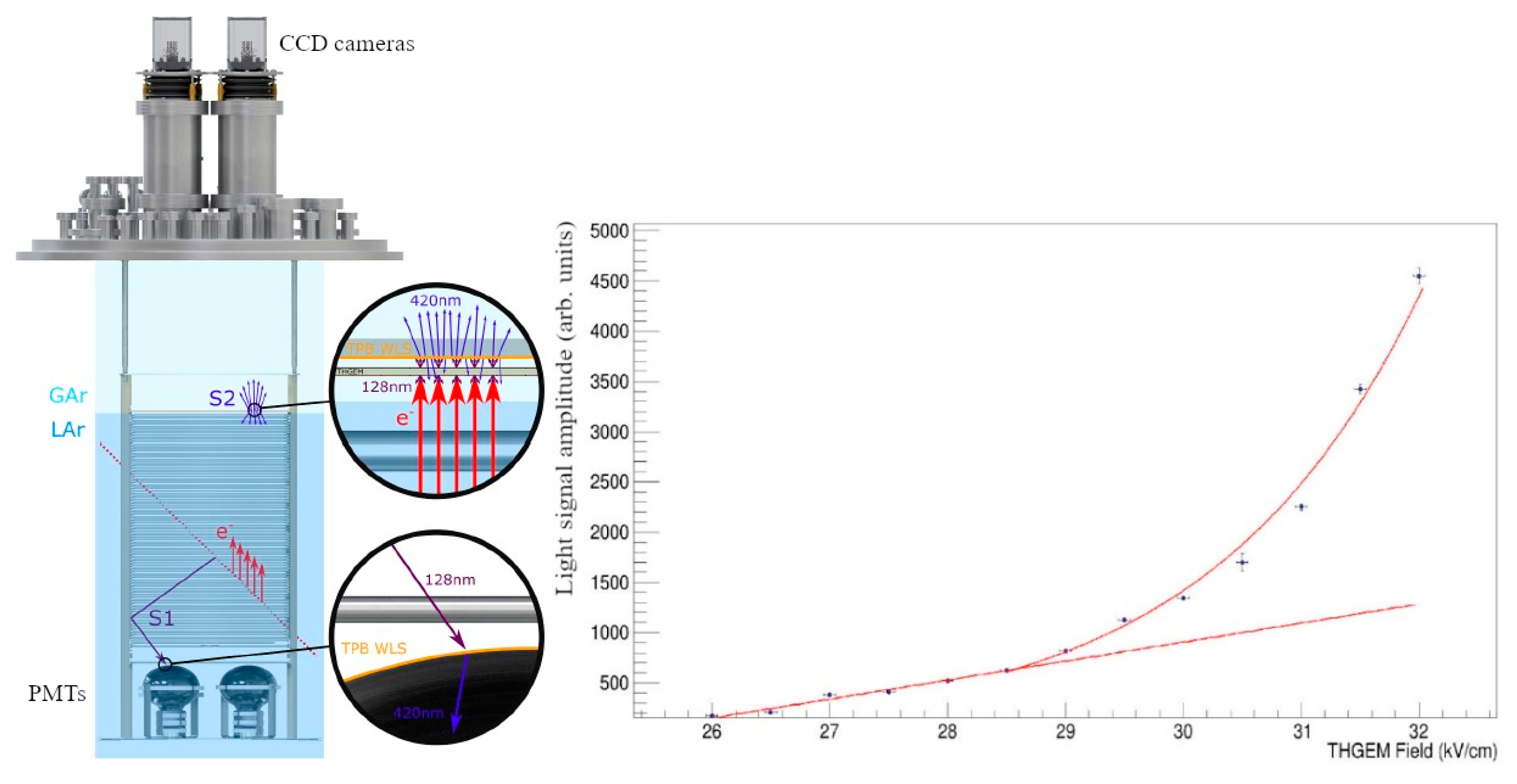
Figure 24 (left) shows the concept of combined charge/light signal amplification in a two-phase Ar detector, using avalanche scintillations in a combined THGEM/CCD-camera multiplier [60]. It is similar to that considered above, with the difference that the SiPM matrix is replaced by the CCD cameras. Here the avalanche scintillations were recorded indirectly via WLS film behind the THGEM plate, using excimer avalanche scintillations in the VUV. In the most elaborated way, the concept was realized in [61] in two-phase Ar detector with 54 × 54 cm2 active area and overall liquid Ar mass of 1 t. The advanced CCD cameras, with additional electronic amplification of the signal (an electron multiplying charge coupled device (EMCCD)) were used, which allowed for single photoelectron counting.
Using such detector, 3D reconstruction of cosmic muon tracks and beamline interactions has been successfully performed. The detector was proposed to be employed in future large scale two-phase liquid Ar neutrino experiments as an alternative readout method, replacing the highly segmented anode planes.
One can see from Figure 24 (right), showing the light signal amplitude dependence on the THGEM electric field, that two operation modes were observed: that of proportional EL (linear part) and that of electron avalanching (exponential rise part). The optical readout allows to measure the THGEM charge gain ad hoc: using the dependence of the light signal intensity on the electric field. In particular, at the maximum field of 32 kV/cm, the avalanche light gain, defined as the measured light intensity normalized to that of the linear extrapolation from the lower electric fields, is close to 4. This avalanche light gain corresponds to larger charge gain, because secondary (avalanche) electrons produce less EL light per drifting electron compared to initial electron, since they drift over smaller distance in the hole. If to approximate the THGEM hole by a parallel-plate gap, it can be shown that the light gain of 4 corresponds to the charge gain of 8.

6. Charge and Light Signal Amplification in the Liquid Phase

In the liquid, the excited, ground and ionized atomic states transform to the exciton, valence and conduction bands, respectively (see Figure 3 and [7]), in particular in Ar, to the A r * ( n = 1 , P 2 3 / 2 ) and A r * ( n = 1 , P 2 1 / 2 ) excitons, which reflect the P 3 1 and P 1 1 levels of the A r * ( 3 p 5 4 s 1 ) atomic states. According to reaction (15) of Table 1, the excitons are immediately trapped in singlet or triplet excimer states A r 2 * (   1 , 3 u + ) . The singlet   1 u + and triplet   3 u + excimers provide the fast and slow emission components in the VUV for scintillations in liquid Ar (reaction (16) of Table 1)) with a lifetime of 7 ns and 1.6 μs respectively (see [7] and references therein). This mechanism is the basic one for scintillations in liquid Ar and is similar to that of ordinary electroluminescence in gaseous Ar described in Section 3.2. As for the other scintillation mechanism considered in that section, namely that of atomic transitions in the NIR in gaseous Ar, it does not work in liquid Ar due to the disappearance of analogues of the higher excited levels. On the other hand, there are some indications that the neutral bremsstrahlung emission may still exist in liquid Ar: see Section 6.1 and Section 6.2.

6.1. Charge and Light Signal Amplification in Liquid Xe and Liquid Ar Using wires, Strips and Needles

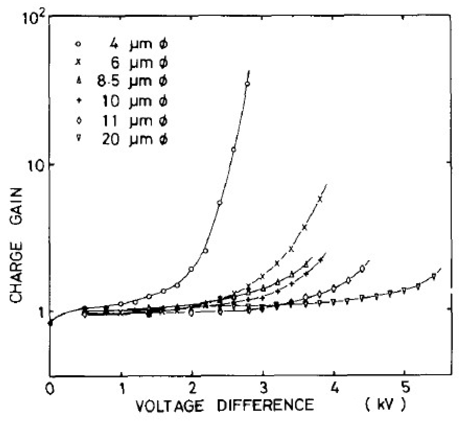
The attempts to obtain high and stable charge amplification directly in noble-gas liquids, using “open-geometry” multipliers, have not been very successful: rather low charge gains (≤10) were observed in liquid Xe using wire proportional counters [27,28,30] and micro-strip counter [29] and in liquid Ar using needle counter [31]. This is clear from Figure 25 showing charge gain in liquid Xe for different wire diameters as a function of the applied voltage.
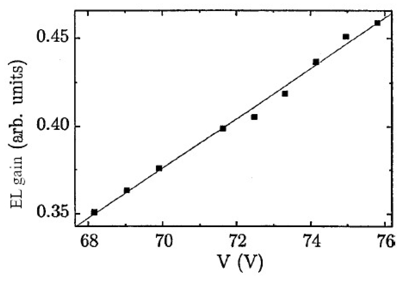
On the other hand, proportional electroluminescence (EL) observed in liquid Xe using thin wires and VUV-sensitive PMTs [28,30] looks more promising for applications [62]: see Figure 26. In particular, the maximum proportional EL yield of about 300 photons per drifting electron was obtained using 10 μm diameter wire [30]. In a wide voltage range, proportional EL gain was well described by a linear function, defining a nominal EL threshold at a certain electric field. In particular, the nominal thresholds for proportional EL and electron multiplication were measured as about 400 and 700 kV/cm, respectively. The linear dependence of proportional EL gain on the electric field and the existence of the threshold for EL in liquid Xe were confirmed also in a needle-type device [80]: see Figure 27.
It is interesting however, that below the nominal EL threshold the EL signal was still observed in [30]: see Figure 26 (left). Moreover, the pulse width for such “alternative” EL dramatically dropped down compared to “ordinary” EL (see Figure 26 (right)), indicating that alternative EL is fast. This under-threshold and fast EL in liquid Xe looks very similar to under-threshold and fast EL in gaseous Ar described in Section 4.2, where it was convincingly explained by the neutral bremsstrahlung (NBrS) effect: compare Figure 26 (left) to Figure 5 and Figure 9. This similarity has lead us to a conclusion that proportional EL in liquid Xe, observed under the nominal EL threshold, of about of 400 kV/cm, with high probability is due to the NBrS effect as well. Note that the similar hypothesis has been proposed in [9] to explain proportional EL in liquid Ar, observed in immersed THGEMs and GEMs at relatively low fields: see below.

6.2. Light Signal Amplification in Liquid Ar Using THGEMs and GEMs

In liquid Ar, proportional EL, with its characteristic properties of having a threshold and linear field dependence, was observed in immersed THGEM and GEM structures in [4,49]: see Figure 28. The mystery of the results obtained is that liquid Ar EL started at much lower electric fields compared to liquid Xe, at about 60 kV/cm, which almost an order of magnitude lower than that of liquid Xe. In addition, these electric fields are far less than those of 3 × 10³ kV/cm expected from theoretical calculations for EL in liquid Ar due to atomic excitation mechanisms [81].
It was supposed in [9] that the NBrS effect could be responsible for proportional EL in liquid Ar observed in immersed GEM-like structures. Indeed, the electric fields in the center of GEM or THGEM holes used in liquid Ar, of 60–140 kV/cm, correspond to E/N = 0.3–0.7 Td that are not that small. For such reduced electric fields, the theory predicts that NBrS EL already exists: see Figure 9. It also predicts the linear dependence of the EL yield observed in experiment. Thus, one cannot exclude the NBrS origin of proportional EL in noble-gas liquids at lower electric fields.
Another possible explanation might the presence (for some reason) of gaseous bubbles associated to the THGEM and GEM holes, within which proportional EL in the gas phase could develop. This effect will be discussed below. This hypothesis, of bubble-assisted EL, could be confidently tested by measuring the EL emission spectrum in the NIR: it would be confirmed if the emission spectrum would consist of atomic lines corresponding to gaseous Ar. Otherwise, the continuous spectrum would indicate on the real liquid Ar emission. This method has been realized in [82] when studying electrical breakdown in liquid Ar; the results will be discussed in the following.

6.3. Liquid-Hole Multipliers in Liquid Ar and Liquid Xe

The liquid-hole multiplier (LHM) concept [57,58] has emerged after observation of proportional EL in THGEMs immersed in liquid Xe: see Figure 29 [83]. Notice the linear voltage dependence of EL yield and rather low voltage threshold for EL, corresponding to the electric field in THGEM holes of about 10 kV/cm. This field value is one and two orders of magnitude smaller than that for proportional EL in liquid Ar using THGEMs and in liquid Xe using wires, respectively. Therefore, such a low threshold EL can hardly be explained by ordinary EL or NBrS EL. This effect was proved to be due to proportional EL in the bubbles formed in the holes of the THGEM and under it [58,84].
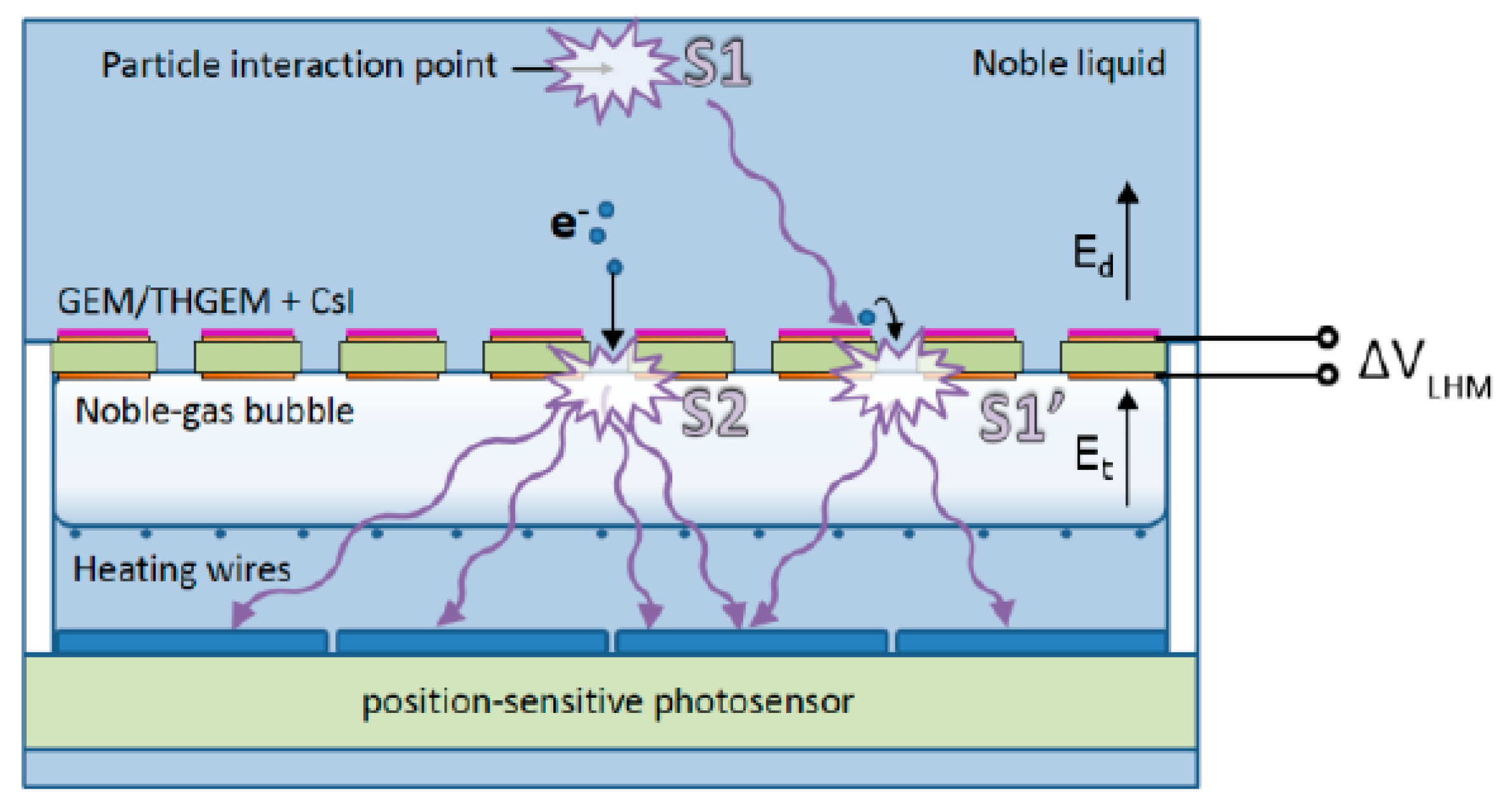
In the LHM concept, shown in Figure 30, the noble-gas bubble is formed in noble-gas liquid under the THGEM or GEM plate in a controlled way using heating wires. Radiation-induced ionization electrons and scintillation (S1)-induced photoelectrons from a CsI photocathode (optionally deposited on top of the THGEM) are focused into the THGHEM holes; both cross the liquid-vapor interface and create EL signals (S2 and S1′, respectively) in the bubble.
In some sense, the LHM bubble resembles the DarkSide scheme [85], where a gas pocket is formed using heating wires, confined from above by a metallized quartz-plate anode. However, there is a fundamental difference: the gas bubbles in LHM are kept from coming up through the THGEM holes due to surface tension. This allows ionization to enter the gas phase from both sides of the liquid: from below and above the bubble.
Figure 31 illustrates the LHM performance in liquid Xe and liquid Ar: the EL (S2) signals are distinctly seen along with the primary scintillation (S1) signals. In liquid Xe, the EL yield of as high as 400 photons per drifting electron was reached, which is comparable with that obtained in traditional two-phase Xe detector with 1 cm thick EL gap. Nevertheless, further research is needed before this technique can be applied in real rare-event experiments.

6.4. Breakdowns in Noble-Gas Liquids

Breakdowns in noble-gas liquids are relevant to the subject of this review because they are accompanied by both charge multiplication and electroluminescence. Their study is important for practical implementation of large liquid Ar TPCs for neutrino experiments, where the high electrical potentials are envisioned, from 100 kV to 1 MV.
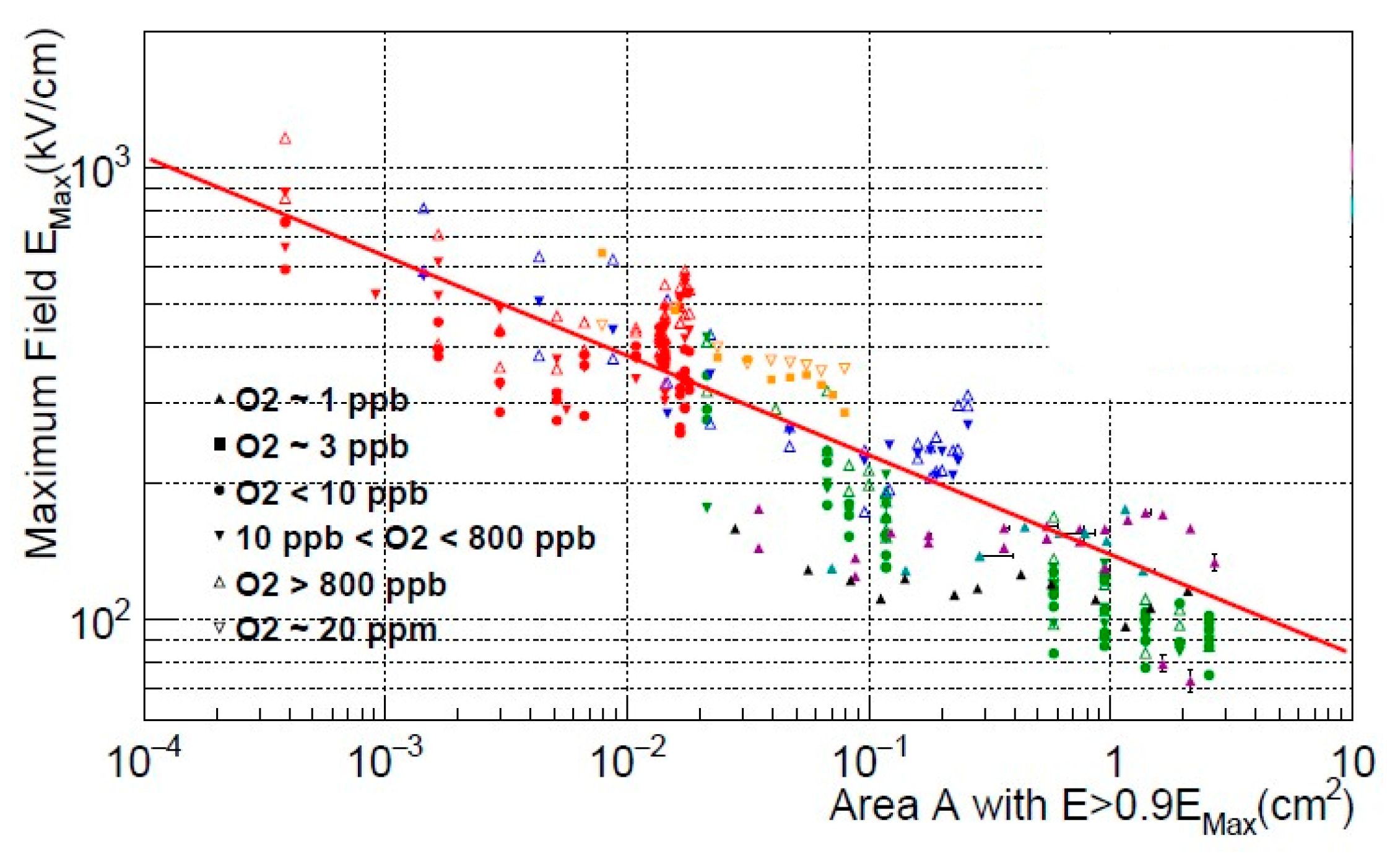
The breakdown mechanism is not fully understood; it includes several physical effects such as electron field emission, streamer propagation and electroluminescence. Nevertheless, the universal empirical rule was revealed in breakdown measurements at cm scale [82,86,87,88]: the threshold for dielectric breakdown in any noble-gas liquid decreases with the increase of the surface area of the electrodes according to inverse power law:
E m a x = C · A p  
where C is a material-dependent constant, A is the stressed area (defined as the area with an electric field intensity above 90% of its maximum), and p 0.25 . See also Figure 32 showing the breakdown field in liquid Ar as a function of stressed area. There does not appear to be a significant difference between breakdown behavior in liquid Ar and liquid Xe [88].
It is remarkable that the breakdown in liquid Ar was proposed to have a two-phase nature [82]: while at its first stage electron electroluminescence and avalanching occurred directly in the liquid (induced by field emission of the electrons from the cathode), at the second stage the streamer propagated in the elongated gas bubble. This hypothesis is supported by Figure 33. It shows photon emission spectra in the visible range for a breakdown in liquid Ar at the first (field emission) and the second (streamer) stage. The field emission stage was observed in the form of a glowing cone. These spectra feature the presence of both a liquid and a gas phase in the breakdown. Indeed, the curve with a broad continuum resembles the scintillation continuous spectrum observed in the visible range in liquid Ar [89], while the curve featuring distinct peaks around 700 and 750 nm is attributed to the line spectrum in the NIR due to A r * ( 3 p 5 4 p 1 ) A r * ( 3 p 5 4 s 1 ) transitions in gaseous Ar (see Figure 4 and Equation (9)).

7. Conclusions

In this work we have reviewed physics and techniques of direct signal amplification in the detection media of two-phase argon and xenon detectors. Originally given rise from the idea of the two-phase detector itself, the concept of amplifying the primary ionization signal (S2 signal) had triggered intense and difficult R&D work over the last 20 years. This resulted in a large variety of advanced concepts of S2 signal amplification developed in this period. All these concepts are based on two physical effects: electroluminescence and electron avalanching under high electric fields, both in the gas and in the liquid phase.
For the time being the most intensively used concept (particularly in dark matter search experiments) is that of the “light signal amplification” utilizing proportional electroluminescence in the gas phase. Another most intensively studied concept is that of the “charge signal amplification” using electron avalanching in THGEM multipliers. This however encounters difficulties with large active areas needed for large-scale liquid Ar detectors. The solution of the problem might be to use combined charge/light signal amplification.
In addition, this R&D work has significantly advanced understanding of the physical effects related to amplification processes in two-phase detectors. Among them are new electroluminescence mechanisms, including that due to neutral bremsstrahlung effect.
Finally, these kinds of techniques may come to be in great demand in rare-event experiments, such as dark matter searches, coherent neutrino-nucleus scattering and giant liquid Ar detectors for neutrino physics. Further studies in this field are in progress.

Funding

The minor part of the work (Section 4), was supported by Russian Foundation for Basic Research (project No. 18-02-00117). The major part of the work (Section 1, Section 2, Section 3, Section 5, Section 6 and Section 7) was supported by Russian Science Foundation (project No. 20-12-00008).

Acknowledgments

This review was triggered by author’s participation in preparing a forthcoming book “Two-phase emission detectors”, in collaboration with D. Akimov, A. Bolozdynya and V. Chepel, to be published by World Scientific Publishing Co. Pte. Ltd.

Conflicts of Interest

The author declares no conflict of interest

References

  1. Dolgoshein, B.A.; Lebedenko, V.N.; Rodionov, B.U. New method of registration of ionizing-particle tracks in condensed matter. JETP Lett. 1970, 11, 351. [Google Scholar]
  2. Aprile, E.; Bolotnikov, A.E.; Bolozdynya, A.; Doke, T. Noble Gas Detectors; Wiley-VCH: Weinheim, Germany, 2006. [Google Scholar]
  3. Bolozdynya, A. Emission Detectors; World Scientific Publishing: Singapore, 2010. [Google Scholar]
  4. Buzulutskov, A. Advances in cryogenic avalanche detectors. J. Instrum. 2012, 7, C02025, arxiv: 1112.6153. [Google Scholar] [CrossRef] [Green Version]
  5. Chepel, V.; Araujo, H. Liquid noble gas detectors for low energy particle physics. J. Instrum. 2013, 8, R04001. [Google Scholar] [CrossRef] [Green Version]
  6. González-Díaz, D.; Monrabal, F.; Murphy, S. Gaseous and dual-phase time projection chambers for imaging rare processes. Nucl. Instrum. Methods Phys. Res. Sect. A Accel. Spectrom. Detect. Assoc. Equip. 2018, 878, 200–255. [Google Scholar] [CrossRef] [Green Version]
  7. Buzulutskov, A. Photon emission and atomic collision processes in two-phase argon doped with xenon and nitrogen. Europhys. Lett. 2017, 117, 39002. [Google Scholar] [CrossRef] [Green Version]
  8. Morozov, A.; Heindl, T.; Krücken, R.; Ulrich, A.; Wieser, J. Conversion efficiencies of electron beam energy to vacuum ultraviolet light for Ne, Ar, Kr, and Xe excited with continuous electron beams. J. Appl. Phys. 2008, 103, 103301. [Google Scholar] [CrossRef]
  9. Buzulutskov, A.; Shemyakina, E.; Bondar, A.; Dolgov, A.; Frolov, E.; Nosov, V.; Oleynikov, V.; Shekhtman, L.; Sokolov, À. Revealing neutral bremsstrahlung in two-phase argon electroluminescence. Astropart. Phys. 2018, 103, 29–40. [Google Scholar] [CrossRef] [Green Version]
  10. Lindblom, P.; Solin, O. Atomic infrared noble gas scintillations I: Optical spectra. Nucl. Instrum. Methods Phys. Res. Sect. A Accel. Spectrom. Detect. Assoc. Equip. 1998, 268, 204–208. [Google Scholar] [CrossRef]
  11. Fraga, M.M.; Fetal, S.; Fraga, F.; Antunes, E.; Goncalves, J.; Bueno, C.C.; Marques, R.; Policarpo, A.J.P.L. A Study of scintillation light from microstructure based detectors. IEEE Trans. Nucl. Sci. 2000, 47, 933–938. [Google Scholar] [CrossRef]
  12. The DarkSide Collaboration; Aalseth, C.E.; Abdelhakim, S.; Agnes, P.; Ajaj, R.; Albuquerque, I.F.M.; Alexander, T.; Alici, A.; Alton, A.K.; Amaudruz, P.; et al. SiPM-matrix readout of two-phase argon detectors using electroluminescence in the visible and near infrared range. arXiv 2020, arXiv:2004.02024. [Google Scholar]
  13. Bondar, A.; Buzulutskov, A.; Dolgov, A.; Frolov, E.; Nosov, V.; Oleynikov, V.; Shemyakina, E.; Sokolov, A. Neutral bremsstrahlung in two-phase argon electroluminescence: Further studies and possible applications. Nucl. Instrum. Methods Phys. Res. Sect. A Accel. Spectrom. Detect. Assoc. Equip. 2020, 958, 162432. [Google Scholar] [CrossRef] [Green Version]
  14. Monteiro, C.M.B.; Matias-Lopes, J.; Veloso, J.F.C.A.; Dos Santos, J.M.F. Secondary scintillation yield in pure argon. Phys. Lett. B 2008, 668, 167–170. [Google Scholar] [CrossRef] [Green Version]
  15. Buzulutskov, A.; Bondar, A.; Grebenuk, A. Infrared scintillation yield in gaseous and liquid argon. Europhys. Lett. 2011, 94, 520011. [Google Scholar] [CrossRef]
  16. Oliveira, C.; Schindler, H.; Veenhof, R.; Biagi, S.; Monteiro, C.M.B.; dos Santos, J.M.F.; Ferreira, A.; Veloso, J.F.C.A. A simulation toolkit for electroluminescence assessment in rare event experiments. Phys. Lett. B 2011, 703, 217–222. [Google Scholar] [CrossRef] [Green Version]
  17. Monteiro, C.M.B.; Fernandes, L.; Matias-Lopes, J.; Coelho, L.; Veloso, J.F.C.A.; dos Santos, J.M.F.; Giboni, K.; Aprile, E. Secondary scintillation yield in pure xenon. J. Instrum. 2007, 2, P05001. [Google Scholar] [CrossRef]
  18. Mano, R.D.P.; Mano, R.; Barata, E.; Fernandes, L.; Freitas, E. A gas proportional scintillation counter with krypton filling. In Proceedings of the Light detection in noble elements (LIDINE), Manchester, UK, 28–30 August 2019. [Google Scholar]
  19. Tanaka, M.; Aoyama, K.; Kimura, M.; Takeda, T.; Yorita, K. Studies on liquid argon S1 and S2 properties for low mass WIMP search experiments. J. Phys. Conf. Ser. 2020, 1468, 012052. [Google Scholar] [CrossRef]
  20. al Samarai, I.; Berat, C.; Deligny, O.; Letessier-Selvon, A.; Montanet, F.; Settimo, M.; Stassi, P. Molecular bremsstrahlung radiation at GHz frequencies in air. Phys. Rev. D 2016, 93, 052004. [Google Scholar] [CrossRef] [Green Version]
  21. Dyachkov, L.G.; Kobzev, G.A.; Norman, G.E. Effect of resonances in elastic scattering on the bremsstrahlung of electrons in an atomic field. Sov. Phys. JETP 1974, 38, 697–700. [Google Scholar]
  22. Agnes, P.; Alexander, T.; Alton, A.; Arisaka, K.; Back, H.; Baldin, B.; Biery, K.; Bonfini, G.; Bossa, M.; Brigatti, A.; et al. First results from the darkside-50 dark matter experiment at Laboratori Nazionali del Gran Sasso. Phys. Lett. B 2015, 743, 456–466. [Google Scholar] [CrossRef]
  23. Oliveira, C.A.B.; Correia, P.M.M.; Ferreira, A.; Biagi, S.; Veenhof, R.; Veloso, J.F.C. Simulation of gaseous Ar and Xe electroluminescence in the near infrared range. Nucl. Instrum. Methods Phys. Res. Sect. A Accel. Spectrom. Detect. Assoc. Equip. 2013, 722, 1–4. [Google Scholar] [CrossRef]
  24. Bondar, A.; Buzulutskov, A.; Dolgov, A.; Grebenuk, A.; Peleganchuk, S.; Porosev, V.; Shekhtman, L.; Shemyakina, E.; Sokolov, A. Study of infrared scintillations in gaseous and liquid argon. Part II: Light yield and possible applications. J. Instrum. 2012, 7, P06014. [Google Scholar] [CrossRef]
  25. Bondar, A.; Buzulutskov, A.; Grebenuk, A.; Sokolov, A.; Akimov, D.; Alexandrov, I.; Breskin, A. Direct observation of avalanche scintillations in a THGEM-based two-phase Ar avalanche detector using Geiger-mode APD. J. Instrum. 2010, 5, P08002. [Google Scholar] [CrossRef]
  26. Asaadi, J.; Jones, B.; Tripathi, A.; Parmaksiz, I.; Sullivan, H.; Williams, Z. Emanation and bulk fluorescence in liquid argon from tetraphenyl butadiene wavelength shifting coatings. J. Instrum. 2019, 14, P02021. [Google Scholar] [CrossRef] [Green Version]
  27. Derenzo, S.E.; Mast, T.S.; Zaklad, H.; Muller, R.A. Electron avalanche in liquid xenon. Phys. Rev. A 1974, 9, 2582–2591. [Google Scholar] [CrossRef] [Green Version]
  28. Masuda, K.; Takasu, S.; Doke, T.; Takahashi, T.; Nakamoto, A.; Kubota, S.; Shibamura, E. A liquid xenon proportional scintillation counter. Nucl. Instrum. Methods 1979, 160, 247–253. [Google Scholar] [CrossRef]
  29. Policarpo, A.; Chepel, V.; Lopes, I.; Peskov, V.; Geltenbort, P.; Marques, R.; Araujo, H.; Fraga, F.; Alves, M.; Fonte, P.; et al. Observation of electron multiplication in liquid xenon with a Microstrip plate. Nucl. Instrum. Methods Phys. Res. Sect. A Accel. Spectrom. Detect. Assoc. Equip. 1995, 365, 568–571. [Google Scholar] [CrossRef]
  30. Aprile, E.; Contreras, H.; Goetzke, L.W.; Fernandez, A.J.M.; Messina, M.; Naganoma, J.; Plante, G.; Rizzo, A.; Shagin, P.; Wall, R. Measurements of proportional scintillation and electron multiplication in liquid xenon using thin wires. J. Instrum. 2014, 9, P11012. [Google Scholar] [CrossRef] [Green Version]
  31. Kim, J.; Dardin, S.; Kadel, R.; Kadyk, J.; Peskov, V.; Wenzel, W. Electron avalanches in liquid argon mixtures. Nucl. Instrum. Methods Phys. Res. Sect. A Accel. Spectrom. Detect. Assoc. Equip. 2004, 534, 376–396. [Google Scholar] [CrossRef] [Green Version]
  32. Grebinnik, V.G.; Dodokhov, V.K.; Zhukov, V.A. High-pressure proportional counter at low temperatures. Instr. Exp. Tech. 1978, 21, 1225. [Google Scholar]
  33. Masaoka, S.; Katano, R.; Kishimoto, S.; Isozumi, Y. A model for the operation of helium-filled proportional counter at low temperatures near 4.2 K. Nucl. Instrum. Methods Phys. Res. Sect. B Beam Interact. Mater. Atoms 2000, 171, 360–372. [Google Scholar] [CrossRef]
  34. Dolgoshein, B.A.; Kruglov, A.A.; Lebedenko, V.N.; Miroshnichenko, V.P. Electronic particle detection method for two-phase systems: Liquid-gas. Sov. J. Part. Nucl. 1973, 4, 70. [Google Scholar]
  35. Buzulutskov, A.; Bondar, A.; Shekhtman, L.; Snopkov, R.; Tikhonov, Y. First results from cryogenic avalanche detectors based on gas electron multipliers. IEEE Trans. Nucl. Sci. 2003, 50, 2491–2493. [Google Scholar] [CrossRef]
  36. Sauli, F. The gas electron multiplier (GEM): Operating principles and applications. Nucl. Instrum. Methods Phys. Res. Sect. A Accel. Spectrom. Detect. Assoc. Equip. 2016, 805, 2–24. [Google Scholar] [CrossRef]
  37. Breskin, A.; Alon, R.; Cortesi, M.; Chechik, R.; Miyamoto, J.; Dangendorf, V.; Maia, J.; dos Santos, J.M.F. A concise review on THGEM detectors. Nucl. Instrum. Methods Phys. Res. Sect. A Accel. Spectrom. Detect. Assoc. Equip. 2009, 598, 107–111. [Google Scholar] [CrossRef] [Green Version]
  38. Buzulutskov, A.; Breskin, A.; Chechik, R.; Garty, G.; Sauli, F.; Shekhtman, L. The GEM photomultiplier operated with noble gas mixtures. Nucl. Instrum. Methods Phys. Res. Sect. A Accel. Spectrom. Detect. Assoc. Equip. 2000, 443, 164–180. [Google Scholar] [CrossRef] [Green Version]
  39. Buzulutskov, A.F. Radiation detectors based on gas electron multipliers (review). Instrum. Exp. Tech. 2007, 50, 287–310. [Google Scholar] [CrossRef]
  40. Bondar, A.; Buzulutskov, A.; Grebenuk, A.; Pavlyuchenko, D.; Snopkov, R.; Tikhonov, Y. Two-phase argon and xenon avalanche detectors based on Gas Electron Multipliers. Nucl. Instrum. Methods Phys. Res. Sect. A Accel. Spectrom. Detect. Assoc. Equip. 2006, 556, 273–280. [Google Scholar] [CrossRef] [Green Version]
  41. Buzulutskov, A.; Dodd, J.; Galea, R.; Ju, Y.; Leltchouk, M.; Rehak, P.; Tcherniatine, V.; Willis, W.; Bondar, A.; Pavlyuchenko, D.; et al. GEM operation in helium and neon at low temperatures. Nucl. Instrum. Methods Phys. Res. Sect. A Accel. Spectrom. Detect. Assoc. Equip. 2005, 548, 487–498. [Google Scholar] [CrossRef] [Green Version]
  42. Galea, R.; Dodd, J.; Ju, Y.; Leltchouk, M.; Willis, W.; Rehak, P.; Tcherniatine, V.; Buzulutskov, A.; Pavlyuchenko, D. Gas purity effect on GEM performance in He and Ne at low temperatures. IEEE Trans. Nucl. Sci. 2006, 53, 2260–2263. [Google Scholar] [CrossRef] [Green Version]
  43. Periale, L.; Peskov, V.; Iacobaeus, C.; Francke, T.; Lund-Jensen, B.; Pavlopoulos, P.; Picchi, P.; Pietropaolo, F.; Tokanai, F. The successful operation of hole-type gaseous detectors at cryogenic temperatures. IEEE Trans. Nucl. Sci. 2005, 52, 927–931. [Google Scholar] [CrossRef] [Green Version]
  44. Rubbia, A. Experiments for cp-violation: A giant liquid argon scintillation, cerenkov and charge imaging experiment. J. Phys. Conf. Ser. 2006, 39, 129. [Google Scholar] [CrossRef] [Green Version]
  45. Buzulutskov, A.; Bondar, A. Electric and Photoelectric Gates for ion backflow suppression in multi-GEM structures. J. Instrum. 2006, 1, P08006. [Google Scholar] [CrossRef] [Green Version]
  46. Ju, Y.; Dodd, J.; Galea, R.; Leltchouk, M.; Willis, W.; Jia, L.; Rehak, P.; Tcherniatine, V. Cryogenic design and operation of liquid helium in an electron bubble chamber towards low energy solar neutrino detectors. Cryogenics 2007, 47, 81–88. [Google Scholar] [CrossRef]
  47. Gai, M.; McKinsey, D.N.; Ni, K.; Rubin, D.A.R.; Wongjirad, T.; Alon, R.; Breskin, A.; Cortesi, M.; Miyamoto, J. Toward application of a thick gas electron multiplier (THGEM) readout for a dark matter detector. arXiv 2007, arXiv:0706.1106. [Google Scholar]
  48. Bondar, A.; Buzulutskov, A.; Grebenuk, A.; Pavlyuchenko, D.; Tikhonov, Y.; Breskin, A. Thick GEM versus thin GEM in two-phase argon avalanche detectors. J. Instrum. 2008, 3, P07001. [Google Scholar] [CrossRef]
  49. Lightfoot, P.K.; Barker, G.J.; Mavrokoridis, K.; Ramachers, Y.A.; Spooner, N.J.C. Optical readout tracking detector concept using secondary scintillation from liquid argon generated by a thick gas electron multiplier. J. Instrum. 2009, 4, P04002. [Google Scholar] [CrossRef] [Green Version]
  50. McConkey, N.; Barker, G.; Bennieston, A.; Harrison, P.; Lightfoot, P.K.; Morgan, B.; Stewart, D.; Spooner, N.J.C.; Ramachers, Y.A. Optical readout technology for large volume liquid argon detectors. Nucl. Phys. B Proc. Suppl. 2011, 215, 255–257. [Google Scholar] [CrossRef]
  51. Akimov, D.; Bondar, A.; Burenkov, A.; Buzulutskov, A. Detection of reactor antineutrino coherent scattering off nuclei with a two-phase noble gas detector. J. Instrum. 2009, 4, P06010. [Google Scholar] [CrossRef]
  52. Duval, S.; Breskin, A.; Carduner, H.; Cussonneau, J.-P.; Lamblin, J.; Le Ray, P.; Morteau, E.; Oger, T.; Stutzmann, J.-S.; Thers, D. MPGDs in Compton imaging with liquid-xenon. J. Instrum. 2009, 4, P12008. [Google Scholar] [CrossRef] [Green Version]
  53. Akimov, D. Techniques and results for the direct detection of dark matter (review). Nucl. Instrum. Methods Phys. Res. Sect. A Accel. Spectrom. Detect. Assoc. Equip. 2011, 628, 50–58. [Google Scholar] [CrossRef]
  54. Duval, S.; Breskin, A.; Budnik, R.; Chen, W.T.; Carduner, H.; Cortesi, M.; Cussonneau, J.P.; Donnard, J.; Lamblin, J.; Le Ray, P.; et al. On the operation of a micropattern gaseous UV-photomultiplier in liquid-Xenon. J. Instrum. 2011, 6, P04007. [Google Scholar] [CrossRef]
  55. Bondar, A.; Buzulutskov, A.; Dolgov, A.; Grebenuk, A.; Shemyakina, E.; Sokolov, A.; Breskin, A.; Thers, D. First demonstration of THGEM/GAPD-matrix optical readout in a two-phase Cryogenic Avalanche Detector in Ar. Nucl. Instrum. Methods Phys. Res. Sect. A Accel. Spectrom. Detect. Assoc. Equip. 2013, 732, 213–216. [Google Scholar] [CrossRef]
  56. Akimov, D.Y.; Akindinov, A.; Alexandrov, I.S.; Belov, V.A.; Bolozdynya, A.I.; Burenkov, A.; Buzulutskov, A.F.; Danilov, M.; Efremenko, Y.V.; Kirsanov, M.A.; et al. Two-phase xenon emission detector with electron multiplier and optical readout by multipixel avalanche Geiger photodiodes. J. Instrum. 2013, 8, P05017. [Google Scholar] [CrossRef] [Green Version]
  57. Breskin, A. Liquid Hole-Multipliers: A potential concept for large single-phase noble-liquid TPCs of rare events. J. Phys. Conf. Ser. 2013, 460, 012020. [Google Scholar] [CrossRef]
  58. Arazi, L.; Erdal, E.; Coimbra, A.; Rappaport, M.; Vartsky, D.; Chepel, V.; Breskin, A. Liquid hole multipliers: Bubble-assisted electroluminescence in liquid xenon. J. Instrum. 2015, 10, P08015. [Google Scholar] [CrossRef]
  59. Erdal, E.; Arazi, L.; Breskin, A.; Shchemelinin, S.; Roy, A.; Tesi, A.; Vartsky, D.; Bressler, S. Bubble-assisted liquid hole multipliers in LXe and LAr: Towards “local dual-phase TPCs”. J. Instrum. 2020, 15, C04002. [Google Scholar] [CrossRef] [Green Version]
  60. Mavrokoridis, K.; Ball, F.; Carroll, J.; Lazos, M.; McCormick, K.J.; Smith, N.A.; Touramanis, C.; Walker, J. Optical readout of a two phase liquid argon TPC using CCD camera and THGEMs. J. Instrum. 2014, 9, P02006. [Google Scholar] [CrossRef] [Green Version]
  61. Hollywood, D.; Majumdar, K.; Mavrokoridis, K.; McCormick, K.; Philippou, B.; Powell, S.; Roberts, A.; Smith, N.; Stavrakis, G.; Touramanis, C.; et al. ARIADNE—A novel optical LArTPC: Technical design report and initial characterisation using a secondary beam from the CERN PS and cosmic muons. J. Instrum. 2020, 15, P03003. [Google Scholar] [CrossRef]
  62. Ye, T.; Giboni, K.; Ji, X. Initial evaluation of proportional scintillation in liquid Xenon for direct dark matter detection. J. Instrum. 2014, 9, P12007. [Google Scholar] [CrossRef]
  63. Bressan, A.; Buzulutskov, A.; Ropelewski, L.; Sauli, F.; Shekhtman, L. High gain operation of GEM in pure argon. Nucl. Instrum. Methods Phys. Res. Sect. A Accel. Spectrom. Detect. Assoc. Equip. 1999, 423, 119–124. [Google Scholar] [CrossRef] [Green Version]
  64. Bondar, A.; Buzulutskov, A.; Shekhtman, L. High pressure operation of the triple-GEM detector in pure Ne, Ar and Xe. Nucl. Instrum. Methods Phys. Res. Sect. A Accel. Spectrom. Detect. Assoc. Equip. 2002, 481, 200–203. [Google Scholar] [CrossRef] [Green Version]
  65. Bondar, A.; Buzulutskov, A.; Shekhtman, L.; Snopkov, V.; Vasiljev, A. Triple GEM operation in compressed He and Kr. Nucl. Instrum. Methods Phys. Res. Sect. A: Accel. Spectrom. Detect. Assoc. Equip. 2002, 493, 8–15. [Google Scholar] [CrossRef] [Green Version]
  66. Bondar, A.; Buzulutskov, A.; Shekhtman, L.; Snopkov, R.; Tikhonov, Y. Cryogenic avalanche detectors based on gas electron multipliers. Nucl. Instrum. Methods Phys. Res. Sect. A Accel. Spectrom. Detect. Assoc. Equip. 2004, 524, 130–141. [Google Scholar] [CrossRef] [Green Version]
  67. Bondar, A.; Buzulutskov, A.; Grebenuk, A.; Pavlyuchenko, D.; Tikhonov, Y. Recent results on the properties of two-phase argon avalanche detectors. Nucl. Instrum. Methods Phys. Res. Sect. A Accel. Spectrom. Detect. Assoc. Equip. 2009, 598, 121–125. [Google Scholar] [CrossRef] [Green Version]
  68. Bondar, A.; Buzulutskov, A.; Grebenuk, A.; Pavlyuchenko, D.; Snopkov, R.; Tikhonov, Y.; Kudryavtsev, V.; Lightfoot, P.; Spooner, N. A two-phase argon avalanche detector operated in a single electron counting mode. Nucl. Instrum. Methods Phys. Res. Sect. A Accel. Spectrom. Detect. Assoc. Equip. 2007, 574, 493–499. [Google Scholar] [CrossRef] [Green Version]
  69. Bondar, A.; Buzulutskov, A.; Grebenuk, A.; Pavlyuchenko, D.; Tikhonov, Y. Electron emission properties of two-phase argon and argon-nitrogen avalanche detectors. J. Instrum. 2009, 4, P09013. [Google Scholar] [CrossRef]
  70. Bondar, A.; Buzulutskov, A.; Grebenuk, A.; Shemyakina, E.; Sokolov, A.; Akimov, D.; Alexandrov, I.; Breskin, A. On the low-temperature performances of THGEM and THGEM/G-APD multipliers in gaseous and two-phase Xe1. J. Instrum. 2011, 6, P07008. [Google Scholar] [CrossRef] [Green Version]
  71. Balau, F.; Solovov, V.; Chepel, V.; Pereira, A.; Lopes, M.; Lopes, I. GEM operation in double-phase xenon. Nucl. Instrum. Methods Phys. Res. Sect. A: Accel. Spectrom. Detect. Assoc. Equip. 2009, 598, 126–129. [Google Scholar] [CrossRef] [Green Version]
  72. Bondar, A.; Buzulutskov, A.; Dolgov, A.; Grebenuk, A.; Shemyakina, E.; Sokolov, A.; Akimov, D.; Breskin, A.; Thers, D. Two-phase cryogenic avalanche detectors with THGEM and hybrid THGEM/GEM multipliers operated in Ar and Ar+N2. J. Instrum. 2013, 8, P02008. [Google Scholar] [CrossRef] [Green Version]
  73. Badertscher, A.; Curioni, A.; Knecht, L.; Lussi, D.; Marchionni, A.; Natterer, G.; Resnati, F.; Rubbia, A.; Viant, T. First operation of a double phase LAr large electron multiplier time projection chamber with a 2D projective readout anode. Nucl. Instrum. Methods Phys. Res. Sect. A Accel. Spectrom. Detect. Assoc. Equip. 2011, 641, 48–57. [Google Scholar] [CrossRef] [Green Version]
  74. Badertscher, A.; Curioni, A.; Degunda, U.; Epprecht, L.; Gendotti, A.; Horikawa, S.; Knecht, L.; Lussi, D.; Natterer, G.; Nguyen, K.; et al. First operation and performance of a 200 lt double phase LAr LEM-TPC with a 40 × 76 cm2 readout. J. Instrum. 2013, 8, P04012. [Google Scholar] [CrossRef] [Green Version]
  75. Cantini, C.; Epprecht, L.; Gendotti, A.; Horikawa, S.; Periale, L.; Murphy, S.; Natterer, G.; Regenfus, C.; Resnati, F.; Sergiampietri, F.; et al. Performance study of the effective gain of the double phase liquid Argon LEM Time Projection Chamber. J. Instrum. 2015, 10, P03017. [Google Scholar] [CrossRef] [Green Version]
  76. Aimard, B.; Alt, C.; Asaadi, J.; Auger, M.; Aushev, V.; Autiero, D.; Badoi, M.; Balaceanu, A.; Balik, G.; Balleyguier, L.; et al. A 4 tonne demonstrator for large-scale dual-phase liquid argon time projection chambers. J. Instrum. 2018, 13, P11003. [Google Scholar] [CrossRef]
  77. Buzulutskov, A.; (Budker Institute of Nuclear Physics, Novosibirsk, Russia). Personal communication, 2020.
  78. Lightfoot, P.K.; Hollingworth, R.; Spooner, N.; Tovey, D. Development of a double-phase Xenon cell using micromegas charge readout for applications in dark matter physics. Nucl. Instrum. Methods Phys. Res. Sect. A Accel. Spectrom. Detect. Assoc. Equip. 2005, 554, 266–285. [Google Scholar] [CrossRef]
  79. Bondar, A.; Buzulutskov, A.; Frolov, E.; Oleynikov, V.; Shemyakina, E.; Sokolov, A. Electron transport and electric field simulations in two-phase detectors with THGEM electrodes. Nucl. Instrum. Methods Phys. Res. Sect. A Accel. Spectrom. Detect. Assoc. Equip. 2019, 943, 162431. [Google Scholar] [CrossRef] [Green Version]
  80. Schüssler, A.S.; Burghorn, J.; Wyder, P.; Lembrikov, B.I.; Baptist, R. Observation of excimer luminescence from electron-excited liquid xenon. Appl. Phys. Lett. 2000, 77, 2786–2788. [Google Scholar] [CrossRef]
  81. Stewart, D.Y.; Barker, G.J.; Bennieston, A.J.; Harrison, P.F.; Lightfoot, P.K.; McConkey, N.; Morgan, B.; Ramachers, Y.A.; Robinson, M.; Spooner, N.J.C.; et al. Modelling electroluminescence in liquid argon. J. Instrum. 2010, 5, P10005. [Google Scholar] [CrossRef] [Green Version]
  82. Auger, M.; Blatter, A.; Ereditato, A.; Goeldi, D.; Janos, S.; Kreslo, I.; Luethi, M.; Von Rohr, C.R.; Strauss, T.; Weber, M. On the electric breakdown in liquid argon at centimeter scale. J. Instrum. 2016, 11, P03017. [Google Scholar] [CrossRef] [Green Version]
  83. Arazi, L.; Coimbra, A.; Itay, R.; Landsman, H.; Levinson, L.; Pasmantirer, B.; Rappaport, M.L.; Vartsky, D.; Breskin, A. First observation of liquid-xenon proportional electroluminescence in THGEM holes. J. Instrum. 2013, 8, C12004. [Google Scholar] [CrossRef] [Green Version]
  84. Erdal, E.; Arazi, L.; Chepel, V.; Rappaport, M.; Vartsky, D.; Breskin, A. Direct observation of bubble-assisted electroluminescence in liquid xenon. J. Instrum. 2015, 10, P11002. [Google Scholar] [CrossRef]
  85. Aalseth, C.E.; Acerbi, F.; Agnes, P.; Albuquerque, I.F.M.; Alexander, T.; Alici, A.; Alton, A.K.; Antonioli, P.; Arcelli, S.; Ardito, R.; et al. DarkSide-20k: A 20 tonne two-phase LAr TPC for direct dark matter detection at LNGS. Eur. Phys. J. Plus 2018, 133, 131. [Google Scholar] [CrossRef]
  86. Gerhold, J.; Hubmann, M.; Telser, E. Gap size effect on liquid helium breakdown. Cryogenics 1994, 34, 579–586. [Google Scholar] [CrossRef]
  87. Acciarri, R.; Carls, B.; James, C.; Johnson, B.; Jöstlein, H.; Lockwitz, S.; Lundberg, B.; Raaf, J.; Rameika, R.; Rebel, B.; et al. Liquid argon dielectric breakdown studies with the MicroBooNE purification system. J. Instrum. 2014, 9, P11001. [Google Scholar] [CrossRef] [Green Version]
  88. Tvrznikova, L.; Bernard, E.; Kravitz, S.; O’Sullivan, K.; Richardson, G.; Riffard, Q.; Waldron, W.; Watson, J.; McKinsey, D. Direct comparison of high voltage breakdown measurements in liquid argon and liquid xenon. J. Instrum. 2019, 14, P12018. [Google Scholar] [CrossRef] [Green Version]
  89. Heindl, T.; Dandl, T.; Hofmann, M.; Krücken, R.; Oberauer, L.; Potzel, W.; Wieser, J.; Ulrich, A. The scintillation of liquid argon. Europhys. Lett. 2010, 91, 62002. [Google Scholar] [CrossRef] [Green Version]
Figure 1. Basic concepts of light signal amplification in two-phase detectors, using proportional electroluminescence (EL) in the EL gap. Left: with indirect optical readout via wavelength shifter (WLS), in two-phase Ar using excimer emission in the vacuum ultraviolet (VUV) at 128 nm. Right: with direct optical readout, either in two-phase Xe using excimer emission in the VUV at 175 nm, or in two-phase Ar using neutral bremsstrahlung (NBrS) emission in the non-VUV range (at 200–1000 nm).
Instruments 04 00016 g001
Figure 2. Basic concept of charge signal amplification in two-phase detectors, using gas electron multiplier (GEM)-like structures [4].
Instruments 04 00016 g002
Figure 3. Energy levels of the lower excited and ionized states relevant to the ternary mixture of Ar doped with Xe and N2 in the two-phase mode [7]. These are shown for gaseous Ar, gaseous N2, gaseous Xe, liquid Ar and Xe in liquid Ar. The solid arrows indicate the radiative transitions observed in experiments and relevant to the present review (i.e., when the excitation is induced by ionization or electroluminescence). The numbers next to each arrow show the photon emission band of the transition, defined by major emission lines or by full width of the emission continuum. The dashed arrows indicate the most probable non-radiative transitions induced by atomic collisions for Ar, Xe and N2 species and their pair combinations in the gas and liquid phase.
Instruments 04 00016 g003
Figure 4. Photon emission spectra in gaseous Ar due to ordinary scintillations in the VUV measured in [8], NBrS EL at 8.3 Td theoretically calculated in [9] and avalanche scintillations in the near infrared (NIR) measured in [10,11]. Also shown are the photon detection efficiency (PDE) of SiPM (MPPC 13360-6050PE (Hamamatsu)) at overvoltage of 5.6 V and the transmittance of the acrylic plate (1.5 mm thick) [12].
Instruments 04 00016 g004
Figure 5. Summary of experimental data on reduced electroluminescence (EL) yield in gaseous Ar for all known (EL) mechanisms: for NBrS EL below 1000 nm, measured in [9,13] at 87 K; for ordinary EL in the VUV, due to excimer emission going via Ar*(3p54s1) excited states, measured in [9,13] at 87 K and in [14] at 293 K; for EL in the NIR due to atomic transitions going via Ar*(3p54p1) excited states measured in [15] at 163 K.
Instruments 04 00016 g005
Figure 6. Reduced EL yields for ordinary (excimer) EL in Xe measured by different groups, as a function of the reduced electric field [17]. The references in the figure are those of [17].
Instruments 04 00016 g006
Figure 7. Measured reduced EL yield for ordinary (excimer) EL at room temperature for Ar and Xe (data points), as a function of the reduced electric field, compared to Monte Carlo simulation data (curves), for Ne, Ar, Kr and Xe (from [16], with permission from Elsevier).
Instruments 04 00016 g007
Figure 8. Electron scattering cross sections in Ar: elastic ( σ e l ), momentum-transfer ( σ t r a n s ), excitation ( σ e x c ) and ionization ( σ i o n ) (from [9], with permission from Elsevier).
Instruments 04 00016 g008
Figure 9. Reduced EL yield in gaseous Ar as a function of the reduced electric field, for neutral bremsstrahlung EL (below 1000 nm) calculated theoretically in [9], compared to ordinary (excimer) EL calculated in [16] (from [9], with permission from Elsevier).
Instruments 04 00016 g009
Figure 10. Photon emission spectra of proportional EL in Ar in the UV and visible range [19], measured at room temperature in [19] (data points) in comparison with those of the NBrS EL theory [9] (lines), at reduced electric field of 4.6 and 8.3 Td.
Instruments 04 00016 g010
Figure 11. Reduced EL yield in gaseous Ar as a function of the reduced electric field, for ordinary EL (due to excimer emission in the VUV) near its threshold, measured at 87 K [9] and at 293 K [14] (from [9], with permission from Elsevier). The theoretical calculation of [16] is also shown.
Instruments 04 00016 g011
Figure 12. Reduced EL yield in gaseous Ar as a function of the reduced electric field, for atomic EL in the NIR due to atomic transitions going via Ar*(3p54p1) excited states, measured in [15] at 163 K (data points) and theoretically calculated in [23] (hatched area between two curves) (from [23], with permission from Elsevier). For comparison, that for ordinary EL in the VUV going via Ar*(3p54s1) (solid curve) and the number of secondary electrons due to electron avalanching in 2 mm gap (dashed-dot curve, right scale), theoretically calculated in [23], are shown.
Instruments 04 00016 g012
Figure 13. Gallery of concepts of charge signal amplification in two-phase detectors, using electron avalanching in the gas phase and charge or optical readout, by 2012 in order of introduction.
Instruments 04 00016 g013
Figure 14. Gain characteristics of GEM multipliers at cryogenic temperatures [4]. Left: in gaseous He, Ar and Kr, in the Penning mixture Ne+0.1%H2 (its density corresponding to saturated Ne vapor in the two-phase mode) and in Xe+2%CH4. Right: in gaseous He at low temperatures (down to 4.2 K). The appropriate temperatures and densities are indicated. In He at 39 K and 4.2 K, the maximum gains were limited by discharges, while at other temperatures and in other gases the discharge limit was not reached. The multiplier active area was 2.8 × 2.8 cm2.
Instruments 04 00016 g014
Figure 15. Gain characteristics in two-phase Ar, Kr and Xe detectors with triple-GEM multiplier charge readout [4,40]. The appropriate temperatures, pressures and electric fields in the liquids are indicated. The multiplier active area was 2.8 × 2.8 cm2; the maximum gains were limited by discharges.
Instruments 04 00016 g015
Figure 16. Pulse-height spectra in two-phase Ar detector with triple-GEM multiplier charge readout, operated in single electron counting mode with external trigger, at charge gains of 6000 and 17,000 [4,68]. The electronic noise spectrum (dashed line), corresponding to the equivalent noise charge of σ = 940 e, is also shown. The multiplier active area was 2.8 × 2.8 cm2. The results were obtained for specially selected GEM foils resistant to discharges, to reach the highest gain. Note that the stable maximum gain of typical triple-GEM multipliers in two-phase Ar was somewhat lower: of about 5000.
Instruments 04 00016 g016
Figure 17. Typical anode signals in two-phase Ar detector with triple-GEM multiplier charge readout at emission electric field in the liquid of 1.7 kV/cm [4,69]. The fast and slow components of electron emission through liquid-gas interface are distinctly seen.
Instruments 04 00016 g017
Figure 18. Gain characteristics of double-THGEM multipliers in two-phase Xe detector for THGEM active area of 2.5 × 2.5 cm2 [4,70]. Gain characteristics of triple-GEM [40] and single-GEM [71] multipliers (of similar active area) are shown for comparison. Here the maximum gains were limited by discharges.
Instruments 04 00016 g018
Figure 19. Left: gain characteristic of double-THGEM multipliers in a two-phase Ar detector for a THGEM active area of 10 × 10 cm2 (maximum gain was limited by discharges) compared to that of 2.5 × 2.5 cm2 (maximum gain was not reached) [72]; a comparison to that of a single-THGEM multiplier (maximum gain was limited by discharges) is also shown. Right: gain characteristics of hybrid 3-stage 2THGEM/GEM multiplier in two-phase Ar detector for active area of 10 × 10 cm2 [4,72]. Shown is the overall multiplier gain as a function of the voltage across GEM, at two fixed voltages across each THGEM, i.e., at two values of 2THGEM gain indicated in the figure. Here the maximum gains were limited by discharges.
Instruments 04 00016 g019
Figure 20. Left: electric field configuration in two-phase detector with THGEM (LEM) 2D readout [4,73]. Right: “Effective” gain characteristic for single-THGEM multiplier charge 2D readout in two-phase Ar detector, of an active area of 10 × 10 cm2 [4,73], as a function of the nominal electric field in THGEM. The maximum gain was limited by discharges. The “effective” gain value should be multiplied by about a factor of 3, to be normalized to the gain definition of the present review (see details in [4]).
Instruments 04 00016 g020
Figure 21. Left: microscope images of two THGEM electrodes used as interface grids in two-phase Ar detectors in [9,12]: with 28% (a) and 75% (b) optical transparency (from [79], with permission from Elsevier). Right: calculated electron transmission through 28% THGEM acting as an interface grid immersed in liquid Ar as a function of the voltage across THGEM (bottom axis) and nominal electric field in THGEM (top axis) (from [79], with permission from Elsevier). The electric fields below and above the THGEM were 0.56 and 4.3 kV/cm respectively.
Instruments 04 00016 g021
Figure 22. Concept of combined charge/light signal amplification in two-phase detector with EL gap, using avalanche scintillations and combined THGEM/SiPM-matrix multiplier.
Instruments 04 00016 g022
Figure 23. Total SiPM-matrix amplitude spectrum for gamma-rays of 109Cd source (left) and its position resolution (right), in two-phase Ar detector with EL gap and combined THGEM/SiPM-matrix multiplier, shown in Figure 22 [12]. The THGEM charge gain was 37. The two characteristic peaks of low (22–25 keV) and high energy (60–70 and 88 keV) lines of 109Cd source on W substrate are well separated in the amplitude spectrum. The position resolution (standard deviation) is shown as a function of the total number of photoelectrons recorded by the SiPM matrix. The curve is the fit by inverse root function.
Instruments 04 00016 g023
Figure 24. Left: concept of combined charge/light signal amplification in two-phase detector [61], using avalanche scintillations in combined THGEM/CCD-camera multiplier [60], in the most elaborated way realized in [61], with 54 × 54 cm2 active area and overall liquid Ar mass of 1 t. Right: light signal amplitude on the CCD-cameras as a function of the nominal electric field in THGEM holes (data points) [61].
Instruments 04 00016 g024
Figure 25. Charge gain as a function of applied voltage for different diameters of the anode wire in liquid Xe [28]. The maximum gains are limited by discharges.
Instruments 04 00016 g025
Figure 26. Left: proportional EL gain expressed in photoelectrons (PE) recorded by PMT as a function of applied voltage for 10 μm anode wire in liquid Xe [30]. The curve is the linear fit to the data points. Notice that the experimental data points diverge from this fit near and below the nominal EL threshold. Right: the EL pulse width at 10% of pulse maximum as a function of applied voltage. Notice that the EL pulse width decreases below the nominal EL threshold, presumably indicating on alternative EL mechanism below the threshold.
Instruments 04 00016 g026
Figure 27. Proportional EL gain of needle-type device in liquid Xe as a function of the applied voltage [80]. The electric field near the tip of needle varies from 30 × 103 kV/cm to 2 × 10³ kV/cm over distance of 0.1 μm. If to extrapolate to zero, light emission has a threshold at 44 V.
Instruments 04 00016 g027
Figure 28. Relative amplitude of the proportional EL signal generated in THGEM (left) [4,49] and GEM (right) [4] plate immersed in liquid Ar as a function of the voltage across the plate. The appropriate electric fields in the THGEM and GEM hole centers are shown on the top axes.
Instruments 04 00016 g028
Figure 29. Amplitude of proportional EL signal (pulse-area) and its EL yield (number of photons per drifting electron) produced by THGEM in liquid Xe as a function of the THGEM voltage [83].
Instruments 04 00016 g029
Figure 30. Concept of liquid-hole multiplier (LHM) detector [57,58,59].
Instruments 04 00016 g030
Figure 31. Example of EL signals (S2 signals) induced by alpha particles, recorded from a LHM detector [59]: (left) in liquid Xe and bare-PMT and (right) in liquid Ar and TPB-coated PMT.
Instruments 04 00016 g031
Figure 32. Breakdown field versus stressed area of the cathode in liquid Ar [82]. The stressed area is defined as the area with electric field greater than 90% of the maximum electric field in the gap. The fit line represents the dependence E m a x = C · A p with C = 139 and p = 0.22 .
Instruments 04 00016 g032
Figure 33. Photon emission spectra of electroluminescence at the first (field emission cone) stage and the second (streamer) stage for a breakdown in liquid Ar [82]: the curves are that of blue with a broad continuum and that of red with distinct peaks, respectively. The first stage curve, with a broad continuum, is similar to the scintillation continuous spectrum of liquid Ar observed in [89], while the second stage curve, featuring distinct peaks around 700 and 750 nm, is attributed to the line spectrum of A r * ( 3 p 5 4 p 1 ) A r * ( 3 p 5 4 s 1 ) transitions in gaseous Ar.
Instruments 04 00016 g033
Table 1. Basic reactions of excited species relevant to the performance in the two-phase mode, namely in Ar in the gas and liquid phase, doped with Xe (1000 ppm in the liquid and 40 ppb in the gas phase) and N2 (50 ppm in the liquid and 135 ppm in the gas phase), their rate (k) or time (τ) constants reported in the literature and their time constants reduced to given atomic densities at 87 K (τTP), in particular for Ar to that of 8.63 × 1019 cm−3 and 2.11 × 1022 cm−3 in the gas and liquid phase, respectively [7]. The references presented in the table are those of [7].
Instruments 04 00016 i001