1. Introduction
Cold and thermal neutron experiments profit from high intensity at the sample, preferably in combination with low background. The main purpose of a neutron guide is to allow more experimental stations around a neutron source by transporting neutrons away from the source while aiming to maintain the brilliance. In addition, it acts as a high-energy neutron and -filter by avoiding direct line-of-sight from the source to the sample region. This implies at least one reflection of the neutron in order to change the beam direction. On pulsed sources, the guide length defines the energy resolution in combination with the chopper system. The challenge is to find the right guide design for these additional purposes that still provides a sufficiently high neutron flux and beam spot size.
The most common design approach is a glass tube with rectangular cross section (typically 10 to ) with a horizontal, circularly-curved section to avoid direct line-of-sight, followed by a straight section to homogenize the beam. The inner guide surfaces are coated with a supermirror whose total reflection cut-off (described by the scaling factor m relative to the total reflection edge of Ni) defines the shortest wavelength times the highest divergence to be transported. Thus, the curved section acts also as an energy filter. Besides this filtering, an ideal circular guide with constant cross section translates the phase space from its entrance to its exit, i.e., beam size and divergence are conserved.
The losses within the guide due to reflections can be reduced by increasing the cross section in the middle part of the guide [
1]. The expansion leads to a reduction of the divergence in this wider guide part and thus to lower reflection angles, and the wider guide enlarges the travel path between reflections. The compression towards the end of the guide reduces the phase space homogeneity and requires a higher-
m coating compared to a guide with constant cross section. Avoidance of direct line-of-sight gets more difficult.
This concept is taken one step further by using e.g., parabolic or elliptic guide shapes [
2,
3], which have optical properties, to trade divergence for beam size or to get point-to-point focusing, respectively. The low reflection angles (limited
m) available nowadays and the relatively large dimensions of source or image given are often in conflict with the intended optical performance of such guides. Elliptic guides that have been realized so far transport a negligible fraction of the beam with only one reflection. All the rest are garland or zigzag reflections which lead to a highly structured phase space and quite limited focusing properties [
4]. For most experiments, these guides are still the best choice.
An example for a guide that makes use of the imaging properties of curved surfaces was suggested by Maier-Leibnitz [
5] and realized by us as a demonstrator [
6]. The concept of this Selene guide is to map a small virtual source onto the sample position with two subsequent one-sided elliptic reflectors. This approach has good filtering properties for divergence, beam size and energy range, and it intrinsically avoids direct line-of-sight. On the downside, it is applicable only for small samples and it is quite expensive.
The evolution of neutron guide design is governed by technological progress rather than by new concepts: e.g., the Selene-type neutron guide was already suggested in 1963 [
5] and optically similar devices like KB mirrors or Montel optics have been in use at synchrotron sources for decades. In recent years, the availability and performance of high-
m coatings have increased, as well as the possibility to manufacture and align large surfaces with more and more complex shapes and with a high accuracy. For example, the mean angular deviation of the guide surface for the reflectometer Estia [
7] has to be below
.
There is a wide variety of design approaches available nowadays, where the best is chosen on the basis of required beam characteristics at the sample, i.e., size, divergence and energy range, and probably limited by spatial or financial constraints.
In the study presented in this paper, we investigate the shape of the logarithmic spiral as an appropriate form of a neutron guide. The inherent converging property of the logarithmic shape makes such a guide particularly interesting for small regions of interest. It has to be noted that the spiral-shaped reflector is not a focusing optical element in the strict sense as it is not a true imaging device. Still, it can transform a broad low-divergent beam into a narrow beam of higher divergence.
In the past, Copley [
8] has studied the benefits of converging neutron guides where the last few meters of the guide are being used to converge the neutrons onto one point, including guide surfaces that have the shape of opposing logarithmic spirals.
In the following chapters, we present the logarithmic spiral and show Monte Carlo simulations to evaluate the performance of a full spiral guide compared to the classical case of the circularly curved guide. The example chosen is a study on a potential feeder guide for the updated AMOR instrument at SINQ.
2. The Logarithmic Spiral
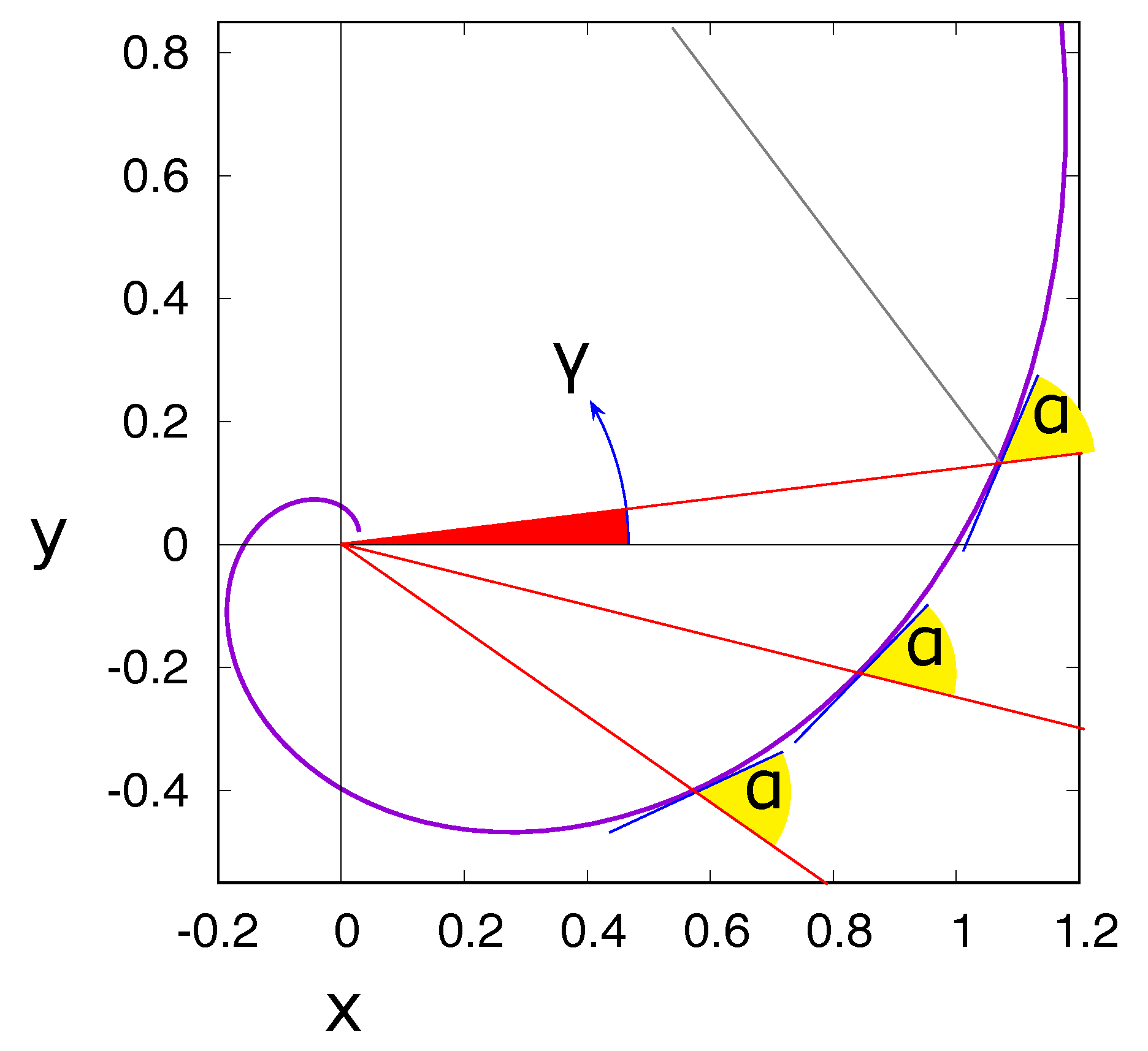
A basic feature of a logarithmic spiral (or equiangular spiral) is that all straight lines originating from the spiral pole intersect the spiral at any junction with the same angle
(see
Figure 1). The parametric representation of the spiral is
with the polar angle
and
one of the junctions with the
x-axis.
For
of the order of
, which are typical cut-off angles of total reflections for neutrons, one can locally approximate the spiral with the function
where
is the intersection of the spiral with the
x-axis.
Thus, a spiral-shaped mirror reflects all neutrons emerging from the spiral’s pole with the same angle. These neutrons intersect the spiral again further out with a smaller angle of incidence. Assuming an ideal coating of the surface, this is repeated until the reflecting surface ends. These garland reflections on the concave side of the spiral lead to a reduced beam divergence and, at the same time, the beam gets broader. This is illustrated in
Figure 2. For a very large number of reflections, one would obtain a wide and close-to-parallel beam. This is also true for a not-point-like source of neutrons, but would require more reflections.
We have previously used this property of the spiral to manufacture a transmission neutron polarizer with a spiral-shape polarizing supermirror for the case of a neutron beam emerging from a narrow region and with a large divergence. At any intersecting point of the beam with the polarizing surface, the conditions are similar, which enables an optimized coating design [
9].
For a (converging) neutron guide, the idea is now to reverse this process: A broad beam of low divergence is fed into a spiral-shaped neutron guide far from the pole and is then guided by a series of garland reflections towards the pole (see
Figure 2b). As long as the angle of incidence
is significantly smaller than
, the individual neutron is reflected on the guide wall. If
, the neutron goes straight to the pole, and, for angles
, it ends up close to the pole. The size and homogeneity of the beam spot at the pole is a function of the guide length. At this point, no zigzag trajectories are taken into account and the guide has no inner wall.
The phase space transformation of a spiral guide is illustrated in
Figure 3.
Figure 3a shows the intensity vs. direction (
) diagram for a wide incoming divergence
and various widths of the region of interest. As is expected, for a given
, the intensity increases with the width of the region. Furthermore, wider regions also accept larger
.
Figure 3b shows the intensity vs. directions diagram for the example of a 5 mm wide region of interest for various incoming rectangular divergences
. For
, the angular distribution of the trajectories reaching the sample is highly structured, but already covers a range of
. Increasing
leads to a moderate increase in angular spread on the sample and a rapidly growing total intensity. However, already for
, a smooth and across
a homogeneous distribution is reached. In other words, for a realistic incoming divergence, the phase space is largely homogeneous in the region of interest and therefore suitable for neutron experiments. For an incoming divergence higher than
, the intensity does not increase anymore, i.e., all additional trajectories miss the sample. This illustrates that the spiral guide preferably transports the low-divergent part of the incoming beam to the sample, while the higher divergences are lost or illuminate the sample environment.
3. Adaptation to the Situation at AMOR
In the context of replacing all cold neutron guides at the Swiss spallation source SINQ at the Paul Scherrer Institute in 2019, a conceptual study was performed for the reflectometer AMOR to be equipped with a Selene guide, optimized for small sample volumes. The upgrade of SINQ maintains the lay-out of the in-pile section (the first part of the guide reaching from
to
from the cold neutron source), and it allows for only minor changes of the location of the instruments in the experimental hall. These constraints, together with the layout of the neutron guide bunker, led to two competing approaches for the new guide of the reflectometer: (1) A Selene guide with the first focal point at the end of the in-pile section and the final focal point at the sample position outside the neutron guide bunker,
further down [
10] and (2) an alternative approach with a quite short Selene guide close to the sample [
11]. The distance between the in-pile section and the virtual source for the Selene guide would be bridged by a converging guide of logarithmic spiral shape, where the pole of the spiral defines the position of the virtual source for the Selene guide.
In the end, it was decided to realize the full-scale Selene guide, so that the concept of the spiral guide presented here is not fully optimized. Nevertheless, the investigated spiral-shaped guide shows some advantages over the traditional circular guide with constant cross section and might be of interest for future projects.
The general requirements for the new guide were:
The maximum cross section of the in-pile section is limited by the space available to .
The maximum region of interest at the end of the spiral guide was defined to be . These values are dictated by the subsequent Selene guide.
The distance from the entry to the virtual source location was .
The bunker side wall and ceiling allowed for a maximum offset of the guide exit of relative to the axis of the in-pile section.
The beam direction behind the guide dictates the orientation of the instrument, so that additional constraints applied there.
Our ansatz was to use a guide with a constant rectangular cross section, which is horizontally curved. The outer wall follows the shape of a logarithmic spiral, the inner wall is parallel to it, and the pole of the spiral coincides with the first focal point of the Selene section.
4. Monte Carlo Simulations
The Monte Carlo simulations presented here have been obtained using McStas v.2.3 [
12,
13] and followed the constraints laid out in the previous section. The flux on a
region of interest is evaluated. The set-up consists of a source emulating the SINQ cold spectrum for wavelengths between
Å and
Å. The incoming divergence is set by a first,
long straight guide (the in-pile section) of
cross section, coated with an
supermirror.
The 27 m long spiral guide is made from 270 straight rectangular pieces of length each. The physical guide ends in front of the pole of the spiral. The cross section of the guide is , similar to the feeder, and the individual rectangular pieces are arranged such that the outer wall follows a logarithmic spiral with . This angle is chosen in order to obey the geometric restrictions given by the SINQ guide bunker and experimental hall. A supermirror coating of is therefore largely sufficient to transport the intended wavelength range of 3.5 to 12 Å.
The direct line-of-sight of the guide itself is an important parameter when designing a beamline. The circular guide used for comparison is bent such that the direct line-of-sight ends just at the end of the curved section. The spiral guide is out of direct line-of-sight
before the guide ends; see also
Figure 2c. This property is largely influenced by the guide width and the characteristic angle of the spiral,
.
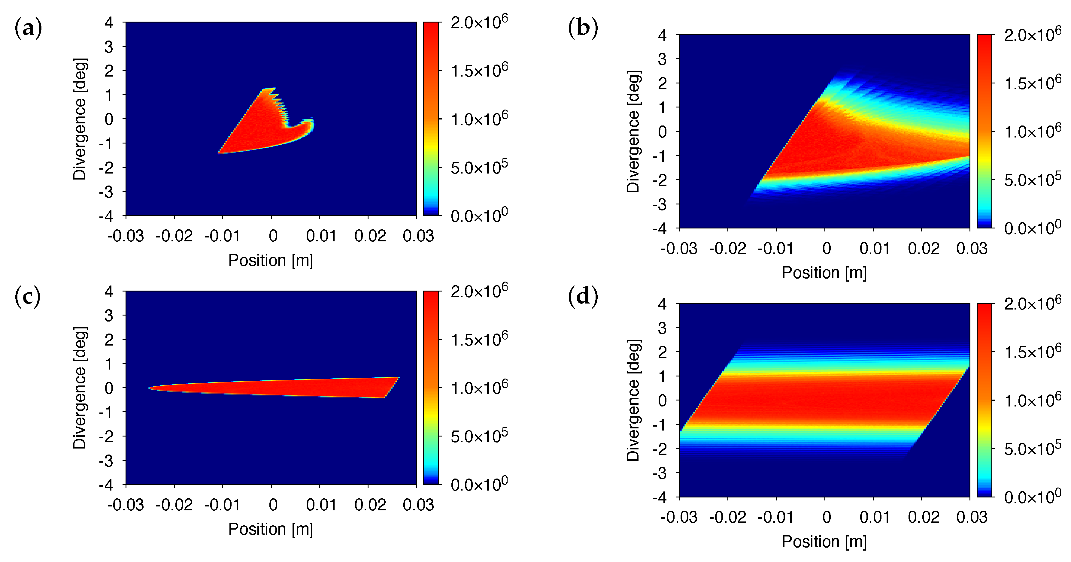
Two cases are considered in order to distinguish the contribution of garland and zigzag reflections to the beam spot: The coating of only the outer curve (a), therefore only allowing garland reflections and the coating of both inner and outer curve (b), which allows both zigzag and garland reflections.
Figure 4 shows the related position-divergence diagrams obtained on a plane almost normal to the beam at the pole of the spiral, later referred to as the "pole plane". The circular reference guide also shown in the figure has a bending radius of
and a cross section of
. For the simulation, it is truly bent. The performance of the two guides are compared and evaluated for a region of interest of
. To facilitate the discussion, we also distinguish the coating of the outer face only (c) and both faces (d) in the case of the circular guide.
In both cases, (a) and (b), a distinct, feather-like pattern is observable for the spiral guide. This is due to the approximation of the logarithmic spiral by line segments. The sharp edge on the left side of the intensity distribution is due to the shadowing by the end of the guide. Its inclination results from the beam broadening between the end of the guide and the pole. On the right side, the converging properties of the guide become apparent. When contrasting the two cases, it is evident that the garland reflections are mainly responsible for converging the beam. Zigzag reflections increase the flux some but also broaden the beam significantly.
Figure 5 shows the horizontal beam distribution at the pole plane for both guide geometries. One can clearly distinguish the beam characteristics: A broad, flat distribution for the circular guide and a peaking distribution with less integrated intensity for the spiral guide. Within the region of interest, the intensity in the latter case is 30% higher.
Table 1 gives more detailed information about the contribution of the inner guide wall: While the main transport of neutrons takes place via garland reflection, the table shows that the zigzag reflections are driving the gain above 1. This gain originates from the beam condensing properties of the spiral guide. In contrast, the geometry of the reference guide is non-converging. The circular guide presents lower divergence and a more uniform divergence distribution over the horizontal position, while the spiral guide leads to a more localized and therefore more divergent beam, as shown in the phase space diagrams of
Figure 4. There are, of course, various ways to introduce focusing elements in the circular guide geometry that would lead to gains of the same order.
Figure 6 reports the relative spectral transmission of the two guides for the realistic case as encountered for a spectrum after the in-pile section at SINQ. The transmission from the
incoming beam to the
region of interest is evaluated. For the circular guide, the transmission below the ideal-case 1% is due to losses by reflection on the supermirror coating. Indeed, for longer wavelengths, the transmission increases. For the spiral guide, the order of magnitude of the transmission is similar but varies in shape. The transmission of the spiral guide, in particular in the one-side coated case, seems favorable to shorter wavelengths. This is due to the normalization by the incoming spectrum which is shaped by the guide up-stream of the spiral guide, i.e., the in-pile section: For smaller wavelengths, only low divergences get transported and are entering the spiral guide. Low divergent neutrons are preferably transported by the spiral guide, (also see
Figure 3). Longer wavelengths enter also with higher divergences, but those are less likely to be transported downstream.
For the circular guide, this does not matter in the relative evaluation, since the coating is of the same quality as in the in-pile section. There, the transmission slightly increases for a longer wavelength due to better reflectivity of the coating at those energies. The realistic spiral guide, where both sides are coated, is a combination of the two effects with the zigzag reflections resembling the behavior of a simple circular guide plus the higher transmission of short, low-divergent wavelengths.
5. Discussion
Thus far, we have presented the expected performance of a spiral guide adapted to the situation at SINQ. With some further optimization, it might be possible to further increase the gain compared to the reference guide:
Firstly, we did not investigate the effect of the guide width being reduced towards the pole. If the width follows the caustic of the garland trajectories (the grey area in
Figure 2), the garland transport is not altered, but the zigzag trajectories are more confined and directed closer towards the pole.
Furthermore, the guide coating is not optimized in the data presented. One can expect that a lower m is sufficient further away from the pole where the angles of incidence are smaller, i.e., below . Given that the spiral guide essentially transports only the low-divergence part of the incoming beam to the region of interest, the coating of the in-pile section could also be lowered to transport divergences only up to the order of . Low coating is desirable for the budget and partial background reasons.
More generally, while we have investigated the spiral guide with regards to small samples,
Figure 5 suggests that, up to a width of the region of interest of some 25 mm, the spiral guide beats the circular guide in terms of total flux. This guide geometry therefore can be considered even for larger-sample instruments with the caveat that the phase-space homogeneity decreases with the size of the beam spot.
The fact that essentially only low incoming divergence is transported facilitates the addition of gaps particularly in the beginning of the guide, e.g., for choppers or shutters.
Moreover, the design presented effectively reshapes the phase space to a narrowed beam spot at the pole plane with only one to three reflections, as can be seen in
Figure 2c, which is plotted with the parameters of the spiral studied in this paper. The spiral guide therefore is very efficient in curving the beam out of direct line-of-sight on a relatively short distance. Indeed, direct line-of-sight is lost 4 m before the circular guide of similar length. In addition, the spiral guide results in a slightly larger offset of the beam with respect to the in-pile axis and at the same time in a higher inclination of the beam at its end. This feature can be attractive depending on the boundary conditions of the facility, in particular building walls and neighboring instruments.
Important points in comparing the guide concepts are the feasibility and the price. Manufacturing and installation of the individual guide elements for circular and spiral guides is almost the same: The latter will need more shorter elements towards the pole requiring more manpower for manufacturing and installation, but can accept longer elements further away. Since neither of them is a precision optical device, surface and alignment accuracy are of the same order. Thus, we expect no significant differences in total costs.
6. Conclusions
We have presented a qualitative study of the implementation of a neutron guide with the shape of a logarithmic spiral. The study has centered on the realistic use-case of a possible installation at a beamport of the SINQ neutron source at PSI. In comparison with a circular guide of similar cross section and coating, the flux gain of the spiral guide is roughly 30% in these conditions, with the spiral guide moving faster out of direct line-of-sight than the circular guide. The converging properties of the spiral are advantageous for reducing sample environment-caused background in proximity of the detector and related beam collimation efforts. For experiments that benefit from the resulting increased divergence, the use of a spiral guide thus provides a true alternative and is to be studied when designing the beamline. Ultimately, the spiral guide is a new element for the construction kit of neutron guides.


