Article

GeV-Class Two-Fold CW Linac Driven by an Arc-Compressor

1
Istituto Nazionale di Fisica Nucleare (INFN), Via Celoria, 16, 20133 Milano, Italy
2
Elettra-Sincrotrone Trieste S.C.p.A., 34149 Basovizza, Italy
3
Department of Physics, Università degli Studi di Milano, Via Festa del Perdono 7, 20122 Milano, Italy
*
Author to whom correspondence should be addressed.
Instruments 2019, 3(4), 54; https://doi.org/10.3390/instruments3040054
Submission received: 29 July 2019 / Revised: 2 October 2019 / Accepted: 6 October 2019 / Published: 10 October 2019
(This article belongs to the Special Issue Physics and Applications of High Brightness Beams)

Abstract

:
We present a study of an innovative scheme to generate high repetition rate (MHz-class) GeV electron beams by adopting a two-pass two-way acceleration in a super-conducting Linac operated in Continuous Wave (CW) mode. The beam is accelerated twice in the Linac by being re-injected, after the first pass, in opposite direction of propagation. The task of recirculating the electron beam is performed by an arc compressor composed by 14 Double Bend Achromat (DBA). In this paper, we study the main issues of the two-fold acceleration scheme, the electron beam quality parameters preservation (emittance, energy spread), together with the bunch compression performance of the arc compressor, aiming to operate an X-ray Free Electron Laser. The requested power to supply the cryogenic plant and the RF sources is also significantly reduced w.r.t a conventional one-pass SC Linac for the same final energy.

1. Introduction

This paper reports a study on high brightness GeV-class Super Conducting (SC) linear accelerators based on a new scheme named two-pass two-way. In this scheme a low emittance electron beam, at about 100 MeV, is injected into a SC linac booster, then the beam enters an arc compressor that has two objectives: (1) the bunch compression with the low emittance preservation and (2) the beam U-turn that makes it possible to accelerate a second time into the SC linac booster. This two-pass two-way acceleration concept gives the possibility to significantly reduce the machine footprint, as the AC power requirement and adds considerably to the compatibility of such kind of installation with typical university campus layout. Further, it strongly improves the sustainability of large-scale facilities where multi-GeV high beam power linacs are envisaged. Other than high brightness Gev-class electron beams, machines based on this scheme are suitable to work in Continuous Wave (CW). This makes it possible, considering for example free electron lasers (FEL), to pass from tens of kHz to MHz orders rep rate; e.g., the highest rep rate nowadays obtained is the one of the XFEL machine, at Desy in Hamburg, which reaches 30 kHz.
It is well reported in literature [1] that a 1 MHz rep rate is an ideal value for spectroscopy experiments conducted with X-ray FEL pulses; other relevant beam parameters for these kind of experiments, from electrons beam point of view, are: 2–4 GeV beam energy, 10–50 pC bunch charge, rms normalized transverse emittance lower than 0.5 mm-mrad, relative energy spread lower than 5 × 10 - 4 and current peak ranging in 1.5–2.0 kA; parameters considered at the FEL undulator entrance.
The work is organized as follows: in Section 2 we discuss the machine layout with the needed devices to achieve this peculiar acceleration scheme. In the Section 3, as proof of the scheme itself, we present a start-to-end (S2E) simulation, from the electron gun up to the end of the electron acceleration, focusing on the aim to drive an X-ray FEL. The FEL performances for this scheme are already reported in Reference [2]. The conclusions will focus on the possible outcomes of this innovative acceleration layout.

2. Machine Layout

The idea of two-way acceleration is not completely new: in Reference [3,4] the concept of beam re-circulation and re-injection for a second pass was proposed; the use of an arc compressor preserving the high brightness of an electron beam was presented in the seminal work in Reference [5], however no studies using an arc for both the bunch re-circulation and the bunch compression were already presented from other groups or labs.
In the layout presented in this study we named the arc compressor, due to its shape, as bubble arc compressor (BAC). A detailed machine layout, not at scale, thought to drive an X-ray FEL is presented in Figure 1.
The project study started with an accurate analysis of the CW or highest rep rate electron guns nowadays available. This analysis, mainly based on beam dynamic simulations, concluded by comparing a 300 kV DC gun and a RF VHF (185.714 MHz) RF-gun. Although the DC gun showed good performances, for our purpose, to drive an X-ray FEL, the RF gun with a highest cathode electric field peak and a highest beam energy at the exit was preferable. Therefore, the gun presented in this work is a VHF RF gun like the APEX-I [6], working with a Cs 2 Te phothocathode [7,8,9], driven by an Yb:Yag IV harmonic laser pulse (257.5 nm), at 1 MHz rep rate.
Downstream the gun, an injector accelerates the beam, setting the final machine performance in terms of brightness. The scopes of the two-pass two-way acceleration are to strongly compress an electron bunch and to “quasi” double its energy, exploiting the linac booster two times, the whole preserving the injector exit emittance. Injector high brightness performances are not strictly necessary and are clearly relative to the final project purposes. In the next chapter S2E we propose a case for an X-ray FEL source, and as stated above in the introduction, we need an emittance lower than 0.5 mm-mrad and a current peak in the range of 1.5–2.0 kA. These objectives were fully reached by the injector. The two-pass two-way acceleration carried out by following step by step the Figure 1 layout:
  • The injector about 20 m long is composed as follows: a 1.3 GHz normal conducting NC two 2-cells buncher; a cryomodule about 3 m long with inside a 7-cells 1.3 GHz acceleration cavity, a 3-cells 3.9 GHz higher harmonic cavity, for longitudinal phase space (LPS) shaping, and a second 7-cells 1.3 GHz cavity, at the cryomodule exit the bunch is pre-compressed and with an energy of about 6 MeV; an about 1.5 m drift used for emittance compensation; a 1 m 9-cells TESLA-like cavity where the bunch is accelerated at 10 MeV and undergoes a mild velocity bunching VB [10,11]; a TESLA-cyomodule, bringing eight 9-cells cavity that damp the last emittance oscillation and deliver a ∼130 MeV high brightness bunch.
  • Downstream the injector, a dogleg line brings the beam to the linac booster. In this line, if needed, a laser heater device to suppress the microbunching instabilities (MBI) [12,13] can be hosted. The MBI driven by coherent syncrotron radiation CSR and longitudinal space charge LSC in the bubble arc has been preliminarily evaluated, resulting in a moderate effect and not a show-stopper for lasing.
  • The Linac booster, 10 TESLA-like cryomodules for about 125 m, provides an energy increase up to 1.6 GeV. The injection phase that guarantees the correct chirp ad hoc for the R 56 of the BAC maximum compression is about 6 degree out of the RF crest.
  • Downstream the Linac there is a 3.9 GHz TESLA linac (named HHL into Figure 1), which is used to give an extra LPS RF curvature needed to pre-compensate CSR effects arising into the BAC.
  • The quadrupole matching line between the main linac (L1) and the BAC (10 quadrupoles) exploits the symmetric focusing effect of a SC solenoid [14] positioned before HHL. This quadrupoles matching line, being crossed back and forth by bunches, has not a trivial behavior. If it is not properly set considering the returning bunch dynamics, it increases the bunch transverse size, turning on chromatic effects that inside solenoids scale quadratically with the bunch dimension. This effect, if not kept under control, is very detrimental in terms of emittance increase. Consequently, the quadrupoles accomplish two tasks: to match the bunch to the BAC and to constraint the beam envelope within acceptable limits when, coming back, it enters a second time the SC solenoid.
  • The BAC is a long dispersive path used to increase the beam current peak while it is U-turned, preserving the transverse slice emittance, even in the presence of important Coherent Synchrotron Radiation (CSR) emissions. The lattice arc is based on the work described in [5]. It is composed by 14 Double Bend Achromat (DBA) cells, each one bending the beam of 30 ; Table 1 contains its main parameters.
  • After the BAC, where the bunch shows a current peak up to 100 times higher, it passes a second time into the qudrupoles matching line, into the SC solenoid and finally it is accelerated a second time by the SC linac booster in the backward direction overpassing 3 GeV energy.
  • Leaving L1 on the way back, the bunch enters two extra cryomodules, named L2, needed to tune the final beam energy (±300 MeV) before the beam is matched to undulators. A quadrupoles triplet before L2 provides a soft focuses kick that brings the beam rms transverse size at few tens of microns at the FEL undulators transfer lines entrance.

3. Start to End Simulation and Results

This S2E aims to the production of an electron bunch ad hoc to drive an X-ray FEL, therefore good beam parameters are needed at the injector exit, particularly a normalized rms emittance value lower than 0.5 mm-mrad, considering further the MHz rep rate requirement.
High gradient room temperature guns [11,15,16,17] are ruled out by their low rep rate operation (100–120 Hz) and consequently the injector (see the previous chapter) is based on the APEX-I gun. The non-trivial beam dynamics manipulation needed to reach the ad hoc beam parameters has been carried out by using the software GIOTTO, which is based on a genetic algorithm [18] and the macro-particles tracking code Astra [19], which considers space charge effects, mainly affecting the beam dynamics injector regions at low energy. Relevant beam parameter values at the injector exit are reported in Table 2.
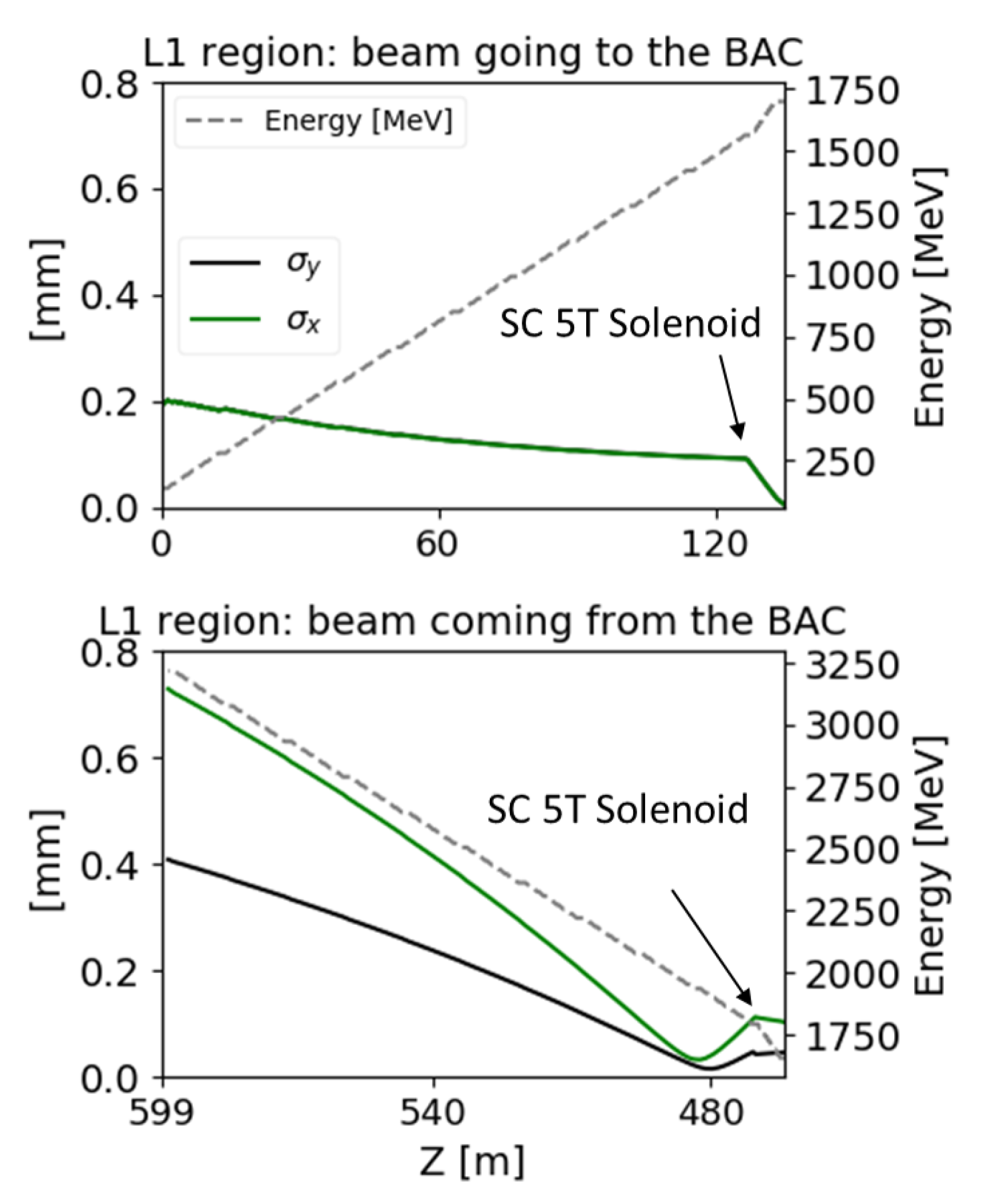
The simulation of the linac booster (L1 region in Figure 1), but also up to the end of the machine, has been done with the code Elegant [20], which tracks particles by using tracking matrices and can compute different collective effects, as the CSR emission and the longitudinal space charge effects, which are treated as impedances in a 1D model (only a longitudinal charge distribution). In Figure 2 the upper plot shows the beam envelope in the first pass through L1 with its energy gain: The beam remains round thanks to the RF and the solenoid focusing effects.
In two-pass two-way transport lines, the use of quadrupoles, although possible, can be critical; one single quadrupole shows inverse focusing for bunches that propagate in opposite directions. In this study we used quadrupoles only for the matching section between L1 and the BAC taking advantage of standing waves (SW) cavities RF focusing effect that is more effective than in traveling waves (TW) cavities. The net focusing effect of SW vs TW cavities, on 130 m booster length, is two times stronger. Furthermore, the focusing provided by a short SC 5T solenoid, similar to the one reported in [14], brings the beam beta function at values close to the BAC matching ones; in this way the quadrupoles of the L1 to BAC matching line work with low gradients, and the line itself is short (∼13 m), considering GeV class machines dimensions.
Along the linac booster, where all the main beam quality parameters remain unchanged, the beam is accelerated with a shifted of + 6 w.r.t. the RF crest to provide the correct longitudinal phase space chirp for the BAC compression.
The L1 to BAC matching line must carry out two different tasks depending on the direction of beam propagation. It makes use of 10 quadrupoles to properly address those tasks, each one is 35 cm long. The optimization is done in order to obtain the target values in Table 3 at the end of the line considering both the propagating directions.
The simulation of the BAC performed with Elegant takes into consideration important collective effects such as longitudinal space charge (LSC) and coherent synchrotron radiation (CSR). The final bunch current peak might drastically decreases if these collective effects are not adequately compensated. LSC and CSR effects have been simulated using a bunch populated with 10 6 macro-particles. The simulation result confirms the presence of strong CSR effects as expected, although no relevant signature of micro bunching instability induced by the secondary interaction of the emitted radiation with the bunch head was observed.
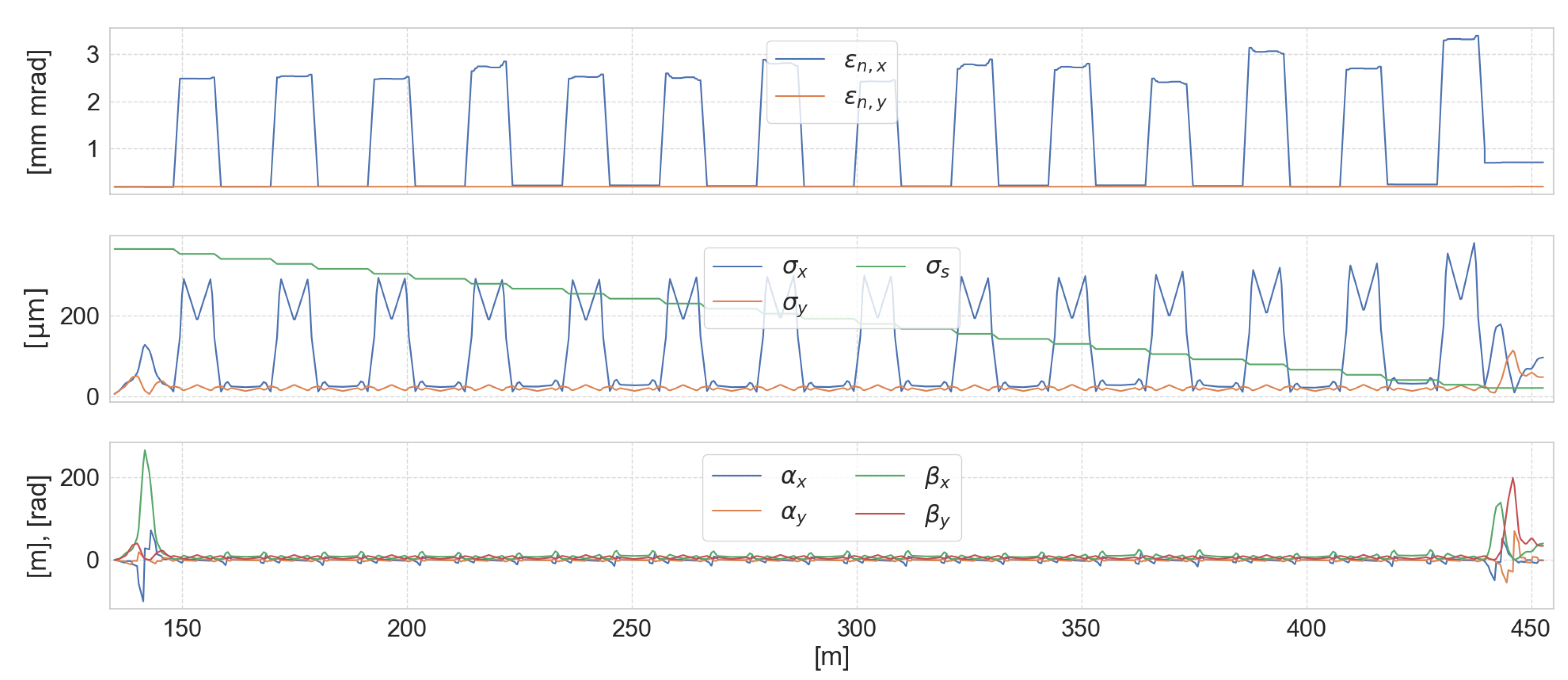
Figure 3 shows the trend of the main beam parameters within the section composed by the transfer line, the compressor arc and again in the transfer line (this time traveled backwards). The pre-compensation of the distortion effect induced by the BAC CSR emission exploiting the HHL in accelerating phase allows to linearize the LPS during the compression itself, this allows to reach a final current peak of about 1.6 kA (a relevat factor larger than 100) and a remarkably high brightness peak of about 9 × 10 16 A / mm - mrad 2 thanks to the emittance preservation. Figure 4 shows the LPS at the BAC exit with and without the pre-compensation effect of the HHL.
Table 4 shows the final beam parameters obtained after the second passage in the transfer line, i.e., after the optimization of the beam dynamics in the BAC.
Downstream the BAC matching line, the returning bunch travels throught the linac booster for the second time. The beam envelopes and energy gain for the two passages are shown in Figure 2, pointing out a BD comparison for the two beam directions. The SC solenoid effect is evident at the entrance of the line, in the second passage, where the beam is overfocused to few tens of microns. Then the bunch naturally defocuses and is partly kept under control by the focusing effect of the linac. At the end of the acceleration cycle, exiting from this second boosting phase, the bunch dimensions are about half a millimeter for both planes, and the emittance is kept constant along the whole booster second passage. The electron machine ends with two L-band cryomodules (Figure 1), a one-way region named L2 dedicated to a ±300 MeV final beam energy tuning upstream the undulators’ transfer lines. A triplet, one meter before the L2 entrance, focuses the beam bringing it down to few microns.
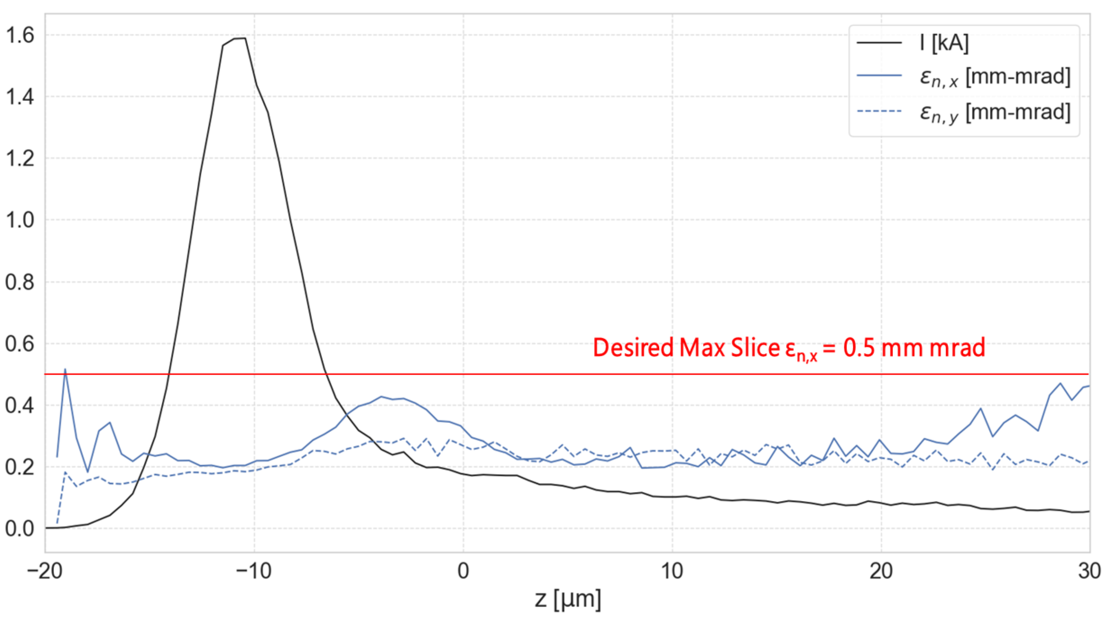
Figure 5 shows the bunch current slice distribution and the ϵ n , x , ϵ n , y emittances slices distributions at the end of the S2E considering the full bunch charge of 50 pC. The main beam parameters considering a cut of less than 40% of the total bunch charge, meaning to keep the large current spike on the left side of the Figure 5, are reported in Table 5.
These bunch parameters are aligned with the worldwide leading GeV class machine panorama in commissioning or already working [21,22], i.e., ad doc, to drive top class X-ray FEL radiators. It is worth mentioning that the electron beam brightness reported in Table 4 and Table 5 that is quasi conserved in the second passage in to L1 region and final energy adjustament in L2, is really outstanding [23].

4. Conclusions

The two-way SC CW linac new acceleration scheme promises to reduce construction and operational costs of large infrastructure or GeV class electron beam machines, allowing to conceive more compact research infrastructures compatible with a University Campus size. The possibility to locate the injector system alongside L2 (or undulators room) and the absence of magnetic compressors, typically 2–3 needed in conventional layouts, with a total length occupied by chicane elements equivalent to roughly half of the BAC, makes evident how the cost of the remaining optical elements and engineering costs are much lower than the cost of doubling the linac L1.
Further details concerning an X-ray FEL study exploiting this new paradigm can be found in the references related to the MariX project in the official website [24] or in its Conceptual Design Report [25].

Author Contributions

Conceptualization, A.B. (Alberto Bacci), S.D.M., L.F., M.R.C., A.R.R. and L.S.; methodology, A.B. (Angelo Bosotti), I.D., P.M., L.M., M.O., R.P., V.P., D.S.; software, A.B. (Alberto Bacci) and M.R.C.; writing–original draft preparation, A.B. (Alberto Bacci); writing–review and editing, A.B. (Alberto Bacci); supervision, L.S.

Funding

This research received no external funding.

Conflicts of Interest

The authors declare no conflict of interest.

References

  1. Young, L.; Ueda, K.; Gühr, M.; Bucksbaum, P.H.; Simon, M.; Mukamel, S.; Rohringer, N.; Prince, K.C.; Masciovecchio, C.; Meyer, M.; et al. Roadmap of ultrafast x-ray atomic and molecular physics. J. Phys. B At. Mol. Opt. Phys. 2018, 51, 032003. [Google Scholar] [CrossRef]
  2. Serafini, L.; Bacci, A.; Bellandi, A.; Bertucci, M.; Bolognesi, M.; Bosotti, A.; Broggi, F.; Calandrino, R.; Camera, F.; Canella, F.; et al. MariX, an advanced MHz-class repetition rate X-ray source for linear regime time-resolved spectroscopy and photon scattering. Nucl. Instrum. Methods Phys. Res. Sect. A Accel. Spectrom. Detect. Assoc. Equip. 2019, 930, 167–172. [Google Scholar] [CrossRef] [Green Version]
  3. Tigner, M. A possible apparatus for electron clashing-beam experiments. Il Nuovo Cimento (1955–1965) 1965, 37, 1228–1231. [Google Scholar] [CrossRef]
  4. Sekutowicz, J.; Bogacz, S.; Douglas, D.; Kneisel, P.; Williams, G.; Ferrario, M.; Ben-Zvi, I.; Rose, J.; Smedley, J.; Srinivasan-Rao, T.; et al. Proposed continuous wave energy recovery operation of an x-ray free electron laser. Phys. Rev. Spec. Top.-Accel. Beams 2005, 8, 010701. [Google Scholar] [CrossRef] [Green Version]
  5. Di Mitri, S.; Cornacchia, M. Transverse emittance-preserving arc compressor for high-brightness electron beam-based light sources and colliders. EPL Europhys. Lett. 2015, 109, 62002. [Google Scholar] [CrossRef]
  6. Wells, R.P.; Ghiorso, W.; Staples, J.; Huang, T.M.; Sannibale, F.; Kramasz, T.D. Mechanical design and fabrication of the VHF-gun, the Berkeley normal-conducting continuous-wave high-brightness electron source. Rev. Sci. Instrum. 2016, 87, 023302. [Google Scholar] [CrossRef] [PubMed] [Green Version]
  7. LASA Website. Available online: http://wwwlasa.mi.infn.it/ttfcathodes/ (accessed on 1 June 2019).
  8. Sertore, D.; Favia, D.; Michelato, P.; Monaco, L.; Pierini, P. Cesium telluride and metals photoelectron thermal emittance measurements using a time-of-flight spectrometer. In Proceedings of the 9th European Particle Accelerator Conference (EPAC), Lucerne, Switzerland, 5–9 July 2004; pp. 408–410. [Google Scholar]
  9. Vecchione, T.; Ben-Zvi, I.; Dowell, D.; Feng, J.; Rao, T.; Smedley, J.; Wan, W.; Padmore, H. A low emittance and high efficiency visible light photocathode for high brightness accelerator-based X-ray light sources. Appl. Phys. Lett. 2011, 99, 034103. [Google Scholar] [CrossRef]
  10. Serafini, L.; Ferrario, M. Velocity bunching in photo-injectors. In Proceedings of the American Institute of Physics (AIP) Conference, College Park, MD, USA, 28 September 2001; Volume 581, pp. 87–106. [Google Scholar]
  11. Ferrario, M.; Alesini, D.; Bacci, A.; Bellaveglia, M.; Boni, R.; Boscolo, M.; Castellano, M.; Chiadroni, E.; Cianchi, A.; Cultrera, L.; et al. Experimental demonstration of emittance compensation with velocity bunching. Phys. Rev. Lett. 2010, 104, 054801. [Google Scholar] [CrossRef] [PubMed]
  12. Huang, Z.; Borland, M.; Emma, P.; Wu, J.; Limborg, C.; Stupakov, G.; Welch, J. Suppression of microbunching instability in the linac coherent light source. Phys. Rev. Spec. Top.-Accel. Beams 2004, 7, 074401. [Google Scholar] [CrossRef] [Green Version]
  13. Qiang, J.; Ding, Y.; Emma, P.; Huang, Z.; Ratner, D.; Raubenheimer, T.; Venturini, M.; Zhou, F. Start-to-end simulation of the shot-noise driven microbunching instability experiment at the Linac Coherent Light Source. Phys. Rev. Accel. Beams 2017, 20, 054402. [Google Scholar] [CrossRef]
  14. Davis, G.; Kashikhin, V.; Page, T.; Terechkine, I.; Tompkins, J.; Wokas, T. Designing focusing solenoids for superconducting RF accelerators. IEEE Trans. Appl. Supercond. 2007, 17, 1221–1224. [Google Scholar] [CrossRef]
  15. Serafini, L.; Rosenzweig, J.B. Envelope analysis of intense relativistic quasilaminar beams in rf photoinjectors: MA theory of emittance compensation. Phys. Rev. E 1997, 55, 7565. [Google Scholar] [CrossRef]
  16. Ferrario, M.; Alesini, D.; Bacci, A.; Bellaveglia, M.; Boni, R.; Boscolo, M.; Castellano, M.; Catani, L.; Chiadroni, E.; Cialdi, S.; et al. Direct measurement of the double emittance minimum in the beam dynamics of the sparc high-brightness photoinjector. Phys. Rev. Lett. 2007, 99, 234801. [Google Scholar] [CrossRef] [PubMed]
  17. Bacci, A.; Alesini, D.; Antici, P.; Bellaveglia, M.; Boni, R.; Chiadroni, E.; Cianchi, A.; Curatolo, C.; Di Pirro, G.; Esposito, A.; et al. Electron Linac design to drive bright Compton back-scattering gamma-ray sources. J. Appl. Phys. 2013, 113, 194508. [Google Scholar] [CrossRef] [Green Version]
  18. Bacci, A.; Petrillo, V.; Rossetti Conti, M. GIOTTO: A Genetic Code for Demanding Beam-dynamics Optimizations. In Proceedings of the 7th International Particle Accelerator Conference (IPAC 2016), Busan, Korea, 8–13 May 2016; pp. 3073–3076. [Google Scholar] [CrossRef]
  19. Floettmann, K. ASTRA: A Space Charge Tracking Algorithm; DESY: Hamburg, Germany, 2017. [Google Scholar]
  20. Borland, M. Elegant: A flexible SDDS-Compliant code for accelerator simulation. In Proceedings of the 6th International Computational Accelerator Physics Conference (ICAP 2000), Darmstadt, Germany, 11–14 September 2000. [Google Scholar]
  21. Galayda, J. The Linac Coherent Light Source-II Project. In Proceedings of the 5th International Particle Accelerator Conference (IPAC’14), Dresden, Germany, 15–20 June 2014; JACoW: Geneva, Switzerland, 2014. [Google Scholar]
  22. XFEL. DESY. Available online: https://www.xfel.eu/ (accessed on 1 June 2019).
  23. Di Mitri, S. Maximum brightness of linac-driven electron beams in the presence of collective effects. Phys. Rev. Spec. Top.-Accel. Beams 2013, 16, 050701. [Google Scholar] [CrossRef] [Green Version]
  24. The MariX Initiative Official Website. Available online: https://marix.eu (accessed on 1 June 2019).
  25. Serafini, L.; Rossi, G.; Abbracchio, M.P.; Bacci, A.; Bellandi, A.; Bertucci, M.; Bolognesi, M.; Bosotti, A.; Broggi, F.; Calandrino, R.; et al. MariX Conceptual Design Report. 2019. Available online: https://repodip.fisica.unimi.it/marix/MariX_CDR.pdf (accessed on 1 June 2019).
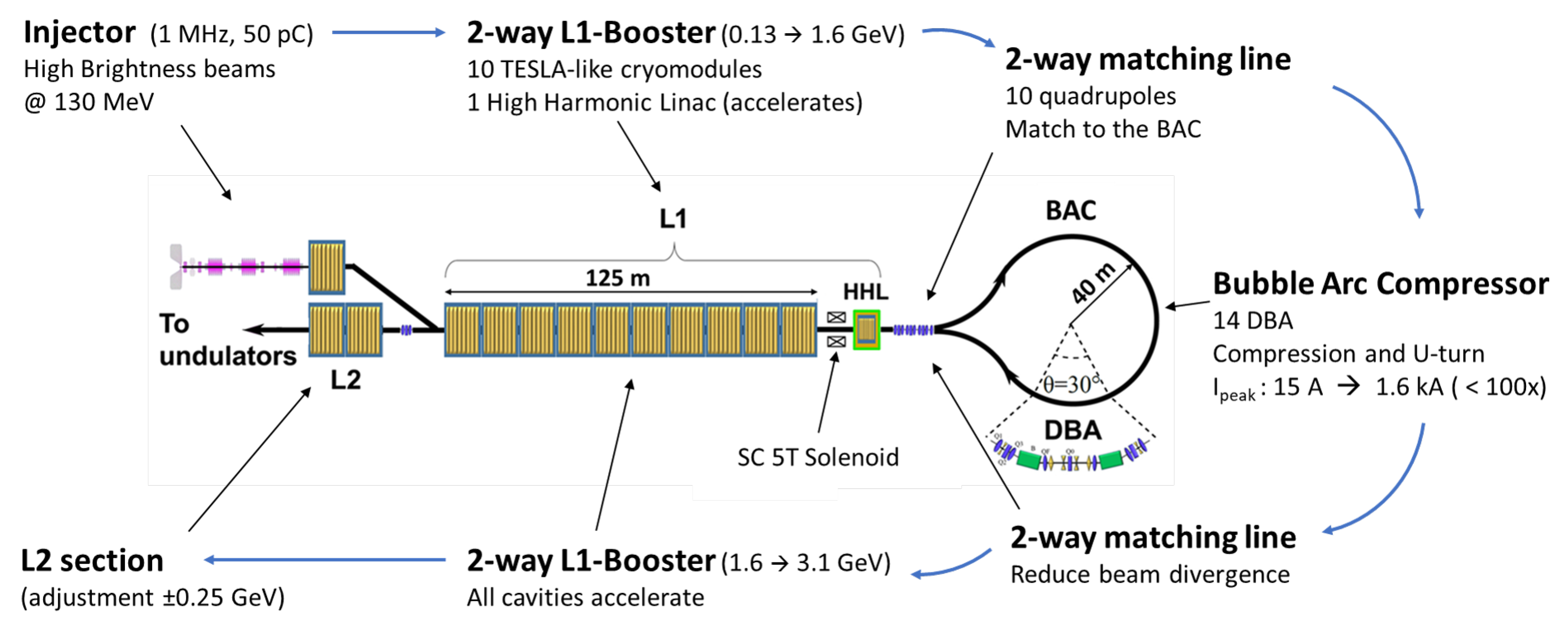
Figure 1. A high brightness injector delivers the beam to the booster linac (region L1) through a dogleg. L1 ends with a high harmonic linac (HHL); then, the beam enters the bubble arc compressor (BAC) used to compress and to perform the beam u-turn. The beam is re-accelerated in L1 and is finally energy-tuned in the linac L2.
Instruments 03 00054 g001
Figure 2. The upper plot shows beam envelopes and energy gain in the L1 region. The lower plot exhibits same parameters for the way back beam during the L1 region second passage. The RF ponderomotive and solenoid focusing effects, unchanged for the two different directions, perfectly control the beam envelopes in both directions.The second pass in L1, envelopes
Instruments 03 00054 g002
Figure 3. Main parameters of the bunch in simulations of the two passes trough the matching line and the arc compressor in presence of LSC and CSR effects. Top: transverse normalized total beam emittances. Middle: longitudinal and transverse beam envelopes. Bottom: main Twiss parameters.
Instruments 03 00054 g003
Figure 4. LPS at the BAC exit. In green the case where the CSR effect is pre-compensated by the HHL, in blue a test case with the HHL turned off. On top of the image the relative current profiles.
Instruments 03 00054 g004
Figure 5. Slice analysis of the current distribution and of the emittance for both the transverse planes. In red the maximum acceptable emittance value, set at the beginning of this study
Instruments 03 00054 g005
Table 1. DBA and BAC main parameters.
ParameterValue
Cell length 21 . 8 m
Dipole bending angle 15
Dipole length 1 . 4 m
R 56 per DBA cell35 mm
# of dipoles per DBA2
# of quadrupoles per DBA9
# of sextupoles per DBA6
# of DBA cells in the BAC14
Total R 56 in the BAC490 mm
Table 2. Main beam parameters at the injector exit.
ParameterValue
ϵ n , x - y 0.2 mm-mrad
σ z 365 μ m
E∼130 MeV
Table 3. Beam parameters obtained with the matching line after the first and the second passage.
PassagePar.Final val.
1st pass α x 3.179
1st pass α y 2 . 206
1st pass β x 2.152 m
1st pass β y 10.016 m
2nd pass σ x 2.02 × 10 6 rad
2nd pass σ y 1.19 × 10 6 rad
Table 4. Beam parameters at 2nd injection in L1. The slice parameters refer to a cut that keeps 31 pC of the 50 pC total bunch charge.
ParameterValue
σ s 20 . 6 μ m
σ x 96 . 6 μ m
σ y 47 . 2 μ m
ε n , x 0 . 70 mm mrad
ε n , y 0 . 20 mm mrad
γ 3050 . 6 ( E 1 . 56 GeV)
Q tot 50 pC
I peak 1 . 6 kA
Δ E E 1 . 0 × 10 3
Slices @ I peak ε n , x 0 . 2 mm mrad
Slices @ I peak ε n , y 0 . 2 mm mrad
Slices @ I peak B n 8 × 10 16 A ( mm mrad ) 2
Table 5. S2E final beam parameters relative to the most populated region of the bunch, representing the 62% of the whole bunch charge.
ParameterCut Bunch 31pC
σ s 2 . 7 μ m
ε n , x 0 . 24 mm mrad
ε n , y 0 . 18 mm mrad
E 3 . 202 GeV
I peak 1 . 5 kA
Δ E E 2 . 8 × 10 4
Best Slice I peak ε n , x <0.2 mm mrad
Best Slice I peak ε n , y <0.2 mm mrad
Slices @ I peak B n 7 . 5 × 10 16 A ( mm mrad ) 2