Review

Laser Technology in Photonic Applications for Space

by
Denis Guilhot
1,* and
Pol Ribes-Pleguezuelo
2
1
Worldsensing, Viriat, 47 10th floor, 08014 Barcelona, Spain
2
Fraunhofer Institute for Applied Optics and Precision Engineering IOF, Albert-Einstein-Str. 7, 07745 Jena, Germany
*
Author to whom correspondence should be addressed.
Instruments 2019, 3(3), 50; https://doi.org/10.3390/instruments3030050
Submission received: 30 July 2019 / Revised: 2 September 2019 / Accepted: 9 September 2019 / Published: 11 September 2019
(This article belongs to the Special Issue Photonic Devices Instrumentation and Applications)

Abstract

:
The registered history of laser technologies for space application starts with the first laser echoes reflected off the Moon in 1962. Since then, photonic technologies have become very prominent in most technical development. Their presence has also dramatically increased in space applications thanks to the many advantages they present over traditional equivalent devices, such as the immunity against electromagnetic interference, as well as their efficiency and low power consumption. Lasers are one of the key components in most of those applications. In this review, we present an overview of the main technologies involving lasers that are currently deployed in space, before reviewing the requirements for lasers to be reliable in that environment before discussing the advantages and drawbacks of replacing standard technologies by newly developed photonic laser-based devices.

1. Introduction

The combination of coherent light, such as that of a laser, and the stringent requirements to implement new technologies in space allows for several applications in optical communication, illumination, target designation, and active remote sensing to demonstrate unprecedented results compared to previously used technologies. Moreover, the scientific advances of laser emitting technologies allow for the implementation of new devices and applications. In the past, only giants, such as the National Aeronautics and Space Administration (NASA), the Soviet Union (now Russia), the European Space Agency (ESA) and, more recently, the Japan Aerospace Exploration Agency (JAXA), China, and India, had the capacity to launch technology into space. Israel has now also entered the race, as have private companies, such as SpaceX, Virgin, Blue Origin, and SpaceIL. The recent boom of micro and nanosatellites, with volumes as small as one litre and weights below 1.5 kilograms [1], has enabled new actors to launch new devices into space [2] for Earth observation, communication, Internet of Things (IoT), and geolocation, among others [3]. Due to the market demands and new active players, the number of devices deployed in space is rising significantly. For example, the UK alone plans on launching 2000 small satellites by 2030 [4]. Thanks to the intrinsic advantages of photonic applications (bandwidth, mass, power consumption, and immunity to electromagnetic interference), many of the new deployments in space will include many new laser devices [5]. In this publication, we will review the principal laser-based photonic applications for space, focusing on their technological aspects.

2. Laser Devices

The first successful use of a laser for a space experiment was registered on 9 May 1962, as part of the Laser Lunar Ranging experiment [6]. Since the laser device was located on the Earth’s surface, it did not need to fulfill additional specifications required for space flights, such as mechanical stability, thermal shocks, and radiation resistance.
The story of laser operation in space started in 1971, when the Apollo 15 carried what would be the first laser outside Earth, a flash-lamp-pumped Q-switched Ruby laser built by the RCA Corporation and used for the Laser Altimeter experiment [7]. The first diode-pumped solid-state laser (DPSSL) to be sent into space was delivered in 1992 and launched as part of the Mars Orbiter Laser Altimeter (MOLA) in 1996; the laser used an Nd:YAG crystal as the active medium [8]. In November 2001, the use of semiconductor laser technology in space was reported for a direct laser application rather than pumping, when the world’s first laser-based optical data link connected the Artemis satellite from the ESA with the Centre National d’Études Spatiales (CNES) Earth observation satellite SPOT 4 [9], using GaAlAs laser diodes emitting at 0.8 μm. It is also worth highlighting the first laser pulse emitted on a planet surface other than the Earth on 19 August 2012, by the laser integrated in the ChemCam device installed on the Curiosity Mars rover, which used an Nd:KGW crystal DPSSL [10].
The constraints associated with laser operation in space are different from those in terrestrial applications. Thus, the lasers suitable for space applications need to present specifications, such as long lifetime, high efficiency, low susceptibility to optical misalignment and contamination, and unattended operation, among others. The best laser has to be selected depending on the requirements of the application and environment. Wavelength, repetition rate, peak power, pulse length, flexibility, maintainability, manufacturing cost, and operating cost are important parameters to take into account, but the environment is also essential, depending on whether the laser will be in the low atmosphere, in deep space, near the sun, or on another planet.
The following subsections will address the most commonly used types of lasers suitable for space deployment, together with some of their specifications, applications, and examples of real-life deployments.

2.1. Semiconductor Lasers

Semiconductor lasers have been studied and used for years in space applications. Some of their main advantages include operation under direct current injection, which provides high electrical to optical power conversion efficiency, but also long lifetime and high output power. Although their divergence, beam quality, and intensity noise are not suitable for all applications, they are also the preferred pump element for solid-state lasers (SSLs) and fibre lasers since their wavelength can be slightly tuned to achieve optimum absorption of the laser media, making them the cornerstone for laser technologies used in space applications. Many materials are being used, such as GaAs, InGaAs, InP, and InGaAsP. The two most common types of semiconductor laser are the edge-emitting laser (EEL) and the vertical-cavity surface emitting laser (VCSEL).

2.1.1. Edge-Emitting Laser (EEL)

EELs are the most common semiconductor laser devices. Thanks to their diode junction structure, these devices can transform electrical energy into light. Apart from SSL pumping, they are mostly suited to applications, such as information relay (inter and intra satellite), matter light interaction (spectroscopy and pyrotechnics), planetary exploration and monitoring, metrology, and sensors [11]. Some direct applications for which they are being used include, for instance, the autofocus system of the ChemCam laser [12] or the rendezvous sensor for the docking of the European Automatic Transfer Vehicle to the International Space Station (ISS) [13]. EEL have already been deployed in satellites, in deep space, and also on the Martian surface.

2.1.2. Vertical-Cavity Surface-Emitting Laser (VCSEL)

The VCSEL differs from the EEL in its manufacturing process but, more characteristically, in its beam emission. The output laser beam of a VCSEL is emitted perpendicular to the top surface. Due to the differences in the manufacturing and packaging processes, the devices have to be independently qualified for the missions. Moreover, VCSELs require less electrical power due to their low threshold. Already in early studies, VCSELs were identified as good candidates for space applications. Carson [14] , reported that, although several factors must be taken into account to optimise VCSEL lasers for space applications, they display better radiation resistance than their EEL counterparts. LaForge et al. [15], described in detail the possibility to use VCSELs as space multi-processors, as well as the issues they may exhibit when exposed to radiations. The publication focused on the implementation of devices for satellite missions in different orbits. Moreover, Ellmeier et al. [16], demonstrated the functionality of VCSELs in harsh environmental conditions, such as low vacuum. The aim of this last work was to demonstrate that these devices could be used in space missions, such as JUpiter ICy Moon Explorer (JUICE) 2022, where the devices must be operative for about 17 years and support severe amounts of radiation. Similarly, Chaudron et al. [17], presented in their study of 1550 nm VCSEL devices the effects of temperature on different parameters of the optical device performances, such as optical output power, threshold current, and relative noise intensity.

2.2. Solid State Laser (SSL)

In this review, most of the SSLs that we will discuss are pumped by semiconductor diode lasers (DPSSL). SSL present several advantages over semiconductor laser, such as beam quality and the possibility to allow for extra versatility by reaching wavelengths and/or output powers which are not easily achieved by semiconductor lasers. In addition, short pulses can be emitted, for instance, through Q-switching, which are commonly used in range-finding applications. The space applications in which DPSSL lasers are used include Light Detection and Ranging (LIDAR) and spectrometer devices. An example of the former application would be the GEDI (Global Ecosystems Dynamics Investigation Lidar) instrument, developed for NASA’s Earth Venture Instrument (EVI) space program, which uses a version of the High Output Maximum Efficiency Resonator (HOMER) laser, an Nd:YAG crystal side-pumped by seven, 4-bar G-package laser diode arrays [18]. An example of the latter application would be the ESA/ROSCOSMOS ExoMars 2020 mission to Mars, that includes a Raman Laser Spectrometer (RLS) instrument whose excitation source is an intracavity frequency-doubled DPSSL emitting at 532 nm, shown in Figure 1, pumped by a CW (continuous-wave) Q-mount diode emitting at 808 nm [19].

2.3. Fiber Lasers

The development of fiber optics technology for telecommunications have resulted in new devices, including novel optical sources, which have also been beneficial for space applications. Some of the most interesting aspects for space applications include standard benefits, such as high power, cost, beam quality, and efficiency, but also more space-relevant improvements, such as unattended operation, compactness, low susceptibility to optical misalignment and contamination, thanks to their monolithic structure, low sensitivity to environment changes, and high reliability. Space-qualified pump and seed laser sources are also available for this technology. NASA has already demonstrated its relevance for remote sensing and laser altimeters, but other applications include LIDAR, metrology, telecommunications, and automated planetary rovers [20].
In 2009, the first fiber laser was launched into space within the Fiber Sensor Demonstrator for ESA’s Proba-2 satellite. One of the aims of this mission was to demonstrate the reliability of a full fiber-optic sensor network in space The device included a fiber laser that could sweep the wavelength range from 1520 to 1560 nm. The systematic monitoring of the demonstrator showed that seven years after the launch, the system was still working as expected [21].

2.4. Other Types of Laser Sources

Other types of lasers have been studied for space applications, such as gas, dye, and chemical lasers, but they present more difficulties to be adapted to space environments [11]. Common drawbacks include short lifetime and poor radiation resistance [22]. In particular, excimer lasers have lifetimes of less than 100 h due to the degradation of the gas charge, and ion lasers’ lifetime is less than 1000 h. Dye lasers are not robust and suffer from a low efficiency, and chemical lasers, such as hydrogen fluoride (HF) lasers, have short lifetimes limited by the fuel charge [23]. Variations of the lasers described in the current section might become relevant for space applications in the future, such as Quantum Dot semiconductor lasers, disc lasers, or photonic crystal fiber lasers. Lasers pumped by other means are also being studied; for instance, a solar-pumped laser was demonstrated in 1966 [24] and such devices have been considered since by both NASA [25] and ESA [26], as they would be extremely relevant in the space environment, although the deployment is not yet realistic due to the low maturity level of such devices.

3. Lasers in Space

3.1. Science

Although recent applications have been focused towards industrial usage of space technologies, several under way deployments are still catering to scientific purposes, aiming at increasing the knowledge regarding the history of the universe and the discovery of traces of potential life. In the following section, we will be addressing scientific objectives, before discussing more pragmatic matters, such as industrial application of space technologies.

3.1.1. Remote Sensing (LIDAR)

  • Earth Observation
The observer effect is a well-known physics phenomenon that states that observation of an experiment can alter some of its parameters, so remote, non-interfering characterization techniques can provide better objective information. In the same way, observing the Earth from space can provide better perspective, additional information, and a more global vision to study our planet. New services and information channels can be developed to solve challenges, such as deforestation, climate change effects, and pollution, as well as enable more sustainable processes for precision agriculture, fleet management optimisation, tree-harvesting, construction, and even mining, which can help humans live in better harmony with the planet. Thanks to recent improvement in satellites and the development of micro- and nano-satellites, it is now easier than ever to send experimental devices to orbit the Earth. Many examples of laser photonic devices and missions that have successfully studied our planet evolution from space have been reported, although the most common example is the space-based LIDAR, which sends laser pulses to the target surface and analyzes the reflected signal (schematic of its principle is shown in Figure 2).
The early laser LAser GEOdynamic Satellite (LAGEOS) NASA mission was launched in 1976. It was the first satellite dedicated exclusively to high-precision laser ranging, a passive experiment with ground emitter/receiver laser devices that could improve the current knowledge of our planet’s shape, and paved the way for the next satellite missions [28]. The mission had resemblances with the first 1962 Lunar Laser Ranging experiments, in terms of shooting at an object with a ground laser beam and waiting for the response signal. The results obtained using the orbiting mirror helped to prepare for future medium orbit satellite missions. It was followed in 1992 by the LAGEOS-2, which was designed by the Italian Space Agency, based on the original LAGEOS design.
NASA launched the LIDAR In-space Technology Experiment (LITE) mission on the Discovery Space Shuttle in September 1994 to validate key LIDAR technologies for spaceborne applications. LITE operated with a two-lasers system providing redundancy in case one laser failed, emitting at three wavelengths (1064 nm fundamental, 532 nm second harmonic, and 355 nm third harmonic) from an Nd:Cr:YAG laser crystal pumped by two flash lamps [29].
The BALKAN instruments were launched by Russia in 1995 and were also based on flash lamp pumped Nd:Cr:YAG crystals, frequency doubled in order to use the 532 nm wavelength [30].
In 1996 and 1997, the Shuttle Laser Altimeter experiment produced laser altimetry and surface LIDAR data as results of the test flights for transition of the technology to low Earth orbit [31]. The lasers on both flights were copies of the MOLA laser and, as such, were based on a passively switched Nd:Cr:YAG crystal producing 10 pulses per second with energies of 40 mJ and width of 10 ns at 1064 nm [30].
The ESA Envisat 2002 mission studied ocean and atmospheric chemical and physical composition, Earth topography, and the ice sheets, among other [32]. The mission could acquire data of about 4.6 Mbps that was later communicated through an X-band direct link to the ground [33]. The Envisat European mission is considered the predecessor of the Sentinel missions that are currently being deployed.
The Geoscience Laser Altimeter System (GLAS) Laser Transmitter, launched in 2003, was an Earth observation LIDAR whose main objective was the study of the Earth ice sheet mass. The device contained the first passively Q-switched, master oscillator power amplifier (MOPA) that worked in space, representing a one order of magnitude power improvement over the MOLA laser system [34]. The device designed with three redundant laser units produced a laser output of 75 mJ at 1064 nm with a repetition rate of 40 Hz, pulse width smaller than 6 ns, and they emitted just under 2 billion shots before the mission was completed in 2011 [35]. This output was used for altimetry. The lasers also simultaneously emitted at 532 nm pulses with 30 mJ energy, used for cloud and aerosol lidar [36].
In 2006, NASA launched the Cloud-Aerosol Lidar with Orthogonal Polarization (CALIOP) instrument inside the Cloud-Aerosol Lidar and Infrared Pathfinder Satellite Observation (CALIPSO) mission, jointly with the French National Centre for Space Studies (CNES). The objective was to provide new insight into the role that clouds and atmospheric aerosols, such as airborne particles, play in regulating the Earth’s weather, climate, and air quality [37]. CALIOP used two redundant Q-switched Nd:YAG lasers, and used three receiver channels, one at 1064 nm and two at 532 nm, measuring orthogonally polarised components of the backscattered signal. A pulse energy of 110 mJ per channel was used, at a 20 Hz repetition rate [38].
The ESA Sentinel missions started in 2014 with the launch of Sentinel-1A and will continue delivering monitoring satellites for at least another half a decade. The satellites battery includes different optical devices from mission control devices to Earth monitoring, through communication devices that study tectonic plates, the oceans, and emissions of gases, among others [39].
The Cloud-Aerosol Transport System (CATS) mission, which was launched in 2015, was installed on the ISS and used a two-laser LIDAR system, each of the lasers operating at three wavelengths (1064, 532, and 355 nm), to provide vertical profiles of atmospheric aerosols and clouds [40]. A ring oscillator design was selected and the pulse widths were, respectively, 8.2 ns and 5.3 ns at 1064 nm, with a pulse energy of 3 mJ [41].
The ESA Aeolus mission, originally planned to be launched in 2008 and mainly aimed at studying global wind profiles, will help improve significantly the weather forecasts. The mission, finally launched in 2018, uses a 355 nm UV pulse laser emission, resulting from frequency-tripling of a diode-pumped Nd:YAG crystal in a lithium triborate (LBO) crystal, to study the atmosphere composition and evolution [42].
In 2018, NASA also launched the ICESat-2 mission that includes an Advanced Topographic Laser Altimeter System (ATLAS) mostly used to study the ice-sheet topography. The ATLAS included two lasers and a MOPA able to deliver a pulsed beam frequency doubled to 532 nm through second harmonic generation, with a 1 ns full width at half maximum (FWHM) pulse width and 10 kHz repetition rate, split into six beams to create a pattern for better resolution of the application [43].
Water, mineral, and underground natural resources detection are studied in the GRACE-FO NASA mission launched in 2018 [44]. Laser ranging interferometry (LRI) is used to continuously measure the distance between the two satellites flying together. The acceleration and deceleration of the two separate bodies will provide information on gravitational changes, helping to understand the underground surface composition [45].
The Global Ecosystem Dynamics Investigation (GEDI), launched in December 2018, also participates in the Earth Observation effort by providing high resolution laser ranging of Earth’s forests and topography from the ISS. The device employs three laser transmitters emitting at 1064 nm at a 242 pulses per second repetition rate [46].
  • Other Solar System Targets
Similar devices to those described in the previous section have been successfully sent to study other bodies in our solar system. We highlight here some of these devices that have been sent to the Moon, Mars, and Mercury, among other targets.
The first topographic mapping of the Moon from orbit was performed by Apollo 15 in 1970, which was then extended by the Apollo 16 and Apollo 17 missions. The lasers were flash-lamp pumped based and mechanically Q-switched with a ruby laser emitting at 694.23 nm with a pulse energy of 200 nJ and a pulse width of 10 ns [35]. In 1994, the Clementine mission was launched, which mapped the surface of the Moon over a period of more than two months. It carried on board a compact, lightweight, diode-pumped Nd:Cr:YAG laser, emitting pulses of 180 mJ energy and 10 ns width at 1064 nm. The Q-switching was performed by a Lithium Niobate (LiNbO3) crystal-based Pockels cell [47]. SELENE, also known as Kaguya, was a Japanese mission launched in 2007 that orbited the Moon for more than one and a half years and surveyed it with LIDAR technology using an Nd:YAG laser with 100 mJ output power at 1064 nm, a pulse width of 15 ns and a repetition rate of 1 Hz. The Q-switch was also performed actively by a LiNbO3-based Pockels cell [48]. China also created a lunar exploration program called Chang’E. The first mission was launched in 2007 and the lunar surface was mapped between November 2007 and July 2008. The laser specifications were similar to those of previous missions, with an output wavelength of 1064 nm emitted from a diode-pumped Nd:YAG crystal actively Q-switched with a potassium dideuterium phosphate (KD*P) crystal. The energy emitted was 150 mJ per pulse and a pulse width of less than 7 ns at repetition rate of 1 Hz [49]. A similar laser was used for the Chang’E-2 mission launched in 2010, but with a repetition rate of 5 Hz. The resolution of the measurements was increased to achieve a 5 m vertical accuracy [50]. In 2008, India launched its first lunar probe called Chandrayaan, equiped with the Lunar Laser Ranging Instrument (LLRI) that mapped the surface topography using a Q-switched Nd:YAG laser at 1064 nm with a pulse energy of 100 mJ and a pulse width of 15 ns. The active Q-switching was also performed by an LiNbO3 crystal [30]. The NASA Lunar Orbiter Laser Altimeter (LOLA) was also launched in 2008, one of its objective being the validation of technologies for following missions to the Moon. It uses a DPSSL with an Nd:Cr:YAG slab with passive Q-switch and a cross-Porro resonator configuration working at 1064 nm, 28 Hz repetition rate and about 3 mJ at 5 ns for the both mounted redundant lasers [51,52].
The NASA DPSSL for MOLA was launched in 1996 with the objective of studying the Martian topography. The mission used a diode-pumped, Nd:Cr:YAG zigzag slab, cross-Porro, electro-optically Q-switched laser transmitter. The laser design parameters were 40 mJ energy with pulse width of 10 ns and repetition rate of 10 Hz, although the experimental data was closer to 45 mJ with pulses of 8 ns width [53]. In 2008, the PHOENIX lander, equipped with a LIDAR system, reached Mars. The dual wavelength Nd:YAG laser it carried was capable of delivering pulses with energies of 30 mJ at 1064 nm and 40 mJ at 532 nm after frequency-doubling in a KTP crystal with a pulse width of 15 ns at a repetition rate of 100 Hz provided by a saturable observer. The apparatus was used to study the Martian atmospheric dust, clouds, and precipitations, such as ice, fog, and snow [54].
The Mercury Laser Altimeter (MLA) on board of the NASA mission MErcury Surface, Space ENvironment, GEochemistry, and Ranging (MESSENGER) launched in 2004 is a passive Q-switched LIDAR laser operating with 5 ns and 20 mJ laser pulses at a 8 Hz rate used to gather topographic information of the planet. In this case, the configuration used a similar zigzag slab design, although in other aspects, its design had a direct linage from the GLAS laser passively Q-switched DPSSL [52,55]. The BepiColombo mission, launched in 2017 and set to build on the achievements of the MESSENGER mission, incorporates a space-qualified miniaturized laser operating at 1064 nm and a repetition rate of up to 10 Hz, based on a Q-switched Nd:YAG rod oscillator pumped by two semiconductor diode lasers [56].
A 1064 nm Nd:Cr:YAG laser rod pumped by a gallium arsenide laser diode array was used as one of the principal components for the Near-Earth Asteroid Rendezvous (NEAR) laser ranging investigation launched in 1996 by the NASA, which observed the asteroid 433 Eros between 2000 and 2001. A laser pulse width of 12 ns was achieved at 1064 nm using an Nd:YAG laser crystal, with an energy per pulse of 15 mJ [57]. In 2003, Hayabusa 1 was launched by JAXA to study the Itokawa asteroid. The LIDAR system was used in rendezvous and approach phases of the mission, but also provided important surface information of the asteroid itself. The spacecraft was equipped with a laser altimeter system based on a diode-pumped, Q-switched, single-mode Nd:Cr:YAG emitting 8 mJ energy pulses at 1064 nm, with pulse widths of 14 ns and a repetition rate of 1 Hz through the use of Lithium Niobate Pockels cell [58]. The laser for the following Hayabusa 2 mission was developed based on the lasers for Selene and Hayabusa 1, but the output pulse energy was increased to 15 mJ and the pulse width reduced to 7 ns [59]. Hayabusa 2 was launched in 2014 and rendezvoused in 2018 with the asteroid Ryugu. NASA’s Origins Spectral Interpretation Resource Identification Security–Regolith Explorer (OSIRIS-REx) mission was launched in 2016 to study the asteroid Bennu. It was equipped with the also called OSIRIS-REx Laser Altimeter system which is currently performing LIDAR measurements to provide high resolution topographical information of the asteroid. Two different Nd:YAG lasers operate at 1064 nm: a low-energy source operating at 10 kHz with a 10 μJ per pulse that can be used for rapid time-of-flight imaging down to 225 m and a higher-energy source emitting 1 mJ pulses at 100 Hz repetition rate to scan the asteroid at distances between 7.5 km and 1 km from the surface [60]. The OSIRIS-REx mission also plans to bring small samples from Bennu back to Earth. Finally, NASA’s JUICE mission, which will be launched in 2022 to study the icy moons of Jupiter (Ganymede, Callisto, and Europa), will also use two cold-redundant, transversely-pumped, actively Q-switched Nd:YAG rod laser emitting 17 mJ pulses at a repetition rate of 30 to 50 Hz with a pulse width of 5.5 ns and a wavelength of 1064 nm [61]. The design of the whole LIDAR system is based on the designs of the Kaguya and Hayabusa missions, as well as that of the BepiColombo Laser altimeter.
The examples above illustrate how a demonstrated and qualified laser configuration can be replicated with small updates to adapt the device to the specific requirements of following space missions in order to guarantee their success.

3.1.2. Spectroscopy

Spectroscopy is a very common analytic technique that can be used to probe the composition of an object. Thanks to the electromagnetic radiation emitted from a body, the resulting spectrum can be analyzed to infer the physical properties of that object, such as chemical composition, mass, and temperature. This emission signal can be amplified by exciting the target with the energy of a source. Both passive and active spectroscopy are useful in a wide range of scientific and industrial applications, but also in space applications where they have allowed, for instance, to confirm the expansion of the universe [62]. Many different types of excitation sources can be used for active spectroscopy, such as light bulbs, flash lamps, ion, electron, or X-ray beams, although a number of spectrometers rely directly on Solar light, such as the devices used in the Chandrayaan missions. Spectroscopy is also commonly used to study astronomical bodies and samples in laboratories. Here, we will concentrate on the space application of spectroscopy techniques that rely on lasers, such as Raman Spectroscopy and Laser Induced Breakdown Spectroscopy (LIBS).
In 2011, NASA sent the Curiosity Rover to Mars, which contained the ChemCam instrument that could analyze targeted samples composition up to 7 m away. The ChemCam LIBS instrument, one of the firsts of its kind launched in space, used a 1067 nm laser pulses of ≥10 MW/mm2 generated by an Nd:KGW crystal to create laser-induced breakdown, to later analyze the generated plasma thanks to the also incorporated spectrometer device [63]. The future NASA 2020 mission to Mars intends to use improved devices, allowing moreover to search and analyze organic compounds. To do so, the SuperCam instrument, apart from being able to perform LIBS analysis, counts also with Raman spectroscopy capabilities. To allow for both analyses, the laser device is designed with an Nd:YAG crystal instead of an Nd:KGW as its predecessor was [64]. The mission intends also to perform proximity Raman spectroscopy using a 248.6 nm beam emitted from a Neon-Copper Transverse Excited Hollow Cathode laser. The latter device will be installed in the robotic arm instrument called Scanning Habitable Environments with Raman & Luminescence for Organics & Chemicals (SHERLOC) [65,66,67]. Similarly, the 2020 ESA mission will carry the Rosalind Franklin rover, which includes the Mars Organic Molecule Analyser (MOMA) and the Raman Laser Spectrometer (RLS) instruments [68]. Both instruments, independently designed and manufactured, are based on different laser approaches. The MOMA uses a 266 nm laser with a tunable beam between 35 and 250 MW/cm2 generated from a frequency quadrupled beam from an Nd:Cr:YAG crystal [69,70], while the RLS instrument incorporates a DPSSL designed with an Nd:YAG crystal emitting an output beam frequency doubled to 532 nm [71]. The rover internal laboratories and lasers will analyze samples that will have been previously extracted from the Martian underground thanks to a mechanical drill incorporated on the rover.
Similar laser spectrometer devices will also be deployed in-situ, as, for example, on the Pragyan rover on the Chandrayaan-2 mission to the Moon. The mission is planned to be launched in September 2019 and will carry a LIBS device with an Yb:Er:Phosphate glass laser operating at a wavelength of 1534 nm, with pulse energies between 2 and 3 mJ and a pulse duration of 7 ns [72]. Other techniques, such as tuneable laser spectroscopy (TLS), have been used at the ISS and also incorporated in Mars missions for atmospheric composition analysis [73].
With the astonishing results obtained by the Curiosity mission and the great possibility of being able to analyze the composition of planets and space bodies in-situ, the interest of developing new laser spectrometer devices for future missions has arisen, such as the Standoff ultracompact micro-Raman sensor developed by Nuril Abedin et al. [74], for future planetary surface explorations.

3.1.3. Quantum Scientific Technologies

Scientific experiments addressing quantum physics challenges have also been launched into space. Atomic clocks and atom interferometers, which can be used for various space applications, are some of the devices that have been tested. Atomic clocks based on laser-cooled atoms are widely used as primary frequency standards and are a key component of the Global Navigation Satellite System (GNSS). Atom interferometers are used in applications described in the article of Schuldt et al. [75], such as measurements of the Earth’s gravitational field, gravitational wave detection, navigation, and tests of the weak equivalence principle. In the same paper, authors reported an atom interferometer device built with a laser system based on a hybrid approach using fiber-based telecommunication components and high-power laser diode technologies, designed in the framework of the space mission Space-Time Explorer and QUantum Equivalence Principle Space Test (STE-QUEST). The purpose of this mission is to perform quantum experiments to test the Einstein Equivalence Principle to a high precision level, as well as search for new fundamental constituents and interactions in the Universe [76]. Similar technologies were demonstrated in the Quantus project, and in rocket mission experiments, such as MAIUS and Kalexus. The first cold atom experiment in space was reported in 2017 with the Matter-Wave Interferometry in the Microgravity (Maius 1) mission [77], although it only lasted six minutes. The laser module was based on a MOPA configuration where the oscillator was built of a 1 mm long double quantum well, AlGaAs based ridge-waveguide distributed feedback diode laser emitting at 766.7 nm with a linewidth of approximately 1 MHz [78], and where a self-seeded tapered amplifier (TA) was used to generate an output power of more than 1 W [79]. The output power emitted through the back facet of the Distributed FeedBack (DFB) diode laser was monitored with a photo diode. Nevertheless, there has been some controversy on which experiment was performed first, since China started a mission called Cold Atom Clock Experiment in Space (CACES) in 2011 that resulted in launching an atomic clock in space in 2016, but the results were only reported one year later. In this case, the system used two input distributed Bragg reflector diode laser beams for laser cooling of rubidium [80].
The Cold Atom Lab experiment, launched to the ISS in May 2018, was designed and built at NASA’s Jet Propulsion Laboratory (JPL). It uses a very complex design based on commercial laser equipment and has successfully produced Bose-Einstein Condensates (BEC) of Rubidium atoms in orbit for the first time. Thanks to the microgravity conditions of the ISS, the BEC produced are colder and more stable, which should allow to observe new quantum phenomena and test fundamental laws of physics which could be applied in quantum detectors, optical clocks, and gravity monitoring. The light source consists in external cavity diodes, where a reference laser is used for each species: one at 766.701 nm, the other at 780.240 nm. The laser cooling system uses stabilized New Focus Vortex Plus diode lasers and New Focus TA-7600 tapered amplifiers [81].
Further atomic clock missions in space will include ESA’s Atomic Clock Ensemble in Space (ACES), which has been tested and integrated on the payload and will be ready for launch to the Space Station by 2020. The objective is to place atomic clocks in orbit and compare their performance to ground clock systems, as well as perform fundamental scientific experiments, such as gravitational red-shift and light anisotropy measurements, amongst others [82]. The cesium atomic clock system called PHARAO (Projet d’Horloge Atomique Par Refroidissement d’Atomes en Orbite), to be deployed within the ACES mission, has been developed by the CNES (Figure 3). The laser source is a commercial JDS 5421 master diode laser, based on the extended cavity laser diode (ECLD) concept and emitting 30 mW at 852 nm with a linewidth of 100 kHz and a single mode tunability of 1 GHz, that seeds two slave laser diodes for output powers of 100 mW [82].
The ESA’s Space Optical Clock on ISS (ISOC) mission, planned to be launched in 2022, will also include an atomic clock mainly for fundamental science measurements, such as the Earth, Sun, and Moon’s gravitational time dilation, clocks comparison in the line of the ACES mission, and search of Dark matter topological defect. The device will use several lasers at 461 nm, 689 nm, and 698 nm, but also commercial Toptica lasers at 679 nm and 707 nm for re-pumping and a lattice based on the ECLD/TA concept [83].
Finally, ESA is working on the LISA mission, planned to be launched in 2034, to detect and accurately measure gravitational waves using the so-called Laser Interferometer Space Antenna (LISA). In order to test the technology, the LISA Pathfinder mission was launched at the end of 2015. The reference laser unit used in the laser interferometer technology was based on a 35 mW Nd:YAG non-planar ring oscillator emitting at 1064 nm [84].

3.2. Communication

Historically, one of the major drivers for the development of photonic technologies has been telecommunications and the growing demand for high-speed communications. Previously, the most common data transmission technology relied upon in space was radio communication, although it reached its limit in the rate of data transmitted per second. Today, satellites, rovers, and other space devices use new data acquisition technologies, such as high-resolution cameras, microphones, and spectrometers, among others, which require much faster data processing and communication, for instance, in the case of photo or video transmission. The data must be sent to paired devices or Earth control with the minimum possible delay to adjust to missions’ requirements. A clear example of such a need is the current Martian rover missions, where the data acquisition and analysis help Earth-based scientists decide where to direct the rover next. Free space laser communication technologies have already demonstrated their potential for much faster data rates and, when combined with quantum technologies, much more secure communication channels. Nevertheless, these technologies still have to be space qualified [5] and approved for future missions. Optical fiber devices have already been qualified and used in a wide range of devices, resulting in less noise, lower power consumption, lower weight and volume, larger bandwith, etc., [63]. In general, the benefits of optical communications can be summarized as [85]:
  • almost limitless bandwidth thanks to the wavelength range available,
  • lightweight and low volume,
  • mechanical flexibility,
  • galvanic isolation,
  • propagation to longer distances thanks to the reduced divergence.
The main communication frequency bands available for intersatellite laser links are around 830 nm, 980 nm, 1064 nm, and 1550 nm. The 830 nm band is the optimum in terms of quantum efficiency and sensitivity with silicon devices, whilst the 980 nm band is suitable for low data rate communication links. Semiconductor laser diodes are available for both those bands. The 1064 nm has proven suitable for high data rate and is facilitated by the use of Nd:YAG lasers, but the 1550 nm band can provide higher data rates up to approximately 10 Gbps and high sensitivity thanks to the use of erbium-doped fiber amplifiers (EDFA) [86].

3.2.1. Space-Earth

The ETS-VI satellite launched in 1994 by Japan carried out the world’s first optical communication experiment between a satellite and the optical ground station. An SSL at 830 nm was used for the downlink, and an Argon laser at 510 nm with a power of 10 W in the uplink [86].
Two other pioneer missions were the Japanese-NASA LCE in 1995 and the National Reconnaissance Office’s (NRO) GeoLITE in 2001, where the first Geostationary Equatorial Orbit (GEO) to ground communication links were demonstrated, respectively, at 830 nm and 1550 nm [87].
In 2013, NASA showed with the Lunar Laser Communications Demonstration (LLCD) a laser downlink and uplink of 622 and 20 Mb/s, respectively. The demonstration was achieved with a lower mass and power consumption instrument that improved the downlink capacity by a factor 6 compared with Radio Frequency (RF) Ka-band radio systems [88]. The laser systems used in this instrument included a CW Erbium-doped fiber laser emitting at 1550 nm, coupled to a LiNBO optical modulator, and amplified to 0.5 W by a two-stage EDFA in which each stage was pumped by a grating-stabilized laser diode emitting at 976 nm [89].
In January 2018, China conducted the first 2-way high-speed laser communication tests between a satellite orbiting 40,000 Km above Earth and the ground stations. The purpose of the mission was to provide future educational tools in Chinese remote areas. For the first time, a satellite achieved communication with rates up to 5 Gbps [90].
NASA’s LLCD experiments continuation consists in the space-earth links to be launched at the end of 2019 as part of the Laser Communications Relay Demonstration (LCRD). NASA intends to demonstrate 1.244 Gbps uplink and donwlink communications from a GEO orbit to different terminals (including two optical ground stations) [91,92]. Moreover, two different encoding techniques will be tested: a Photon counting and Pulse Position Modulation (PPM) module for deep space communications and a Differential Phase Shift Keying (DPSK) system for Near-Earth missions. The laser systems presents a MOPA architecture with a continuous wave (CW) 1550 nm Mach-Zehnder transmitter modulated and amplified by a two-stage EDFA, in a similar way as was performed in the LLCD experiment [93].
In 2022, NASA plans to launch the Deep Space Optical Communications demonstration on-board the Psyche mission, which will investigate the possibility of high-speed communications in the range of 250 Mbps, something mandatory for future manned missions (for example, on Mars). Novel advanced lasers in the near-infrared region will be used. If the mission is successful, the results will help reduce the time required to communicate with space rovers in future missions [88].

3.2.2. Space-Space

  • Intra-Satellite Communication
Another important aspect of communication in space is on-board data handling of intra-satellite communication. The first use of a fiber-optic data bus was demonstrated on the SAMPEX satellite in 1989 [94]. In that case, the communication light sources were light emitting diodes (LEDs). As reported by Marshall et al. [95], it was important to demonstrate that radiations do not affect the optical device performance.
In 2009, ESA’s Soil Moisture and Ocean Salinity (SMOS) Earth observation satellite was launched, which dealt with the study of the water cycle and climate prediction. It also used photonic relays mostly because of the number of optic fibers used for link communication. Optical fibers were used in this case mainly to avoid interferences on the Earth observatory instruments that analyze the Earth’s natural microwave emissions [5,96], since optical fibers are not susceptible to electromagnetic interference, although their lower mass and higher mechanical flexibility were also critical advantages. ESA’s SMOS mission was the first mission to rely completely on an optical harness [97], which overall comprised 74 solid state lasers (1310 nm single-mode fibre coupled Fabry-Perot laser diode with a nominal output power of 1.5 mW), 168 optical receiver diodes, and approximately 800 m of optical fiber cable.
Another important technology worth mentioning is the optical wireless links for spacecraft (OWLS) communication, mainly used for intra-microsatellites communication, as reported by Arruego et al. [98], The technology uses LEDS or VCSELS to replace physical wires and connectors. The same article reports about OWLS tested on the NANOSAT-01 mission launched in 2004. In that specific case, the OWLS were used for device communications, but they were also installed to validate the potential of this technology in space [98].
  • Inter-Satellite Communication
The first inter-satellite tests were performed with the Semi-conductor Inter satellite Link Experiment (SILEX) system in 2001 between the French Low Earth Orbit (LEO) satellite SPOT4 and ESA’s GEO satellite ARTEMIS. This experiments showed the feasibility of optical communication between different orbits [99] with a link of 50 Mbits/s [100]. The communication was based on a semiconductor diode emitting 100 mW at 850 nm and an avalanche photodetector [85].
The Tesat laser communication terminal (LTC) reported by Heine et al. [101], used the single longitudinal mode signal emitted by an Nd:YAG laser at 1064 nm, amplified to 2.5 W by a fiber amplifier to establish LEO-LEO, LEO-GEO, and even LEO to ground communications. The first optical communications performed by the LTC were established through an American and German partnership in 2008 [101]. This LTC was deployed in the Near Field Infrared Experiment (NFIRE) NASA mission launched in April 2007, which main purpose was to obtain missile phenomenology data collection but that also counted with one of three laser communication terminals developed by TESAT. From November 2008 to April 2015, it successfully executed more than 950 inter-satellite (NFIRE-to-TerraSAR-X) and satellite-to-ground laser communications links with its Laser Communications Terminal [102]. The laser transmitter was based on an Nd:YAG crystal non-planar ring oscillator operated at 1064 nm with an optical power of 0.5 W nominal, switchable to 1 W [103].
Later, other missions, such as the Alphasat TDP1 GEO mission launched in 2013, used the same LTC equipment. The test consisted in communicating between the Alphasat and the Sentinel-1 satellite (launched in 2014) and the transfer of 1.8 Gbits of data per second across a distance of 45,000 kilometers was demonstrated [104,105]. In that case, the downlink data transfer was performed with a Ka-band RF from the GEO satellite in order to increase the duration of the transmission link thanks to the geostationary orbit.

3.2.3. Quantum Communication

Quantum technologies have the potential to make communications more secure through quantum encryption and quantum key distribution (QKD). Such optical quantum setups in space are limited by the high stability required of the devices and the low losses required to achieve proper satellite to ground communication.
Quantum communication technologies are still in the first stages of development, nevertheless the technological feasibility has already been demonstrated and reported. Liao et al. [106], reported in 2017 a satellite-relayed QKD downlink from the low Earth Orbit Micius satellite to different ground stations located in China and Austria with a maximum distance of 7600 Km. The link used 848.6 nm photons emitted from eight fibre-coupled laser diodes (four for signal and four for decoy states) pulsed at 100 MHz with 0.2 ns pulse width. A following experiment from Yin et al. [107], achieved also an important milestone, allowing an entanglement distribution over 1200 km in China by using two satellite-to-ground downlinks. Authors reported moreover that the entangled-photon source used was based on a Sagnac interferometer with a periodically poled KTiOPO4 crystal and represented a spaceborn design robust again vibration and temperature. Calderaro et al. [108], demonstrated experimentally for the first time in 2018 the feasibility of quantum communications between high-orbiting satellites from a Global Navigation Satellite System (GNSS) and a ground station at a distance of approximately 20.000 km.
Some groups are doing similar studies to implement QKD in smaller-size satellites [109,110] down to 50 Kg on the Small Optical TrAnsponder (SOTA) [111], whilst others study other aspects, such as the uplink communication using a 3U CubeSat, as explained in Neumann et al. [112], Working on stable and robust sources is also important, as reported by Beckert et al. [113], Here, the group reports an Entangled Photon Source (EPS) for a future QKD test. Although the device is only qualified as Engineering Qualification Model (EQM), the article describes the device suitability for future space missions. The designed setup is based on a sagnac interferometer double size pumped periodically poled potassium titanyl phosphate (ppKTP) crystal that provides 284,000 photon pair counts per second at 810 nm for an 8 mW pump power.
One of the current bottle necks for the implementation of quantum and laser communication is the turbulence in the atmosphere. Optical signals can be degraded during their propagation, which affects the interpretation of the detected signals. A way to enhance quantum state-of-the-art communication instruments will be the use of Adaptive Optics (AO). Using AO in space would help applying corrections to laser communication links between Optical Ground Stations (OGS) and satellites to compensate the errors [114], or in intersatellite links through the atmosphere, where atmospheric turbulence affects the communication signal and can increase bit error rates [115]. The efficiency of protocols, such as QKD, are highly dependent on the transmission, so AO can compensate for defects due to turbulence, which is particularly challenging in communication links, such as ground-to-satellite [116]. This AO concept currently allows the mobile and stationary Adaptive Optical Ground Stations (AOGS) to operate full-duplex uplink/downlinks with LEO and GEO with data rates of up to 5.525 Gbps [101] and will be necessary to improve quantum communication in space.

3.3. Fiber Optic Sensing

For any space mission to be successful, spacecraft monitoring of several parameter is paramount, in particular temperature and pressure. Several sensors are typically used to monitor the spacecraft health from the fabrication stage up to the actual space mission lifetime. Fiber optic sensors use bidirectional optical signals propagated in an optical fiber from the source to the optical sensor and back. This allows the interrogation electronics to be installed remotely from critical areas of the spacecraft, minimizing electromagnetic interferences and avoiding safety issues related to the proximity to explosive materials from the propulsion system. Other advantages include flexibility, low weight, compactness, and lower power consumption, high sensor capacity, and high measurement resolution of the sensor response.
The Fiber Sensor Demonstrator (FSD) for ESA’s Proba-2 satellite, launched in November 2009, was the first demonstration of a full fiber-optic sensor network in the space environment. The central interrogation module was used together with Fiber Bragg Gratings (FBG) based sensors to monitor the temperature in the propulsion system and the spacecraft bus between −60 °C and +120 °C. High-temperature sensor were also installed to monitor the temperatures above 350 °C in the thrusters, whilst other sensors provided both temperature and pressure measurements of the propellant tank. The interrogation sensor used the first fiber laser used in space, tuneable between 1520 and 1560 nm [21].
ESA has also been investigating the application of fiber sensors for other applications, such as the ISS furnace temperature measurements, strain measurement in solar cells, or temperature monitoring during the re-entry of a spacecraft in the atmosphere [117], for instance, in the frame of ARTES 5.2 and Future Launchers Preparatory Programme (FLPP) phase 3 programs, in which a fiber ring tunable laser emission is swept between 1500 nm and 1600 nm. Several types of lasers have been considered, for instance, a semiconductor optical amplifier has been used as an active medium [118] and a tunable laser-based optical interrogator has been designed with semiconductor modulated grating Y-branch laser diode (MG-Y) type laser [119].
NASA also reported similar works on fiber sensing technologies, in particular a multi-point fiber optic hydrogen micro-sensor system for leak detection for launch vehicles. The system contains chemically reactive coatings whose reflection behaviour changes in proportion to the hydrogen concentration and are used as leak detectors [120].
Fiber optic sensors show several advantages that can motivate their mainstream adoption in space applications although several challenges are still open, such as resistance to extreme conditions and the impact of microgravity on the sensors, as well as resistance to temperatures above 1000 °C [121].

3.4. Optopyrotechnics in Propulsion

  • Indirect Ignition System by Detonation of Pyrotechnics Using Short Laser Pulses
Optical pyrotechnics exhibit improved safety and testability when compared to traditional pyrotechnic devices. Opto-pyrotechnics use intense laser pulses distributed by laser fibers to start the pyrotechnic chain reaction; instead of the standard electrical impulses used by traditional technologies. Optical pyrotechnics are already being used in spatial applications, for example, in the Ariane 5 launcher and satellites, such as Demeter [122].
  • Direct Laser Ignition
Laser ignition technology was initially thought as a more efficient and cleaner combustion alternative to the common electrical spark plugs. The technology has also taken its first steps towards implementation in the next generation of space engines. Laser ignition offers several advantages compared to the indirect ignition by detonation of pyrotechnics using laser sources technique discussed in the previous subsection. The main advantage of direct laser ignition compared to solid propellant pyrotechnics lies in the possibility of device re-ignition thanks to the combustion chamber design. Another clear advantage over electrical igniters is the fact that electrodes do not have to be inserted inside the combustion chamber, allowing in this case a more controlled combustion propagation. Laser ignition devices have been reported, such as the HiPoLas®by Manfletti et al. [123], which is based on a DPSSL Nd:Cr:YAG laser and delivers 30 mJ, 2.5 ns pulses at 1064 nm. Although the miniaturized laser reported seems to emit less than the energy required to efficiently ignite propulsion systems, the technology offers several advantages, such as minimal ignition delay, increased ignition probability for a wider range of mixture ratios, and controlled initial chamber conditions [123]; moreover, laser ignition can be provoked at any point inside the combustion chamber or at various points simultaneously [124]. The test results and the demonstration of the feasibility of using this technology for the Ariane 6 launchers have motivated Airbus to claim that it will push forward the development of this technology for its forthcoming Safran launchers [125,126].

3.5. Integrated Solid State Gyroscopes

Laser gyroscope devices based on the Sagnac effect are widely used in the aerospace sector to monitor orientation and angular velocity for rockets or satellites with a normal required resolution between 0.1 °/h and 10 °/h and a bias drift between 0.001 °/h and 0.1 °/h [127]. Previously, most of the instruments used were based on moving mechanical parts and thus could suffer deterioration and failures due to the harsh environmental conditions required for the missions. However, optical devices based on laser technologies can provide the expected device resolution with the additional advantages of compactness and robustness. The first optical gyroscope launched to space was sent by NASA in 1995 on board of the X-Ray Timing Explorer Spacecraft. In this initial mission, a fiber optical gyroscope (FOG) was mounted together with a mechanical gyroscope for comparison reasons [128]. Further space missions used optical gyroscopes normally based in two different configurations [63]: the Ring Laser Gyroscopes (RLG) or the previously mentioned FOG, also implemented in the ASTRIX product-family design of IXSPACE, which comprises a 980 nm laser diode, a low noise photodetector, a lithium niobate phase modulator, an erbium doped fiber, a Bragg grating, a Sagnac fiber loop and and isolator. The instrument design has been selected for several space missions, including Galileo, Planck, and Pleiades [129]. However, as described by Dell’Olio et al. [127], new advances in miniaturized and integrated laser chips gyroscopes could enhance the current devices.

4. Technical Specs and Rrequirements

Despite the recent developments in small satellites and launching technologies, space missions remain expensive projects and, once the instruments are deployed in space, it is almost impossible to repair or maintain them. For that reason, the devices have to pass stringent qualification campaigns before launching them to space. Tests should prove that devices can withstand harsh environmental conditions without alteration of the optical performances [5]. Although the environmental requirements depend on the specific mission (launch methodology, low orbit, high orbit, inter-planetary, sun, or deep space [130]), ESA reports in [5] the common standard requirements for photonic devices:
  • reliable for several operational years (commonly 10–20 years),
  • ionization resistance for doses of 100 Krad(Si) (LEO 50 to 10 Krad [131]), and proton radiation with a fluence as 5 × 10¹⁰ protons/cm2 [132] without alteration of the optical performances,
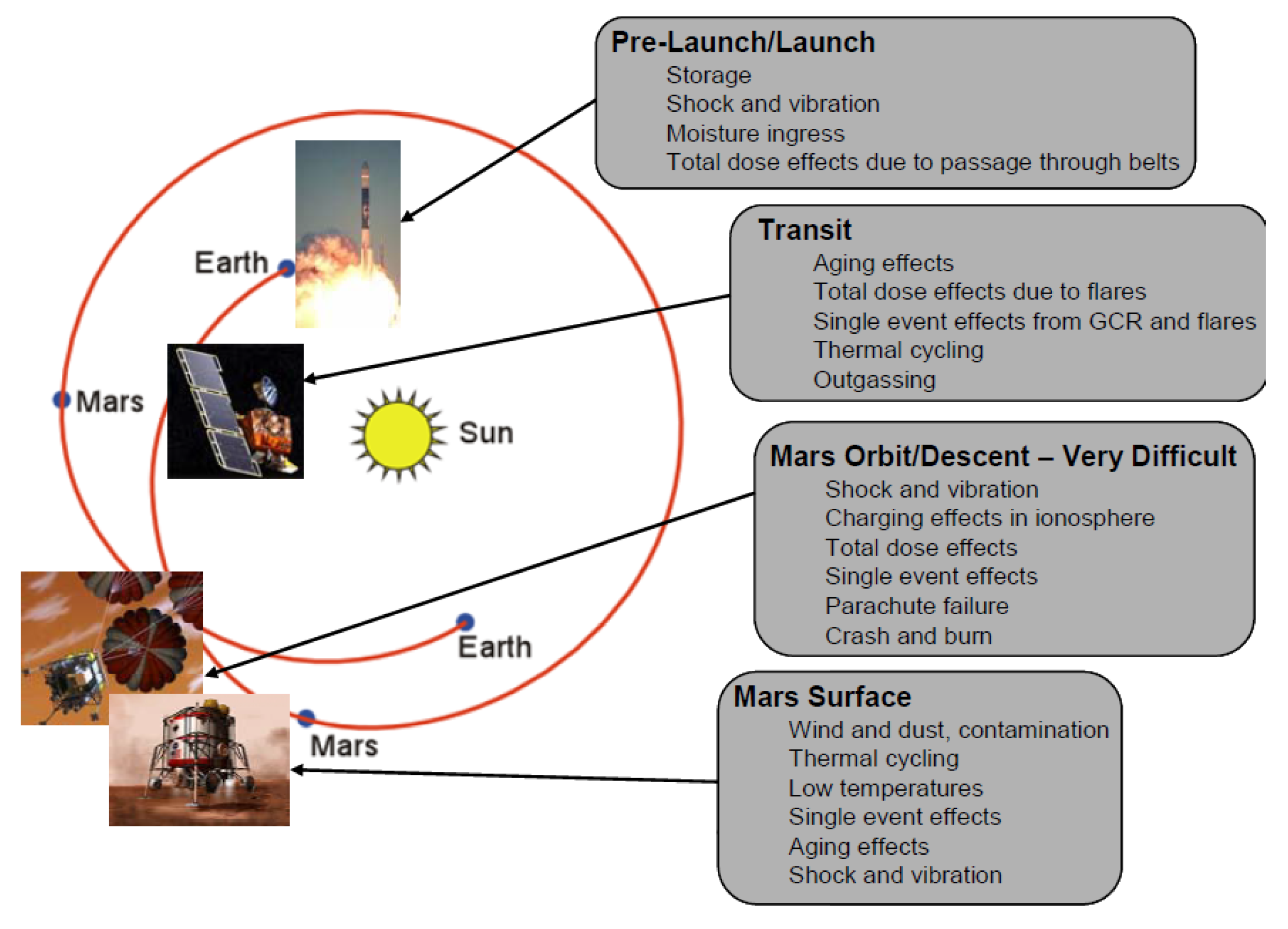
  • usual operation and non-operational temperatures between ≤−45 °C to ≥+85 °C; although those vary depending on the mission space target (Figure 4), or different objects with more or less proximity to the sun [132], tenths of cycles between minimum and maximum limits have to be performed on materials and devices for them to be qualified,
  • harsh vibration (Table 1) and shock (usually 1500 g) resistance, conditions normally due to launch take off and possible planetary landing,
  • vacuum compatibility (10−9 torr),
  • no contamination. Low out-gassing, in terms of total mass loss (TML) and collected volatile condensable materials (CVCM) <0.1%.
Monitoring tests must be performed on individual components and final prototypes before, in some cases during, and after environmental tests in order to detect any deterioration of optical performances that might have occurred. Those tests, aimed at demonstrating that material batches and assembly processes ensure a high repeatably and reliability margin that allows operation in the required mission environments, are expensive and time-consuming. Therefore, most missions tend to use devices as similar as possible to devices that have already been tested, qualified, and, if possible, launched. For instance, the NASA LIDAR missions MOLA, GLAS, CALIOP, MLA, and LOLA all used similar DPSSL configurations, since it worked successfully in the first Martian mission in 1996 [52]. Nevertheless, new developments in the fields of photonic and laser devices provide novel instruments with better performance and new wavelengths that allow for new applications or improved results. The fact that they are not space qualified makes their use risky and they tend to be included only if they really are a game changer key element or are extremely compulsory for the mission purpose.
A considerable amount of work is taking place regarding standardization of the qualification of photonic devices, such as that reported in the following articles: [52] or [132]. Moreover, NASA and the European Cooperation for Space Standardization are working on the development of standards [133,134,135,136] for the manufacture and qualification of photonic and laser devices, helping to disseminate them to the key players and project partners with platforms, such as the one reported in [134].

5. Difficulties, Drawbacks—But Also Final Advantages

Laser devices, photonic devices, and more generally any device launched in space will experience harsh environments during operation, as explained in Section 4. The principal challenge here is to adapt novel sophisticated engineered setups that operate satisfactorily on stable optical tables in controlled laboratory environments into operating devices able to withstand extreme conditions that will eventually misalign or damage the optical components and cause final device failure.
In the specific case of laser diodes, the indium used to package the laser chip could represent a risk in case of extreme temperatures ranges due to the indium creep behaviour that can lead to fatal device failure [135]. Moreover, high vacuum regimes can even cause changes in the chemical and physical properties of components due to dehydration [137]. Another common issue for the laser crystals and fibers is the photodarkening effect produced in optical components due to radiation absorption. Many studies have been performed on the effects of several types of radiation on various laser materials with different doping ratios [138,139], which photonic space engineers should check in order to select the best candidates for their assemblies. This issue can be easily solved by improving the components shielding, however, the increased thickness caused by the extra layers of material protecting the components increases the weight of the integrated device, and frequently its size and cost. For that reason, the components must be carefully selected for optimum match with the mission radiation budgets to ensure that the laser output maintains the required specifications over the long operational period of the mission without incurring in unnecessary cost caused by extra shielding.
Standard assembly techniques used for laser components are also not generally space compatible. For instance, organic epoxies, which are commonly used, cause out-gassing issues, creating laser induced contamination (LIC) and further laser induced damage (LID) [140]. Packaging issues can be solved by using new packaging technologies. Replacing adhesives by techniques, such as low-stress soldering techniques [141], will contribute towards providing more robust DPSSL devices with higher thermal range, higher mechanical strength, lower out-gassing, and improved bonded-materials resistant to radiation.
Some of the advantages offered by new photonic devices over those previously used that make up for the challenge that the environmental tests suppose have been already mentioned in this article [5]:
  • almost limitless bandwidth for lasercom devices,
  • immunity to electromagnetic waves,
  • reliability,
  • efficient and low power consumption,
  • small form factor,
  • low weight.
The final decision to select previously used space-qualified technologies, new photonic qualified devices with high technological readiness level, or completely new and in-development setups will be based on advantages and real needs of the selected option, mission budgets, and possible risks produced by device failure when subjected to space environments. Both reliability and cost factors are important requirements that often greatly affect the design choice, the former also affecting the efficiency trade that needs to be made in terms of de-rating for lifetime.

6. Conclusions

In this review, we have discussed the main types of laser technologies suitable for space applications, with a focus on the laser devices already deployed in space. The main applications were described, together with the most relevant devices deployed during past space missions. These applications include remote sensing (LIDAR), spectroscopy, quantum technologies including atomic clocks and gravitational wave sensors, and communications. Fiber optic sensing, optopyrotechnics, and finally integrated solid state gyroscopes have also been discussed. Future missions and devices have then been mentioned. Finally, technical specifications requirements have been reviewed, before discussing some of the difficulties, drawbacks, and advantages of such devices and technologies.
This review illustrates the general conservative attitude towards the use of laser technologies in space application, since most of the devices currently deployed in space are semiconductor laser diodes or use an Nd:YAG crystal as the active medium. This can be explained by the cost of space missions and by the difficulties for posterior maintenance. These two factors make it more efficient for a new laser device to be based on a validated design from a past mission or to rely on industrial commercial devices, as demonstrated by ESA’s three-fold approach to space qualification of laser devices [5]:
  • assessment of space suitability of commercially available laser products through functional and environmental testing,
  • selection of the most suited component and collaboration with its manufacturer for improvement towards space qualification,
  • formal space qualification of the resulting device.
Nevertheless, novel laser sources and amplifiers (such as EDFA) are appearing in cases where their novelty brings important improvement compared to the state-of-the-art, or when they enable new applications, as is the case with atomic clocks. Such new laser systems are worth the complex, expensive, and time-consuming space qualification process when they provide a high added-value compared to existing space qualified laser technology.

Author Contributions

Conceptualization, D.G. and P.R.-P.; investigation, D.G. and P.R.-P.; data curation, D.G. and P.R.-P.; writing—original draft preparation, D.G. and P.R.-P.; writing—review and editing, D.G. and P.R.-P.; visualization, D.G. and P.R.-P.; supervision, D.G. and P.R.-P.; project administration, D.G. and P.R.-P.

Funding

This research received no external funding.

Acknowledgments

The authors wish to acknowledge Sergi Ferrando i Margalet, Miguel Galan Valiente and Monocrom S.L. in Vilanova I la Geltrù, as well as the Lotus and Ester Sánchez Ràfols who have, in different ways, initiated and strengthened this collaboration. Also, Robert Eckardt for Figure 1 and others published elsewhere, and finally some colleagues who helped us improve this review: Fabian Oliver Steinlechner, Lilia Espada, Aoife Brady, Andrej Krzic, and Gonzalo Palma Vega. Finally, to George Lucas and Star Wars.

Conflicts of Interest

The authors declare no conflict of interest.

References

  1. CubeSats: Tiny, Versatile Spacecraft Explained. Available online: https://www.space.com/29320-cubesats-spacecraft-tech-explained-infographic.html (accessed on 4 June 2019).
  2. CubeSats: Tiny Payloads, Huge Benefits for Space Research. Available online: https://www.space.com/34324-cubesats.html (accessed on 4 June 2019).
  3. A Basic Guide to Nanosatellites. Available online: https://alen.space/basic-guide-nanosatellites/ (accessed on 4 June 2019).
  4. Britain Competes for the Launch of an Estimated 2000 Satellites by 2030. Available online: https://www.gov.uk/government/news/britain-competes-for-the-launch-of-an-estimated-2000-satellites-by-2030 (accessed on 4 June 2019).
  5. Karafolas, N.; Armengol, J.M.P.; Mckenzie, I. Introducing photonics in spacecraft engineering: ESA’s strategic approach. In Proceedings of the 2009 IEEE Aerospace Conference, Big Sky, MT, USA, 7–14 March 2009. [Google Scholar]
  6. Smullin, L.D.; Fiocco, G. Optical echoes from the moon. Nature 1962, 194, 1267. [Google Scholar] [CrossRef]
  7. Yu, A.W.; Li, S.X.; Shaw, G.B.; Seas, A.; Stephen, M.A.; Troupaki, E.; Vasilyev, A.; Ramos-Izquierdo, L.; Lukemier, A.; Mamakos, W.; et al. Overview of Space Qualified Solid-State Lasers Development at NASA Goddard Space Flight Center. In Proceedings of the SPIE LASE: Lasers and Applications in Science and Engineering, San Jose, CA, USA, 13 February 2009; Volume 7193. [Google Scholar]
  8. Zuber, M.T.; Smith, D.E.; Solomon, S.C.; Muhleman, D.O.; Head, J.W.; Garvin, J.B.; Abshire, J.B.; Bufton, J.L. The Mars Observer Laser Altimeter Investigation. J. Geophys. Res. 1992, 97, 7781–7797. [Google Scholar] [CrossRef]
  9. A World First: Data Transmission between European Satellites Using Laser Light. Available online: https://www.esa.int/Our_Activities/Telecommunications_Integrated_Applications/A_world_first_Data_transmission_between_European_satellites_using_laser_light (accessed on 4 June 2019).
  10. War of the Worlds: Curiosity Fires First Laser Shot on Mars. Available online: https://newatlas.com/curiosity-laser-firing/23761/ (accessed on 4 June 2019).
  11. Mondin, L. Laser Diodes in Space: Needs Expression. CNES Laser Diodes in Space Workshop. 2006. Available online: https://escies.org/download/webDocumentFile?id=2208 (accessed on 5 July 2019).
  12. Cousin, A.; Maurice, S.; Parot, Y.; Michel, Y.; Le Roch, N.; Dalmau, J.; Pares, L.; Perez, R.; Cros, A.; Wiens, R. ChemCam (MSL) Autofocus Capabilities. In Proceedings of the 40th Lunar and Planetary Science Conference, Woodlands, TX, USA, 23–27 March 2009; p. 1684. [Google Scholar]
  13. Minec-Dube, S. Evaluation and Space Qualification of laser diodes for ATV-videometer and PHARAO projects. Workshop Laser Diodes in Space. 2006. Available online: https://escies.org/webdocument/showArticle?id=683&groupid=6 (accessed on 5 July 2019).
  14. Carson, R.F.; Taylor, E.W.; Paxton, A.H.; Schone, H.; Choquette, K.D.; Hou, H.Q.; Warren, M.E.; Lear, K.L. Surface-emitting laser technology and its application to the space radiation environment. In Proceedings of the SPIE OPTO, San Diego, CA, USA, 29 July 1997; p. 10288. [Google Scholar]
  15. LaForge, L.E.; Moreland, J.R.; Bryan, R.G.; Fadali, M.S. Vertical Cavity Surface Emitting Lasers for Spaceflight Multi-Processors. In Proceedings of the IEEE Aerospace Conference, Big Sky, MT, USA, 4–11 March 2006; Volume 1355. [Google Scholar]
  16. Ellmeier, M.; Hagen, C.; Piris, J.; Lammegger, R.; Jernej, I.; Woschank, M.; Magnes, W.; Murphy, E.; Pollinger, A.; Erd, C.; et al. Accelerated endurance test of single-mode vertical-cavity surface-emitting lasers under vacuum used for a scalar space magnetometer. Appl. Phys. B 2018, 124, 18. [Google Scholar] [CrossRef] [Green Version]
  17. Chaudron, S.; Gernigon, V.; Rissons, A. Vertical-cavity surface-emitting laser characterizations for space applications. In Proceedings of the SPIE OPTO, San Francisco, CA, USA, 4 March 2015; Volume 9381. [Google Scholar]
  18. Coyle, D.B.; Stysley, P.R. The High Output Maximum Efficiency Resonator (HOMER) Developed for Long Life, Space-Based Altimetry. In Proceedings of the IEEE Aerospace Conference, Big Sky, MT, USA, 4–11 March 2006. [Google Scholar]
  19. Ribes-Pleguezuelo, P.; Moral, A.; Basset, M.G.; Rodriguez, P.; Rodriguez, G.; Laudisio, M.; Galan, M.; Hornaff, M.; Beckert, E.; Eberhardt, R.; et al. Assembly process comparison for a miniaturized laser used for the Exomars European Space Agency mission. Opt. Eng. 2016, 55, 116107. [Google Scholar] [CrossRef]
  20. Coyle, D.B. Applications of Fiber Amplifiers for Space: Laser Altimetry and Mapping. The First ESA-NASA Working Meeting on Optoelectronics: Fiber Optic System Technologies in Space. 2005. Available online: https://escies.org/download/webDocumentFile?id=1609 (accessed on 8 July 2019).
  21. Haddad, E.; Kruselecky, R.V.; Mena, M.; Tagziria, K.; Ricci, F.; McKenzie, I.; Karafolas, N.; Hannoteau, F. Optical Fiber sensors system on Proba-2 after 7 years. In Proceedings of the ICSO 2016 International Conference on Space Optics, Biarritz, France, 18–21 October 2016. [Google Scholar]
  22. Rogers, M.E. Lasers in Space–Technological Options for Enhancing US Military Capabilities; Occasional Paper No.2; Center for Strategy and Technology, Air War College: Montgomery, AL, USA, 1997. [Google Scholar]
  23. Lingvay, L.S.; Bowman, A.P.; Wallace, A.S. Laser Payloads on Small Satellites; White Paper; Space Applications Corp: Arlington, VA, USA, 1990. [Google Scholar]
  24. Young, C.G. A sun-pumped cw one-watt laser. Appl. Opt. 1966, 5, 993–997. [Google Scholar] [CrossRef] [PubMed]
  25. Eubanks, P.; Marzocca, P.; Payziyev, S.; Radley, C. Solar Pumped Lasers to Directly Convert Sunlight to Laser Radiation; White Paper: Information Program NNH15ZOA001L; Leeward Space Foundation: Americus, GA, USA, 2015. [Google Scholar]
  26. Wittrock, U. Perspective of Solar pumping of Solid State Lasers for ESA missions. Contract Number 400106760. 2013. Available online: https://nebula.esa.int/content/perspective-solar-pumping-solid-state-lasers-esa-missions (accessed on 8 July 2019).
  27. Adsys Controls, Inc. Laser Application for Space Navigation. Available online: https://www.nasa.gov/sites/default/files/atoms/files/05_adsys_controls_laser_application_for_space_navigation.pdf (accessed on 27 March 2019).
  28. NASA- LAser GEOdynamic Satellite (LAGEOS). Available online: https://lageos.cddis.eosdis.nasa.gov/ (accessed on 8 March 2019).
  29. Lidar In-Space Technology Experiment. Available online: https://www-lite.larc.nasa.gov/ (accessed on 18 June 2019).
  30. Chen, W. Spaceborne Laser Technology for Lidar Remote Sensing. Light: A Bridge between Earth and Space: Winter College on Optics. 2015. Available online: http://indico.ictp.it/event/a14287/session/6/contribution/21/material/slides/0.pdf (accessed on 8 June 2019).
  31. Bufton, J.L.; Harding, D.J.; Garvin, J.B. Shuttle Laser Altimeter Mission Results and Pathfinder Accomplishments. NASA, 1999. Available online: https://pdfs.semanticscholar.org/5618/67f6271d662da728e60031a8567c3cce4947.pdf?_ga=2.81158608.696812552.1560850487-1171316160.1557831070 (accessed on 30 July 2019).
  32. ESA- Rain Forest Observation. Available online: https://www.esa.int/Our_Activities/Observing_the_Earth/Earth_from_Space_Rainforest_river (accessed on 8 March 2019).
  33. The Envisat Satellite and Its Integration. Available online: https://www.esa.int/esapub/bulletin/bullet106/bul106_2.pdf (accessed on 2 April 2019).
  34. Afzal, S.R.; Yu, A.W.; Dallas, J.L.; Melak, A.; Lukemire, A.T.; Ramos-Izquierdo, L.; Mamakos, W. The Geoscience Laser Altimeter System (GLAS) Laser Transmitter. IEEE J. Sel. Top. Quantum Electron. 2007, 13, 511–536. [Google Scholar] [CrossRef] [Green Version]
  35. Patil, D.S. Semiconductor Laser Diode: Technology and Applications; InTech: Rijeka, Croatia, 2012; p. 223. ISBN 978-953-51-0549-7. [Google Scholar]
  36. Sun, X.; Abshire, J.B.; Krainak, M.A.; Spinhime, J.D.; Palm, S.S.; Lancaster, R.S.; Allan, G.R. Cloud and aerosol lidar channel design and performance of the Geoscience Laser Altimeter System on the ICESat mission. In Proceedings of the Conference on Lasers and Electro-Optics (CLEO), San Francisco, CA, USA, 16–21 May 2004. [Google Scholar]
  37. The Cloud-Aerosol Lidar and Infrared Pathfinder Satellite Observation (CALIPSO). Available online: https://www-calipso.larc.nasa.gov/ (accessed on 18 June 2019).
  38. CALIPSO PAYLOAD. Available online: https://www-calipso.larc.nasa.gov/about/payload.php (accessed on 18 June 2019).
  39. ESA- Sentinel-1. Available online: https://www.esa.int/Our_Activities/Observing_the_Earth/Copernicus/Sentinel-1/Satellites_shed_new_light_on_earthquakes (accessed on 8 March 2019).
  40. Storm, M.; Stevenson, G.; Hovis, F.; Gavert, W.; Dang, X.; Darab, A.; Chuang, T.; Burns, P. LIDAR and LASER technology for NASA’s Cloud-Aerosol Transport System (CATS) payload on the International Space Station (JEM-EF). ILRC 27 2016, 119, 04002. [Google Scholar] [CrossRef]
  41. Hovis, F. Recent Progress on Lasers for Space-Based Wind, Aerosol, and Altimetry Lidar Systems. LWG Meeting. 2014. Available online: http://cires1.colorado.edu/events/lidarworkshop/LWG/May14/ presentations/Fibertek%20LWG%20Boulder%202014v4.pdf (accessed on 8 July 2019).
  42. ESA-Aelus. Available online: https://www.esa.int/Our_Activities/Observing_the_Earth/Aeolus/Aeolus_laser_shines_light_on_wind (accessed on 12 March 2019).
  43. NASA- ICESat-2. Available online: https://directory.eoportal.org/web/eoportal/satellite-missions/i/icesat-2 (accessed on 2 April 2019).
  44. NASA- EUMETSAT. Available online: https://gracefo.jpl.nasa.gov/mission/overview/ (accessed on 8 April 2019).
  45. NASA- Lasers in Space: Earth Mission Tests New Technology. Available online: https://www.nasa.gov/feature/jpl/lasers-in-space-earth-mission-tests-new-technology (accessed on 7 April 2019).
  46. ISS Utilization: GEDI (Global Ecosystems Dynamics Investigation Lidar). Available online: https://directory.eoportal.org/web/eoportal/satellite-missions/content/-/article/iss-gedi (accessed on 20 June 2019).
  47. Shannon, M.J. The Clementine Satellite. In ET and TR; 1994. Available online: https://str.llnl.gov/etr/pdfs/06_94.1.pdf (accessed on 4 July 2019).
  48. SELENE. Available online: https://earth.esa.int/web/eoportal/satellite-missions/s/selene (accessed on 19 June 2019).
  49. Chang’e - 1 (Lunar-1 Mission of China). Available online: https://directory.eoportal.org/web/eoportal/satellite-missions/c-missions/chang-e-1 (accessed on 19 June 2019).
  50. China to launch Chan’E 2 on Friday, October 1. Available online: http://www.planetary.org/blogs/emily-lakdawalla/2010/2684.html (accessed on 20 June 2019).
  51. Smith, D.E.; Zueber, M.T.; Jackson, G.B.; Cavanauch, J.F.; Neumann, G.A.; Riris, H.; Sun, X.; Zellar, R.S.; Coltharp, C.; Connelly, J.; et al. The Lunar Orbiter Laser Altimeter Investigation on the Lunar Reconnaissance Orbiter Mission. Space Sci. Rev. 2010, 150, 209–241. [Google Scholar] [CrossRef]
  52. Troupaki, E.; Stephen, M.A.; Vasilyev, A.A.; Yu, A. Laser Diode Pump Technology for Space Applications, Semiconductor Laser Diode Technology and Applications; Patil, D.S., Ed.; InTech: London, UK, 2012; pp. 219–240. ISBN 978-953-51-0549-7. [Google Scholar]
  53. Afzal, R.S. Mars Observer Laser Altimeter: Laser transmitter. Appl. Opt. 1994, 33, 3184–3188. [Google Scholar] [CrossRef]
  54. Whiteway, J.; Daly, M.; Carswell, A.; Duck, T.; Dickinson, C.; Komguem, L.; Cook, C. Lidar on the Phoenix mission to Mars. J. Geophys. Res. Planets 2008, 113, E3. [Google Scholar] [CrossRef]
  55. Cavanaugh, J.F.; Smith, J.C.; Sun, X.; Bartels, A.E.; Ramos-Izquierdo, L.; Krebs, J.D.; McGarry, J.F.; Trunzo, R.; Novo-Gradac, A.M.; Britt, J.L.; et al. The Mercury Laser Altimeter Instrument for the MESSENGER Mission. Space Sci. Rev. 2007, 131, 451–479. [Google Scholar] [CrossRef] [Green Version]
  56. Kallenbach, R.; Murphy, E.; Gramkow, B.; Rech, M.; Weidlich, K.; Leikert, T.; Henkelmann, R.; Trefzger, B.; Metz, B.; Michaelis, H.; et al. Space-qualified laser system for the BepiColombo Laser Altimeter. Appl. Opt. 2013, 52, 8732–8746. [Google Scholar] [CrossRef] [PubMed] [Green Version]
  57. Zuber, M.T.; Smith, D.E.; Cheng, A.F.; Cole, T.D. The NEAR laser ranging investigation. J. Geophys. Res. 1997, 102, 23761–23773. [Google Scholar] [CrossRef]
  58. Mizuno, T.; Tsuno, K.; Okumura, E.; Nakayama, M. Evaluation of LIDAR System in Rendezvous and Touchdown Sequence of HAYABUSA mission. Trans. Japan Soc. Aero. Space Sci. 2010, 53, 47–53. [Google Scholar] [CrossRef]
  59. Namiki, N.; Mizuno, T.; Senshu, H.; Yamada, R.; Noda, H.; Shizugami, M.; Hirata, N.; Ikeda, H.; Abe, S.; Matsumoto, K.; et al. Performance of Hayabusa-2 Lidar in acceptance and verification tests. In Proceedings of the 46th Lunar and Planetary Science Conference, The Woodlands, TX, USA, 16–20 March 2015; p. 1798. [Google Scholar]
  60. Neumann, G.A.; Barker, M.K.; Mazarico, E.; Barnouin, O.S.; Daly, M.G.; Lauretta, D.S. OSIRIS-REx Laser altimeter 1064-nm reflectance investigation at Bennu. In Proceedings of the 49th Lunar and Planetary Science Conference, The Woodlands, TX, USA, 19–23 March 2018; p. 1676. [Google Scholar]
  61. Hussmann, H.; Lingenauber, K.; Kallenbach, R.; Oberst, J.; Enya, K.; Kobayashi, M.; Namiki, N.; Kimura, J.; Thomas, N.; Lara, L.; et al. The Ganymede Laser Altimeter (GALA). Epsc Abstr. 2014, 9, EPSC2014-347. [Google Scholar]
  62. Edwin Hubble and the Expanding Universe. Available online: https://www.atnf.csiro.au/outreach/education/senior/cosmicengine/hubble.html (accessed on 21 June 2019).
  63. Ciminelli, C.; Del’Olio, F.; Armensie, M.N. Photonic Sensors and Instruments. In Photoncis in Space, Advanced Photonic Devices and Systems; World Scientific: London, UK, 2016; pp. 180–185. ISBN 9789814725101. [Google Scholar]
  64. Wiens, R.C.; Sylvestre, R.C.; Perez, F.R. The SuperCAM remote sensing instrument suite for the Mars 2020 rover mission: A preview. Spectroscopy 2017, 32, 50–55. [Google Scholar]
  65. Beegle, L.; Bhartia, R.; White, M.; DeFlores, L.; Abbey, W.; Wu, Y.H.; Cameron, B.; Moore, J.; Fries, M.; Burton, A.; et al. Sherlock: Scanning habitable environments with Raman and luminescence for organics and chemicals. In Proceedings of the IEEE Aerospace Conference, Big Sky, MT, USA, 7–14 March 2015; pp. 1–11. [Google Scholar]
  66. Solanki, R.; Fairbank, W.M.; Collins, G.J. Multiwatt Operation of Cu II and Ag II Cathode Lasers. IEEE J. Quantum Electron. 1980, QE-16, 1292–1294. [Google Scholar] [CrossRef]
  67. Photonsystems-Space Qualified Deep UV. Available online: https://photonsystems.com/space-qualified/ (accessed on 28 February 2019).
  68. Vago, J.L.; Westall, F.; Coates, A.J.; Jaumann, R.; Korablev, O.; Ciarletti, V.; Mitrifanov, I.; Josset, J.L.; DeSanctis, M.C.; Bibring, J.P.; et al. Habitability on Early Mars and the Search for Biosignatures with the ExoMars Rover. Astrobiology 2017, 17. [Google Scholar] [CrossRef]
  69. Goesmann, F.; Brinckerhoff, W.B.; Raulin, F.; Goetz, W.; Danell, R.M.; Getty, S.A.; Siljestrom, S.; Missbach, H.; Steininger, H.; Arevalo, R.D.; et al. The Mars Organic Molecule Analyzer (MOMA) Instrument: Characterization of Organic Material in martian Sediments. Astrobiology 2017, 17, 655–685. [Google Scholar] [CrossRef]
  70. Kolleck, C.; Buttner, A.; Ernst, M.; Hulsenbusch, T.; Lang, T.; Marwah, R.; Mebben, S.; Priehs, M.; Kracht, D.K.; Neumann, J. Development of a pulsed UV laser system for laser-desorption mass spectrometry on Mars. In Proceedings of the International Conference on Space Optics (ICSO), Rhodes Island, Greece, 20 November 2010; Volume 10. [Google Scholar]
  71. Ribes-Pleguezuelo, P.; Guilhot, D.; Gilaberte Basset, M.; Beckert, E.; Eberhardt, R.; Tünnermann, A. Insights of the Qualified ExoMars Laser and Mechanical Considerations of Its Assembly Process. Instruments 2019, 3, 25. [Google Scholar] [CrossRef]
  72. Laxmiprasad, A.S.; Sridhar Raja, V.L.N.; Goswami, A.; Menon, S.; Rao, M.V.H.; Lohar, K.A. Laser Induced Breakdown Spectrometer (LIBS) for Chandrayaan-2 Rover. Planex 2011, 1, 16–18. [Google Scholar]
  73. Webster, C.R.; Christensen, L.E.; Flesch, J.G.; Forouhar, S.; Briggs, R.; Keymeulen, D.; Blacksberg, J.; Mahaffy, P.R. Tunable Laser Spectrometers for Space Science. In Proceedings of the International Workshop on Instrumentation for Planetary Missions (IPM-2014), Greenbelt, Maryland, 4–7 November 2014. [Google Scholar]
  74. Nurul Abedin, M.; Bradley, A.T.; Misra, A.K.; Bai, Y.; Hines, G.D.; Sharma, S.K. Standoff ultracompact micro-Raman sensor for planetary surface explorations. Appl. Opt. 2018, 57, 62–68. [Google Scholar] [CrossRef] [PubMed]
  75. Schuldt, T.; Schuber, C.; Krutzik, M.; Bote, L.G.; Gaaloul, N.; Hartwig, J.; Ahlers, H.; Herr, W.; Posso-Trujillo, K.; Rudolph, J.; et al. Design of a dual species atom interferometer for space. Experimental Astronomy 2015, 39, 167–206. [Google Scholar] [CrossRef]
  76. ESA STE-QUEST. Available online: http://sci.esa.int/ste-quest/ (accessed on 28 March 2019).
  77. Schkolnik, V.; Hellmig, O.; Wenzlawski, A.; Grosse, J.; Kohfeldt, A.; Doringshoff, K.; Wicht, A.; Windpassinger, P.; Sengstock, K.; Braxmaier, C.; et al. A compact and robust diode laser system for atom interferometry on a sounding rocket. Appl. Phys. B 2016, 122, 217. [Google Scholar] [CrossRef]
  78. Luvsandamdin, E.; Kurbis, C.; Schiemangk, M.; Sahm, A.; Wicht, A.; Peters, A.; Erbert, G.; Trankle, G. Micro-integrated extended cavity diode lasers for precision potassium spectroscopy in space. Opt. Express 2014, 22, 7790–7798. [Google Scholar] [CrossRef] [PubMed]
  79. Gilowski, M.; Schubert, C.; Zaiser, M.; Herr, W.; Wubbena, T.; Wendrich, T.; Muller, T.; Rasel, E.M.; Ertmer, W. Narrow bandwidth interference filter stabilized diode laser systems for the manipulation of neutral atoms. Opt. Commun. 2007, 280, 443–447. [Google Scholar] [CrossRef]
  80. Liu, L.; Lu, D.S.; Chen, W.B.; Li, T.; Qu, Q.Z.; Wang, B.; Li, L.; Ren, W.; Dong, Z.R.; Zhao, J.B.; et al. In-orbit operation of an atomic clock based on laser-cooled 87Rb atoms. Nat. Commun. 2018, 9, 2760. [Google Scholar] [CrossRef] [PubMed]
  81. Elliott, E.R.; Krutzik, M.C.; Williams, J.R.; Thompson, R.J.; Aveline, D.C. NASA’s Cold Atom Lab (CAL): System development and ground test status. NPJ Microgravity 2018, 4, 16. [Google Scholar] [CrossRef]
  82. ISS Utilization: ACES (Atomic Clock Ensemble in Space)/PHARAO. Available online: https://directory.eoportal.org/web/eoportal/satellite-missions/i/iss-aces-pharao (accessed on 3 July 2019).
  83. Schiller, S. Mission I-SOC: An Optical Clock on the ISS. COST Action QTSpace. 2017. Available online: http://www.qtspace.eu/sites/testqtspace.eu/files/presentations/Schiller%20-%20ISOC%20an% 20optical%20clock%20on%20the%20ISS%20-%20Malta%20COST%202017.pdf (accessed on 8 July 2019).
  84. McNamara, P. LISA Pathfinder: First steps to observing gravitational waves from space. J. Phys. Conf. Ser. 2017, 840. [Google Scholar] [CrossRef]
  85. Karafolas, N.; Sodnik, Z.; Armengol, J.M.P.; McKenzie, I. Optical communications in space. In Proceedings of the International Conference on Optical Network Design and Modeling, Braunschweig (Brunswick), Germany, 18–20 February 2009. [Google Scholar]
  86. Iida, T.; Pelton, J.N.; Ashford, E. Progress in Astronautics and Aeronautics: Satellite Communications In the 21st Century: Trends and Technologies; American Institute of Aeronautics and Astronautics: Reston, VA, USA, 2003; ISBN 978-1-60086-669-2. [Google Scholar]
  87. Hemmati, H. Deep Space Optical Communications; John Wiley & Sons: Hoboken, NJ, USA, 2005; Available online: http://media.taricorp.net/spdf/DeepSpaceOpticalCommunicatio-HamidHemmati.pdf (accessed on 30 July 2019).
  88. Cornwell, D.M. NASA’s Optical Communications Program for 2015 and Beyond. SPIE LASE 2015, 93540E. [Google Scholar] [CrossRef]
  89. Lunar Laser Communication Demonstration. Available online: http://spaceflight101.com/ladee/lunar-laser-communication-demonstration/ (accessed on 9 July 2019).
  90. China Communication Satellite Tests. Available online: http://en.hit.edu.cn/news/3066 (accessed on 13 March 2019).
  91. NASA- LCRD: 2019. Available online: https://www.nasa.gov/directorates/heo/scan/opticalcommunications/lcrd (accessed on 29 August 2019).
  92. eoPortal- LCRD (Laser Communications Relay Demonstration) Mission. Available online: https://eoportal.org/web/eoportal/satellite-missions/content/-/article/lcrd (accessed on 29 August 2019).
  93. Edwards, B.L.; Israel, D.; Wilson, K.; Moores, J.; Fletcher, A. Overview of the Laser Communications Relay Demonstration Project. In Proceedings of the SpaceOps 2012 Conference, Stockholm, Sweden, 11–15 June 2012. [Google Scholar]
  94. SAMPEX (Solar Anomalous and Magnetospheric Particle Explorer). Available online: https://directory.eoportal.org/web/eoportal/satellite-missions/s/sampex (accessed on 15 March 2019).
  95. Marshall, P.W.; Dale, C.J.; LaBel, K.A. Space radiation effects in high performance fiber optic data links for satellite data management. IEEE Trans. Nucl. Sci. 1996, 43, 645–653. [Google Scholar] [CrossRef]
  96. SMOS (Soil Moisture and Ocean Salinity) Mission. Available online: https://directory.eoportal.org/web/eoportal/satellite-missions/content/-/article/smos (accessed on 14 March 2019).
  97. Palacio, R.; Deborgies, F.; Piironen, P. Optical distribution of microwave signals for Earth Observation satellites. In Proceedings of the IEEE International Topical Meeting on Microwave Photonics, Montreal, QC, Canada, 5–9 October 2010. [Google Scholar]
  98. Arruego, I.; Guerrero, H.; Rodriguez, S.; Martinez-Oter, J.; Jimenez, J.J.; Domingez, J.A.; Martin-Ortega, A.; DeMingo, J.R.; Rivas, J.; Apestigue, V.; et al. OWLS: A Ten-Year History in Optical Wireless Links for Intra-Satellite Communications. IEEE J. Sel. Areas Commun. 2009, 27, 1599–1611. [Google Scholar] [CrossRef]
  99. Tolker-Nielsen, T.; Oppenhauser, G. In-orbit test result of an operational optical intersatellite link between ARTEMIS and SPOT4, SILEX. In Proceedings of the SPIE, Free-Space Laser Communication Technologies XIV, San Jose, CA, USA, 26 April 2002; Volume 4635. [Google Scholar]
  100. Tolker-Nielsen, T. Pointing, acquisition, and tracking system for the free-space laser communication system SILEX. In Proceedings of the SPIE, Free-Space Laser Communication Technologies VII, San Jose, CA, USA, 20 April 1995; Volume 2381. [Google Scholar]
  101. Heine, F.; Kämpfner, H.; Czichy, R.; Meyer, R.; Lutzer, M. Optical inter-satellite communication operational. In Proceedings of the IEEE Milcom 2010 Military Communications Conference, San Jose, CA, USA, 31 October–3 November 2010. [Google Scholar]
  102. NASA-NFIRE Mission Information. Available online: https://www.nasa.gov/centers/wallops/missions/nfire.html (accessed on 29 August 2019).
  103. Sotnik, Z.; Sans, M. Extending EDRS to Laser Communication from Space to Ground. In Proceedings of the International Conference on Space Optical Systems and Applications (ICSOS), Ajaccio, Corsica, France, 14–16 November 2012. [Google Scholar]
  104. Benzi, E.; Shurmer, I.; Policella, N.; Troendle, D.; Lutzer, M.; Kuhlmann, S.; James, M. Optical Inter-Satellite Communication: The Alphasat and Sentinel-1A in-orbit experience. In Proceedings of the SpaceOps 2016 Conference, Daejeon, Korea, 16–20 May 2016; Volume 14, p. 2389. [Google Scholar] [CrossRef]
  105. TESAT. Available online: https://www.tesat.de/en/10 (accessed on 13 March 2019).
  106. Liao, S.K.; Cai, W.Q.; Handsteiner, J.; Liu, B.; Yin, J.; Zhang, L.; Rauch, D.; Fink, M.; Ren, J.G.; Liu, W.Y.; et al. Satellite-Relayed Intercontinental Quantum Network. Phys. Rev. Lett. 2018, 120, 030501. [Google Scholar] [CrossRef] [PubMed] [Green Version]
  107. Yin, J.; Cao, Y.; Li, Y.H.; Liao, S.K.; Zhang, L.; Ren, J.G.; Cai, W.Q.; Liu, W.Y.; Li, B.; Dai, H.; et al. Satellite-based entanglement distribution over 1200 kilometers. Science 2017, 356, 1140–1144. [Google Scholar] [CrossRef] [PubMed] [Green Version]
  108. Calderaro, L.; Agnesi, C.; Dequal, D.; Vedovato, F.; Schiavon, M.; Santamato, A.; Luceri, V.; Bianco, G.; Vallone, G.; Villoresi, P. Towards quantum communication from global navigation satellite system. Quantum Sci. Technol. 2018, 4, 015012. [Google Scholar] [CrossRef] [Green Version]
  109. Haber, R.; Garbe, D.; Schilling, K.; Rosenfeld, W. QUBE-A CubeSat for Quantum Key Distribution Experiments. In Proceedings of the AIAA/USU Conference on Small Satellites CSS18, Logan, UT, USA, 4–9 August 2018; Volume 3. [Google Scholar]
  110. SpooQy-1: The Quantum Nanosatellite. Available online: https://sites.google.com/site/phylej/projects-1/spooqy-1 (accessed on 25 July 2019).
  111. Takenaka, H.; Carrasco-Casado, A.; Fujiwara, M.; Kitamura, M.; Sasaki, M.; Toyoshima, M. Satellite-to-ground quantum-limited communication using a 50-kg-class microsatellite. Nat. Photonics 2017, 11, 502–508. [Google Scholar] [CrossRef] [Green Version]
  112. Philipp Neumann, S.; Koduru Joshi, S.; Fink, M.; Scheidl, T.; Blach, R.; Scharlemann, C.; Abouagaga, S.; Bambery, D.; Kerstel, E.; Barthelemy, M.; et al. Q3Sat: Quantum communications uplink to a 3U CubeSat—feasibility and design. EPJ Quantum Technol. 2018, 5, 107990D. [Google Scholar] [CrossRef]
  113. Beckert, E.; DeVires, O.; Ursin, R.; Steinlechner, F.O.; Gräfe, M.; Basset, M.G. A space-suitable, high brilliant entangled photon source for satellite based quantum key distribution. In Proceedings of the Free-Space Laser Communications XXXI, San Francisco, CA, USA, 4 March 2019; Volume 10910. [Google Scholar]
  114. Sodnik, Z.; Perdigues-Armengol, J.; Czichy, R.H.; Meyer, R. Adaptive optics and ESA’s optical ground station. In Proceedings of the SPIE, Free-Space Laser Communication Technologies IX, San Diego, CA, USA, 21 August 2009; Volume 7464. [Google Scholar]
  115. Marinan, A.; Cahoy, K.L.; Merck, J.; Belikov, R.; Bendek, E. Improving Nanosatellite Imaging with Adaptive Optics. In Proceedings of the Small Satellite Conference, Logan, UT, USA, 8–13 August 2016. [Google Scholar]
  116. Pugh, C.J.; Lavigne, J.F.; Bourgoin, J.P.; Higgins, B.L.; Jennewein, T. Adaptive optics benefit for quantum key distribution uplink from ground to a satellite. arXiv 2019, References for Fiber Optic Sensing Reference FSDG1. arXiv:1906.04193. [Google Scholar]
  117. McKenzie, I.; Karafols, N. Fiber Optic Sensing in Space Structures: The Experience of the European Space Agency. In Proceedings of the SPIE 17th International Conference on Optical Fibre Sensors, Bruges, Belgium, 23 May 2005; Volume 5855. [Google Scholar]
  118. Abad, S.; Araujo, F.; Pinto, F.; González Torres, J.; Rodriguez, R.; Moreno, M.A. Fiber Optic Sensing Subsystem for Temperature Monitoring in Space In-flight Applications. In Proceedings of the ICSO 2014, Tenerife, Spain, 7–10 October 2014. [Google Scholar]
  119. Ibrahim, S.K.; Honniball, A.; McCue, R.; Todd, M.; O’Dowd, J.A.; Sheils, D.; Voudouris, L.; Farnan, M.; Hurni, A.; Putzer, P.; et al. Design Challenges of a Tunable Laser Interrogator for Geo-Stationary Communication Satellites. In Proceedings of the ICSO 2016, Biarritz, France, 21 October 2016; Volume 153. [Google Scholar]
  120. Kher, S.; Saxena, M.K. Distributed, Advanced Fiber Optic Sensors. In Applications of Optical Fibers for Sensing; IntechOpen: London, UK, 2018. [Google Scholar]
  121. Fidelus, J.D.; Wysokiński, K.; Stańczyk, T.; Kołakowska, A.; Nasiłowski, P.; Lipiński, S.; Tenderenda, T.; Nasiłowski, T. Metal-coated optical fibers for high temperature sensing applications. In Proceedings of the Remote Sensing Technologies and Applications in Urban Environments II, Warsaw, Poland, 4 October 2017; Volume 10431. [Google Scholar]
  122. Lien, Y.; Thoen, G.; Grasvik, J.; Bru, J.; Paulsen, K.; Lierstuen, L.O.; Chamayou, B.; Pinard, D. Opto-pyrotechnics for space applications. ICSO 2010, 10565. [Google Scholar] [CrossRef]
  123. Manfletti, C.; Kroupa, G. Laser ignition of a cryogenic thruster using a miniaturised Nd:YAG laser Optics Express. Optics. Express 2013, 21, A1126–A113. [Google Scholar] [CrossRef]
  124. Ribes-Pleguezuelo, P.; Beckert, E.; Damm, C.; Bodemann, A.; Eberhardt, R.; Tünermann, A.; Pavel, N.; Grigore, O.A.; Croitoru, G.; Brandus, C.A.; et al. The “Golden” Laser Spark Plug Assembly Process. In Proceedings of the Laser Ignition Conference, Yokohama, Japan, 22–26 April 2019; Volume 7. [Google Scholar]
  125. Soller, S.; Rackermann, N.; Kroupa, G. Laser Ignition Application to Cryogenic Propellant Rocket Thrust Chambers. In Proceedings of the Laser Ignition Conference 2017, OSA Technical Digest (online) (Optical Society of America, 2017), Bucharest, Romania, 20–23 June 2017; Volume LFA4.3. [Google Scholar]
  126. Soller, S.; Rackermann, N.; Preuss, A.; Kroupa, G. Application of laser-ignition systems in liquid rocket engines. In Proceedings of the Space Propulsion Conference 2016, Roma, Italy, 2–6 May 2016; Volume 3124877. [Google Scholar]
  127. Dell’Olio, F.; Tatoli, T.; Ciminelli, C.; Armenise, M.N. Recent advances in miniaturized optical gyroscopes. JEOS 2014, 9. [Google Scholar] [CrossRef] [Green Version]
  128. Unger, G.L.; Kaufman, D.M.; Krainak, M.A.; Sanders, G.A.; Taylor, W.L.; Schulze, N.R. NASA’s first in-space optical gyroscope: A technology experiment on the X-ray Timing Explorer spacecraft. In Proceedings of the Photonics for Space Environments, Orlando, FL, USA, 15 September 1993. [Google Scholar]
  129. Buret, T.; Ramecourt, D.; Napolitano, F. From space qualified fiber optic gyroscope To generic fiber optic solutions available for space application. In Proceedings of the SPIE ICSO, Toulouse, France, 14–17 October 2008; Volume 10566. [Google Scholar]
  130. Watson, M.D.; Pryor, J.E. System engineering of photonic systems for space application. In Proceedings of the SPIE Optical Engineering + Applications, San Diego, CA, USA, 17 September 2014; Volume 9226. [Google Scholar]
  131. Ott, M.N.; Jin, D.L.; Chuska, R.; Friedberg, P.; Malenab, M.; Matuszeski, A. Space Flight Requirements for Fiber Optic Components; Qualification Testing and Lessons Learned. Available online: https://ntrs.nasa.gov/archive/nasa/casi.ntrs.nasa.gov/20070016616.pdf (accessed on 8 April 2019).
  132. Alter-Qualification. Available online: https://wpo-altertechnology.com/photonic-technologies-in-space-applications/ (accessed on 5 April 2019).
  133. Barnes, C.E.; Ott, M.N.; Johnston, A.H.; LaBel, K.A.; Reed, R.A.; Marshall, C.J.; Miyahira, T. Recent photonics activities under the NASA Electronic Parts and Packaging (NEPP) program. In Proceedings of the Photonics for Space Environments VIII SPIE, Seattle, WA, USA, 11 November 2002; Volume 4823. [Google Scholar]
  134. ESA- Standarization. Available online: https://ecss.nl/ (accessed on 8 April 2019).
  135. NASA Parts and Packaging Program- High Power Laser Diode Array Qualification and Guidelines for Space Flight Environments. Available online: https://nepp.nasa.gov/DocUploads/B19AD2D1-FA12-4FD1-B11F2596C29F9475/HighPowerLDGuidelines20061.pdf (accessed on 10 April 2019).
  136. European Space Agency. Bringer- ESA Photonic Components Qualifications activities. Available online: https://escies.org/download/webDocumentFile?id=63888 (accessed on 5 April 2019).
  137. Ott, M.N.; Coyle, D.B.; Canham, J.S.; Leidecker, H.W. Qualification and issues with space flight laser systems and components. SPIE Opt. Eng. 2006, 61001V. [Google Scholar] [CrossRef]
  138. Matkovskii, A.O.; Sugak, D.Y.; Durygin, A.N.; Oliinyk, V.Y.; Kaczmarek, S.M.; Kopczynski, K.; Frukacz, Z.; Pracka, I.; Lukasiewicz, T. Radiation effects in laser crystals. In Proceedings of the XII Conference on Solid State Crystals: Materials Science and Applications, Zakopane, Poland, 7 October 1996. [Google Scholar]
  139. Thomes, W.J.; Cavanaugh, J.F.; Ott, M.N. Proton radiation testing of laser optical components for NASA Jupiter Europa Orbiter Mission. In Proceedings of the SPIE Optical Engineering and Applications, San Diego, CA, USA, 21–25 August 2011. [Google Scholar]
  140. Wernham, D.; Alves, J.; Pettazzi, F.; Tihe, A.P. Laser-induced contamination mitigation on the ALADIN laser for ADM-Aeolus. In Proceedings of the Laser Damage Symposium XLII: Annual Symposium on Optical Materials for High Power Lasers, Boulder, CO, USA, 26–29 September 2010. [Google Scholar]
  141. Ribes, P.; Koechlin, C.; Hornaff, M.; Kamm, A.; Beckert, E.; Fiault, G.; Eberhardt, R.; Tünnermann, A. High-precision opto-mecanical lens system for space applications assembled by innovative local soldering technique. SPIE Opt. Eng. 2016, 55, 065101. [Google Scholar] [CrossRef]
Figure 1. ExoMars DPPSS green laser designed for the European Space Agency (ESA)/Roscosmos Mars mission 2020.
Instruments 03 00050 g001
Figure 2. Schematic of a Light Detection and Ranging (LIDAR) instrument functionality. Image source Adsys Controls, Inc. [27].
Instruments 03 00050 g002
Figure 3. Diagram of the complete PHARAO (Projet d’Horloge Atomique Par Refroidissement d’Atomes en Orbite) laser system. Image source CNES [82].
Instruments 03 00050 g003
Figure 4. Different environmental mission requirement depending on the selected space target. Image source Barnes et al. [133].
Instruments 03 00050 g004
Table 1. Random vibrational mission limits required for components lifetime to be performed several minutes per axis [19,131].
Frequency (Hz)Level
200.052 g2/Hz
20–50+6 dB/octave
50–8000.32 g2/Hz
800–2000−6 dB/octave
20000.052 g2/Hz
Overall20.0 grms

