Article

Design and Validation of A Modular Instrument to Measure Torque and Energy Consumption in Industrial Operations

Department of Mechanical Engineering, The University of Texas Rio Grande Valley, 1201 West University Drive, Edinburg, TX 78539, USA
*
Author to whom correspondence should be addressed.
Instruments 2019, 3(3), 41; https://doi.org/10.3390/instruments3030041
Submission received: 30 June 2019 / Revised: 12 August 2019 / Accepted: 12 August 2019 / Published: 14 August 2019

Abstract

:
A modular torque measuring instrument capable of performing tapping torque tests (TTT) according to the ASTM D-5619 standard was designed, developed, and validated. With this new instrument, the performance of different lubricants can be evaluated in terms of frictional torque and energy consumption during tapping processes. This instrument can adapt onto any conventional milling machine or CNC machine and operate under various machining operations such as tapping, drilling, and other processes. To validate the design and performance of this new device, three commercially available lubricants were evaluated. From the three tested conditions, the results showed good repeatability, with consistent results throughout the different tests for each lubricant. The impact of such a proposed instrument ranges from academic use to industrial business use.

1. Introduction

In metal-forming processes, friction drives to high energy demands, adhesion, and pick-up of the work material to the tool surface, resulting in tool wear. Moreover, high levels of friction can also reduce the homogeneity of the deformation, leading to poor surface quality and defects of the manufactured component [1]. In order to overcome these disadvantages, the application of a proper metal cutting fluid is critical in metal forming processes. Cutting fluids must satisfy two essential functions: cooling and lubrication [2]. When the cutting zone is properly lubricated, cutting becomes more effective, through decreasing friction to a lesser extent [3]. Furthermore, the proper application of lubricants has proven to significantly reduce friction and consequently, reduced power consumption [4].
The ASTM D-5619 standard [5] covers a laboratory technique to evaluate the relative performance of metal removal fluids by means of the tapping torque test (TTT). Tapping is a machining procedure utilized in practically all industry areas and commonly represents the last work step to be conducted on a component. The tapping process is one of the most critical cutting processes when machining threads. The tap consists of a cutting part (chamfer length) and a flute length element. With the teeth on the chamfer length, the thread profile is slowly cut inside a workpiece, while the underlying teeth are employed for calibration and guiding. The chamfer length geometry of the tap moves vertically to the cutting direction and extends radially from the tip, resulting in a conical-shaped spiral [6]. The volume of material removal increases with the pitch and cutting motion, which is a combination of translation and rotation [7]. The force distribution of the teeth affects the torque and is critical for accuracy to gauging and tool life.
In the tapping torque test (TTT), as per ASTM D-5619 [5], the torque needed to tap a thread in a workpiece, utilizing a metal cutting fluid, is measured and compared with the torque required to tap a thread in a blank workpiece while lubricated with a reference fluid. The percent efficiency of the fluid is defined as the ratio of the average torque values of the reference oil to the metal cutting fluid tested. This test method can be used to more precisely assess the lubricating properties of cutting fluids than previously available laboratory scale tests. Furthermore, it is designed to allow versatility in the selection of the test specimen metal composition, tap alloys, and machining speeds. With this testing method, it is possible to perform a comparison between various types of fluids, namely cutting oils, semi-synthetics, soluble oils, or water-soluble synthetics.
The purpose of this research project was to design, develop, and validate a modular torque measuring instrument, capable of adapting onto any conventional milling machine or CNC machine to perform tapping torque tests according to the ASTM D-5619 [5] standard. Furthermore, the design included a speed sensor in order to determine the energy consumption during different industrial operations apart from tapping.

2. Materials and Methods

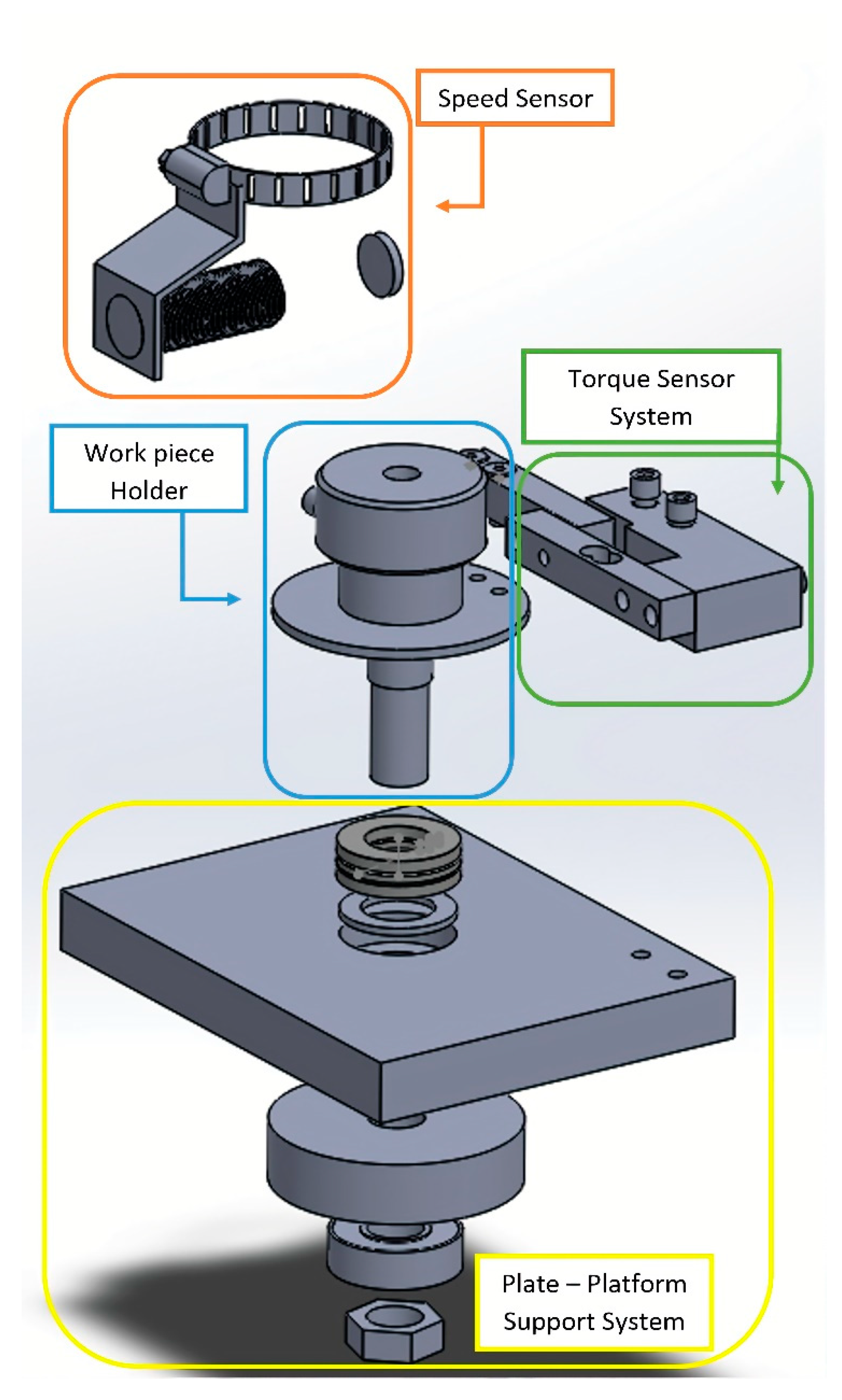
2.1. Design of the Modular Torque Measuring Device

The design of the modular torque measuring device included a workpiece holder, a torque sensor system, a speed sensor system, a modular support system, and an instrumentation system.

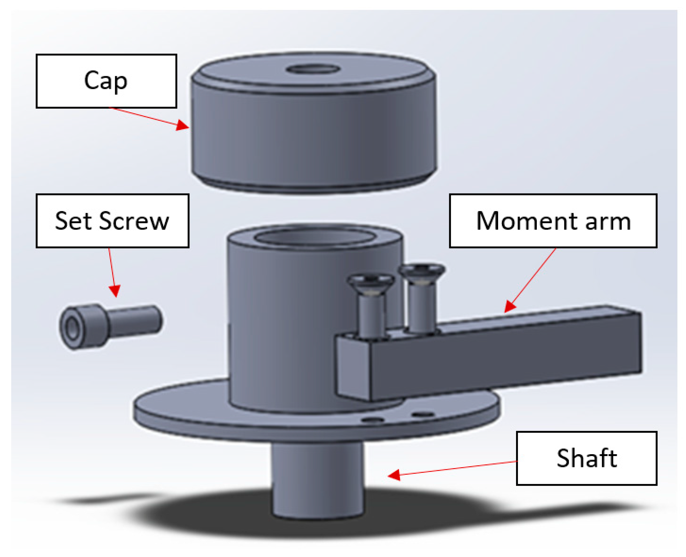
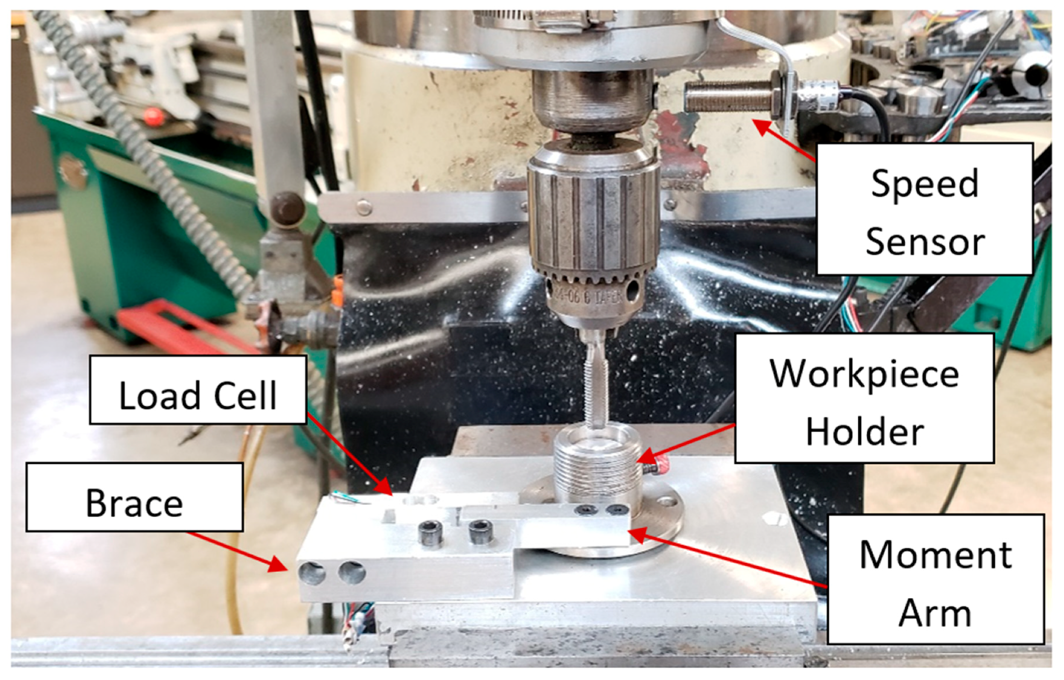
2.1.1. Workpiece Holder

The workpiece holder was designed to hold cylindrical specimens 25.4 mm in diameter by 25.4 mm in length. A schematic diagram of the workpiece holder is shown in Figure 1. To keep the workpiece in place, a set screw was used on the side of the specimen holder body. A workpiece cap was designed to minimize metal shavings from being ejected when testing with drilling and tapping tools. The workpiece cap contained a through-hole opening in the center to allow tools (taps or drill bits) to perform work while enclosing the chips to prevent any large strands of chips coming into contact with the operator. A shaft was included in the design to balance the workpiece holder on the support system as it rotates. A centered through-hole was drilled within the shaft to allow the tools performing work to exit properly without damaging the workpiece holder assembly, thus only allowing the workpieces to be machined. To measure torque, a moment arm was included in the design. The moment arm attached to the workpiece holder comes into contact with a load cell as the workpiece holder rotates during the tapping process. This contact transmits a force to the load cell, which is measured with the aid of an Arduino UNO microcontroller.

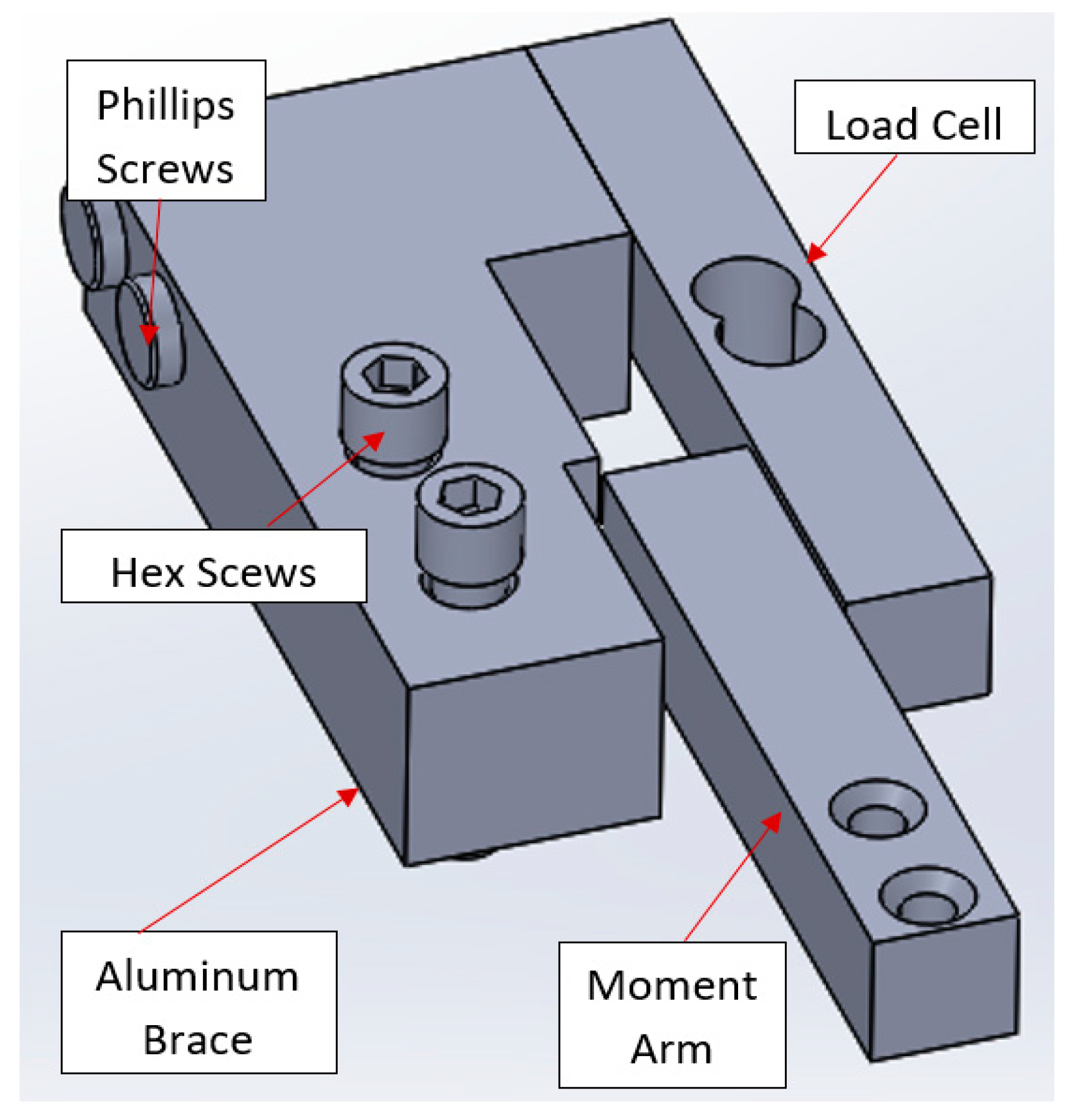
2.1.2. Torque Sensor Assembly

The torque sensor assembly included a load cell (20 kg maximum capacity) that was attached to a brace and adjusted to measure torque through an Arduino UNO microcontroller. When the moment arm exerts a force on the load cell, it sends a signal to the microcontroller through a HX711 signal amplifier. The load cell is supported by an aluminum brace, which was screwed tight onto the plate using a pair of hex screws. The non-secured component seen in Figure 1 represents the moment arm that was screwed onto the specimen holder. The moment from the tool attached to the chuck is transferred to the workpiece holder when it machines through the workpiece. This causes the workpiece to rotate, which causes the moment arm to rotate along with it. The rotation is stopped by the load cell and torque is calculated as follows:
T = F × d
where F is the force registered by the load cell and d is the length of the moment arm. Figure 2 shows a schematic diagram of the torque sensor assembly.

2.1.3. Speed Sensor System

The speed sensor system consisted of a Hall effect proximity sensor and was connected to an Arduino UNO microcontroller and a magnet. A hose clamp was utilized to attach the sensor onto quills of any size with the most common quill for milling machines. The Hall effect sensor was triggered based on the pulses of a magnet to calculate the rotational speed in revolutions per minute (rpm). The information gathered by the Hall effect sensor and the load cell was used to calculate the energy consumption as follows:
P = T × ω
where P is the power or energy consumption; T is the frictional torque measured with the torque sensor assembly; and ω is the angular measured with the speed sensor system. One requirement this system depends on is the distance between the proximity sensor and the magnet. In order for the proximity sensor to retrieve data, the distance between the two should not be greater than 10 mm. The Hall effect proximity sensor has a measurement accuracy of 0.1%. A schematic diagram of the speed sensor assembly is shown in Figure 3.

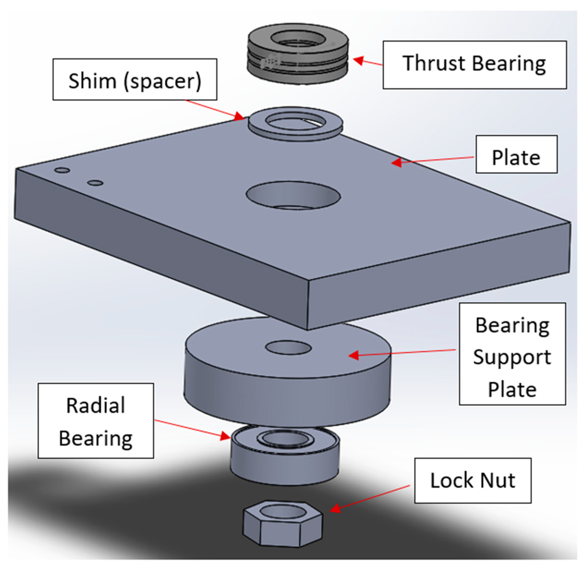
2.1.4. Modular Support System

Figure 4 shows a schematic diagram of the support system design. The support system is an essential component that acts as a platform to support all of the other components above it. The support system consists of an aluminum plate, which was milled to press fit a thrust bearing while supporting all the other components. The plate can be physically mounted in a drill press, a CNC, or a milling machine with nuts and bolts or a simple vise. A shim acts as a displacer by placing it inside the hole and contributing to a clearance of less than 1.59 mm. The top track of the bearing is then press-fitted into the workpiece holder. The two holes located on the upper right corner of the aluminum plate are meant to secure the torque sensor assembly. The center hole containing the press fitted thrust bearing and shim contains a follow up drilled hole, which is made throughout the remaining thickness of the plate. This hole allows the drill bit and tapping tools to perform work without damaging the shim and bearing as it exits.

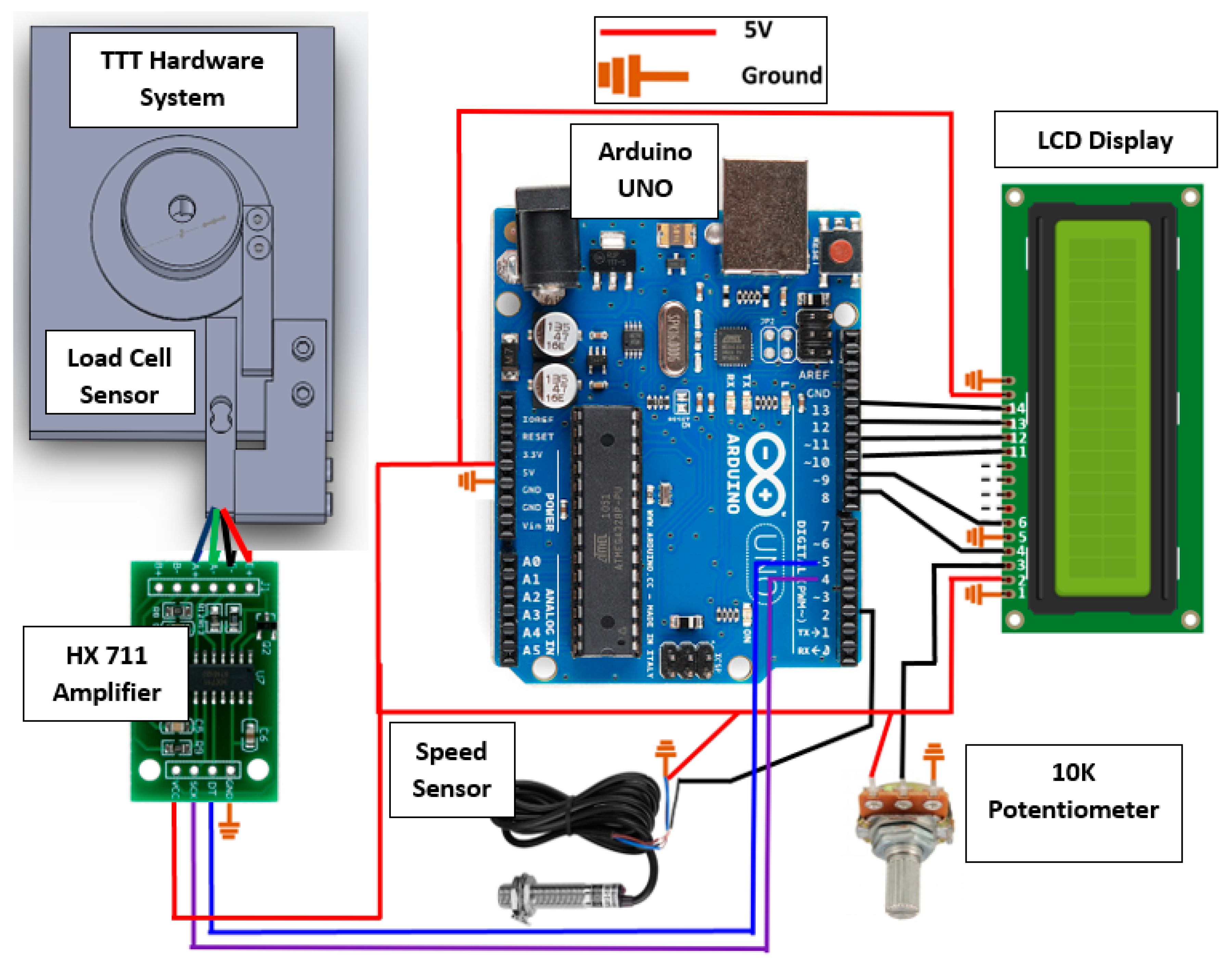
2.1.5. Instrumentation System

The instrumentation system included an Arduino UNO microcontroller, a HX711 signal amplifier, a 10 K potentiometer, and an LCD display. The information gathered by the speed sensor and the load cell was acquired by the microcontroller and manipulated to calculate torque and energy consumption. Information such as force, torque, power, and speed are displayed on the LCD screen in real time and sent to a PC through a USB connection. The potentiometer helps to clear the resolution from the LCD display. A diagram of the instrumentation system is shown in Figure 5.

2.1.6. Final Assembly

The principle behind the main function of the device relies on the product of force and distance to yield a torque. A workpiece fits inside the specimen holder and is tightened to it with a set screw. The specimen holder can rotate as it sits on a single direction thrust bearing and follow the moment that the tool creates. The moment arm is attached to the specimen holder and is responsible for transmitting the moment generated by the tool into a force that could be read by the load cell. The distance of the moment arm and the force registered by the load cell are used to calculate the frictional torque generated during the tapping operation. Figure 6 shows a schematic diagram of the final assembly.

2.2. Tapping Torque Validation Tests

Commercially available lubricants were used for the validation tests. Hydraulic Jack oil (ISO 22 mineral oil) was used as the reference oil. In addition, multipurpose mineral cutting oil (MobilMet 426) and biodegradable cutting oil (Bio-General Purpose Cut 40) were tested to gather information and compare the results for validation with the ASTM D-5619 standard. The properties of the different lubricants used in this study are shown in Table 1.
Tapping torque tests were conducted on a milling machine (Chevalier 3HP, model FM-3VS). The device was installed with a tapping torque set up according to ASTM D5619 (2011) [5]. The tests were conducted using 6061 aluminum cylindrical workpieces at the machining speed of 80 rpm. Tapping was performed using an uncoated high-speed steel tapping tool with the size of M10 × 1.5. Approximately, 1 mL of the lubricant was used to coat the tap tool prior to tapping and 2 mL was applied when the tap was halfway through the workpiece to lubricate the tapping process. Each tapping process was repeated four times for each lubricant, prior to averaging the thrust force and torque values. It is important to state that one tap was used per lubricant category. The percent efficiency of the test fluid was calculated according to the following equation, per ASTM D5619 (2011) [5]:
%   E f f i c i e n c y = M e a n   t o r q u e   o f   r e f e r e n c e   o i l M e a n   t o r q u e   o f   t e s t   f l u i d

3. Results and Discussion

3.1. Design of the Modular Torque Measurement Device

Figure 7 shows the actual testing device mounted on a conventional milling machine (Chevalier 3HP, model FM-3VS). The aluminum workpiece is set screwed inside the specimen holder as it is tapped. As a result, the specimen holder tends to rotate and when the workpiece is subjected to the torque of the tool as it acquires threads, the arm attached onto the specimen holder contacts the load cell to register a force. Each set of lubricant and workpieces had its own tap for experimentation.

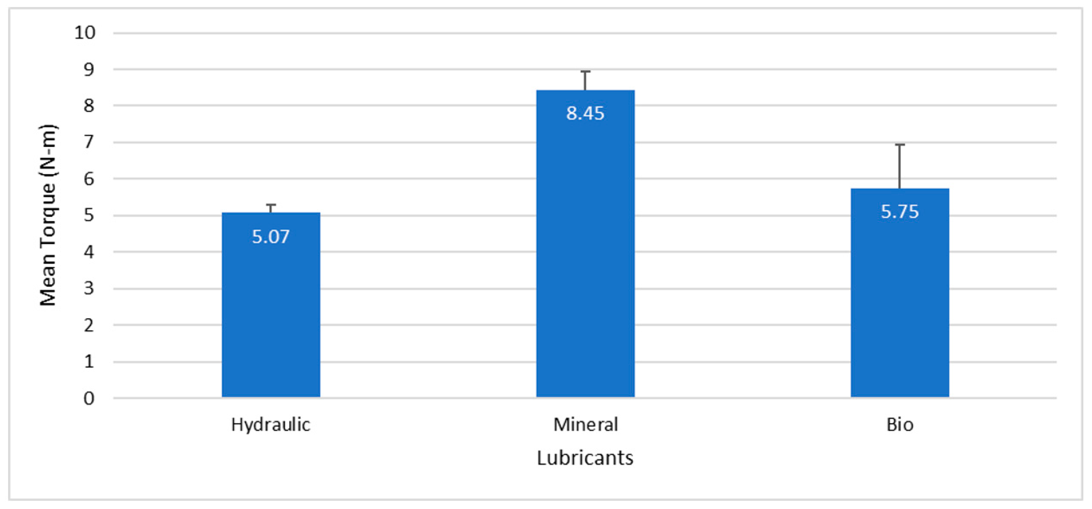
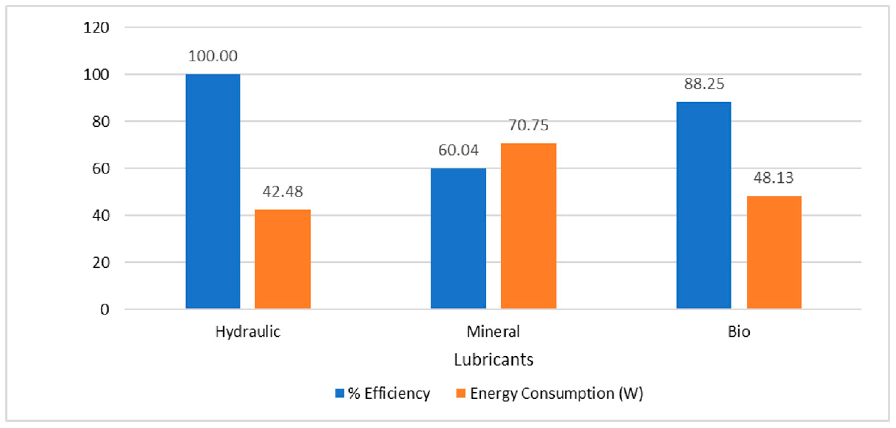
3.2. Tapping Torque Validation Tests

To validate the functionality of the proposed device, the performance of three different lubricants was evaluated and compared following the ASTM D5619 standard. The hole diameter in the different workpieces was constant at 8.5 mm. The taps used for testing were ultrasonically cleaned in acetone before the tapping tests. The influence of three tested lubricants on the tapping torque values is shown in Figure 8 and Figure 9. The tapping torque evolution as a function of time is shown in Figure 8. The average tapping torque values calculated per ASTM D5619 [5] for the different tested conditions are shown in Figure 9. The average tapping torque was evaluated when all active lobes of the tap were working to form the thread. This period corresponded to the steady state determined for these tests between seven and 13 seconds. Error bars in this figure represent the deviations.
As shown in Figure 8, during the tapping torque tests using Hydraulic Jack oil, as the tap progressed through the workpiece, the average torque increased from 4 to 6 N-m approximately during the steady state. In the case of the mineral oil, the maximum average torque ranged between 8 and 10 N-m. The torque registered using biodegradable lubricant seemed to decrease during the steady state. With the results, we can say that our instrument had the sensibility required to categorize different lubricants based on torque results, and to study the torque behavior of different lubricants during tapping operations.
A good repeatability of the tests is shown in the results presented in Figure 9. Error bars in the figure represent deviations calculated from four repetitions. The standard deviation values for the Hydraulic Jack, mineral, and biodegradable oils were 0.235, 0.489, and 1.186, respectively. The Hydraulic Jack oil used in the present study is the reference oil used in the ASTM D5619 [5]. The average torque values presented in the ASTM D5619 [5] for two tapping torque tests using the reference oil to tap 390 cast aluminum workpieces are 5.727 and 5. 782 N-m with standard deviations of 0.066 and 0.101, respectively. The average torque value obtained with the proposed device using the reference oil to tap 6061 aluminum workpieces was 5.07 N-m with a standard deviation of 0.235. This average torque value is slightly smaller than the one presented in the standard. The small difference could be due to different factors. One of them could be the mechanical properties of the workpiece material. Even though the workpieces were made of aluminum, they were made from different alloys.
On the other hand, Figure 10 shows the efficiency percent for each lubricant condition and the energy consumption. The efficiency percent was calculated using the Hydraulic Jack oil as the reference. The energy consumption was calculated using the torque values acquired with the load cell and the speed measured with the Hall effect sensor. In this case, the energy consumption was the power required by the milling machine to produce the threads on the workpiece. According to the results, energy consumption could be reduced up to 40% by using appropriate lubrication during threading.

4. Summary

In the present research project, a modular torque measuring instrument was designed, developed, and validated. This new instrument is capable of adapting to any conventional milling machine or CNC machine in order to perform tapping torque tests according to the ASTM D-5619 standard [5]. Additionally, a speed sensor was included in the design to calculate energy consumption during different industrial operations. To validate the instrument, three commercially available lubricants were evaluated.
Based on the experimental results, the following main conclusions can be drawn:
  • Results from the four tested conditions showed good repeatability with consistent results throughout the different tests for each lubricant.
  • Results obtained from the different tapping torque tests resembled the torque behavior reported for different lubricants on the ASTM D-5619 standard.
  • The addition of the speed sensor system to the instrument allowed for the experimental values of power or energy consumption to be determined during different industrial operations.
The impact of such a proposed instrument ranges between academic and industrial businesses. Such product affordability enables itself to remain a competitive option for tapping torque test (TTT) device manufacturers. The proposed instrument is a testing device designed to be compact, and can be used practically anywhere, whether in the research laboratory or in the field. There are current drill process tables, but none will relay beneficial information such as data on torque, heat, and spindle rpm. This design will give the user live critical and crucial information to inform the user and facilitate a decision to be made based on observations.

Author Contributions

Conceptualization, J.A.O.; Investigation, M.D.l.C., R.G., A.M., and J.A.O.; Methodology, M.D.l.C., R.G., J.A.G., and A.M.; Validation, J.A.G. and A.M.; Visualization, J.A.O.; Writing—original draft, M.D.l.C., R.G., and A.M.; Writing—review & editing, J.A.O..

Funding

This research received no external funding.

Acknowledgments

The authors would like to acknowledge the Department of Mechanical Engineering of The University of Texas Rio Grande Valley for their support on this project through the Senior Design Capstone course.

Conflicts of Interest

The authors declare no conflicts of interest.

References

  1. Podgornik, B.; Kosec, T.; Kocijan, A.; Donik, Č. Tribological Behaviour and Lubrication Performance of Hexagonal Boron Nitride (h-BN) as a Replacement for Graphite in Aluminium Forming. Tribol. Int. 2015, 81, 267–275. [Google Scholar] [CrossRef]
  2. Suresh Kumar Reddy, N.; Nouari, M.; Yang, M. Development of Electrostatic Solid Lubrication System for Improvement in Machining Process Performance. Int. J. Mach. Tools Manuf. 2010, 50, 789–797. [Google Scholar] [CrossRef]
  3. Hamdan, A.; Sarhan, A.A.D.; Hamdi, M. An Optimization Method of the Machining Parameters in High-Speed Machining of Stainless Steel Using Coated Carbide Tool for Best Surface Finish. Int. J. Adv. Manuf. Technol. 2012, 58, 81–91. [Google Scholar] [CrossRef]
  4. Sarhan, A.A.D.; Sayuti, M.; Hamdi, M. Reduction of Power and Lubricant Oil Consumption in Milling Process Using a New SiO2 Nanolubrication System. Int. J. Adv. Manuf. Technol. 2012, 63, 505–512. [Google Scholar] [CrossRef]
  5. D02 Committee. Test Method for Comparing Metal Removal Fluids Using the Tapping Torque Test Machine; ASTM International: West Conshohocken, PA, USA, 2011. [Google Scholar]
  6. Simmons, C.H.; Phelps, N.; Maguire, D.E. Manual of Engineering Drawing: Technical Product Specification and Documentation to British and International Standards, 4th ed.; Elsevier/Butterworth-Heinemann: Oxford, UK; Waltham, MA, USA, 2012. [Google Scholar]
  7. Ahn, J.H.; Lee, D.J.; Kim, S.H.; Kim, H.Y.; Cho, K.K. Effects of Synchronizing Errors on Cutting Performance in the Ultra-High-Speed Tapping. CIRP Ann. 2003, 52, 53–56. [Google Scholar] [CrossRef]
Figure 1. Workpiece holder schematic diagram.
Instruments 03 00041 g001
Figure 2. Torque sensor assembly.
Instruments 03 00041 g002
Figure 3. Speed sensor design.
Instruments 03 00041 g003
Figure 4. Support system design.
Instruments 03 00041 g004
Figure 5. Instrumentation system diagram.
Instruments 03 00041 g005
Figure 6. Final assembly.
Instruments 03 00041 g006
Figure 7. Testing device mounted on a milling machine during tapping torque test.
Instruments 03 00041 g007
Figure 8. Average tapping torque per lubricant categories.
Instruments 03 00041 g008
Figure 9. Average tapping torque.
Instruments 03 00041 g009
Figure 10. Energy consumption and % efficiency results.
Instruments 03 00041 g010
Table 1. Lubricants properties.
PropertiesHydraulic Jack OilMineral OilBiodegradable Oil
Viscosity, ASTM D 445
cSt @ 40 °C
21.53240
Pour Point, °C, ASTM D 97−46−15−18
Flash Point, °C, ASTM D 92157210218
Specific Gravity @ 15 °C kg/l, ASTM D 12980.9040.8740.900

