Permanent Magnet-Based Quadrupoles for Plasma Acceleration Sources

 ,
,
Abstract
1. Introduction
2. Quadrupole Characteristics
2.1. Gradient
2.2. Multipoles
3. Fixed Gradient Permanent Magnet Quadrupoles
3.1. Halbach Structure
3.2. Hybrid Quadrupole
4. Variable Permanent Magnet Quadrupoles
5. Built Quadrupoles
5.1. Fixed Gradient
- A 12-modified PM Halbach ring system in which four of them are half permanent magnet and half iron poles (II) is proposed at Kyoto University in collaboration with SLAC as a final focus lens for a positron-electron linear collider accelerator [41]. The system has a bore radius of 7 mm with a magnetic length of 100 mm generating a maximum gradient of 289 T/m. At the department für Physik, in München for a Table-Top FEL application, two 12 PM sector Halbach ring system of 17 mm (15 mm) magnetic length and 3 mm bore radius achieve a gradient of 500 T/m a [42].
- A 16-sector PM Halbach structure with a 33.5 mm bore radius, 92 mm magnetic length, 27.1 T/m gradient and 2.5 T integrated gradient have been built at CESR [43]. Three PMQs of the same design, each made up of a Halbach ring of 16 segments, have been installed in the PLEIADES ICS experiment as a final focus system [4]. The bore radius is very small (2.5 mm) with a magnetic length of 10.4 mm providing the largest gradient recorded using PM technology that is around 560 T/m alongside a focusing tunability through longitudinal movement of the magnets.
- A compact PMQ with a hybrid type design of interest for ultimate storage rings has been designed at ESRF [44]. The magnetic structure includes rectangular PM blocks and soft iron poles. A prototype with a bore radius of 12 mm and a magnetic length of 226 mm has been built (see Figure 9) provides a gradient of 85 T/m.
5.2. Variable Gradient
- A double Halbach ring structure of type (IV) was fabricated at Kyoto U. / SLAC collaboration for a final focus in a linear collider. The system consists of an inner hybrid ring with 8 sectors Halbach system and the outer ring being a pure 12-magnet Halbach structure rotating around the first one resulting in gradient variation from 17 T/m up to 120 T/m for a 230 mm magnetic length and 10 mm bore radius [45].
- A super hybrid quadrupole combining permanent magnetic material, coils and soft magnetic material has been built (see Figure 10) and tested for the new Brazilian Synchrotron Light Source (Sirius) [46]. The system has a bore radius of 27.5 mm and a magnetic length of 288 mm providing a maximum gradient of 28 T/m with a 30% tunability.
- An adjustable strength PM system has been built and tested, in collaboration between SLAC and Fermilab, for the Next Linear Collider. The system is based on four PM blocks and four soft iron poles of type (VI), with the possibility to retract linearly the permanent magnet blocks enabling an integrated gradient variation between 7 T and 68.7 T (gradient between 13 T/m and 115 T/m) for a 6.5 mm bore radius [47].
- A modified the 12-sector Halbach design composed of eight magnets and four poles surrounded by air-cooled electromagnetic coils as presented in Figure 11 has been proposed in the framework of CLIC/CERN collaboration [48]. The bore radius is 4.125 mm with a magnetic length of 300 mm achieving a maximum gradient of 610 T/m with 20% tunability.
- Two variable systems have been built in a collaboration of STFC Daresbury Laboratory and CERN for the Compact LInear Collider (CLIC) project [49,50] with an objective to collide electron-positron at an energy of 3 TeV. The first design, shown in Figure 12-left, provides a gradient from 15 to 60.4 T/m with a magnetic length of 241 mm. The second design, shown in Figure 12-right, provides a gradient from 2.9 to 43.8 T/m with a magnetic length of 194 mm length. The strength is adjusted by moving the PMs vertically away from the center, and by creating an air gap the gradient is reduced.
- Two variable quadrupoles are proposed for an interdigital H-mode drift tube linear accelerator using KONUS beam dynamics [51]: The first using an external adjustable electromagnets as shown in Figure 13-(left), with a bore radius of 12.5 mm providing a gradient from 50 to 100 T/m. The second using internal adjustable permanent magnets as shown in Figure 13-(right) that is similar to type (IV) but with additional number of segmented magnets. For a bore radius of 12.5 mm, the achieved gradient can be varied from 50 to 102 T/m.
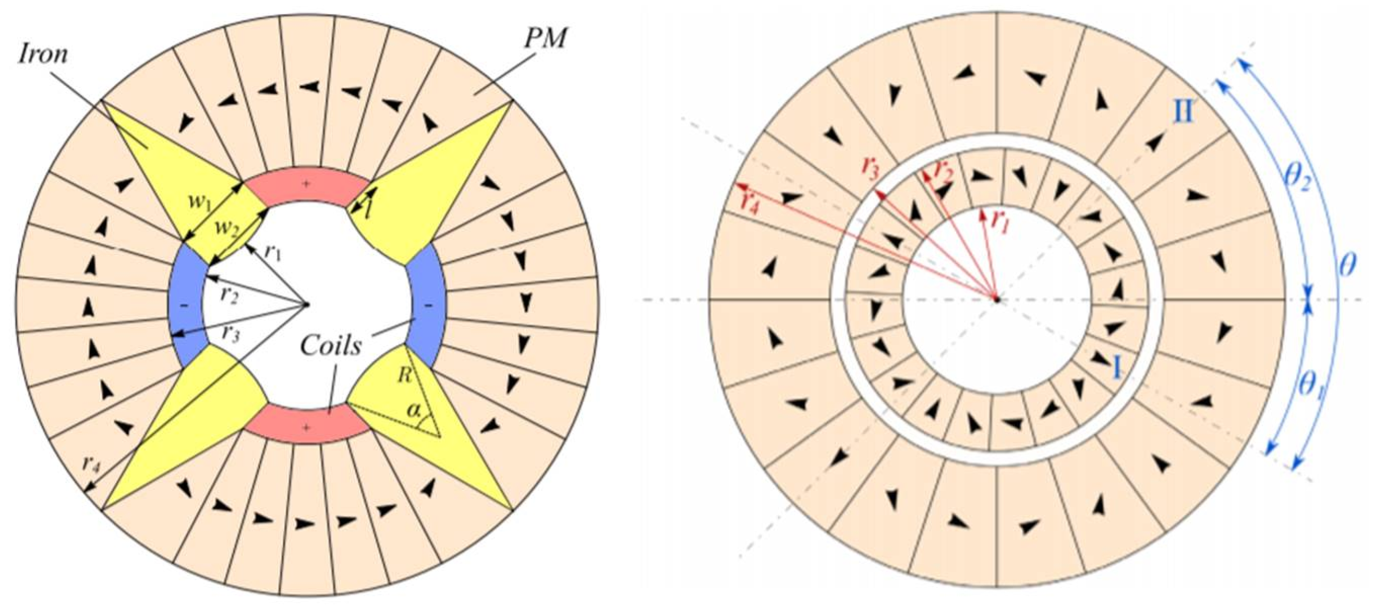
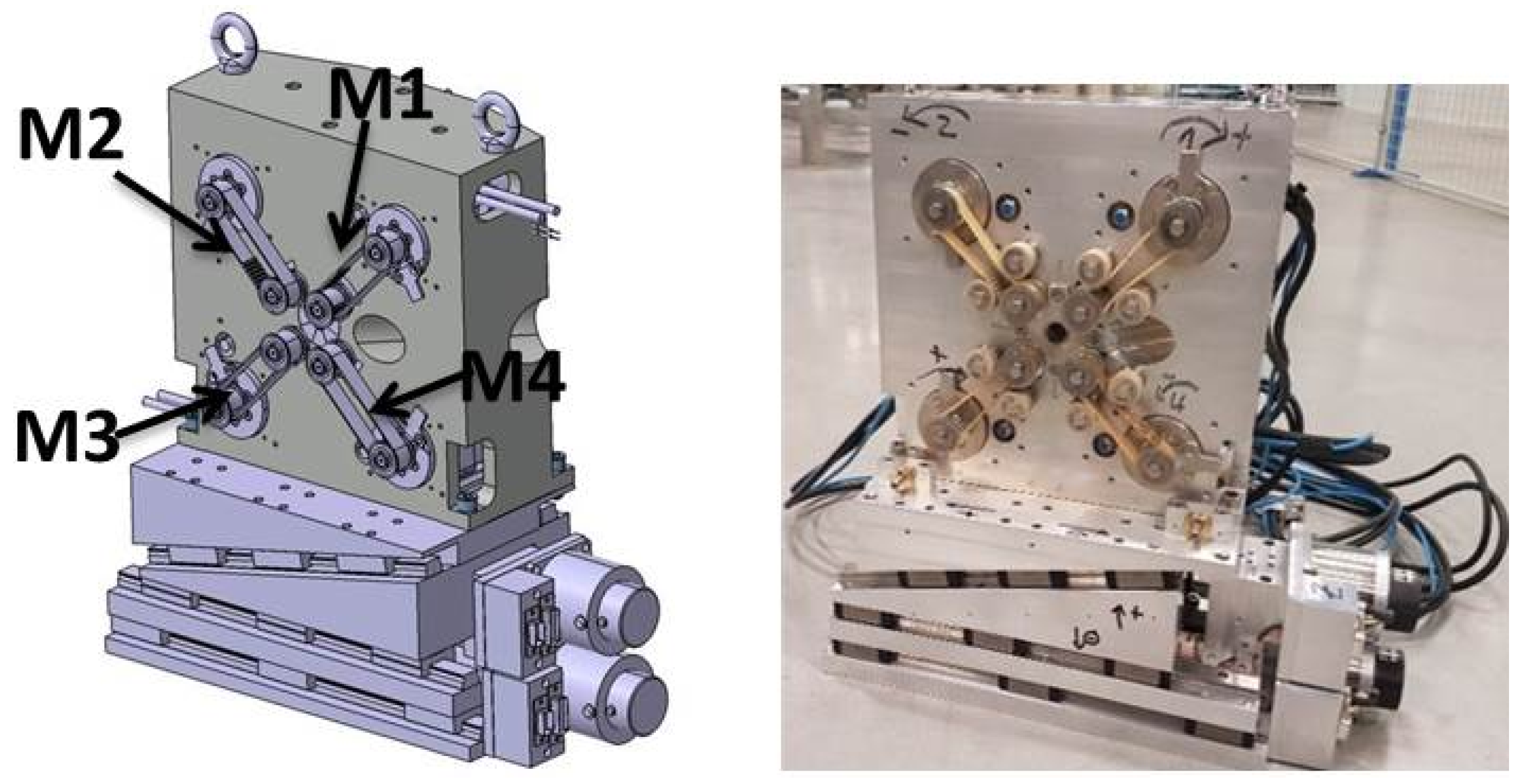
- Seven systems (QUAPEVA) of type (V) have been built in collaboration between SOLEIL and SigmaPhi [52,53] for the COXINEL project with an objective of FEL amplification using an LPA source. The QUAPEVA cosists of NdFeB magnets and permendur poles achieving a maximum gradient of 202 T/m and 45% tunability. The systems have a bore radius of 6 mm but with different magnetic lengths. Figure 14 presents the three particular configurations of the tuning magnets. The maximum and minimum gradient are obtained by orienting the tuning magnets easy axis towards the central magnetic poles. In these cases, the magnetic flux is either added (Figure 14a) or removed (Figure 14c) from the central poles. The average gradient is achieved when the tuning magnets are in the reference position, i.e. their easy axis is perpendicular to the central magnetic poles (Figure 14b). The QUAPEVAs are supported by translation tables (horizontal and vertical displacement) used to compensate any residual magnetic axis shift when varying the gradient, to perform electron beam based alignment [54,55]. The resulting mechanical design is shown in Figure 15 (left), also an assembled QUAPEVA on the translation table in Figure 15 (right).
5.3. Measurement
6. Summary
7. Conclusions
8. Patents
Author Contributions
Funding
Acknowledgments
Conflicts of Interest
References
- Tajima, T. Laser electron accelerator. Phys. Rev. Lett. 1979, 267, 1–10. [Google Scholar] [CrossRef]
- Leemans, W.P.; Gonsalves, A.J.; Mao, H.S.; Nakamura, K.; Benedetti, C.; Schroeder, C.B.; Tóth, C.; Daniels, J.; Mittelberger, D.E.; Bulanov, S.S.; et al. Multi-GeV Electron Beams from Capillary-Discharge-Guided Subpetawatt Laser Pulses in the Self-Trapping Regime. Phys. Rev. Lett. 2014, 113, 245002. [Google Scholar] [CrossRef] [PubMed]
- Wang, X.; Zgadzaj, R.; Fazel, N.; Li, Z.; Yi, S.A.; Zhang, X.; Henderson, W.; Chang, Y.Y.; Korzekwa, R.; Tsai, H.E.; et al. Quasi-monoenergetic laser-plasma acceleration of electrons to 2 GeV. Nat. Commun. 2013, 4, 1988. [Google Scholar] [CrossRef] [PubMed]
- Lim, J.; Frigola, P.; Travish, G.; Rosenzweig, J.B.; Anderson, S.G.; Brown, W.J.; Jacob, J.S.; Robbins, C.L.; Tremaine, A.M. Adjustable, short focal length permanent-magnet quadrupole based electron beam final focus system. Phys. Rev. Spec. Top.-Accel. Beams 2005, 8, 072401. [Google Scholar] [CrossRef]
- Migliorati, M.; Bacci, A.; Benedetti, C.; Chiadroni, E.; Ferrario, M.; Mostacci, A.; Palumbo, L.; Rossi, A.R.; Serafini, L.; Antici, P. Intrinsic normalized emittance growth in laser-driven electron accelerators. Phys. Rev. Spec. Top.-Accel. Beams 2013, 16, 011302. [Google Scholar] [CrossRef]
- Floettmann, K.; Paramonov, V.V. Beam dynamics in transverse deflecting rf structures. Phys. Rev. Spec. Top.-Accel. Beams 2014, 17, 024001. [Google Scholar] [CrossRef]
- Floettmann, K. Some basic features of the beam emittance. Phys. Rev. Spec. Top.-Accel. Beams 2003, 6, 034202. [Google Scholar] [CrossRef]
- Antici, P.; Bacci, A.; Benedetti, C.; Chiadroni, E.; Ferrario, M.; Rossi, A.R.; Lancia, L.; Migliorati, M.; Mostacci, A.; Palumbo, L.; et al. Laser-driven electron beamlines generated by coupling laser-plasma sources with conventional transport systems. J. Appl. Phys. 2012, 112, 044902. [Google Scholar] [CrossRef]
- Walker, P.A.; Alesini, P.D.; Alexandrova, A.S.; Anania, M.P.; Andreev, N.E.; Andriyash, I.; Aschikhin, A.; Assmann, R.W.; Audet, T.; Bacci, A.; et al. Horizon 2020 eupraxia design study. J. Phys. Conf. Ser. 2017, 874, 012029. [Google Scholar] [CrossRef]
- Gruner, F.; Becker, S.; Schramm, U.; Eichner, T.; Fuchs, M.; Weingartner, R.; Habs, D.; Meyer-ter-Vehn, J.; Geissler, M.; Ferrario, M.; et al. Design considerations for table-top, laser-based VUV and X-ray free electron lasers. Appl. Phys. B 2007, 86, 431–435. [Google Scholar] [CrossRef]
- Couprie, M.E.; Loulergue, A.; Labat, M.; Lehe, R.; Malka, V. Towards a free electron laser based on laser plasma accelerators. J. Phys. At. Mol. Opt. Phys. 2014, 47, 234001. [Google Scholar] [CrossRef]
- Schlenvoigt, H.-P.; Haupt, K.; Debus, A.; Budde, F.; Jäckel, O.; Pfotenhauer, S.; Schwoerer, H.; Rohwer, E.; Gallacher, J.G.; Brunetti, E.; et al. A compact synchrotron radiation source driven by a laser-plasma wakefield accelerator. Nat. Phys. 2008, 4, 130–133. [Google Scholar] [CrossRef]
- Fuchs, M.; Weingartner, R.; Popp, A.; Major, Z.; Becker, S.; Osterhoff, J.; Cortrie, I.; Zeitler, B.; Hörlein, R.; Tsakiris, G.D.; et al. Laser-driven soft-X-ray undulator source. Nat. Phys. 2009, 5, 826–829. [Google Scholar] [CrossRef]
- Anania, M.P.; Brunetti, E.; Wiggins, S.M.; Grant, D.W.; Welsh, G.H.; Issac, R.C.; Cipiccia, S.; Shanks, R.P.; Manahan, G.G.; Aniculaesei, C.; et al. An ultrashort pulse ultra-violet radiation undulator source driven by a laser plasma wakefield accelerator. Appl. Phys. Lett. 2014, 104, 264102. [Google Scholar] [CrossRef]
- Bonifacio, R.; Pellegrini, C.; Narducci, L.M. Collective instabilities and high-gain regime free electron laser. AIP Conf. Proc. 1984, 118, 236–259. [Google Scholar]
- Bonifacio, R.; De Salvo, L.; Pierini, P.; Piovella, N.; Pellegrini, C. Spectrum, temporal structure, and fluctuations in a high-gain free-electron laser starting from noise. Phys. Rev. Lett. 1994, 73, 70. [Google Scholar] [CrossRef] [PubMed]
- Huang, Z.; Kim, K.J. Three-dimensional analysis of harmonic generation in high-gain free-electron lasers. Phys. Rev. E 2000, 62, 7295. [Google Scholar] [CrossRef]
- Leemans, W.P.; Volfbeyn, P.; Guo, K.Z.; Chattopadhyay, S.; Schroeder, C.B.; Shadwick, B.A.; Lee, P.B.; Wurtele, J.S.; Esarey, E. Laser-driven plasma-based accelerators: Wakefield excitation, channel guiding, and laser triggered particle injection. Phys. Plasmas 1998, 5, 1615–1623. [Google Scholar] [CrossRef]
- Maier, A.R.; Meseck, A.; Reiche, S.; Schroeder, C.B.; Seggebrock, T.; Gruener, F. Demonstration scheme for a laser-plasma-driven free-electron laser. Phys. Rev. X 2012, 2, 031019. [Google Scholar] [CrossRef]
- Huang, Z.; Ding, Y.; Schroeder, C.B. Compact X-ray free-electron laser from a laser-plasma accelerator using a transverse-gradient undulator. Phys. Rev. Lett. 2012, 109, 204801. [Google Scholar] [CrossRef]
- Liu, T.; Zhang, T.; Wang, D.; Huang, Z. Compact beam transport system for free-electron lasers driven by a laser plasma accelerator. Phys. Rev. Accel. Beams 2017, 20, 020701. [Google Scholar] [CrossRef]
- Pellegrini, C. Free electron lasers: Development and applications. Part. Accel. 1990, 33, 159–170. [Google Scholar]
- Bennett, W.H. Magnetically self-focussing streams. Phys. Rev. 1934, 45, 890. [Google Scholar] [CrossRef]
- Rosenzweig, J.B.; Breizman, B.; Katsouleas, T.; Su, J.J. Acceleration and focusing of electrons in two-dimensional nonlinear plasma wake fields. Phys. Rev. A 1991, 44, R6189. [Google Scholar] [CrossRef] [PubMed]
- Chen, P. Grand disruption: A possible final focusing mechanism for linear colliders. Part. Accel. 1986, 20, 171–182. [Google Scholar]
- Lehe, R.; Thaury, C.; Guillaume, E.; Lifschitz, A.; Malka, V. Laser-plasma lens for laser-wakefield accelerators. Phys. Rev. Spec. Top.-Accel. Beams 2014, 17, 121301. [Google Scholar] [CrossRef]
- Thaury, C.; Guillaume, E.; Döpp, A.; Lehe, R.; Lifschitz, A.; Phuoc, K.T.; Gautier, J.; Goddet, J.P.; Tafzi, A.; Flacco, A.; et al. Demonstration of relativistic electron beam focusing by a laser-plasma lens. Nat. Commun. 2015, 6, 6860. [Google Scholar] [CrossRef] [PubMed]
- Panofsky, W.K.H.; Baker, W.R. A focusing device for the external 350-MeV proton beam of the 184-inch cyclotron at Berkeley. Rev. Sci. Instrum. 1950, 21, 445–447. [Google Scholar] [CrossRef]
- Röckemann, J.-H.; Schaper, L.; Barber, S.K.; Bobrova, N.A.; Boyle, G.; Bulanov, S.; Delbos, N.; Floettmann, K.; Kube, G.; Lauth, W.; et al. Direct measurement of focusing fields in active plasma lenses. Phys. Rev. Accel. Beams 2018, 21, 122801. [Google Scholar]
- Tauschwitz, A.; Yu, S.S.; Eylon, S.; Bangerter, R.O.; Leemans, W.; Peters, C.; Rasmussen, J.O.; Reginato, L.; Barnard, J.J.; Sharp, W.M. Plasma lens focusing and plasma channel transport for heavy ion fusion. Fusion Eng. Des. 1996, 32, 493–502. [Google Scholar] [CrossRef]
- Van Tilborg, J.; Steinke, S.; Geddes, C.G.R.; Matlis, N.H.; Shaw, B.H.; Gonsalves, A.J.; Huijts, J.V.; Nakamura, K.; Daniels, J.; Schroeder, C.B.; et al. Active plasma lensing for relativistic laser-plasma-accelerated electron beams. Phys. Rev. Lett. 2015, 115, 184802. [Google Scholar] [CrossRef] [PubMed]
- Pompili, R.; Anania, M.P.; Bellaveglia, M.; Biagioni, A.; Bini, S.; Bisesto, F.; Brentegani, E.; Cardelli, F.; Castorina, G.; Chiadroni, E.; et al. Focusing of High-Brightness Electron Beams with Active-Plasma Lenses. Phys. Rev. Lett. 2018, 121, 174801. [Google Scholar] [CrossRef] [PubMed]
- Nakanii, N.; Hosokai, T.; Iwasa, K.; Masuda, S.; Zhidkov, A.; Pathak, N.; Nakahara, H.; Mizuta, Y.; Takeguchi, N.; Kodama, R. Transient magnetized plasma as an optical element for high power laser pulses. Phys. Rev. Spec. Top.-Accel. Beams 2015, 18, 021303. [Google Scholar] [CrossRef]
- Marocchino, A.; Anania, M.P.; Bellaveglia, M.; Biagioni, A.; Bini, S.; Bisesto, F.; Brentegani, E.; Chiadroni, E.; Cianchi, A.; Croia, M.; Di Giovenale, D. Experimental characterization of the effects induced by passive plasma lens on high brightness electron bunches. Appl. Phys. Lett. 2017, 111, 184101. [Google Scholar] [CrossRef]
- Van Tilborg, J.; Barber, S.K.; Tsai, H.E.; Swanson, K.K.; Steinke, S.; Geddes, C.G.R.; Gonsalves, A.J.; Schroeder, C.B.; Esarey, E.; Bulanov, S.S.; et al. Nonuniform discharge currents in active plasma lenses. Phys. Rev. Accel. Beams 2017, 20, 032803. [Google Scholar] [CrossRef]
- Chubar, O.; Elleaume, P.; Chavanne, J. A three-dimensional magnetostatics computer code for insertion devices. J. Synchrotron Radiat. 1998, 5, 481–484. [Google Scholar] [CrossRef] [PubMed]
- Halbach, K. Design of permanent multipole magnets with oriented rare earth cobalt material. Nucl. Instrum. Methods 1980, 169, 1–10. [Google Scholar] [CrossRef]
- Givord, D.; Li, H.; De La Bâthie, R.P. Magnetic properties of y2fe14b and nd2fe14b single crystals. Solid State Commun. 1984, 51, 857–860. [Google Scholar] [CrossRef]
- Benabderrahmane, C.; Berteaud, P.; Valléau, M.; Kitegi, C.; Tavakoli, K.; Béchu, N.; Mary, A.; Filhol, J.M.; Couprie, M.E. Nd2Fe14B and Pr2Fe14B magnets characterisation and modelling for cryogenic permanent magnet undulator applications. Nucl. Instrum. Methods Phys. Res. Sect. A Accel. Spectrom. Detect. Assoc. 2012, 669, 1–6. [Google Scholar] [CrossRef]
- Hiroyoshi, H.; Yamada, M.; Saito, N.; Kato, H.; Nakagawa, Y.; Hirosawa, S.; Sagawa, M. High-field magnetization and crystalline field of R2Fe14B and R2Co14B. J. Magn. Magn. Mater. 1987, 70, 337–339. [Google Scholar] [CrossRef]
- Mihara, T.; Iwashita, Y.; Kumada, M.; Evgeny, A.; Spencer, C.M. Super strong permanent magnet quadrupole for a linear collider. IEEE Trans. Appl. Supercond. 2004, 14, 469–472. [Google Scholar] [CrossRef]
- Eichner, T.; Grüner, F.; Becker, S.; Fuchs, M.; Habs, D.; Weingartner, R.; Schramm, U.; Backe, H.; Kunz, P.; Lauth, W. Miniature magnetic devices for laser-based, table-top free-electron lasers. Phys. Rev. Spec. Top.-Accel. Beams 2007, 10, 082401. [Google Scholar] [CrossRef]
- Lou, W.; Hartill, D.; Rice, D.; Rubin, D.; Welch, J. Stability considerations of permanent magnet quadrupoles for cesr phase-iii upgrade. Phys. Rev. Spec. Top.-Accel. Beams 1998, 1, 022401. [Google Scholar] [CrossRef]
- N’gotta, P.; Le Bec, G.; Chavanne, J. Hybrid high gradient permanent magnet quadrupole. Phys. Rev. Accel. Beams 2016, 19, 122401. [Google Scholar] [CrossRef]
- Mihara, T.; Iwashita, Y.; Kumada, M.; Spencer, C.M. Variable permanent magnet quadrupole. IEEE Trans. Appl. Supercond. 2006, 16, 224–227. [Google Scholar] [CrossRef]
- Tosin, G.; Sanchez, P.P.; Citadini, J.F.; Vergasta, C.C. Super hybrid quadrupoles. Nucl. Instrum. Methods Phys. Res. Sect. A Accel. Spectrom. Detect. Assoc. 2012, 674, 67–73. [Google Scholar] [CrossRef][Green Version]
- Gottschalk, S.C.; Taylor, D.J. Magnetic and engineering analysis of an adjustable strength permanent magnet quadrupole. In Proceedings of the Particle Accelerator Conference, PAC 2005, Knoxville, TN, USA, 16–20 May 2005; pp. 2122–2124. [Google Scholar]
- Modena, M.; Garcia Perez, J.; Thonet, P.; Petrone, C.; Vorozhtsov, A.; Dunkel, O.; Solodko, E.; Tommasini, D. Design, assembly and first measurements of a short model for clic final focus hybrid quadrupole qd0. In Proceedings of the 3rd International Particle Accelerator Conference, New Orleans, LA, USA, 20–25 May 2012; Volume 1205201. [Google Scholar]
- Shepherd, B.; Clarke, J.; Collomb, N. Construction and measurement of novel adjustable permanent magnet quadrupoles for clic. Proceedings of IPAC2012, New Orleans, LA, USA, 20–25 May 2012. [Google Scholar]
- Clarke, J.A.; Collomb, N.A.; Shepherd, B.J.; Stokes, D.G.; Bartalesi, A.; Modena, M.; Struik, M. Novel tunable permanent magnet quadrupoles for the CLIC drive beam. IEEE Trans. Appl. Supercond. 2014, 24, 1–5. [Google Scholar] [CrossRef]
- Easton, M.J.; Li, H.; Lu, Y.; Zhu, J.; Pfister, P.D. Permanent-magnet quadrupoles for an interdigital H-mode drift tube linear accelerator: Optimization code and adjustable magnet design. Phys. Rev. Accel. Beams 2018, 21, 122401. [Google Scholar] [CrossRef]
- Marteau, F.; Ghaith, A.; N’Gotta, P.; Benabderrahmane, C.; Valléau, M.; Kitegi, C.; Loulergue, A.; Vétéran, J.; Sebdaoui, M.; André, T.; Le Bec, G.; et al. Variable high gradient permanent magnet quadrupole (QUAPEVA). Appl. Phys. Lett. 2017, 111, 253503. [Google Scholar] [CrossRef]
- Ghaith, A.; Kitegi, C.; André, T.; Valléau, M.; Marteau, F.; Vétéran, J.; Blache, F.; Benabderrahmane, C.; Cosson, O.; Forest, F.; et al. Tunable High Gradient Quadrupoles For A Laser Plasma Acceleration Based FEL. arXiv 2017, arXiv:1712.03857. [Google Scholar] [CrossRef]
- Couprie, M.E.; Labat, M.; Evain, C.; Marteau, F.; Briquez, F.; Khojoyan, M.; Benabderrahmane, C.; Chapuis, L.; Hubert, N.; Bourassin-Bouchet, C.; et al. An application of laser–plasma acceleration: Towards a free-electron laser amplification. Plasma Phys. Control. Fusion 2016, 58, 034020. [Google Scholar] [CrossRef]
- André, T.; Andriyash, I.A.; Loulergue, A.; Labat, M.; Roussel, E.; Ghaith, A.; Khojoyan, M.; Thaury, C.; Valléau, M.; Briquez, F.; et al. Control of laser plasma accelerated electrons for light sources. Nat. Commun. 2018, 9, 1334. [Google Scholar] [CrossRef] [PubMed]
- Le Bec, G.; Chavanne, J.; Penel, C. Stretched wire measurement of multipole accelerator magnets. Phys. Rev. Spec. Top.-Accel. Beams 2012, 15, 022401. [Google Scholar] [CrossRef]
- Iwashita, Y.; Mihara, T.; Antokhin, E.; Kumada, M.; Aoki, M. Permanent magnet quadrupole for final focus for linear collider. In Proceedings of the 2003 Particle Accelerator Conference, Portland, OR, USA, 12–16 May 2003. [Google Scholar]
- Mihara, T. A Super Strong Permanent Magnet Quadrupole for the Final Focus in a Linear Collider; Tech. Rep.; SLAC National Accelerator Lab.: Menlo Park, CA, USA, 2018. [Google Scholar]
- Cesar, D.; Maxson, J.; Musumeci, P.; Sun, Y.; Harrison, J.; Frigola, P.; O’Shea, F.H.; To, H.; Alesini, D.; Li, R.K. Demonstration of single-shot picosecond time-resolved MeV electron imaging using a compact permanent magnet quadrupole based lens. Phys. Rev. Lett. 2016, 117, 024801. [Google Scholar] [CrossRef] [PubMed]
- Zhou, Z.; Tang, C.; Rui, T.; Du, Y.C.; Li, F.; Gai, W.; Huang, W. Compact High Energy Electron Radiography System Based on Permanent Magnet Quadrupole. In Proceedings of the International Particle Accelerator Conference (IPAC’17), Copenhagen, Denmark, 14–19 May 2017; JACOW: Geneva, Switzerland, 2017. [Google Scholar]
- Pompili, R.; Anania, M.P.; Chiadroni, E.; Cianchi, A.; Ferrario, M.; Lollo, V.; Notargiacomo, A.; Picardi, L.; Ronsivalle, C.; Rosenzweig, J.B.; et al. Compact and tunable focusing device for plasma wakefield acceleration. Rev. Sci. Instrum. 2018, 89, 033302. [Google Scholar] [CrossRef] [PubMed]
- Iwashita, Y.; Mihara, T.; Kyoto, U.; Kumada, J.M.; NIRS, C.; Spencer, J.C. Super strong adjustable permanent magnet quadrupole for the final focus in a linear collider. In Proceedings of the 10th European Particle Accelerator Conference, EPAC, Edinburgh, UK, 26–30 June 2006; Volume 6, pp. 2550–2552. [Google Scholar]
- Benabderrahmane, C.; Couprie, M.E.; Forest, F.; Sigmaphi, O.C. Multi-pôle magnétique réglable. Patent WO2016034490, 10 March 2016. [Google Scholar]
- Benabderrahmane, C.; Couprie, M.E.; Forest, F.; Sigmaphi, O.C. Adjustable Magnetic Multipole. Europe Patent WOBL14SSOQUA/CA, 27 August 2015. [Google Scholar]


| Parameter | Value | Unit | |
|---|---|---|---|
| Magnet | NdFeB | ||
| 1.26 | T | ||
| Materials | Coercivity | 1830 | kA/m |
| Pole | Vanadium Permendur | ||
| Saturation | 2.35 | T | |
| 6 | mm | ||
| Geometry | 17 | mm | |
| L | 100 | mm |
| QUAPEVAs | Magnetic Length [mm] | Gradient [T/m] | [%] |
|---|---|---|---|
| Q1 | 26 | 196 | −5.1 |
| Q2 | 40.7 | 202 | −4 |
| Q3 | 44.7 | 203 | −3.5 |
| Q4 | 47.1 | 204 | −3.3 |
| Q5 | 66 | 208 | −1.8 |
| Q6 | 81 | 209 | −1.3 |
| Q7 | 100 | 211 | −0.28 |
| Multipole | Radia [T·mm] | Measurement [T·mm] | [%] |
|---|---|---|---|
| b | 0.021 | 0.039 | 48 |
| b | 84.68 | 84.45 | −0.28 |
| b | 1.93 | 1.86 | −3.6 |
| b | −1.46 | −1.02 | 30 |
| Type | n° Magnets | n° Poles | Max G | Integ G | G/G |
|---|---|---|---|---|---|
| Halbach | 4 | - | 78 T/m | 7.8 T | - |
| Halbach | 8 | - | 207 T/m | 20.7 T | - |
| Halbach | 12 | - | 237 T/m | 23.7 T | - |
| Hybrid-I | 4 | 4 | 166 T/m | 16.6 T | - |
| Hybrid-II | 4 + 4 halves | 4 halves | 211 T/m | 21.1 T | - |
| Hybrid-III | 12 | 4 halves + ring | 227 T/m | 22.7 T | - |
| Hybrid-IV | 4 + ring | 4 | 201 T/m | 20.1 T | 34% |
| Hybrid-V | 4 + 4 cylinders | 4 | 185 T/m | 18.5 T | 20% |
| Hybrid-VI | 4 | Bulk | 100 T/m | 10 T | 90% |
| Project | Lab | Radius | L | Max G | integ G | G/G | References |
|---|---|---|---|---|---|---|---|
| Storage ring | CESR | 33.5 mm | 92 mm | 27 T/m | 2.5 T | - | [43] |
| PLEIADES ICS | Lawrence Livermore | 2.5 mm | 10.4 mm | 560 T/m | 5.8 T | - | [4] |
| LINEAR COLLIDER | Kyoto University | 7 mm | 100 mm | 300 T/m | 28.5 T | - | [41,57,58] |
| SPTEM | UCLA | 3.5 mm | 6.16 mm | 600 T/m | 3.3 T | - | [59] |
| Radiography | Tsinghua University | 5 mm | 20 mm | 287 T/m | 5.74 T | - | [60] |
| Storage Ring | ESRF | 12 mm | 226 mm | 82 T/m | 18.6 T | - | [44] |
| Table-Top FEL | LMU Munich | 3 mm | 17 mm | 500 T/m | 8.5 T | - | [42] |
| LPA | SPARC LAB | 3 mm | 20.2 | 519 | 10.5 T | - | [61] |
| LINEAR COLLIDER | Kyoto/NIRS | 10 mm | 200 mm | 120 T/m | 24.2 T | 85% | [45,62] |
| CLIC | CERN | 4.125 mm | 273 mm | 610 T/m | 172.5 | 20% | [48] |
| CLIC | CERN/STFC | 13.6 mm | 214 mm | 60.4 T/m | 14.6 T | 75% | [49] |
| CLIC | CERN/STFC | 13.6 mm | 194 mm | 43.8 T/m | 8.5 T | 93% | [49] |
| Next Linear Collider | STI/SLAC | 6.5 mm | 420 mm | 163 T/m | 68.7 T | 90% | [47] |
| COXINEL | SOLEIL | 6 mm | 100 mm | 210 T/m | 21 T | 44% | [52,53] |
| linear accelerator | Peking University | 12.5 mm | - | 100 T/m | - | 50% | [51] |
© 2019 by the authors. Licensee MDPI, Basel, Switzerland. This article is an open access article distributed under the terms and conditions of the Creative Commons Attribution (CC BY) license (http://creativecommons.org/licenses/by/4.0/).
Share and Cite
Ghaith, A.; Oumbarek, D.; Kitégi, C.; Valléau, M.; Marteau, F.; Couprie, M.-E. Permanent Magnet-Based Quadrupoles for Plasma Acceleration Sources. Instruments 2019, 3, 27. https://doi.org/10.3390/instruments3020027
Ghaith A, Oumbarek D, Kitégi C, Valléau M, Marteau F, Couprie M-E. Permanent Magnet-Based Quadrupoles for Plasma Acceleration Sources. Instruments. 2019; 3(2):27. https://doi.org/10.3390/instruments3020027
Chicago/Turabian StyleGhaith, Amin, Driss Oumbarek, Charles Kitégi, Mathieu Valléau, Fabrice Marteau, and Marie-Emmanuelle Couprie. 2019. "Permanent Magnet-Based Quadrupoles for Plasma Acceleration Sources" Instruments 3, no. 2: 27. https://doi.org/10.3390/instruments3020027
APA StyleGhaith, A., Oumbarek, D., Kitégi, C., Valléau, M., Marteau, F., & Couprie, M.-E. (2019). Permanent Magnet-Based Quadrupoles for Plasma Acceleration Sources. Instruments, 3(2), 27. https://doi.org/10.3390/instruments3020027