1. Introduction
Cancer therapy, involving medical accelerators, has the potential to enhance healthcare benefits for patients. Proton therapy shows significant advantages in the dose distribution profile, described by the Bragg peak, in comparison to radiotherapy with photons or electrons. Online beam monitoring is essential to ensure patient safety as well as a high quality and efficacious treatment. As such, the energy, energy spread, current, position and lateral profile of the beam must be precisely determined and recorded.
Ionisation chambers are the current practice in particle therapy to monitor the beam [
1]. However, while such detectors are robust and easy to operate, they require daily calibration and their response time is slow, despite efforts to optimise material and readout time [
2]. Therefore, alternative instruments using fast silicon detectors are being explored. Developments are ongoing and, in [
3], Sadrozinski et al. proposed an ultra-fast silicon detector with 10 μm spatial resolution and 10 ps time resolution. Moreover, the Timepix pixel readout chip, developed by the CERN Medipix Collaboration, has previously been used to detect and characterise secondary radiation from hadron therapy beams [
4], but these approaches are still directly interacting with the beam. A standalone online beam monitor for current and future medical beamlines using the Vertex Locator (VELO) detector technology from the Large Hadron Collider beauty experiment (LHCb) is being investigated for a non-interceptive approach. The VELO sensor is used for reconstructing charged particle trajectories and production and decay vertices of particles originating from collisions at the LHCb experiment at CERN [
5]. Due to the semi-circular cut-out in the sensor design, a precise measurement of the beam halo without interfering with the beam core is possible. If the beam halo reading is correlated with an ionisation chamber or Faraday Cup, a halo-dose correlation data bank for different settings can be established and used for quality assurance without the need of ion-chambers. Assuming a symmetric beam profile, the comparison between the two semi circular halos will provide the information of the beam profile.
The transition of the VELO detector technology from the LHC environment to a standalone system is necessary to meet the specific conditions of the clinical environment of the 60 MeV proton therapy beamline at the Clatterbridge Cancer Centre (CCC), UK. Several adaptations are described, including the venting, cooling and positioning system of VELO modules and the development of a synchronised readout system.
2. Materials and Methods
2.1. LHCb VELO Technology
The LHCb VELO technology at CERN [
5] is used to reconstruct production and decay vertices of beauty and charm hadrons [
6]. The VELO module was designed according to the requirements of operating in the harsh LHCb environment. Thus, it had to operate in vacuum conditions within the LHC beam pipe and withstand the extreme radiation environment with over 300 kGy (Private communications with David Hutchcroft, University of Liverpool, UK) accumulated dose during the LHC runs [
7].
Each VELO module comprises a semi-circular silicon micro-strip detector with 300 μm thick silicon of type
[
6]. A schematic of the VELO sensor is shown in
Figure 1a and a photo of the adapted modules outside the LHC environment is shown in
Figure 1b. The VELO module combines two sensor types that are glued to each other with a different strip geometry, the
R-sensor and
-sensor. Each sensor has 2048 strips with an active area covered by an inner radius of 8.2 mm and an outer radius of 42 mm. The
R-sensor is divided into four +45° sectors each with 512 concentric semi-circular segmented strips, where the inner pitch of 40 μm increases linearly to an outer pitch of 108 μm. Thus, it provides the radial position information relative to the origin of the beam axis. The
ϕ-sensor is divided into two sectors with 683 strips in the inner sector and 1365 strips in the outer sector. The strips are tilted with a stereo angle in a dog-leg shape providing angular position information with an angular coverage of 182°. As a result, the geometry enables precise measurements of particle tracks in polar coordinates.
The readout electronics of the VELO modules consist of a chain of analogue and digital parts to transfer and process the collected signals from the sensor.
The Beetle chips [
8], the front end (FE) analogue readout chips, integrate the signals received from the sensors, amplify them and process them to the repeater boards. The front end pulse shape is a semi-Gaussian pulse and is sampled with the LHC bunch-crossing frequency of 40 MHz into a 160 deep analogue pipeline for each strip. The Beetle chips are controlled by an I
2C interface. The operation of the chips produces approximately 27.5 W of heat per sensor that needs to be dissipated. Liquid CO
2 cooling in the LHC is used to achieve a continuous temperature of −7 °C of the silicon sensors to avoid overheating and damage [
9]. The waste heat is taken away by evaporators, small rectangular aluminium blocks with embedded coolant pipes inside that attach on the base of the detector. The CO
2 supply into the evaporator is realised by the 2-Phase Accumulator Controlled Loop (2PACL) method.
The repeater boards are responsible for forwarding the I
2C signals to the digitiser boards and distributing low and high voltage to the modules. The Trigger Electronics and Level 1 (TELL1) boards perform the digitisation with 10 bit ADCs sampling at 40 MHz of the analogue data and process them further [
10]. The data are in a non-zero-suppressed (NZS) format carrying the full raw data information. Processing of the data includes channel reordering and correcting pedestal and header crosstalk. Furthermore, TELL1 boards send out I
2C commands for initiating the data acquisition of the Beetle chips and readout triggers. Ultimately, the processed data are then stored in buffers until a transfer is initiated to a computer by a High Level Trigger (HLT).
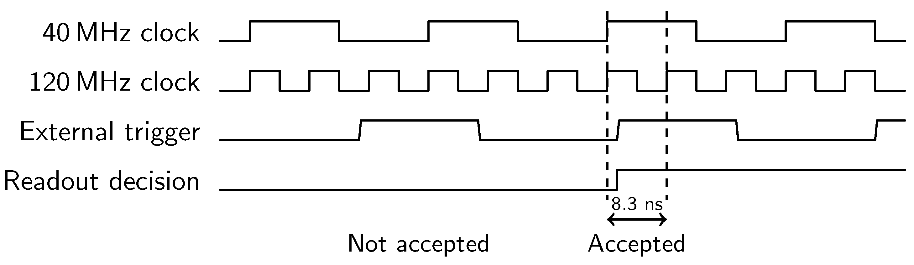
2.2. Trigger and Timing Control for the LHCb VELO Modules
The standalone setup of the VELO modules requires modification for synchronisation of the readout and therefore, a closer look at the VELO timing and trigger system and its configuration is needed [
11,
12].
The readout electronics were designed to work in synchronism with the LHC bunch crossing frequency,
. To ensure this, a Timing and Fast Control (TFC) [
13] system was installed in the LHCb experiment to distribute the LHC clock and synchronous reset and control commands to the FE electronics. As mentioned, Beetle chips sample events every 25 ns and store them in the pipeline with a column number (PCN) of up to 160 for each strip. The sampling is configured with the standard LHCb latency time of 160 clock cycles (one clock cycle is 25 ns). As a result, an event in a specific PCN that was recorded exactly 4 μs before, is retrieved by the readout (Level(L)0) trigger sent out by the TELL1 board at a maximum of 1.1 MHz data transfer frequency. The trigger timing is controlled by the readout supervisor ODIN [
14], which broadcasts the clock to the Timing Trigger and Control receiver on the TELL1 board. This ensures the digitising is synchronous to the sampling of the Beetle chips. The decision to transfer the data to the storing computer is completed by a L1 trigger which is a software based trigger. It uses information from the VELO FE electronics and trigger and time subdetectors, matching them to the previously selected events by the L0 trigger.
For the standalone VELO sensor, neither the TFC system nor the ODIN readout supervisor is available. The process involved in achieving synchronisation is discussed in
Section 3.2.
2.3. Requirements for the VELO Modules in a Clinical Proton Beamline
The proposed site of implementation is the 60 MeV proton therapy beamline at the Clatterbridge Cancer Centre (CCC). The proton centre has been treating ocular tumours since 1989, making it the world’s first hospital-based proton facility [
15]. The passively scattered proton beam is delivered through a fixed beamline from a 62 MeV MC-60 cyclotron, Scanditronix SA, Uppsala, Sweden. Parameters of the proton beam and its time structure are summarised in
Table 1.
The optimal area for the integration of the VELO detector modules in the treatment line is between the modulator box exit and the diagnostic box entrance (see
Figure 2). To evaluate the integration of the VELO module within this zone, preliminary simulation studies were performed using the Monte Carlo simulation toolkit, Geant4 (GEometry ANd Tracking). These simulations offer an overview of the beam propagation, extent of halo and give an idea about the interaction with the VELO module.
In addition, for the beam halo measurements in CCC and with reference to the integration area, the following requirements were necessary for the performance and positioning of the detector.
Operation of the detector in ambient air for temperatures of the sensors below 0 °C to prevent degradation of the silicon sensor and suppress noise.
Positioning of the detector in the beam propagation direction z and its transverse plane x with an accuracy of 1 mm.
Alignment of the VELO module co-centrically with the beam z-axis with an accuracy of 1 mm.
Configuration of a new set of delay parameters in clock cycles for correct data sampling of the VELO modules due to hardware and cable changes in the new environment.
Matching the readout of the VELO module with the proton bunch arrival given by the RF frequency of the CCC cyclotron of 25.7 MHz to sample at positive points of the output pulse.
Conceptualisation of a synchronised readout of the VELO modules with a Faraday Cup.
3. Results
Several changes in the system setup were necessary to operate the VELO detector modules as a standalone system outside of the LHC environment as stated above. Two VELO modules (see
Figure 1b) were utilised for this adapted system and set up in a laboratory in the Cockcroft Institute. The achieved result of the system regarding cooling, spatial alignment, calibration and readout are presented in the following sections. This leads to a description of the fully optimised system for the integration in the CCC beamline.
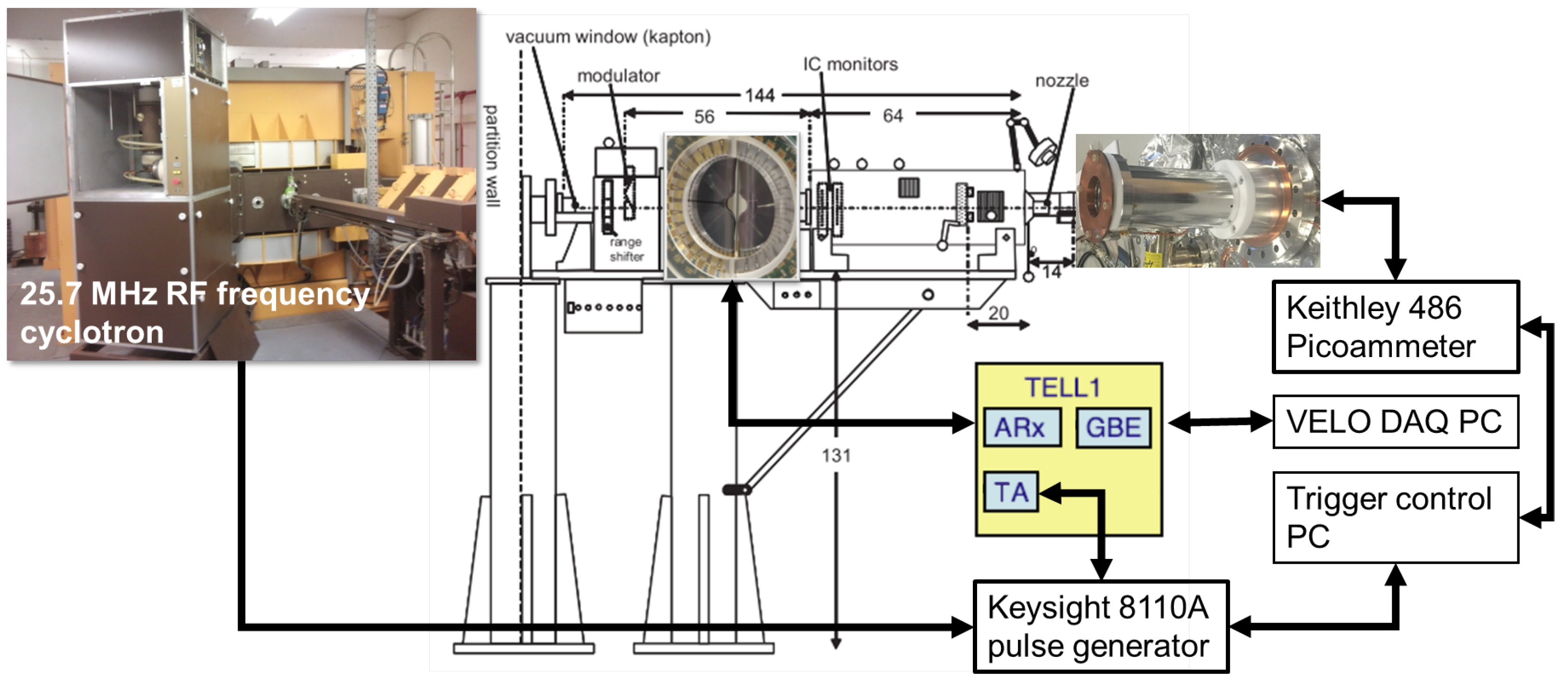
3.1. Adaptations for a Clinical Environment
In contrast to the experiments in the LHC, in a clinical environment, the VELO modules will be operated in air and the liquid CO
2 cooling had to be replaced. The newly chosen cooling system had to handle a waste heat load of 27.5 W per sensor and achieve the required operational temperature below 0 °C to minimise noise. Heat transfer simulations are performed in [
16], leading to the selection of the high cooling capacity K3 chiller, Applied Thermal Control Ltd., Whitwick, UK, of 3200 W, which operates with low viscosity HYCOOL cooling liquid to achieve the required temperature. A special case surrounding the VELO modules was machined (see
Figure 1b) for efficient cooling with dry air in a quasi-laminar flow. The dry air creates efficient isolation from the ambient air to maintain the surface of the sensors free of condensation. The air is supplied at 4–4.5 bars with an air flow of 65 l/s and a dew point of up to −70 °C through dry air inlets on each side of the case (see
Figure 1b) by the Ekom DK50 2V-S/M air compressor, Chromalytic Ltd, Fareham, UK and Ekom Nano DL030 dryer. The temperature of the modules is monitored by four EMT 1900 LCD thermometers, Lascar, Whiteparish, UK. The chiller keeps the coolant at a steady temperature of −28 °C and the thermometers record a module temperature of −5 °C during continuous operation at full power of the readout chips.
A dedicated positioning system was designed with three KR20/KR26 translational slides, THK UK GmbH, Brierley Hill, UK, with individually controlled 17HS-240E stepper motors, Mclennan Servo Supplies Ltd., Ash Vale, UK, embedded in a rigid aluminium framed stand with height adjustable feet. The guaranteed precision by the manufacturer of the motors and stages allows a positioning with an accuracy of 10 μm. The available stroke is up to 94 mm in the x-axis and 165 mm in the z-axis. For the positioning of the modules and the control of the motors, a LabVIEW remote user control interface was written.
The frame of the VELO modules is placed on a metal bottom base plate for a level and secure stand (see
Figure 3). For the alignment of the VELO sensors with the beam axis, two cross-shaped stainless steel targets were designed [
16]. A diode laser HLM1230 was embedded in a hosting aluminium boss, allowing the alignment of the detector in the beam axis with the iso-center at the end of the treatment beamline. The principle is demonstrated in
Figure 3, showing the alignment of the detector with an accuracy of 1 mm concentrically with the beam z-axis.
Long cables used in the LHC tunnels and beam pipe to connect the different parts were replaced with shorter cables. They are required to establish a new set of calibration values in clock cycles to avoid non-synchronised sampling of the TELL1 board (see
Figure 4). For the high voltage supply for the four sensors, a floating ground high voltage source-measurement unit (SMU) type EHS 82 05P-F-XXX, ISEG, Radeberg, Germany, was used to supply a bias voltage of up to −500 V. The low voltage was supplied by two pairs of bench-top power supplies: for module one, IPS 3303 and IPS 1820D, ISO-TECH, Corby, UK; and, for module two, ISO-TECH 2023 and Digimess SM5020, Digimess Instruments Ltd., Derby, UK. The latter is used to power the Beetle chips with 3.3 V, whereas the former powers the repeater board driver cards with ±6 V.
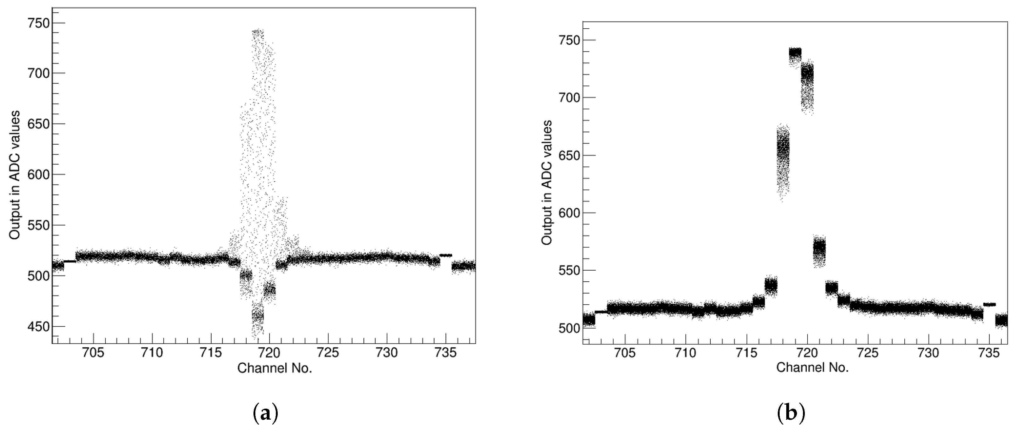
3.2. Synchronism of the Readout for Arbitrary Clocked Systems
Due to the absence of the Timing and Fast Control system and the ODIN readout supervisor, multiple changes had to be introduced for synchronised data acquisition and readout. Firstly, instead of ODIN, I
2C readout trigger commands are sent out by small EDA-00978-V1 trigger adapter mezzanine plates that were implemented on each of the four TELL1 boards. Secondly, the absence of the TFC system that synchronises the LHC particle bunch arrival frequency
with the readout chips of the sensor had to be circumvented [
17]. The clocks of the TELL1 boards and Beetle chips cannot be changed directly, since non-interchangeable quartz crystal oscillators are used to generate the internal frequency. Furthermore, a different frequency of the CCC cyclotron cannot be injected directly. However, the TELL1 boards can be synchronised with another clocked system (not 40 MHz) using the external readout trigger input accepting 3.3 V TTL signals with rising edge detection (see
Figure 5). Following a firmware update of the TELL1 boards, the rising edge of the trigger is detected with a newly introduced 120 MHz clock in phase with the 40 MHz TELL1 clock. The trigger is accepted if the rising edge of the external trigger is within the first 0–8.3 ns (120 MHz) of the 40 MHz clock and rejects all triggers which fall outside the 8.3 ns window (see
Figure 5: readout decision). Therefore, an external trigger of up to 10 kHz will be injected into the TELL1 with the 8110A pulse generator, Keysight, Santa Rosa, USA. The pulse generator will be triggered by the sinusoidal cyclotron RF frequency and thus is in phase with the readout trigger. To compensate delays through cables and hardware and to readout the maximum signal, a coarse delay of 25 ns in the configuration of the TELL1 or a fine delay of 5 ns by the pulse generator can be introduced.
To test the implemented change, a pulsed infra-red Laser Diode (LD-1060), Fermionics Lasertech, Newbury Park, USA, with a peak wavelength of 1060 nm was used to mimic the cyclotron. In
Figure 6, the comparison between non-synchronised readout and synchronised readout with the laser and one VELO R-sensor is shown. During the non-synchronised readout the front end pulse is sampled at random points by the Beetle chips. This results in a big spread of the ADC values, as seen in
Figure 6a. The pedestals (signal response without the laser) are approximately 512 ADCs, equal to half of the available range for the data. Many points are below the pedestals, which means the output pulse is sampled at a negative point decreasing the signal quality significantly. In
Figure 6b, the ADC values per channel show a much more finite spread and are above the pedestal value, since they are sampled at the peak region of the output pulse maximising the value of the laser signal. Moreover, the integrated ADC count values with their corresponding standard deviations are shown for different Peak-to-Peak voltages from 0.8 V to 1 V of the laser (see
Table 2). To extract the signal, a noise filter (pedestal value) was applied. The synchronised readout signal in ADC counts is increased by an average of 2.86 times, whereas the average standard deviation for the non-synchronised readout is 5.9% and therefore almost 20 times worse than the average standard deviation of 0.3% for the synchronised readout.
3.3. LHCb VELO Modules as a Standalone System
During the planned measurements in CCC, the VELO sensor will measure the beam current and monitor the beam profiles. The output of the VELO sensor in ADCs will be correlated and calibrated with a locally-built Faraday Cup. The Faraday Cup, optimised for the measurement of the 60 MeV treatment beam, consists of a stainless steel DN100CF four-way reducer vacuum vessel and aluminium beam stopper [
16]. To reduce size and for cost effectiveness, the chosen beam collector diameter resulted in an impedance of 25 Ω causing an impedance mismatch with the 50 Ω BNC connector. To synchronise the readout between the VELO modules and the Faraday Cup, a MATLAB script will send out two simultaneous readout triggers to the previously described pulse generator and Keithley 486 picoammeter, Keithley Instruments, Cleveland, USA that measures the beam current collected by the FC. The script will act as a master trigger for the VELO modules and FC for a synchronised readout of both systems. The overview of the complete synchronised readout system is shown in
Figure 7.
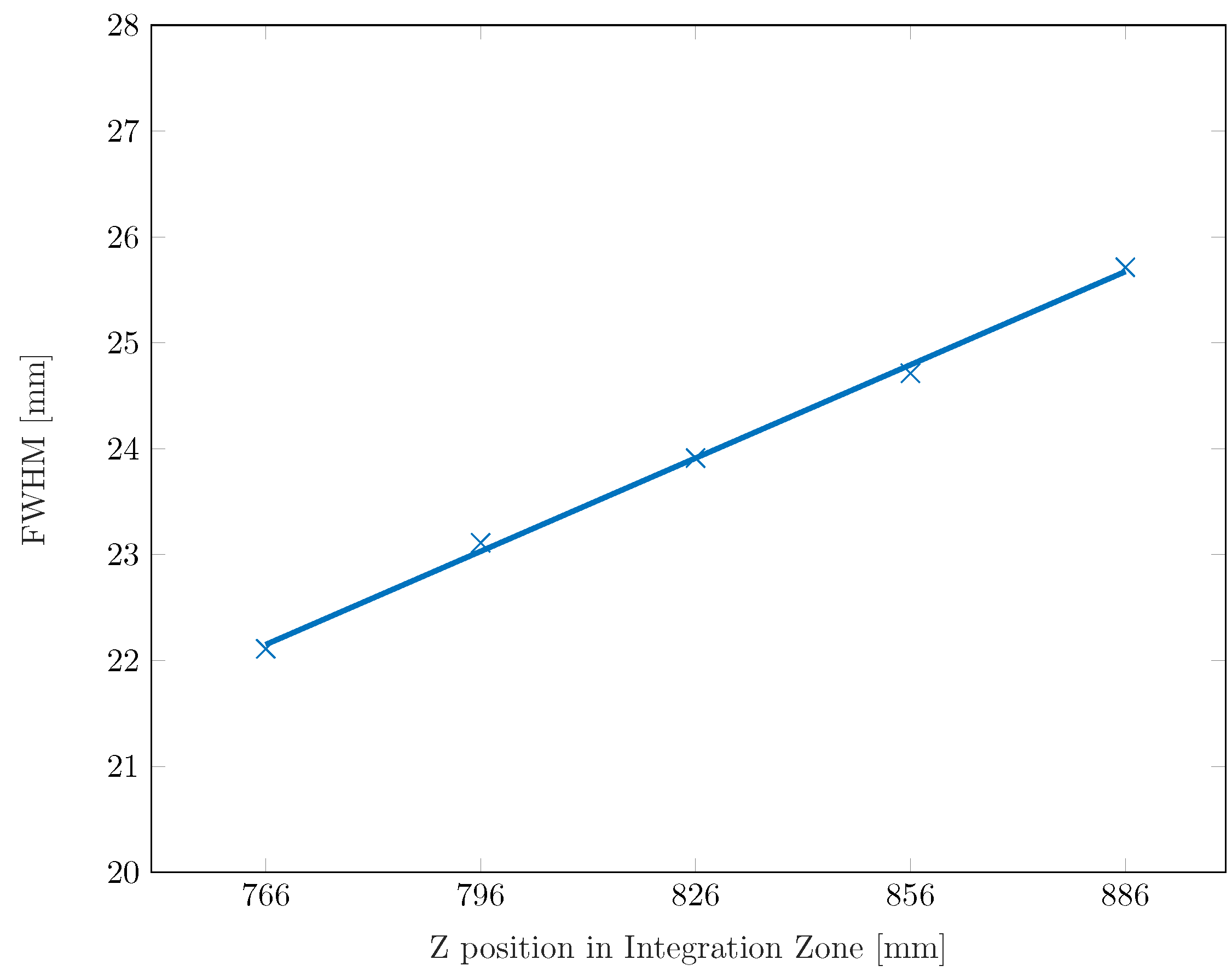
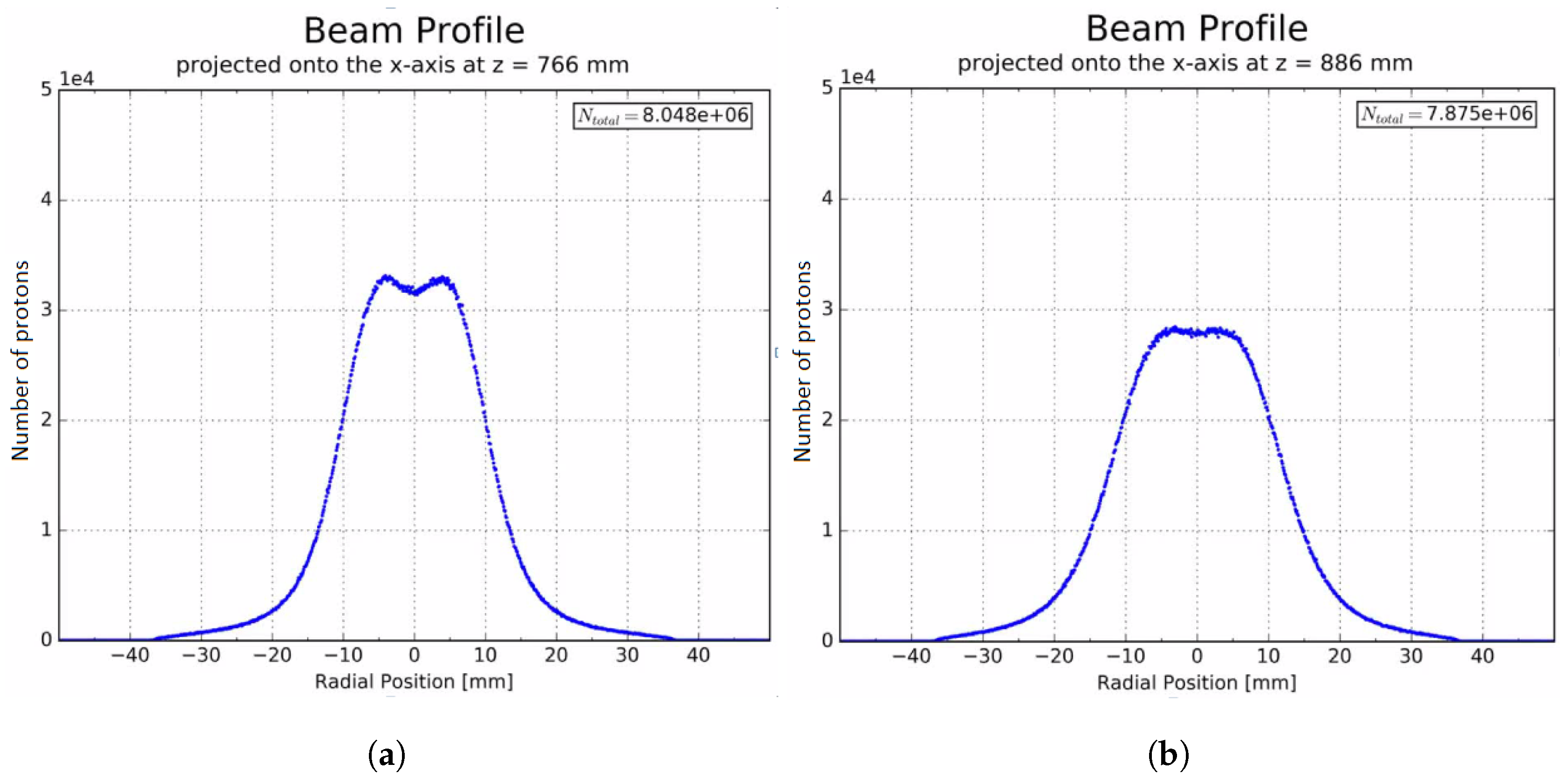
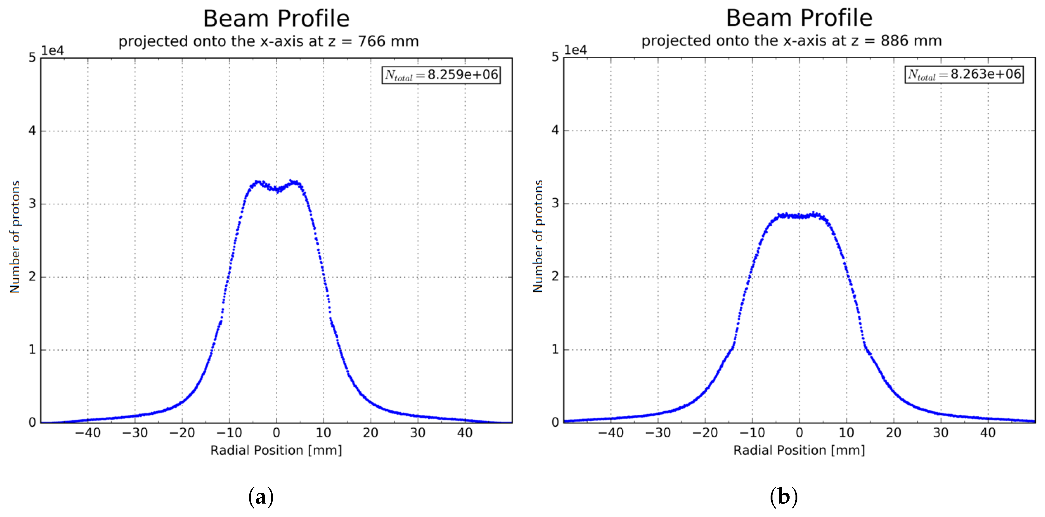
3.4. GEANT4 Beam Behaviour Studies in the Integration Zone
A first model of the complete CCC delivery system was developed by the University College London [
18] and this code was used to observe the general behaviour of the beam and halo propagation throughout the treatment beamline. Within the designated area for implementation of the VELO online beam monitor, effects of the components and interactions with the beam were also studied. Given space considerations and also to allow the sensors a non-interceptive approach to the beam, it is necessary to remove the aluminium pipe that is used in practice for visual containment of the beam. Thus, without the tube, initial results show negligible impact to the beam profile and energy spectrum thus verifying the feasibility of this integration zone. For the potential dedicated positions of the VELO modules within the integration zone, the beam divergence is shown in
Figure 8 as the FWHM. The beam diverges within the first 120 mm of the integration zone around 4 mm from the width of 22 mm to 26 mm FWHM. For position z = 766 mm and z = 886 mm, transverse beam profile plots are shown in
Figure 9, revealing a linear divergence of spread of protons from the core along the z-axis. The position of the beam z-axis here is stated as the distance from the modulator box exit (see
Figure 2).
The effects of the beam divergence and energy loss with the integration of the VELO modules as a semi-circular cut-out silicon disc were also studied. The aperture radius for the disc was chosen as 10.5 mm, which takes the surrounding case and the small gap between the two VELO module halves into account. Considering the space of the integration zone (see
Figure 2), the frame of the positioning system and the divergence of beam, the VELO modules will be positioned at a point between z = 766 mm and z = 886 mm. Two beam profiles are shown in
Figure 10 where the Si-disc is positioned at z = 766 mm and z = 886 mm. Compared to the profiles without the Si-disc, the profiles show a slightly bigger spread of a small amount of protons with the Si-disc. Moreover, the energy loss at the isocenter for different position is shown in
Table 3. The average energy loss caused by the Si-disc is 0.13 ± 0.03%.
4. Discussion
The changes for the VELO modules into a standalone system are described. An efficient venting and cooling system was designed and successfully implemented for the safe operation of the detector in air to avoid over-heating of the readout chips and to minimise noise. For the specific requirements to integrate the detector into the Clatterbridge Cancer Centre, dedicated plates and frames for a secure and stable stand of the VELO modules were machined and an alignment system was developed for precise positioning of 1 mm at iso-center. This enables movement of the VELO modules along the beamline, which can potentially mimic a second pair of modules. Additionally, the new integrated quasi online analysis software, based on a customised version of the VETRA project, will provide a hit map of the beam halo on the VELO module. Due the resolution of the strips, the alignment precision is envisaged to be reduced to 100 μm.
The needed hardware changes for the LV and HV power supply and the required cabling were carried out and the VELO modules were newly calibrated. It is notable that the communication via I2C created severe issues. The transmission of the signals via multiple hardware parts within the system surrounding the VELO modules makes the communications vulnerable. As a result, different ground potentials for the driver and receiver were created. Major efforts were undertaken to remove the ground potential by connecting the system to one common ground and by splitting up the power supply for the two modules.
The readout of the VELO modules due to the absence of the TFC and ODIN was changed and optimised. It is now possible to synchronise the proton bunch arrival with the readout of the Beetle chips. Tests comparing the non-synchronised and synchronised readout with the LD-1060 showed large improvement of the signal output and reduction of the standard error to below 1%, allowing a sensitive and accurate use of the VELO modules. As long as a feed out of the cyclotron carrying the RF frequency information exists, this method is not exclusive for the Clatterbridge Cancer Centre. The readout frequency of 10 kHz, which correlates with currently used beam monitors, is a result of the chosen output data format non-zero-suppressed, which limits the bandwidth frequency by carrying the full raw data information. By changing the data format, frequencies of up to 1.1 MHz are possible. However, this requires extensive changes in the electronics and would not be more scientifically relevant. Findings and integration of the detector within the CCC beamline were also investigated with preliminary Monte Carlo simulations using GEANT4. The integration of the VELO modules as a silicon disc showed a minimal effect of 0.13% loss on the beam energy which is clinically negligible. The lateral beam profiles show a bigger spread of the protons with the Si-disc. However, the FWHM relevant for the clinical treatment is the same. Due to the diverging beam, the position of the detector further down the integration zone results in more beam interception and therefore, the energy loss gets bigger. However, this can be easily circumvented by opening the VELO modules in the x-axis by the difference of the beam divergence. Further collaboration to develop the code will incorporate knowledge of the dynamics of the beam as transported from the cyclotron with full experimental validation for a more accurate and reliable model. This will allow benchmarking with measurements taken with the VELO modules. For the impedance mismatch of the FC, solutions were tested with a Quarter-Wavelength Transformer, but showed no result. Tests are still ongoing, such that proton bunch-by-bunch measurements will be possible [
17]. For the charge collection over a longer period, the impedance mismatch will have no effect on the planned measurements with the VELO modules.
The whole system is optimised for integration into the CCC. The capability of the VELO modules as a beam monitor will be assessed by measuring the beam current at different dose rates and by monitoring the beam profile. The clinical dose rate of the proton beam is 11 Gy/min (Private communications with Andrzej Kacperek, Clatterbridge Cancer Centre, UK). The VELO modules will interact only with a fraction of the beam and it would need more than 2000 hours of continuous beam irradiation to reach the dose levels at the LHC. The output of the VELO modules will be correlated and calibrated with the Faraday Cup and the delivery system, which detects the in-beam parameters. With this information, a halo-dose databank will be established.
Furthermore, a collaboration with Amsterdam Scientific Instruments (ASI) within the Optimization of Medical Accelerators (OMA) project [
19] facilitating involvement of the Medipix3 pixel detector is intended for complimentary particle imaging and detection measurements.
5. Conclusions
The beneficial sensor design of the LHCb VELO module with a central semi-circular aperture enables the core of the beam to potentially pass through with minor distortions to its profile or energy. The development of the VELO module as a standalone system presented major challenges along its path. All the unique features in the LHC environment were replaced and adapted, thus a full setup optimised for the implementation in the proton beamline at CCC is presented. Measurement will commence in late spring 2019 and these beam diagnostics studies aim to influence the design decision of future beamlines.
Author Contributions
R.S. carried out the research and wrote the paper; J.Y. supported the project with GEANT4 simulations and advice; H.Z. supported partly Roland’s work with technical advice; T.C. realised the venting, cooling and positioning adaptations and built the Faraday Cup; T.S. helped to resolve electronic and hardware issues of VELO modules; G.H. and O.G. advised on the VELO module hardware change possibilities and did the TELL1 board’s firmware update to introduce a new clock for synchronisation with non 40 MHz clocks; T.S. carried out software changes and updates on the VETRA software; and C.W. originated the idea and was the overall project coordinator.
Funding
This research was funded by the EU under grant agreements 215080 and 675265, as well as the Cockcroft Institute core Grant No. ST/G008248/1.
Acknowledgments
The authors would like to thank Andrzej Kacperek and his team at the CCC for their ongoing support; Karol Hennessy and Jan Buytaert for their technical expertise for the VELO module; and Simon Jolly and Matthieu Hentz for provision of resources and help with simulation modelling. We look forward to extending the studies with the North West Cancer Research Centre under Jason Parsons.
Conflicts of Interest
The authors declare no conflict of interest.
References
- Paganetti, H. Series in Medical Physics and Biomedical Engineering: Proton Therapy Physics, 1st ed.; CRC Press, Taylor and Francis Group: Boston, MA, USA, 2012; pp. 191–221. ISBN 978-1-4398-3645-3. [Google Scholar]
- Actis, O.; Meer, D.; König, S. Precise on-line position measurement for particle therapy. J. Instrum. 2014, 9, C12037. [Google Scholar] [CrossRef]
- Sadrozinski, H.W.; Ely, S.; Fadeyev, V.; Galloway, Z.; Ngo, J.; Parker, C.; Petersen, B.; Seiden, A.; Zatserklyaniy, A.; Cartiglia, N.; et al. Ultra-fast silicon detectors. Nucl. Instrum. Methods Phys. Res. 2013, 730, 226–231. [Google Scholar] [CrossRef]
- Opalka, L.; Granja, C.; Hartmann, B.; Jakubek, J.; Jaekel, O.; Martisikova, M.; Pospisil, S.; Solc, J. 3D measurement of the radiation distribution in a water phantom in a hadron therapy beam. J. Instrum. 2012, 7, C01085. [Google Scholar] [CrossRef]
- The LHCb Collaboration. The LHCb detector at LHC. J. Instrum. 2008, 3, S08005. [Google Scholar] [CrossRef]
- The LHCb Collaboration. LHCb VELO Technical Design Report; Technical Report CERN-LHCC-2001-0011; The LHCb Collaboration: Geneva, Switzerland, 2001. [Google Scholar]
- Bates, A.G.; Borel, J.; Buytaert, J.; Collins, P.; Eckstein, D.; Eklund, L.; Ferro-Luzzi, M.; Jans, E.; Kennedy, J.; Ketel, T. The LHCb VELO: Status and Upgrade Developments. IEEE Trans. Nucl. Sci. 2001, 53, 1689–1693. [Google Scholar] [CrossRef]
- Loechner, S.; Schmelling, M. The Beetle Reference Manual—Chip Version 1.3, 1.4 and 1.5; Technical Report CERN-LHCb-2005-105; The LHCb Collaboration: Geneva, Switzerland, 2006. [Google Scholar]
- Verlaat, B.; Van Lysebetten, A.; Van Beuzekom, M. CO2 cooling for the LHCb-VELO experiment at CERN. In Proceedings of the 8th IIF/IIR Gustav Lorentzen Conference on Natural Working Fluids, Copenhagen, Denmark, 7–10 September 2008. [Google Scholar]
- Haefeli, G.; Bay, A.; Legger, F.; Locatelli, L.; Christiansen, J.; Wiedner, D. Specification fro a Common Read Out Board for LHCb; Technical Report CERN-LHCb-2003-007; The LHCb Collaboration: Geneva, Switzerland, 2003. [Google Scholar]
- The LHCb Collaboration. LHCb Trigger System Technical Design Report; Technical Report CERN-LHCC-2003-031; The LHCb Collaboration: Geneva, Switzerland, 2003. [Google Scholar]
- Akiba, K. Description of the VELO Timing System and Its Configuration; Technical Report CERN-LHCb-PUB-2011-012; The LHCb Collaboration: Geneva, Switzerland, 2011. [Google Scholar]
- Jacobsson, R.; Jost, B. Timing and Fast Control; Technical Report CERN-LHCb-2001-16; The LHCb Collaboration: Geneva, Switzerland, 2001. [Google Scholar]
- Jacobsson, R. The Final LHCb Readout Supervisor “ODIN”. In Proceedings of the 8th Workshop on Electronics for LHC Experiments, Colmar, France, 9–13 September 2002. [Google Scholar]
- Kacperek, A. Protontherapy of eye tumours in the UK: A review of treatment at Clatterbridge. Appl. Radiat. Isotopes 2009, 67, 378–386. [Google Scholar] [CrossRef] [PubMed]
- Cybulski, T. A Non-Invasive Beam Current Monitor for a Medical Accelerator. Ph.D. Thesis, University of Liverpool, Liverpool, UK, 2017. [Google Scholar]
- Schnuerer, R.; Girard, O.; Haefeli, G.; Welsch, C.; Yap, J.; Zhang, H. Implementation of a Non-invasive Online Beam Monitor at a 60 MeV Proton Therapy Beamline. In Proceedings of the 9th International Particle Accelerator Conference, Vancouver, BC, Canada, 29 April–4 May 2018. [Google Scholar] [CrossRef]
- Clatterbridge Simulation Model. Available online: http://www.hep.ucl.ac.uk/pbt/wiki/Clatterbridge (accessed on 17 December 2018).
- Optimization of Medical Accelerators Project. Available online: https://www.oma-project.eu (accessed on 11 September 2018).
© 2018 by the authors. Licensee MDPI, Basel, Switzerland. This article is an open access article distributed under the terms and conditions of the Creative Commons Attribution (CC BY) license (http://creativecommons.org/licenses/by/4.0/).