Article

C-2p Spin-Polarizations along with Two Mechanisms in Extended Carbon Multilayers: Insight from First Principles

1
Lebanese German University, Sahel-Alma, Jounieh P.O.BOX 206, Lebanon
2
Formerly at University of Bordeaux, ICMCB–CNRS, 33600 Pessac, France
Condens. Matter 2020, 5(3), 48; https://doi.org/10.3390/condmat5030048
Submission received: 8 June 2020 / Revised: 16 July 2020 / Accepted: 17 July 2020 / Published: 22 July 2020

Abstract

:
From density functional theory investigations helped with crystal chemistry rationale, single-atom C, embedded in layered hexagonal CC’n (n = 6, 12 and 18) networks, is stable in a magnetic state with M(C) = 2 μB. The examined compositions, all inscribed within the P6/mmm space group are characterized as increasingly cohesive with n, figuring mono-, bi- and tri-layered honeycomb-like C’6 networks respectively. The spin projected total density of states shows a closely half-metallic behavior with a gap at minority spins (↓) and metallic majority spins (↑). Such results together with the large C-C intersite separation and the integer 2 μB magnetization, let us propose an intra-band mechanism of magnetic moment onset on carbon 2p states. Support is provided from complementary calculations assuming a C2C’12 structure with planar 2C with d(C-C) = 2.46 Å resulting into a lowering of the magnetization down to the 0.985 μB/C atom and a ferromagnetic order arising from interband spin polarization on C where one nonbonding spin polarizes whereas the other is involved with the bonding with the other carbon. Illustration of proofs is provided with the magnetic charge density projected onto the different atoms, showing its prevalence around C, contrary to the C’n (C’6 layers), as well as electron localization function ELF.

Graphical Abstract

1. Introduction and Context

Unpaired electrons in outer shells of atoms let identify a paramagnetic behavior with no parallel alignment of spins. This is opposed to diamagnetic atoms where all electrons are paired such as in magnesium with Mg(3s2). Carbon, as an isolated element is paramagnetic C(2s2, 2p2) with 2 unpaired p-electrons. In fact, such a configuration is seldom encountered in chemical systems, because carbon and its neighbors combine through pairing their respective electrons to form bonds. In paramagnetic elements, a lowering of the energy occurs when the electron spins become parallel (↑,↑) and in certain cases, below a critical temperature called the Curie temperature TC, an ordering of the spins occurs adding them up constructively and leading to a long-range ferromagnetic state. Regarding the highest occupied valence states of the 1st-period transition metals, three ferromagnetic metals are found: Fe(4s2, 3d6) with M = 2.2 μB, Co(4s2, 3d7) with M = 1.7 μB and Ni(4s2, 3d8) with M = 0.6 μB; all of them having unpaired d electrons and behaving as paramagnets above TC. A close inspection is obtained from band structure calculations considering firstly a non-spin-polarized state (NSP). The d states show a significant localization illustrated by a high density of states (DOS) at the Fermi level EF: n(EF), signaling the instability of such a spin degenerate configuration [1]. Upon carrying out further spin-polarized SP calculations accounting for two spin channels (majority spins ↑, and minority spins ↓), magnetic moments develop on the atoms. The designation of ‘majority’ and ‘minority’ arises from the fact that the former has a larger electron population because it is energy down-shifted oppositely to the minority spins DOS, which are energy up-shifted (cf. Figure 4). Such properties are quantified from the quantum density functional theory DFT [2,3]. In the 2nd and 3rd transition metal periods, the broadening of the 4d-and 5d bands hinders localization of the d states and hence the onset of magnetic polarization; but under certain crystal structure conditions, a narrowing of the bands may occur such as for the 3rd period iridium in a structure characterized by isolated IrO6 octahedra within CaII4IrIVO6 and M(Ir)= 0.5 μB [4].
Then, in the 1st period ferromagnetic metals, the magnetic moment is of inter-band nature, meaning that it is mediated by the electron gas (s-like), i.e., in a “d…s…d”-like bridging and the magnetic moments are not integers as shown above. To some extent, uranium presents an intermediate situation where U 5f band, less narrow than rare-earth 4f one, behaves like a transition metal’s d band [5].
Another kind of magnetism occurs for rare-earth gadolinium metal, characterized by half-filled 4f shell, i.e., with seven electrons, which all polarize to provide a high magnetic moment of 7 μB. Gd is a ferromagnet with TC close to room temperature. Here, oppositely to Fe, Co and Ni, the magnetic polarization is of intra-(4f)band nature, i.e., without calling for the mediation of itinerant s electrons. The underlying effect is that 4f states are localized in a narrow band in the atomic state and they keep this behavior in the periodic organized solid.
Consequently, the elements with outer shells having unsaturated occupations as nd and 4f (above examples) are likely to lead to inter- and intraband spin polarization respectively, provided the conditions of sufficient band localization be met in the crystal environment.
Note that regarding p-elements magnetism, ordered magnetic moments were identified in hexaborides AEB6 (AE = Ca, Sr) [6] as well as in CdS doped with the main group elements [7].
Focusing on carbon herein, one is presented with two possible situations regarding the onset of magnetization through:
  • Keeping an isolated atomic behavior—as for Gd (4f)—characterized by two unpaired carbon p electrons in an appropriate crystal–chemical host, and leading eventually to their polarization and the expectation of M(C) = 2 μB. We assess this within an intraband spin polarization mechanism;
  • Checking for the hypothesis of interband spin polarization mechanism by involving two carbon neighbors at a distance which allows electronic interactions between them. The subsequent bonding involves a spin pairing and a loss of the magnetization magnitude. The expectation is a magnitude of M(C) close to 1 μB.
Along with these two hypotheses, and based on the DFT calculation of energies and magnetic configurations, the paper presents results and assessments of the two mechanisms in new carbon-based model multilayered systems. While the present investigation is of theoretical scope, feasibility aspects find support from experimental preparation of multilayered graphene/graphite sheets [8].

2. Brief Presentation of the Computational Methodology

Within the DFT, the optimization of the candidate structures (the atomic positions and the lattice parameters) is needed in the first place to identify the minimum energy configuration. The plane wave Vienna ab initio simulation package (VASP) package [9,10] was used with its implementation of the projector augmented wave (PAW) method [10,11]. The DFT exchange-correlation effects were accounted for with the generalized gradient approximation (GGA) scheme [12]. A conjugate-gradient algorithm [13] was used to relax the atom positions of the different compositions into the ground-state structure. Structural parameters were considered as fully minimized when forces on the atoms were less than 0.02 eV/Å and the stress components were below 0.003 eV/Å. A tetrahedron method [14] was applied for geometry relaxation and total energy calculations. The integrals within the reciprocal space (Brillouin zone BZ) were approximated using a special k-point sampling [15]. The calculations were converged at an energy cut-off of 400 eV for all compounds. The k-mesh integration was carried out with increasing BZ precision over successive calculations for best convergence and relaxation to zero strains. Calculations were systematically carried out considering both non-spin-polarized (NSP) and spin-polarized (SP)–magnetic configurations.
Properties related with electron localization are obtained from real space analysis of electron localization function (ELF) according to Becke and Edgecomb [16] as initially devised for Hartree–Fock calculations then adapted to DFT methods as based on the kinetic energy in which the Pauli exclusion principle is included by Savin et al. [17]: ELF = (1 + χσ²)−1 with 0 ≤ ELF ≤ 1, i.e., ELF is a normalized function. In this expression the ratio χσ = Dσ/Dσ0, where Dσ = τσ − ¼(∇ρσ)²/ρσ and Dσ0 = 3/5 (6π²)2/3ρσ5/3 correspond respectively to a measure of Pauli repulsion (Dσ) of the actual system and to the free electron gas repulsion (Dσ0) and τσ is the kinetic energy density. ELF is a normalized function with 0 ≤ ELF ≤ 1, ranging from 0 for no localization to 1 for full localization; magnitudes 1/2 correspond to free-electron like localization.

3. Results and Discussion

3.1. Geometry Optimization and Energy-Dependent Results

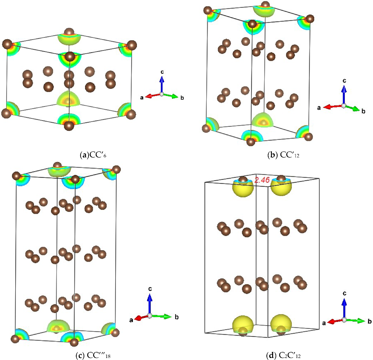
3.1.1. CC’n (n = 6, 12 and 18)
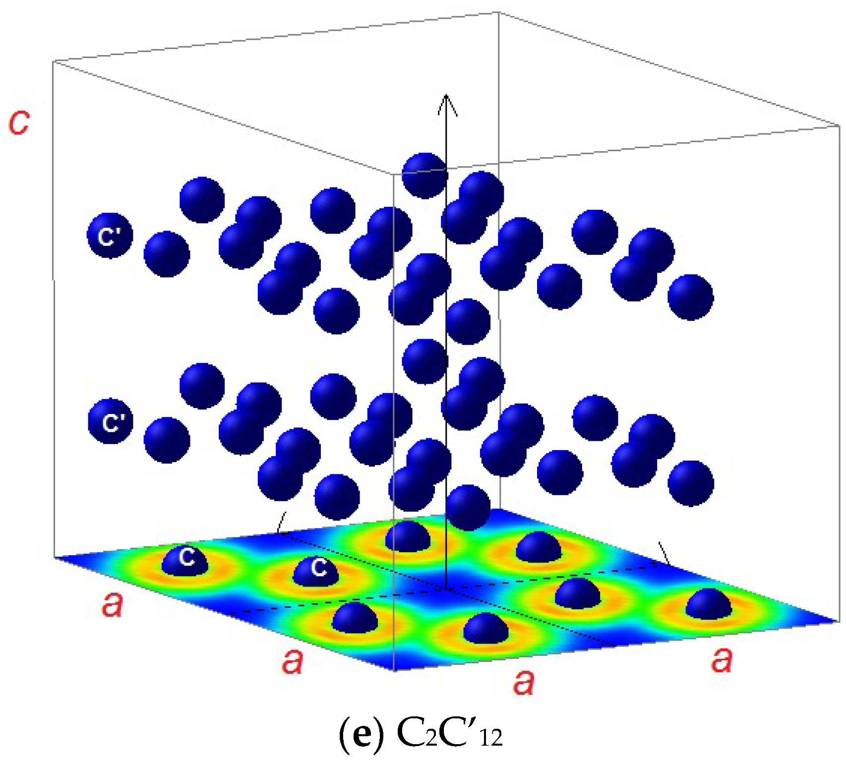
Honeycomb carbon networks were identified in the lithium graphitic anode materials LiC6 and LiC12 [18] with the P6/mmm space group. Full geometry relaxations were carried out assuming NSP and SP configurations. The results are given in Table 1b. The respective structures transposed to CC’6 and CC’12 are shown in Figure 1a,b. In both compounds, the SP configuration has lower energy than the NSP and the cohesive energies obtained from subtracting the atomic C contributions are negative with the same trends of larger stability of SP. Comparing CC’6 to CC’12, the latter exhibits a larger cohesive energy letting propose that two C’6 layered compounds are more favorable. One can also note that the magnetization of M = 2 μB remains the same in the two compounds, due to the full polarization of carbon two p electrons. Regarding the crystal parameters, the onset of spin polarization causes a large increase of the hexagonal c/a ratio while few changes can be observed for the hexagonal a lattice constant as well as the C’ positions, which are mainly determined by the rigid C’6 network. In both stoichiometries, d(C’-C’) changes little, with 1.4 Å and almost unchanged by the spin state. Such trends and observations needed to be further confirmed with a structure comprising three C’6 layers with the formulation CC’”18, with C at the origin and the layers at C’ and C”. The obtained structure within the same space group is shown in Figure 1c and the geometry optimized parameters and energies explicated in Table 1(c). Indeed the trend of stabilization through multilayered stoichiometry is confirmed with similar trends of lattice parameters and an increase of hexagonal c/a ratio always larger in SP than with the increase of the Ecoh. magnitude to −1.69 eV, i.e., versus Ecoh. (CC’12) = −1.518 eV and Ecoh. (CC’6) = −1.021 eV (SP values, per C atom). Additionally, the SP configuration is more cohesive than NSP and the magnitude of the magnetic moment on C is 1.98 μB, close to the saturation moment of 2 μB.
A most relevant result from the calculations is the integer 2 μB magnitude of corner C in all structures. The C-C separation is large and amounts to the a lattice constant magnitude, which is systematically larger than 4 Å, suggesting an isolated character and a development of onsite magnetic moment through intraband spin polarization.

3.1.2. C2C’12

Support of the above hypothesis was needed with a structure accounting for two neighboring carbon atoms that would magnetically polarize through an inter-band mechanism.
Figure 1d shows C2C’12 structure based on the P6/mmm space group and where C belongs to a two-fold Wyckoff position, i.e., at 1/3, 2/3, 1/2 and 2/3, 1/3, 1/2. After full geometry relaxation, the C-C distance was 2.46 Å. The results show SP as the ground state with, however, a cohesive energy of −1.22 eV/at, smaller than the cohesive energy of CC’12 of −1.518 eV. The remarkable result is now the lowering of the magnitude of magnetization, which amounts to 1.97 μB for the two carbon atoms, i.e., 0.985 μB/C atom. The long-range magnetic order is ferromagnetic. Further antiferromagnetic calculations imposing two magnetic substructures, one labeled as SPIN UP and the other as SPIN-DOWN, i.e., C↑…C↓ as well as all the C’ atoms. At self-consistent convergence, a raise of the energy was noted and the system becomes less cohesive.
One can then assume that the loss of magnetization magnitude is due to spin pairing through the bonding between the two carbon atoms, leaving one nonbonding spin polarizing along the c hexagonal direction. The mechanism of spin polarization is then suggested to be of an interband nature.

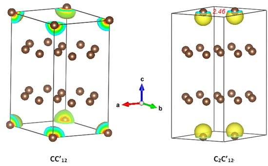
3.2. Magnetic Charge Density

The above results need to be supported by the magnetic charge densities on the different atomic constituents on one hand and with a projection of the electron localization on the other hand.
The magnetic charge density corresponds to the density difference between majority spins (↑) and minority spins (↓). Figure 1 shows the magnetic charge density around the atoms with the rainbow colored spheres. One can see in Figure 1b,d the difference occurring for nearest neighboring two successive Fe’s, i.e., with d(Fe-Fe) = a lattice constant in CC’6 (Figure 1b), which amounted to more than 4 Å. Oppositely, in C2C’12 (Figure 1d), the in-plane two neighboring Fe were at a 2.46 Å smaller separation. For the C’ and C” atoms belonging to the C’6 layers, there were no magnetic charge densities around them since the difference of population ↑-↓ is zero. While this is expected, it is interesting to note the difference of shapes between the spheric-like volume for the isolated C in Figure 1 a–c versus the elongated shape along with the c direction in Figure 1d.

3.3. Electron Localization Function ELF

The ELF are shown in Figure 2. The color scheme is as follows: blue for ELF = 0 (no localization); red color for full localization with ELF = 1 and green color for ELF = 1/2, corresponding to a free electron-like behavior. Firstly in Figure 2a we show the ELF of a C’ layer in 2 × 2 × 1 projection where the red zones of strong localization allow depicting the C’6 (C”6) rings forming such layers. There are no blue zones pointing to no electron localization and the layer is similar to a graphitic one letting it suggest a semi-conducting like behavior for the layer. Focusing on the basal planes, Figure 2b–d exhibits blue zones of no localization between the C sites thus supporting their isolated character electronically and magnetically, with d(C-C)~ahex. Oppositely, in Figure 2e relevant to C2C’12, the two C atoms are in the basal plane at a distance of 2.46 Å and there is a significant green zone of free electron-like character between the two atoms. Then the ELF projections provide further illustration of the different magnetic behaviors observed, i.e., intraband versus interband magnetic polarizations.

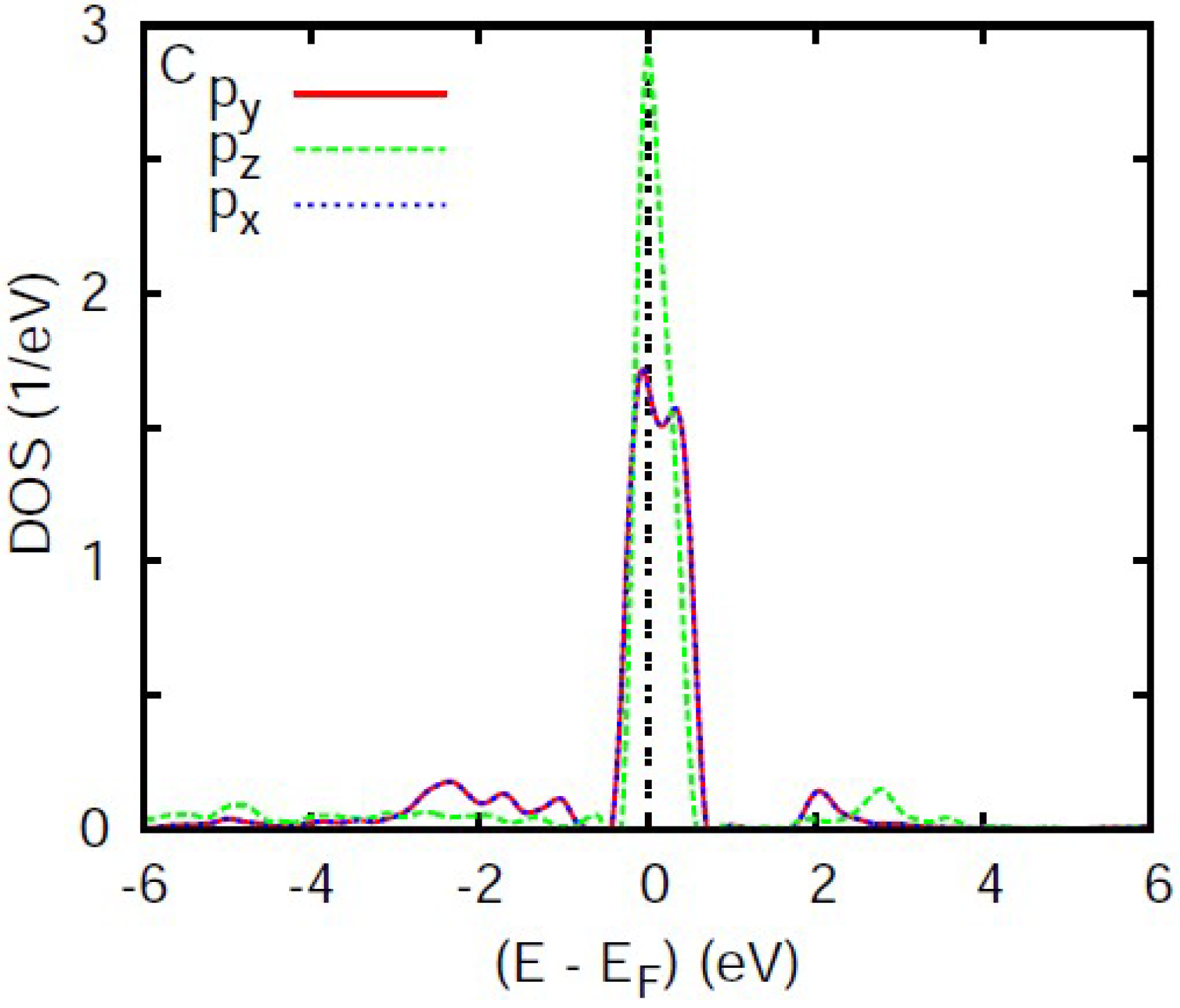
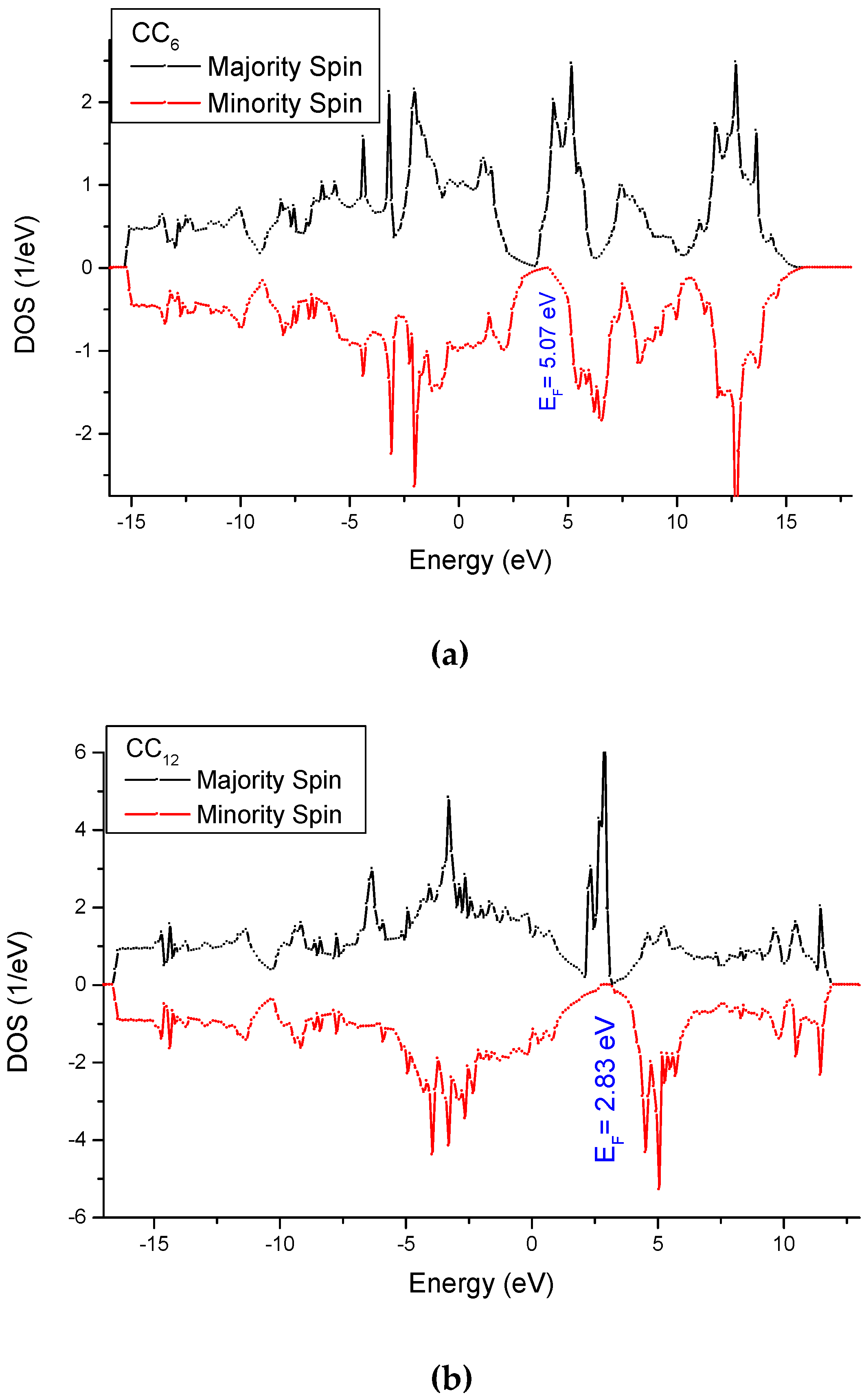
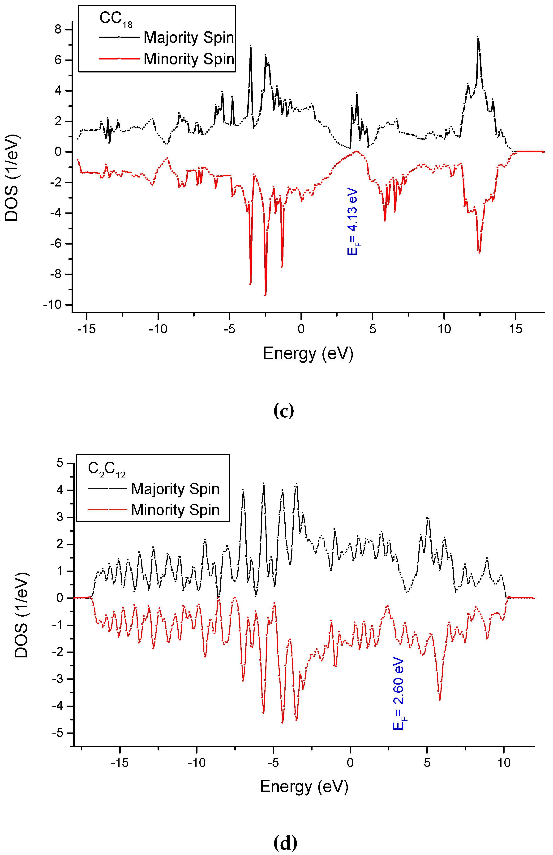
3.4. Analysis of the Electronic Density of States

Considering non-spin-polarized configurations (NSPs), Figure 3 shows the orbital projected DOS of C typically observed in the CC’n stoichiometries. There are two kinds of partial DOS: an intense sharp peak and a slightly broader one, both centered on the Fermi level (zero of energy along the x-axis). In the P6/mmm space group, the corresponding point group is D6h, which leads to the observed split in two manifolds A1u and E2u for pz and px,y respectively. The high DOS at EF is a signal of instability in such spin degenerate configuration.
From the subsequent SP calculations, the total DOS were plotted for majority spins (↑) and minority spins (↓) in Figure 4. The difference between the two populations provides a magnetic moment. The energy position of the Fermi level is indicated and shown to be at a minimum of minority spins n(EF ↓) observed for all three CC’n stoichiometries, whence the integer 2 μB/C atom and the half-metallic ferromagnet character.
Different features appear for the last panel corresponding to the C2C’12 SP DOS, which show less energy shift difference between the two spin DOS and broader and less shaped DOS. Additionally, one can notice the absence of a trough at EF for either n(EF) ↑ or ↓ with and a rather metallic-like character. These results are further illustrations of the intraband magnetism on C with an integer moment of 2 μB v/s interband magnetism, with a non-integer moment on carbon lower than 1 μB. The first mechanism being illustrated by the half-metallic ferromagnetic behavior of the SP-DOS, with a deep minimum as shown in Figure 4b for the minority spins (↓) at EF; oppositely to the continuing, non-interrupted DOS in both spin channels, ↑ and ↓ with no trough at EF (Figure 4d).

4. Conclusions

We have shown that magnetically polarized carbon was increasingly stabilized upon considering hosting multilayer new CC’n (n = 6, 12 and 18) stoichiometries within the hexagonal P6/mmm space group. The occurrence for C of a particular mechanism for the onset of magnetization was highlighted and identified as being of an intra-band type featuring an integer magnetization of 2 μB due to the large separation between nearest neighbor atoms. Considering further a stoichiometry with 2 C closer neighbors in model C2C’12, an interband spin polarization mechanism was identified and illustrated with an electron localization projection showing a free electron-like localization between the two atoms. The magnetization drops then to less than 1 μB /at. due to the pairing of one spin to ensure for the interaction between the two in-plane carbon atoms. It is worth mentioning at this point that the layered-like host structures proposed herein are unique in supporting magnetic polarizations (inter- and intra-); that is, with respect to LaNi5-type or AlB2-type, both known in the P6/mmm N°191 space group, but presenting less extended networks.
While further investigations are needed to clearly identify the magnitude of the Curie order temperature knowing the DFT calculations are zero-temperature, efforts for preparing such multilayer new stoichiometries in view [8]. Our results are also supported by recently identified observation of critical magnetic behavior in 2D carbon based composites by Shukla [19].

Funding

This research received no external funding.

Acknowledgments

We used VESTA software for the structure and charge density sketches [20]. Computations were carried out on Xeon workstations of C2M2S (Computer Center for Materials and Molecular Sciences) of the Lebanese German University.

Conflicts of Interest

The author declares no conflict of interest.

References

  1. Mohn, P. Magnetism in the Solid State—An Introduction; Springer Series in Solid-State Sciences; Springer: Heidelberg, Germany, 2003. [Google Scholar]
  2. Hohenberg, P.; Kohn, W. Inhomogeneous Electron Gas. Phys. Rev. 1964, 136, B864–B871. [Google Scholar] [CrossRef] [Green Version]
  3. Kohn, W.; Sham, L.J. Self-Consistent Equations Including Exchange and Correlation Effects. Phys. Rev. 1965, 140, A1133–A1138. [Google Scholar] [CrossRef] [Green Version]
  4. Matar, S.F.; Etourneau, J. (CaO)nIrO2 (n = 1, 2, 4) family: Chemical scissors effects of CaO on structural characteristics correlated to physical properties. Ab initio study. J. Solid State Chem. 2017, 255, 82–88. [Google Scholar] [CrossRef]
  5. Matar, S.F.; Eyert, V.; Mavromaras, A.; Najm, S.; Chevalier, B.; Etourneau, J. Chemical bonding and magnetism in the ternary germanides UT2Ge2 (T = 3d transition metal) from local spin density functional calculations. J. Magn. Magn. Mater. 1997, 174, 219–235. [Google Scholar] [CrossRef]
  6. Dorneles, L.S.; Venkatesan, M.; Moliner, M.; Lunney, J.G.; Coey, J.M.D. Magnetism in thin films of CaB6 and SrB6. Appl. Phys. Lett. 2004, 85, 6377–6379. [Google Scholar] [CrossRef]
  7. Bedolla, P.O.; Gruber, C.; Mohn, P.; Redinger, J. p-electron magnetism in CdS doped with main group elements p-electron magnetism in CdS doped with main group elements. J. Phys. Condens. Matter. 2012, 24, 476002–476005. [Google Scholar] [CrossRef] [PubMed]
  8. Tatami, A.; Tachibana, M.; Yagi, T.; Murakami, M. Preparation of multilayer graphene sheets and their applications for particle accelerators. AIP Conf. Proc. 2018, 1962, 030005. [Google Scholar] [CrossRef]
  9. Kresse, G.; Furthmüller, J. Efficiency of ab-initio total-energy calculations for metals and semiconductors using a plane-wave basis set. Phys. Rev. B Condens. Matter Mater. Phys. 1996, 54, 11169–11186. [Google Scholar] [CrossRef] [PubMed]
  10. Kresse, G.; Joubert, J. From ultrasoft pseudopotentials to the projector augmented wave. Phys. Rev. B Condens. Matter Mater. Phys. 1999, 59, 1758–1775. [Google Scholar] [CrossRef]
  11. Blöchl, P.E. The projected augmented wave method. Phys. Rev. B Condens. Matter Mater. Phys. 1994, 50, 17953–17979. [Google Scholar] [CrossRef] [PubMed] [Green Version]
  12. Perdew, J.; Burke, K.; Ernzerhof, M. The Generalized Gradient Approximation Made Simple. Phys. Rev. Lett. 1996, 77, 3865–3868. [Google Scholar] [CrossRef] [PubMed] [Green Version]
  13. Press, W.H.; Flannery, B.P.; Teukolsky, S.A.; Vetterling, W.T. Numerical Recipes; Cambridge University Press: New York, NY, USA, 1986. [Google Scholar]
  14. Blöchl, P.E.; Jepsen, O.; Anderson, O.K. Improved tetrahedron method for Brillouin-zone integrations. Phys. Rev. B 1994, 49, 16223. [Google Scholar] [CrossRef] [PubMed]
  15. Monkhorst, H.J.; Pack, J.D. Special k-points for Brillouin Zone integration. Phys. Rev. B 1976, 13, 5188. [Google Scholar] [CrossRef]
  16. Becke, D.; Edgecombe, K.E. A simple measure of electron localization. J. Chem. Phys. 1990, 92, 5397–5401. [Google Scholar] [CrossRef]
  17. Savin, A.; Jepsen, O.; Flad, J.; Andersen, K.O.; Preuss, H.; von Schnering, H.G. The ELF perspective of chemical bonding. Angew. Chem. Int. Ed. Engl. 1992, 31, 187–191. [Google Scholar] [CrossRef]
  18. Dolotko, O.; Senyshyn, A.; Mühlbauer, M.J.; Nikolowski, K.; Ehrenberg, H. Understanding structural changes in NMC Li-ion cells by in situ neutron diffraction. J. Power Sources 2014, 255, 197–200. [Google Scholar] [CrossRef]
  19. Shukla, V. Observation of critical magnetic behavior in 2D carbon based composites. Nanoscale Adv. 2020, 2, 962. [Google Scholar] [CrossRef] [Green Version]
  20. Momma, K.; Izumi, F. VESTA 3 for three-dimensional visualization of crystal, volumetric and morphology data. J. Appl. Crystallogr. 2001, 44, 1272. [Google Scholar] [CrossRef]
Figure 1. (ac) Sketches of the crystal structures of mono, bi- and tri-layered chemical systems. Carbon atoms at the corners are represented with magnetic charge density exhibited by the colored envelops, specifically showing that magnetic polarization occurs only on them with M = 2 μB. (d) C2C’12 structure showing the prevailing interband spin polarization with a lowering to 1 μB per carbon due to the presence of two C neighbors characterized by significant charge localization between them with an itinerant character from ELF at Figure 2e.
Condensedmatter 05 00048 g001
Figure 2. Electron localization function (ELF) with a 2 × 2 × 1 projection. (a) C’6 plane; (bd) ELF slices crossing the basal plane containing C and (e) ELF crossing the plane containing two adjacent C atoms. Notice the free electron-like behavior (green) between the C atoms stressing the inter-band spin-polarization mechanism in C2C’12 (e).
Condensedmatter 05 00048 g002aCondensedmatter 05 00048 g002b
Figure 3. Density of states (DOS) of the three carbon p orbitals in non-spin-polarized configuration (NSP) calculations of CC’n. The splitting in D6h point group of P6/mmm space group leads to two manifolds of C-2p: A1u and E2u for pz and px,y resp. The high DOS at EF is a signal of instability in such a spin degenerate configuration.
Condensedmatter 05 00048 g003
Figure 4. Spin projected total DOS of the CC’n (n = 6, 12 and 18) and C2C’12 stoichiometries. (a) CC’6, (b) CC’12, (c) CC’18, (d) C2C’12.
Condensedmatter 05 00048 g004aCondensedmatter 05 00048 g004b
Table 1. Calculated results for lattice parameters with distances given in Å and energies in eV. Space group P6/mmm N°191. In the three CC’n crystal structures, C is at (1a) (0,0,0) and in C2C’12, C at (2c) 1/3, 2/3, 0 (cf. Figure 1). Atomic energy: EC = −7.11 eV.
(a). CC’6.
Magn. Config.NSPSP
a 4.2854.272
c/a0.9331.183
d(C’-C’)1.41–1.431.42-1.43
C’(6k) x, 0, ½0.3350.333
Tot. Energy 56.23−56.91
Ecoh. /at.−0.932−1.021
M (μB)-2.01
(b). CC’12.
Magn. Config.NSPSP
a4.2784.265
c/a1.8202.060
d(C’-C’)1.42–1.431.42–1.43
C’(12n) x, 0, z0.334/0.2800.333/0.297
Tot. Energy111.46−112.16
Ecoh. /at.−1.464−1.518
M (μB)-2.01
(c). CC”’18 (CC’12C”6).
Magn. Config.NSPSP
a4.2754.265
c/a2.572.68
d(C’-C’)(C”-C”)1.41–1.421.41–1.42
C’(12n) x, 0, z0.334/0.1830.333/0.196
C”(6k) x, 0, ½0.3330.334
Tot. Energy166.57−167.22
Ecoh. /at.−1.657−1.691
M (μB)-1.980
(d). C2C’12.
Magn. Config.NSPSP
a 4.2204.230
c/a2.2382.458
d(C’-C’)1.411.41
C’(12n) x, 0, z0.333/0.3190.333/0.308
Tot. Energy116.46−116.60
Ecoh. /at.−1.20−1.22
M (μB)-1.97 (2 C)

