Article

An Equation of State for Metals at High Temperature and Pressure in Compressed and Expanded Volume Regions

by
S. V. G. Menon
1,*,† and
Bishnupriya Nayak
2
1
Shiv Enclave, 304, 31-B-Wing, Tilak Nagar, Mumbai 400089, India
2
High Pressure and Synchroton Radiation Physics Division, Bhabha Atomic Research Centre, Mumbai 400085, India
*
Author to whom correspondence should be addressed.
Retired from Bhabha Atomic Research Centre, Mumbai 400085, India.
Condens. Matter 2019, 4(3), 71; https://doi.org/10.3390/condmat4030071
Submission received: 23 June 2019 / Revised: 15 July 2019 / Accepted: 17 July 2019 / Published: 18 July 2019

Abstract

:
A simple equation of state model for metals at high temperature and pressure is described. The model consists of zero-temperature isotherm, thermal ionic components, and thermal electronic components, and is applicable in compressed as well as expanded volume regions. The three components of the model, together with appropriate correction terms, are described in detail using Cu as a prototype example. Shock wave Hugoniot, critical point parameters, liquid–vapor phase diagram, isobaric expansion, etc., are evaluated and compared with experimental data for Cu. The semianalytical model is expected to be useful to prepare extended tables for use in hydrodynamics calculations in high-energy-density physics.

1. Introduction

Equation of State (EOS) of materials is an inevitable ingredient in several fields of solid state science like geophysics, hydrodynamic applications for the analysis of inertial confinement fusion systems, stellar structures, nuclear weapons, etc. Other applications include fast reactor accident analysis and study of weapon effects in various media. Euler equations of hydrodynamics, which expresses conservation laws of mass, momentum, and energy, are routinely used to describe the dynamical behavior of materials [1]. However, these equations describe the space-time evolution of four thermodynamic variables—viz., mass density (or specific volume), material velocity, specific internal energy, and pressure. The system of these equations is then closed with the addition of equation of state (EOS), which provides pressure when specific internal energy and density are given. The Mie–Grüneisen EOS [1] with an empirical specification for Grüneisen parameter is the most commonly used EOS of this type. There is also Tillotson’s EOS [2] which has a larger range of validity. However, a more complete EOS is specified by providing pressure and specific internal energy as functions of density and temperature. This temperature corresponds to thermodynamic equilibrium in the material, and can be eliminated from the expression for pressure in favor of specific internal energy to obtain the above mentioned relation between pressure, specific internal, energy, and density. An EOS of similar class, which treats pressure as independent variable, was proposed by Rice and Walsh [3] to model water. Here, specific volume is expressed in terms of enthalpy using the enthalpy–parameter which depends on pressure. This class of EOS, generally called enthalpy-based EOS, has been developed to model shock compression of porous materials [4], including explicit accounting of electronic effects [5].
In the following sections, we describe a semi-analytical EOS model of the general type, where volume and temperature are independent variables. The different components of the EOS model, including correction terms, are discussed in detail. Experimental data for Cu on Shock-Hugoniot, critical point parameters, liquid–vapor phase diagram, and isobaric expansion are used to test the model. Good agreement obtained shows that the model can be employed to prepare extended EOS tables for use in hydrodynamics calculations.

2. Three Component EOS Model

In general, EOS models consist of three components [6], which describe (i) the zero-temperature (or cold) isotherm, (ii) thermal ionic effects, and (iii) thermal electronic effects. Pressure and specific internal energy are then expressed as functions of volume ( V ) and temperature ( T ) :
P ( V , T ) = P c ( V ) + P t i ( V , T ) + P t e ( V , T ) ,
E ( V , T ) = E c ( V ) + E t i ( V , T ) + E t e ( V , T ) ,
where the terms denote, respectively, the three components mentioned above. The subscripts c, t i , and t e stand for the terms ‘cold’, ‘thermal-ion’, and ‘thermal-electron’, respectively. There are interaction effects between ionic and electronic motion, however, these effects contribute only a few percent to pressure and energy and so may be neglected in high-pressure physics applications [6]. Models for the different terms in Equations (1) and (2) of varying degrees of sophistication are currently available in the literature [7].
First, principle methods using Density-functional theory (DFT) for E c and quasi-harmonic approximation (QHA), based on density-functional perturbation theory, for lattice vibration contributions to E t i are now quite common [8]. Such methods have proven to be extremely useful in thermodynamic studies of compounds of interest in Earth sciences [9]. Further, electronic density of states determined from DFT calculations yield accurate estimates of E t e for lower ranges of temperature [10]. Availability of efficient computer implementation [11] of QHA, which uses DFT-generated data on E c and volume-dependent vibration frequencies, make QHA the method of choice for detailed studies of thermodynamic properties of materials in the solid phase. However, for developing global EOS models, which deal with very high temperatures (∼keV) and pressures (∼ tens of megabar), it is necessary to take only the relevant information from DFT computations and supplement it with other models [10] to incorporate effects of melting, extreme pressure and thermal ionization, expanded volume states, etc. The general approach is to use empirical fits to the cold isotherm [12], Debye–Grüneisen model for lattice thermal motion [13] and Thomas–Fermi model for thermal electron excitation [14]. Such extended models are essential for some of the hydrodynamic applications mentioned in the beginning.
The global EOS model we describe below, which is applicable even at very high temperatures and pressures in the compressed as well as expanded volume states, indeed uses different parameters obtained from DFT analyses, particularly when accurate experimental data on these are unavailable.

3. Zero-Temperature Isotherm

The zero-temperature isotherm is a manifestation of the Fermi-pressure developed in degenerate electron systems, and is a quantum effect just like zero-point vibration energy. This contributes significantly to the total pressure in compressed solids, and becomes the dominant contribution at extreme compression. A variety of approximate expressions to describe it quantitatively are available in the literature [15]. Computations using DFT, mentioned above, are now routinely used to determine energy versus specific volume (or volume per atom) tables, and thereafter the zero-temperature pressure–volume relation. Results of such analyses are then used in semi-empirical expressions. We propose to use a four-parameter model, developed by Li et al. [16], which is expressed as:
E L i ( V ) = E c o h ( 1 + a + δ a 3 ) e a , η = ( 9 B 0 V c 0 E c o h ) 1 / 2 , x = ( V V c 0 ) 1 / 3 ,
P L i ( V ) = 3 B 0 ( 1 x ) x 2 ( 1 3 δ a + δ a 2 ) e a , a = η ( x 1 ) , δ = B 0 1 2 η 1 3 .
The four parameters in the model are the specific volume V c 0 , the bulk modulus B 0 , its pressure derivative B 0 , and the cohesive energy E c o h at zero temperature. These parameters occur in terms of dimensionless quantities η and δ , and a is related to the dimensionless length variable x. Furthermore, if energy E L i is scaled with E c o h and pressure P L i with B 0 , then, these expressions are totally dimensionless—however, defined in terms of two parameters η and δ . The specific volume V c 0 is slightly lower than the volume at ambient conditions ( T 0 = 300 K and P 0 = 1 bar). In our approach, we adjust the value of V c 0 such that the zero-temperature pressure together with thermal pressure of ions and electrons is just one bar at 300 K. The four-parameter model is a refinement over Rose equation [17] and Vinet equation [18], and is found to provide quite accurate descriptions of the zero-temperature energy and pressure over compressed volume up to ∼ V c 0 / 2 , which corresponds to about 100–150 GPa pressure, for about forty metals [16]. It also provides accurate representation for energy and pressure in the expanded volume up to about ∼ 2 V c 0 . However, the formulation is inadequate in the region of extreme compression, as is evident from Equation (3), which shows that E L i saturates as V 0 . Theoretically, the zero-temperature energy and pressure should approach those of electron gas.
To rectify this problem, we use a procedure [12] to smoothly go over from the four-parameter model to the the quantum statistical model (QSM) [19], which is known to provide accurate descriptions of pressure and energy of electrons above few hundred GPa pressure. The QSM accounts for exchange and correlation effects in addition to corrections for electron density gradients [20]. Electron pressure in a compressed atom within the QSM model is expressed as:
P Q S M ( V ) = e 2 5 a 0 V 5 / 3 ( 3 π 2 ) 2 / 3 Z n 5 / 3 exp [ α β ] , α = 0.3225 R w Z n [ 0.495 0.039 log 10 Z n ] , β = 5 3 R w 2 [ 0.068 + 0.078 log 10 Z n 0.086 ( log 10 Z n ) 2 ] .
Here, e is electron charge, Z n is atomic number, a 0 is the Bohr radius, and R w is the Wigner-Seitz cell radius in units of a 0 . Specific internal energy E Q S M is obtained from pressure by integrating the thermodynamic relation P = d E / d V from a suitable initial volume, say V c 0 .
Now, choose a value of V, say V m , such that the four-parameter model E L i ( V ) is accurate for V V m . That is, we assume that the zero-temperature isotherm E c o l d ( V ) = E L i ( V ) and P c o l d ( V ) = P L i ( V ) for V V m . Then, for lower values of V, these are defined as
E c o l d ( V ) = ( E Q S M ( V ) E Q S M ( V m ) ) B i n t ( V ) + E L i ( V m ) , V V m , P c o l d ( V ) = P Q S M ( V ) B i n t ( V ) + ( E Q S M ( V ) E Q S M ( V m ) ) B i n t ( V ) , V V m , B i n t ( V ) = ( 1 + b 1 V + b 2 V 4 / 3 + b 3 V 5 / 3 ) .
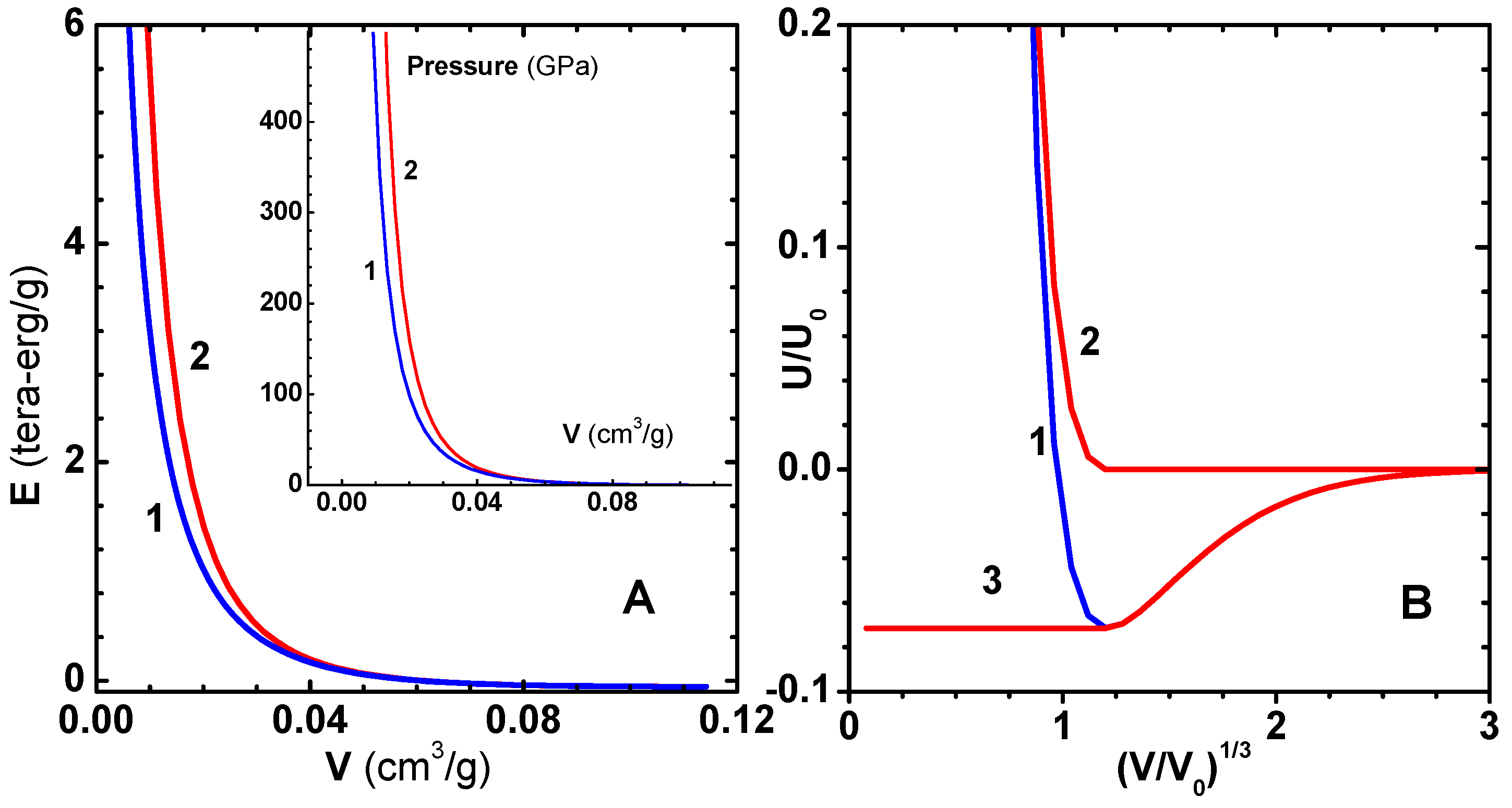
Here, B i n t ( V ) is a suitable interpolating function. Note that, by definition, E c o l d ( V ) is continuous at V m . Now, the parameters b k ( k = 1 , 3 ) in B i n t ( V ) are chosen such that P c o l d ( V ) and its first two derivatives are also continuous at V m [12]. This procedure gives a smooth transition from the four-parameter model to the QSM. Plots of energy versus V for Cu using the two models are shown in Figure 1A with the choice V m = V c 0 / 1.4 = 0.07998 cm 3 /g.
As an application of the zero-temperature energy E c o l d ( x ) , we use the lattice inversion method [21] and obtain an effective inter-particle potential between Cu atoms in the solid. We may imagine that the lattice is formed by assembling shells successively around a central atom. Then, the zero-temperature energy E c o l d ( x ) per atom, where x = ( V / V c 0 ) 1 / 3 is the scaled nearest-neighbor distance, can be readily written as a lattice sum involving the inter-particle potential U ( x ) . The inversion method provides a similar formula [22] for U ( x ) in terms of E c o l d ( x ) . For an FCC lattice, the direct formula for E c o l d ( x ) and the inverse formula for potential U ( x ) are given by
E c o l d ( x ) = 1 2 n = 1 N s r n U ( b n x ) , U ( x ) = 2 n = 1 N s w n E c o l d ( b n x ) .
Here, n is the shell index, r n is the number of atoms in the shell, b n is the normalized radius of the shell, and w n is the weight factor for the shell. This is a truncated formula, and the total number ( N s ) of shells considered should be sufficiently large for convergence. The total potential (curve-1) and its repulsive (curve-2) and attractive (curve-3) components, as per the Weeks–Chandler–Andersen prescription [23], are shown in Figure 1B. For the sake of completeness, we have listed the constants r n , b n and w n ( 1 n N s ) for FCC lattice in Table 1. The factors 1 / 2 and 2 in Equation (7) arise because U ( x ) is the energy for two atoms; while E c o l d ( x ) is the energy per atom.

4. Ionic Thermal Component

The treatment of the ionic contribution to the EOS is best described by considering the compressed region and the expanded volume regions separately. In the former, we start with the low-temperature solid phase and go over to the melted fluid phase on increasing temperature. However, in the latter region, the material is always in the fluid phase, which also encompasses what is called the warm dense matter region. We consider different models for describing the EOS in these regions.

4.1. Compressed Region—Johnson’s Model

The model for ionic thermal energy should describe the low-temperature properties of solids, fluid phase for temperatures above melting, and ideal gas behavior at higher temperatures. Thus, for a specified volume, the constant-volume molar specific heat of ions—denoted by C V i —must vary from the low temperature T 3 law to 3 R above Debye’s temperature and finally to 3 R / 2 . This feature is essential since shock compression of materials produce high temperatures and the solid melts and becomes a fluid after shock traversal. The mean field model used by Wang does not possess this crucial feature [24]. The parameters in the model used by Kormer et al. [25] need adjustments for every material.
So, we propose to use Johnson’s ionic model [26] in the compressed region. In addition to the general constraints on C V i mentioned above, the model adds an extra contribution (3RT/Tm), linearly varying with T in the interval T m to 1.2 T m to account for the heat of fusion. This corresponds to an increment of 0.6 R in entropy, which has been determined from studies of several materials. Furthermore, the typical decrease of C V i from its value 3 R at T m to 9 R / 4 at 5 T m —and thereafter a linear variation in ln ( T ) to the ideal gas value 3 R / 2 —are built in to the model. Specific internal energy and pressure within the model (version-I) are thus given by [26]:
E t i ( V , T ) = E D + N k B T ( E 0 + ϵ ψ ) .
P t i ( V , T ) = Γ i V E D + 1 V ( 2 Γ i 2 / 3 ) N k B T ( E 0 + ϵ ψ ) , E D ( V , T ) = N k B T [ 9 8 θ D T + 9 ( T θ D ) 3 0 θ D / T z 3 e z 1 d z ] .
Here, E D is Debye’s specific internal energy, T M ( V ) is melting temperature, θ D ( V ) is Debye’s temperature, k B is Boltzmann’s constant, N is number of atoms per gram, and ψ = T / T M is scaled temperature. Further, Γ i (V) is Grüneisen parameter for ions, to be defined below. The energy parameters E 0 and ϵ ψ are fitted functions of ψ in order to account for the constraints on C V i mentioned above, and are given by
E 0 = 3 2 + 3 2 a 4 ( ψ 3 / 2 ψ 2 / 2 ) + a 2 ( a 3 y + ψ 1 y ) ( ψ y ( a 3 + ψ 1 y ) 2 ) , 1 ψ < , ϵ ψ = 3 2 ( ψ 1 / ψ ) , 1 ψ 1.2 , ϵ ψ = 0.66 / ψ , 1.2 ψ < .
Thus, Johnson starts with Debye’s model in the region T T m . The contribution to specific internal energy due to heat of fusion is given by ϵ ψ ; and E 0 describes the variation of C V i after melting. Note that E 0 varies from zero at T m to 3 / 2 in the high temperature limit. An equally important feature is that the factor ( 2 Γ i 2 / 3 ) facilitates correct approach of the effective Γ i to its ideal gas limit (2/3). The constants a 2 , a 3 , a 4 , which take care of the constraints, are given by
a 1 = 5.7 i n i ln [ ( A i / A ¯ ) 3 / 2 / n i ] , a 3 = 200 , y = ( 201 [ 1600 a 1 2 + 2398 ( 4 a 1 + 5 ) ] 1 / 2 40 ( 5 197 a 1 ) ) / [ 3980 ( 4 a 1 + 5 ) ] , a 2 = 3 2 ( 1 + a 3 ) 3 / [ a 3 ( 1 y ) ( a 3 y + 2 y ) ] , a 4 = 8 5 ( a 1 + a 2 / ( 1 + a 3 ) ) ,
where, n i , A i , and A ¯ denote the number fraction, mass number, and its average, respectively. The summation in a 1 , which contributes only for mixtures, accounts for ideal entropy mixing. Thus, the model is applicable to the case of compounds as well.
In a more elaborate method (version-II), region 1 ψ < is divided into three segments, viz., 1 ψ 5 , 5 ψ ζ , and ζ ψ < . In the first region, C V i varies linearly in T; while in the the second, the variation is linear in ln ( T ) . The value of ζ is determined so that entropy approaches ideal gas limit. Heat of fusion is added, as in the first version. Finally, specific energy and pressure are expressed as
E t i ( V , T ) = E D + N k B T ( E ψ + ϵ ψ ) ,
P t i ( V , T ) = Γ i V E D + 1 V ( 2 Γ i 2 / 3 ) N k B T ( E ψ + ϵ ψ ) ,
where ϵ ψ is the same as that given in Equation (11), while E ψ is given by
E ψ = 3 / 16 3 ψ / 32 3 / ( 32 ψ ) , 1 ψ 5 , E ψ = ( 3 / 4 ) + b ln ( ψ / 5 ) b + 5 ( b + 9 / 20 ) / ψ , 5 ψ ζ , E ψ = ( 3 / 2 ) + 5 ( b + 9 / 20 ) / ψ ζ b / ψ , ζ ψ < .
The new constants b and ζ are given by
b = 9 / ( 32 ( a 1 + 3 / 4 + 27 ln ( 5 ) / 16 ) ) , ζ = 5 exp [ 3 / ( 4 b ) ] .
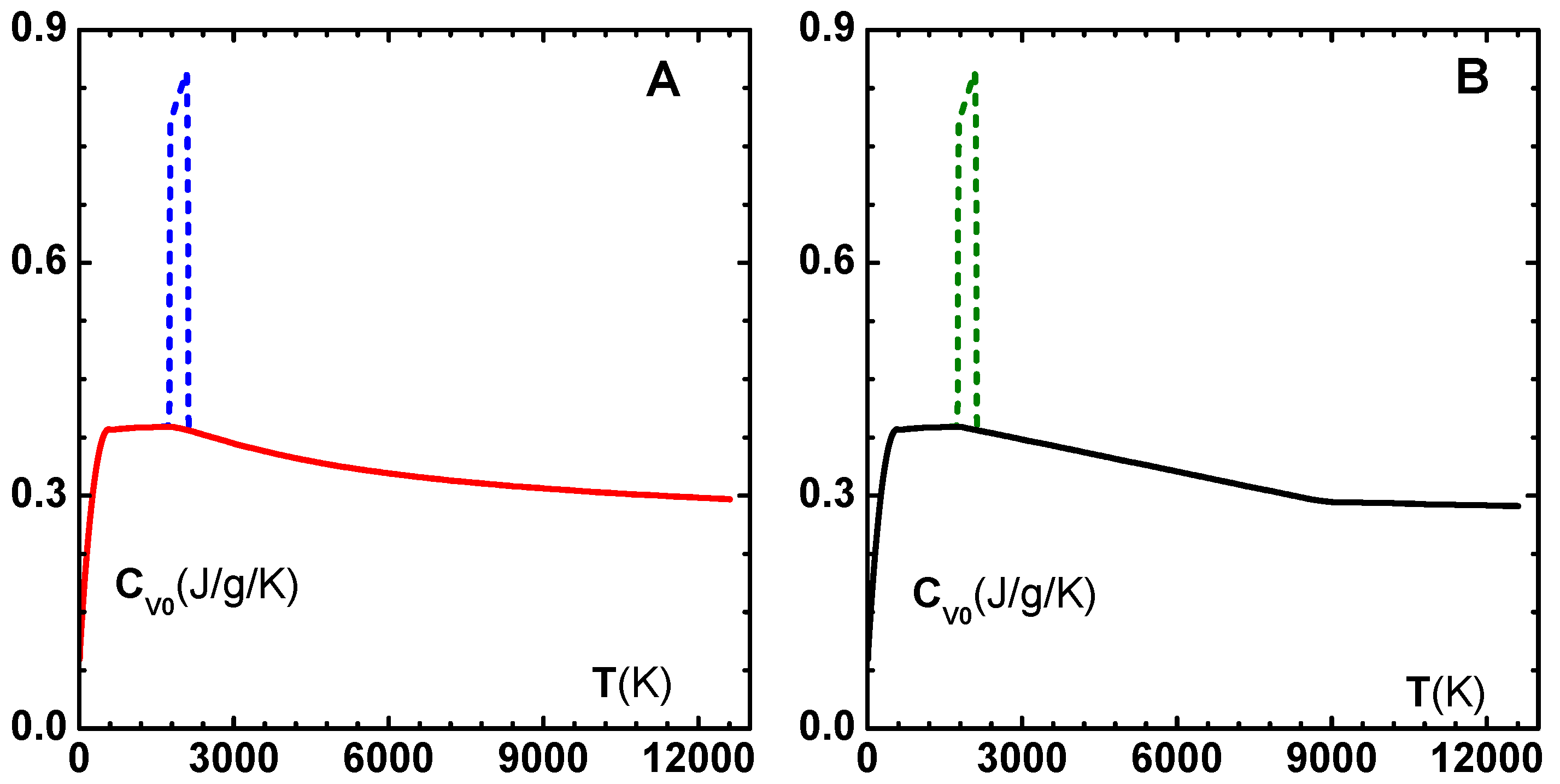
For illustration, we show in Figure 2 the variation of specific heat of Cu with temperature at normal volume V 0 , using first version in graph-A and second version in graph-B. Both versions, thus, produce almost identical results. From the discussion summarized above, it is clear that Johnson’s model is to be used in the compressed volume region. So, we next discuss a suitable model in the expanded volume region.

4.2. Expanded Region—Modified Soft-Sphere

The expanded volume region of the material, which covers the warm dense region and liquid–vapor transition, is important in several hydrodynamic applications. For instance, the material undergoing expansion induced via rarefaction wave is in this region. Similarly, highly porous materials (e.g., copper with porosity more than fifty percent) reach this state after shock-compression. It is necessary to have a separate model for this region as the physics here is mainly determined with excluded volume effect and a weak van der Waals type attractive interaction [27]. Young developed a soft-sphere model for liquid metals [28] using Monte Carlo simulations data for the thermal properties of particles interacting via soft-sphere potential, ϵ ( σ / r ) n . Here, ϵ , σ , and n define the parameters of the inverse power law potential. Together with the van der Waals attractive interaction, five parameters in the model were fitted to liquid–vapor co-existence data. This procedure is an extension of van der Waals theory of fluids, which treats attractive part as a zero temperature component of the EOS. We developed a modified soft-sphere model [29], wherein the use of simulation data was retained, however a generalized Lennard–Jones model was used as the attractive component. Instead of numerical fitting, all the parameters of the modified model were determined in terms of V c 0 , E c o h , B 0 , and B 0 at normal conditions.
To discuss the formulation briefly, we start with a generalized Lennard–Jones pair potential between the atoms:
U L J ( R ) = ϵ r e p ( σ R ) n ϵ a t t ( σ R ) m .
Here, respectively, ϵ r e p and ϵ a t t denote repulsive and attractive energy parameters, and σ is a spatial scale factor. This particular form is chosen because, as already mentioned above, extensive simulation data is available [27] for the repulsive component in Equation (15). Further, a proper choice of the exponent m will lead to an attractive part similar to that in van der Waals theory. The zero-temperature ionic energy per gram, E L J = N E L J , where E L J is the energy per atom, can be expressed as
E L J ( V ) = N ϵ r e p 2 C n ( V c 0 V ) n / 3 N ϵ a t t 2 C m ( V c 0 V ) m / 3 ,
where V c 0 = N σ 3 / 2 is the specific volume at zero-temperature, and C n and C m are lattice sums [30]. Now, on imposing the conditions that the zero-temperature pressure P L J = d E L J / d V vanishes at V c 0 and the corresponding energy E L J ( V c 0 ) = E c o h , we readily find that
ϵ r e p = E c o h N 2 C n m n m , ϵ a t t = E c o h N 2 C m n n m .
The expressions for E L J and P L J can be re-written as
E L J ( V ) = E c o h n m [ m ( V c 0 V ) n / 3 n ( V c 0 V ) m / 3 ] ,
P L J ( V ) = E c o h n m n m 3 V c 0 [ ( V c 0 V ) 1 + n / 3 ( V c 0 V ) 1 + m / 3 ] .
The exponents n and m are yet to be determined, however, bulk modulus B 0 and its pressure derivative B 0 can be computed from Equation (19) as
B 0 = E c o h n m 9 V c 0 , B 0 = 2 + n 3 + m 3 .
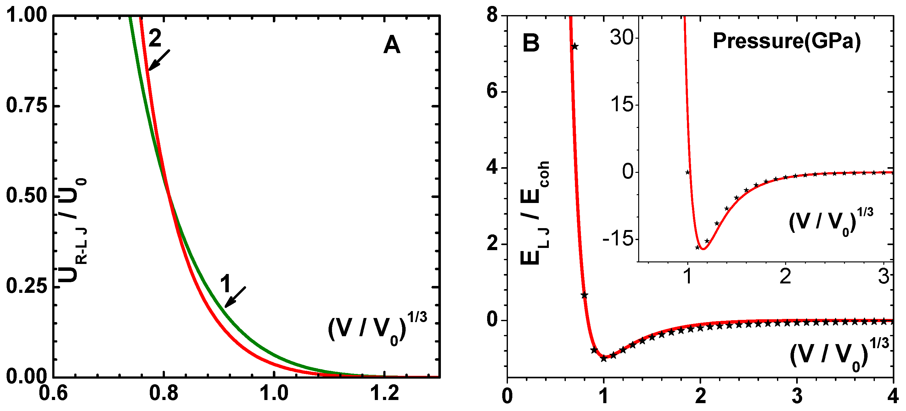
Even though these relations imply that n and m are the roots of the quadratic equation x 2 3 ( B 0 2 ) x + 9 B 0 V c 0 / E c o h = 0 , experimental parameters generally lead to complex roots [31]. Therefore, in such situations, we can use only three parameters. Jiuxun has shown [32] that the spinodal condition | B | ( P P * ) , where P * is the pressure corresponding to B ( P * ) = 0 , follows if we use the relation m = ( n 3 ) / 2 . Then, the first relation in Equation (20) shows that n is determined from the quadratic equation n 2 3 n 18 B 0 V c 0 / E c o h = 0 . The positive root gives n = 8.803 and m = 2.901 for Cu. The accuracy of the generalized Lennard–Jones model can be assessed by comparing it with the four-parameter model [16] discussed earlier. In Figure 3A, we compare the repulsive component of the interparticle potential for Cu. The energy parameter ϵ r e p and the exponent n in the repulsive component are to be used in the model for ionic thermal energy. Figure 3B shows the generalized Lennard–Jones energy and pressure, which compare quite well.
As explained in the beginning of this section, the ionic thermal energy of the modified soft-sphere model is precisely contributed by the repulsive part of the inter-particle potential. Monte Carlo simulation data of thermal pressure of soft particles, interacting via the potential ϵ r e p ( σ / r ) n , are accurately expressed in the parametric form [27]:
P = N k B T V [ 1 + n 3 C n 2 ( ρ s c 2 ) n / 3 + 1 18 n ( n + 4 ) ( ρ s c 2 ) n / 9 ] , ρ s c = N V σ 3 [ ϵ r e p k B T ] 3 / n .
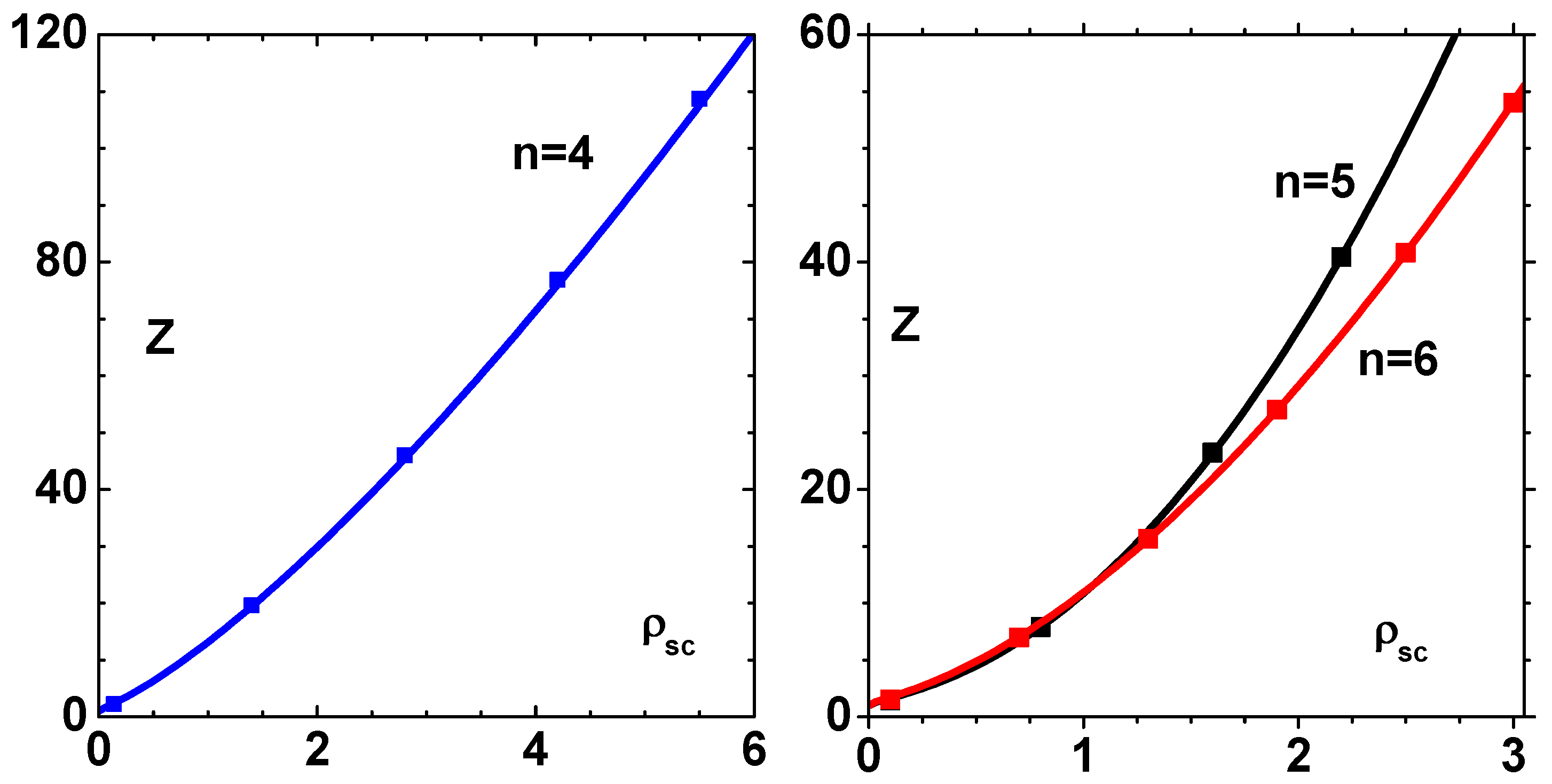
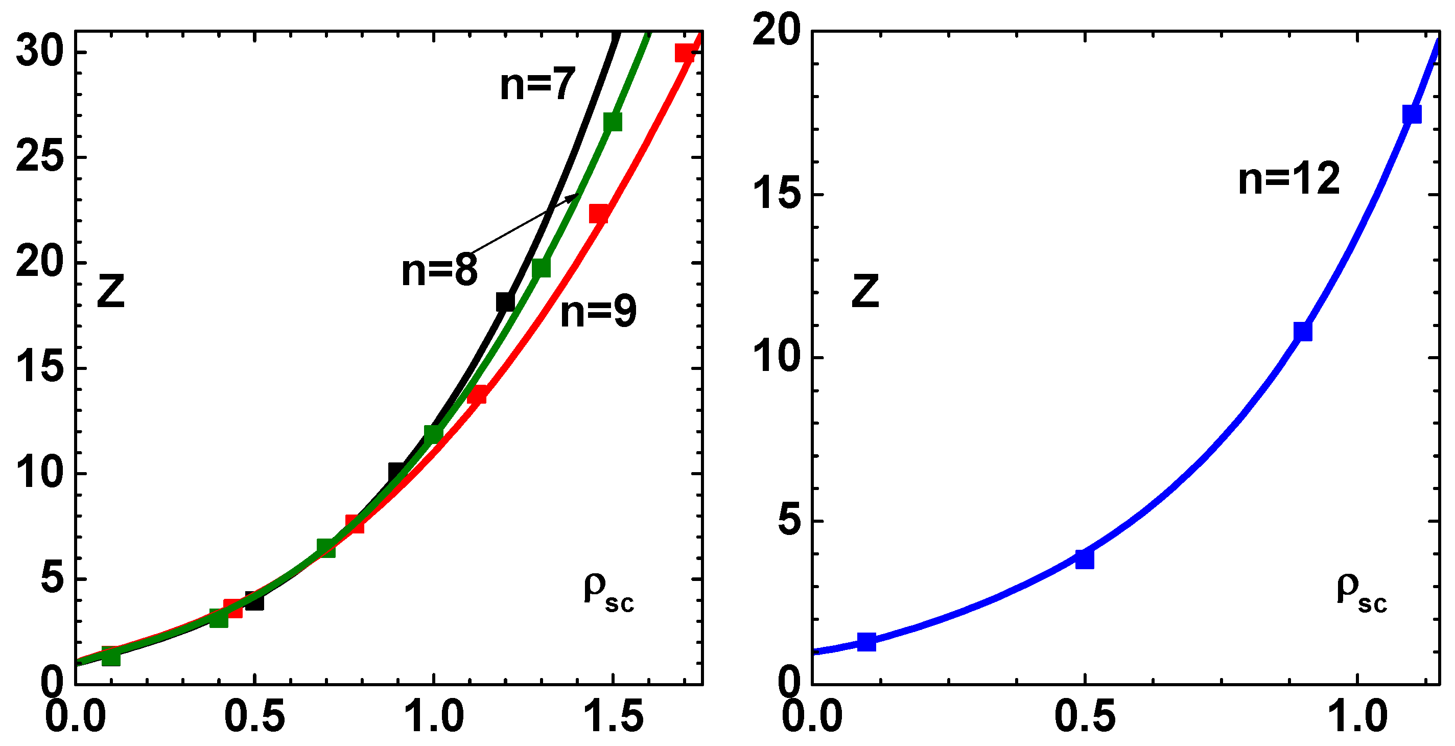
We show the accuracy of this fit in Figure 4, where the scaled pressure Z = P V / ( N k B T ) is plotted versus the scaled density, denoted as ρ s c , for values of exponent n = 4 , 5 , 6 . Similar results for the exponent n = 7 , 8 , 9 , 12 are shown in Figure 5. Impressive agreement between the data and the parametric fit is evident in these figures. On adding this contribution to E L J and P L J , the ionic energy and pressure within the modified soft-sphere model are given by
E s o f t ( V , T ) = N k B T [ 3 2 + 1 6 ( n + 4 ) ( V c 0 V ) n / 9 ( ϵ r e p N k B T ) 1 / 3 ] + E L J ( V ) ,
P s o f t ( V , T ) = N k B T V [ 1 + 1 18 n ( n + 4 ) ( V c 0 V ) n / 9 ( ϵ r e p N k B T ) 1 / 3 ] + P L J ( V ) ,
where we have used the expression for zero-temperature reference volume, V c 0 = N σ 3 / 2 , and the subscript s o f t to denote the term ‘soft-sphere’.
As mentioned earlier, the zero-temperature isotherms of the solid and the correction to ideal gas thermal energy (second term in brackets), determined from Monte Carlo simulation data, define the modified soft-sphere model. All the parameters in this model are determineda priori, so there is no need to fit its parameters.

4.3. Grüneisen Parameter

Ionic Grüneisen parameter Γ i ( V ) , Debye temperature θ D ( V ) , and melting temperature T M ( V ) are needed in modeling ionic energy and pressure in the compressed volume region. While there are several empirical fits [13] for Γ i ( V ) , the one due to Preston et al. [33], which has the correct asymptotic behavior for strong compression, is expressed as
Γ i ( V ) = 1 2 + c 1 V 1 / 3 + c 2 V q .
The parameters c 1 , c 2 , and q are determined using experimental data on Γ i at T = 300 K, at zero-pressure melting point and asymptotic ( V 0 ) approximation for free electron states. These constraints define three nonlinear equations to determine the parameters. Expressions for θ D ( V ) and T M ( V ) , which follow from Debye–Grüneisen law and Lindemann’s law, respectively, are given by
θ D ( V ) = θ 0 ( V 0 V ) 1 / 2 exp [ 3 c 1 ( V 0 1 / 3 V 1 / 3 ) + c 2 q ( V 0 q V q ) ] .
T M ( V ) = T M 0 ( V r V ) 1 / 3 exp [ 6 c 1 ( V r 1 / 3 V 1 / 3 ) + 2 c 2 q ( V r q V q ) ] .
Values of θ 0 , T M 0 , and V r , which reference Debye temperature, melting temperature, and melting volume at P = 0 , respectively, are tabulated for a variety of materials [33]. Further, the expression for T M ( V ) is found to compare well with experimental data, as shown below.
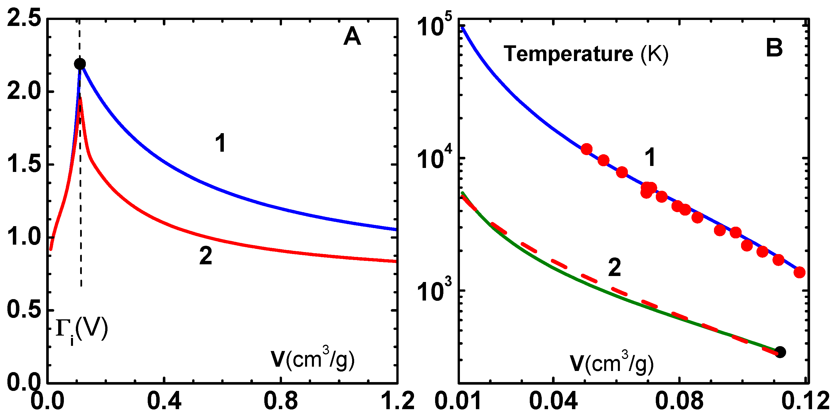
As an application of the models discussed in this section, we show the Grüneisen parameter for Cu in the compressed ( V V 0 ) as well as the expanded ( V V 0 ) volume regions for 300 K (curve-1) and 5000 K (curve-2) in Figure 6A. The region to the left of the (vertical) dashed line in the figure is the compressed phase while the expanded region is on its right side. The thermodynamic definition for ionic Grüneisen parameter, Γ i = ( 1 / V ) ( P / E ) V = ( 1 / V ) ( P / T ) V ( 1 / C V i ) , can be readily used with analytical expressions for P and E, which are described in both volume regions (Johnson’s model for V V 0 ; and the modified soft-sphere model for V V 0 ). Experimental value 2.19 at 300 K is also shown (filled circle) in the figure. For a specified temperature, say 5000 K, the material goes over to the melted fluid region as volume is increased, and hence Γ i ( V 0 ) is reduced to 1.96 from its value at 300 K. For the expanded volume region, the modified soft-sphere model shows explicit temperature dependent of Γ i ( V ) .
In Figure 6B, we have also sketched θ D ( V ) and T M ( V ) , given in Equations (25) and (26). Experimental data on T M taken from Preston et al. [33], and the value of θ D ( V 0 ) are also shown. Good comparison of T M data, which are not used in fixing the parameters in Γ i ( c 1 , c 2 , and q in Equation (24)), shows the internal consistency of the procedure. In addition, we have shown θ D (dashed line) derived from Slater’s formula, Γ i = ( 1 / 6 ) ( 1 / 2 ) ( d B S / d P ) [11], where B S is the zero-temperature bulk modulus obtained from Equation (4). Again, the agreement between θ D obtained from two totally independent sources (Preston’s and Slater’s Γ i ) demonstrates its accuracy.

5. Electronic Thermal Component

Electronic thermal component of energy and pressure is significant at temperatures reached in shock compression of porous materials. The EOS codes mentioned earlier uses the well-known Thomas–Fermi (TF) model [14] to describe electronic properties. However, the pressure and energy resulting from the approximations involved in this model need to be corrected in the low-temperature range. For example, the low-temperature specific heat constant predicted by the model differs from experimental values. Further, it is necessary to employ pressure and energy tables since in-line solutions of the TF equation are time consuming. Therefore, analytical fits [34] to results of Latter’s calculations are sometimes employed [25] in high-pressure studies. However, it is important to note that this fit is valid in the compressed volume region, even though TF model as such may be applied even to an isolated atom.
So, we propose a somewhat different approach. First of all, following Atzeni et al [35], we assume that the Fermi gas model can be used to compute the thermal energy and pressure of electrons with a suitable average ionization degree Z * of atoms, which depends on density and temperature. We use an excellent analytical fit for Z * given by More [36] using results of Thomas–Fermi model:
R 5 = ρ ( g / c m 3 ) / ( Z n A ) , t c = T ( e v ) / A 4 / 3 , t = t c / ( 1 + t c ) , a 5 = 3.323 × 10 3 × t c 0.971832 + 9.26148 × 10 5 × t c 3.10165 , b 5 = exp [ 1.763 + 1.43175 × t + 0.315463 × t 2 ] , c 5 = 0.36667 × t + 0.98333 , q 6 = a 5 × R 5 b 5 , q 5 = ( factor × R 5 c 5 + q 6 c 5 ) 1 / c 5 , x 5 = 14.3139 × q 5 0.6624 , Z * = Z n × x 5 / ( 1 + x 5 + [ 1 + 2 x 5 ] 1 / 2 ) ,
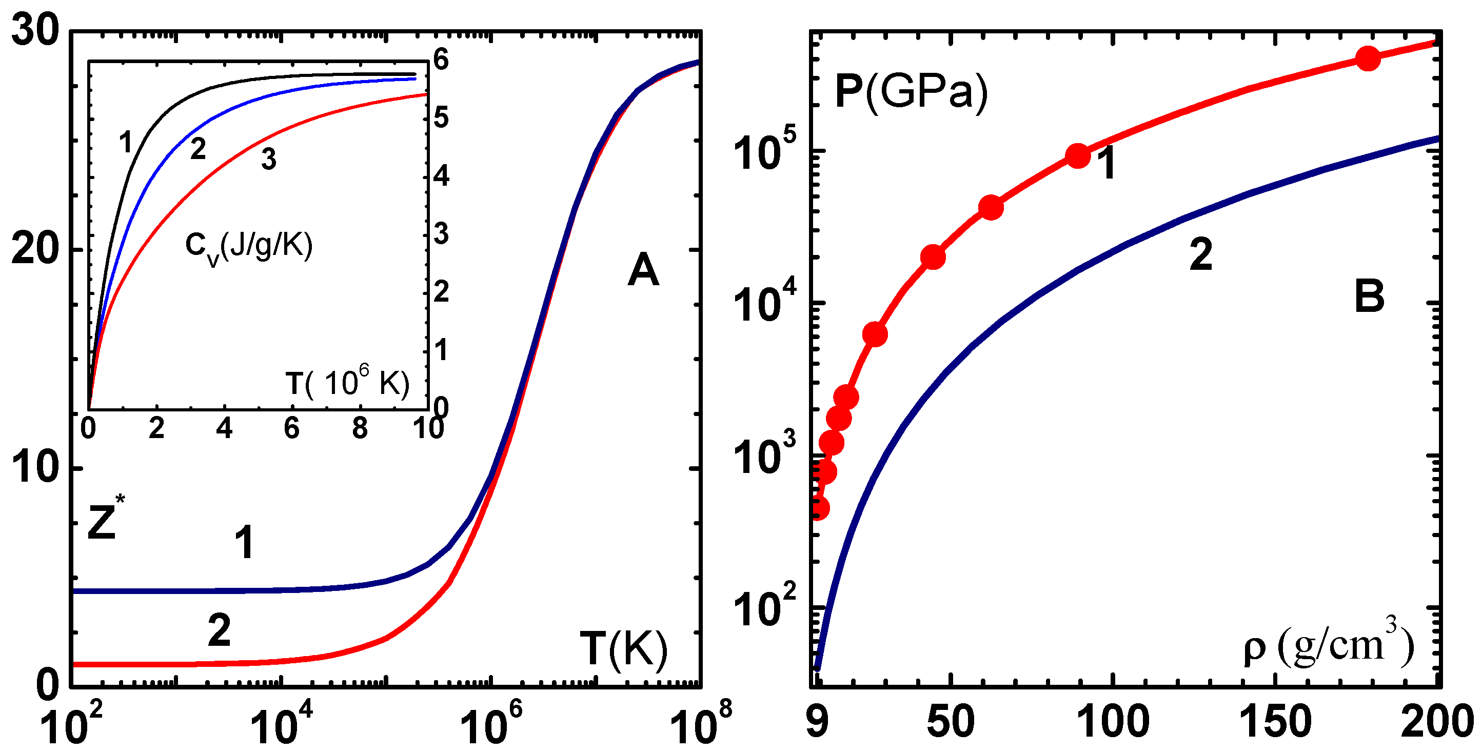
where Z n and A are atomic number and mass number, respectively. We have introduced a multiplicative correction term, termed ‘factor’ in the equation above, which needs to be adjusted so that Z * agrees with the experimental value of average ionization degree at ρ 0 and T 0 . It takes value 0.079 for Cu, and the corrected and uncorrected variation of Z * with temperature is shown in Figure 7A. Note that Z * is corrected only in the lower ranges of temperature, and it correctly saturates to Z n at high temperature. The insert in this figure shows specific heat variation for three densities: (1) ρ 0 / 10 , (2) ρ 0 , and (3) 10 ρ 0 . Similar correction factors for some other metals are given in Table 2.
To test this approach, we have plotted in Figure 7B the zero-temperature electron pressure P = C p ( N Z * / V ) 5 / 3 ) , where C p = ( 3 / π ) 2 / 3 ( h 2 / 20 m e ) versus density ( ρ ) using the uncorrected (curve-1) and corrected (curve-2) formula for Z * . Numerical results [37] employing TF theory (filled circles) are also shown. It is interesting to note the TF results are accurately reproduced with the uncorrected Z * , while the correction gives lower pressures. Finally, the thermal component of electron energy and pressure, within the free electron gas model, are given by
N V Z * = C 0 ( k B T ) 3 / 2 I 1 / 2 [ E F / k B T ) ] .
E e [ V , T ] = C 0 ( k B T ) 5 / 2 V I 3 / 2 [ E F / k B T ) ] 3 5 ( N Z * ) E F ( V , 0 ) .
P e [ V , T ] = 2 3 1 V E e [ V , T ] , C 0 = 4 π h 3 ( 2 m e ) 3 / 2 .
Here, E F ( V , T ) is the Fermi energy, which is implicitly defined via Equation (28); and I n are Fermi–Dirac integrals. Very accurate rational approximations for these integrals are now available [38]. The next level of improvement to the electron EOS is to add Coulomb interaction, exchange, and correlation energies, thereby accounting for all the terms in the uniform electron gas model [39].

6. Applications

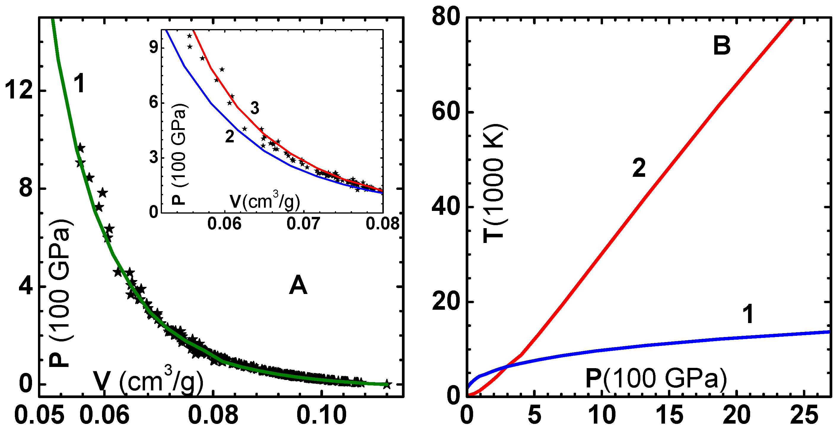
In this section, we discuss three more applications of the EOS model. The first is its application to the calculation of the shock Hugoniot. Extensive data available in the shock wave database [40] is compared in Figure 8A with predictions of the model (curve-1). We find excellent agreement throughout the range of pressures obtained in the experiments. In the insert figure, we have shown the results without correcting the zero-temperature isotherm (curve-2), and without adding electronic terms (curve-3). Correction to the zero-temperature isotherm is found to be quite important as the four-parameter isotherm is valid up to 100–150 GPa. Addition of the electron component is found to improve the prediction even for pressures in the range of 200 GPa. Contrary to the common feeling, pressure on the Hugoniot is decreased when electron contribution is added. This is because the electron degrees of freedom reduces temperature, and consequently the pressure, for a specified volume on the Hugoniot. Temperature along the Hugoniot (curve-1) and the melting temperature (curve-2) displayed in Figure 8B show that melting occurs around 300 GPa pressure. Therefore, proper accounting of the melting transition is important even though the transition is not evident in the pressure–volume Hugoniot.
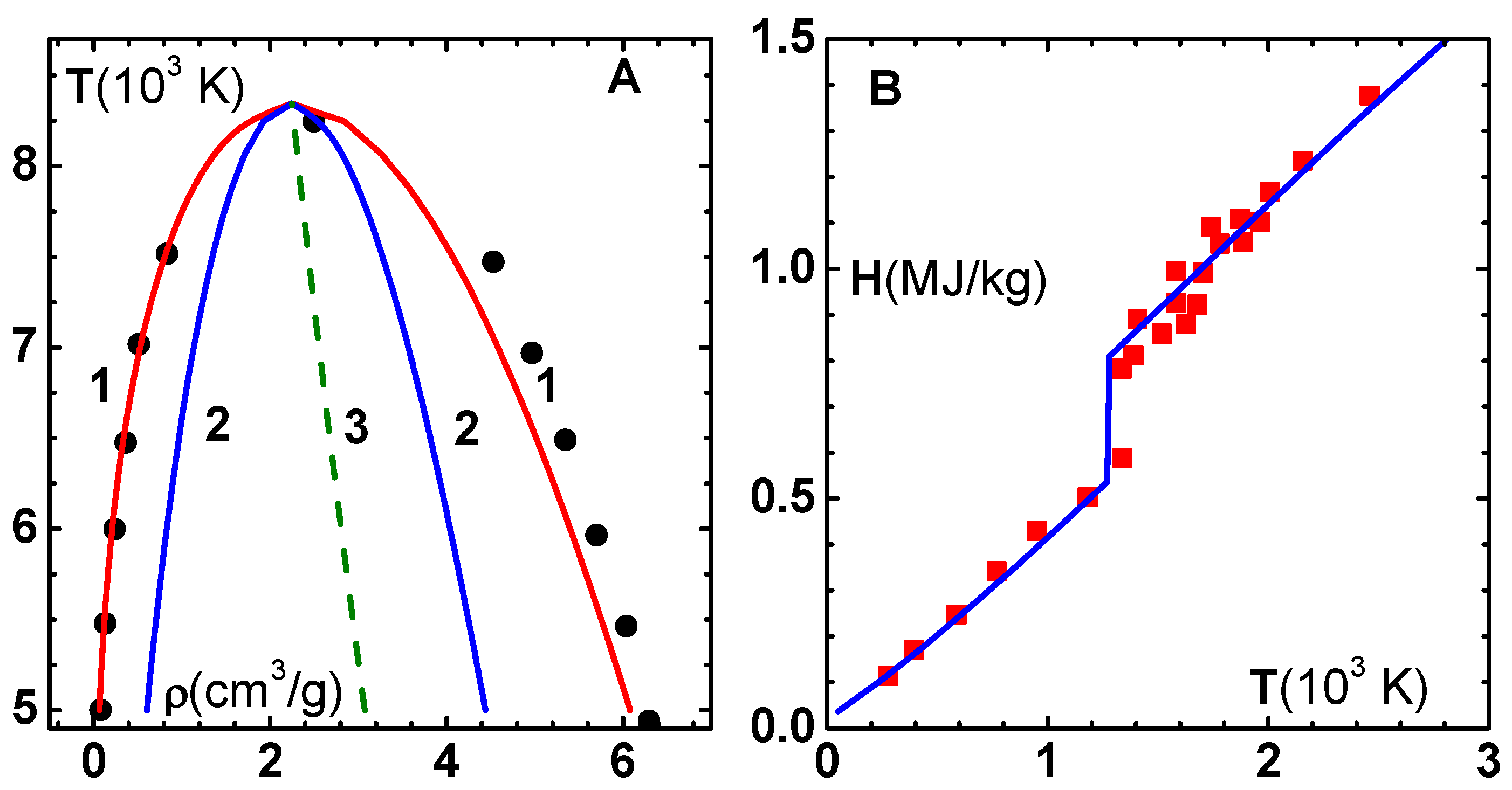
Next, we compare the liquid–vapor phase diagram of Cu employing the modified soft-sphere model, which was briefly considered in our earlier work [29]. It is well known that the attractive and thermal components of energy finely balance to produce the van der Waals loops in the isotherms in the vapor–liquid co-existence region. The critical point parameters we have obtained, via Maxwell’s construction, ( ρ c = 2.246 g/cm 3 , T c = 8345 K, and P c = 0.8935 GPa) are very well within the range quoted in the literature [41]. The phase diagram (curve-1) is shown in Figure 9A, and compared with simulation data (filled circles) [42]. These data were obtained via molecular dynamics simulations using an effective pair potential deduced from DFT calculations of energy–volume curve in the compressed and expanded volume regions. We find good comparison except in the liquid region of the phase diagram. The spinodal curve (curve-2), which is the locus of points where isothermal compressibility diverges; and the diameter (curve-3), which is the average of liquid and vapor phase densities on the phase diagram, are also shown in the figure.
In Figure 9B, we have compared results of the EOS model for the enthalpy (H) of Cu versus temperature, along the 1-bar isobar, with experimental data taken from Trainor et al. [43]. Starting from 50 K, the material expands from 0.1105 to 0.1268 (cm 3 /g), where it crosses the melting line around 1310 K. This results in a jump in enthalpy, and thereafter a smooth increase, as seen from the figure. The model for Γ i employed in Johnson’s model is inappropriate in this volume region. Therefore, we have taken a constant value Γ i = 2.19 , which is the experimental value at normal conditions, and corresponding expressions for θ D ( V ) and T M ( V ) in lieu of Equations (25) and (26). Furthermore, we find that the heat of fusion to be added at the melting point is about 225 kJ/kg, in good agreement with the experimental value of 205 kJ/kg.
Finally, we mention that the EOS model described above (except the correction term for the zero-temperature isotherm and the free electron gas model) has been applied very successfully for the development and application of enthalpy-based approach to describe shock wave propagation in porous materials. There, we started with the computation of enthalpy-parameter, defined as χ = P ( V / H ) P , and developed the method treating P as independent variable. First, we showed [5] (using analytical fits [34] to results of TF theory) the correct approach to incorporate electronic effects explicitly. Then, we developed the modified soft-sphere model to properly evaluate the Hugoniot of highly porous materials, as their final shocked states are in the fluid region [29]. In another development, we used the EOS to show that the enthalpy-based approach can be implemented [44] in hydrodynamic simulations to describe shock wave propagation in solid as well as porous materials.
Applications of the EOS model to other materials can be easily carried out using the experimental/theoretical values of the parameters [16,33] employed in the different components of the model. A list of these parameters for Cu, Al, Fe, and W is given in our earlier publication [44].

7. Summary

The main aim of this paper is to discuss the basic components of an EOS model for metals for high-pressure physics applications. Thus, we started with the division of the EOS in to three parts: Zero-temperature isotherm, thermal ionic component, and thermal electronic component. This division is convenient as there are theories of different levels of sophistication dealing with them. We mentioned that results of DFT-based electronic structure calculations can be suitably fitted into a functional form, as is done in the case of the four-parameter model. A method to correct this model—which is only valid in the lower pressure range, so as to approach the results of the quantum statistical model—was discussed. Similarly, in lieu of detailed lattice dynamic calculations for density of states of lattice vibration modes, we have used the simple Debye model with a suitable form for volume dependence of Debye temperature. However, we have stressed the need for incorporating the energy of fusion due to melting in the thermal ionic component. A model for this component, which incorporates continuous temperature dependence of constant volume-specific heat, was discussed. It is the valence electrons in the metal which contribute to the thermal electronic component, which we modeled using the results of the Fermi gas model. However, we have shown that the degree of ionization, and hence the free electron density, can be determined from the Thomas–Fermi model. A simple correction to get the experimental electron density at normal conditions was also discussed. Finally, for the purpose of demonstration, the model was applied to calculate the shock-Hugoniot, liquid-vapor phase diagram, and isobaric expansion of Cu. We hope that the model described here can be used to generate tables for hydrodynamic applications of impact experiments, shock wave studies, and above all, design and analysis of high-energy-density systems.
Author Contributions

S.V.G.M.—conceptualization, methodology, formal analysis, investigation, software, validation, writing-review and editing; B.N.—investigation, validation and editing.

Funding

This research received no external funding.

Acknowledgments

The authors would like to thank the reviewers of Condensed Matter Journal for critical reviews and suggestions to improve the presentation of the paper.

Conflicts of Interest

The authors declare no conflict of interest.

References

  1. Zeldovich, Y.B.; Raizer, Y.P. Physics of Shock Waves and High-Temperature Hydrodynamic Phenomena; Academic: New York, NY, USA, 1967. [Google Scholar]
  2. Tillotson, J.H. Metallic Equations of State for Hypervelocity Impact; Report GA-3216; General Atomic Division of General Dynamics: San Diego, CA, USA, 1962; Unpublished. [Google Scholar]
  3. Rice, M.H.; Walsh, J.M. Equation of State of Water to 250 Kilobars. J. Chem. Phys. 1957, 26, 824. [Google Scholar] [CrossRef]
  4. Wu, Q.; Jing, F. Thermodynamic equation of state and application to Hugoniot predictions for porous materials. J. Appl. Phys. 1996, 80, 4343. [Google Scholar] [CrossRef]
  5. Nayak, B.; Menon, S.V.G. Explicit accounting of electronic effects on the Hugoniot of porous materials. J. Appl. Phys. 2016, 119, 125901. [Google Scholar] [CrossRef]
  6. More, R.M.; Warren, K.H.; Young, D.A.; Zimmerman, G.B. A new quotidian equation of state (QEOS) for hot dense matter. Phys. Fluid 1988, 31, 3059. [Google Scholar] [CrossRef]
  7. Young, D.A.; Corey, E.M. A new global equation of state model for hot, dense matter. J. Appl. Phys. 1995, 78, 3748. [Google Scholar] [CrossRef]
  8. Baroni, S.; Giannozzi, P.; Isaev, E. Thermal properties of materials from ab-initio quasi-harmonic phonons. arXiv 2011, arXiv:1112.4977. [Google Scholar]
  9. Belmonte, D. First Principles Thermodynamics of Minerals at HP–HT Conditions: MgO as a Prototypical Material. Minerals 2017, 7, 183. [Google Scholar] [CrossRef]
  10. Chisolm, E.D.; Crockett, S.D.; Wallace, D.C. Test of a theoretical equation of state for elemental solids and liquids. Phys. Rev. B 2003, 68, 104103. [Google Scholar] [CrossRef] [Green Version]
  11. Otero-de-la-Roza, A.; Abbasi-Pérez, D.; Luaña, V. Gibbs2: A new version of the quasiharmonic model code. II. Models for solid-state thermodynamics, features and implementation. Comp. Phys. Commun. 2011, 182, 2232. [Google Scholar] [CrossRef]
  12. Kerley, G.I. User’s Manual for PANDA II- A Computer Code for Calculating Equation of State; Sandia Report, SAND88-229.UC-405; Sandia National Labs.: Albuquerque, NM, USA, 1991.
  13. Godwal, B.K.; Sikka, S.K.; Chidambaram, R. Equation of state theories of condensed matter up to about 10 TPa. Phys. Rep. 1983, 102, 121. [Google Scholar] [CrossRef]
  14. Latter, R. Thermal behavior of Thomas-Fermi statistical model of atoms. Phys. Rev. 1955, 99, 1854. [Google Scholar] [CrossRef]
  15. Holzapfel, W.B. Physics of solids under strong compression. Rep. Prog. Phys. 1996, 59, 29. [Google Scholar] [CrossRef]
  16. Li, J.H.; Liang, S.H.; Guo, H.B.; Liu, B.X. Four-parameter equation of state and determination of the thermal and mechanical properties of metals. J. Alloys Comp. 2007, 431, 23. [Google Scholar] [CrossRef]
  17. Rose, J.H.; Smith, J.R.; Guinea, F.; Ferrante, F. Universal features of the equation of state of metals. Phys. Rev. B 1984, 29, 2963. [Google Scholar] [CrossRef]
  18. Vinet, P.; Ferrante, F.; Smith, J.R.; Rose, J.H. Universal equation of state for solids. J. Phys. Condens. Matter 1989, 1, 1941. [Google Scholar] [CrossRef]
  19. Kalitkin, N.N.; Kuz’mina, L.V. Curves of cold compression at high pressures. Sov. Phys. Solid State 1972, 13, 1938. [Google Scholar]
  20. More, R.M. Quantum-statistical model for high-density matter. Phys. Rev. A 1979, 19, 1234. [Google Scholar] [CrossRef]
  21. Chen, N.X.; Chen, Z.D.; Shen, Y.N.; Liu, S.J.; Li, M. 3D inverse lattice problems and Mobius inverssion. Phys. Lett. A 1994, 184, 347. [Google Scholar] [CrossRef]
  22. Mookerjee, A.; Chen, N.X.; Kumar, V.; Satter, M.A. Ab initio pair potentials for FCC metals: an application of the method of Mobius transformation. J. Phys. Condens. Matter 1992, 4, 2439. [Google Scholar] [CrossRef]
  23. Weeks, J.D.; Chandler, D.; Andersen, H.C. Role of Repulsive Forces in Determining the Equilibrium Structure of Simple Liquids. J. Chem. Phys. 1971, 54, 5237. [Google Scholar] [CrossRef]
  24. Wang, Y.; Ahuja, A.; Johansson, B. Calculated Hugoniot curves of porous metal: Copper, nickel, and Molybdenum. AIP Conf. Proc. 2002, 620, 67. [Google Scholar]
  25. Kormer, S.B.; Funtikov, A.I.; Urlin, V.D.; Kolesnikova, A.N. Dynamic compression of porous metals and equation of state with variable specific heat at high temperatures. Sov. Phys. JETP 1962, 15, 477. [Google Scholar]
  26. Johnson, J.D. A generic model for the ionic contribution to the equation of state. High Press. Res. 1991, 6, 277. [Google Scholar] [CrossRef]
  27. Hoover, W.H.; Stell, G.; Goldmark, E.; Degani, G.D. Generalized van der Waals equation of state. J. Chem. Phys. 1975, 63, 5434. [Google Scholar] [CrossRef]
  28. Young, D. A Soft-Sphere Model for Liquid Metals; UCRL-Report UCRL-52353; University of California: Oakland, CA, USA, 1977. [Google Scholar]
  29. Nayak, B.; Menon, S.V.G. Enthalpy-based equation of state for highly porous materials employing modified soft sphere fluid model. Phys. B Phys. Condens. Matter 2017, 529, 66. [Google Scholar] [CrossRef]
  30. Mohazzabi, P.; Behroozi, F. A re-examination of the continuum approach to the calculation of lattice sums. Phys. Stat. Sol. B 1987, 144, 459. [Google Scholar] [CrossRef]
  31. Stacey, F.D. High pressure equations of state and planetary interiors. Rep. Prog. Phys. 2005, 68, 341. [Google Scholar] [CrossRef]
  32. Jiuxun, S. A modified Lennard-Jones-type equation of state for solids strictly satisfying the spinodal condition. J. Phys. Condens. Matter 2005, 17, L-103. [Google Scholar] [CrossRef]
  33. Burakovsky, L.; Preston, D.L. Analytic model of the Grüneisen parameter for all densities. J. Phys. Chem. Solids 2004, 65, 1581. [Google Scholar] [CrossRef]
  34. McCloskey, D.J. An Analytic Formulation of Equations of State; Memorandum RM-3905-PR; RAND Corporation: Santa Monica, CA, USA, 1964. [Google Scholar]
  35. Atzeni, S.; Caruso, A.; Pais, V.A. Model equation-of-state for any material in conditions relevant to ICF and to stellar interiors. Laser Part. Beams 1986, 4, 393. [Google Scholar] [CrossRef]
  36. More, R.M. Pressure Ionization, Resonances, and the Continuity of Bound and Free States. In Advances in Atomic and Molecular Physics; Academic Press, Inc.: San Diego, CA, USA, 1985; Volume 21, p. 305. [Google Scholar]
  37. Perrot, F. Zero-temperature equation of state of metals in the statistical model with density gradient correction. Phys. A 1979, 98, 555. [Google Scholar] [CrossRef]
  38. Antia, H.M. Rational function approximations for fermi-Dirac integrals. Astrophys. J. Suppl. Ser. 1993, 84, 101. [Google Scholar] [CrossRef]
  39. Ichimaru, S.; Iyetomi, H.; Tanaka, S. Statiatical physics of dense plasmas: Thermodynamics, transport coefficients and dynamic correlations. Phys. Rep 1987, 149, 91. [Google Scholar] [CrossRef]
  40. Shock Hugoniot Database. Available online: http://www.ihed.ras.ru/rusbank/ (accessed on 1 March 2019).
  41. Levashov, P.R.; Fortov, V.E.; Khishchenko, K.V.; Lomonosov, I.V. Equation of state for Liquid metals. AIP Conf. Proc. 2000, 505, 89–92. [Google Scholar]
  42. Sai Venkata Ramana, A. Molecular Dynamics Simulation of liquid–vapor Phase Diagrams of Metals Modeled Using Modified Empirical Pair Potentials. Fluid Phase Equilib. 2014, 361, 181. [Google Scholar] [CrossRef]
  43. Trainor, K.S. Construction of a wide-range tabular equation of state for copper. J. Appl. Phys. 1983, 54, 2372. [Google Scholar] [CrossRef]
  44. Nayak, B.; Menon, S.V.G. Numerical solution of Euler equations employing enthalpy-based equation of state for simulating shock wave propagation in porous materials. Mater. Res. Express 2019, 6, 055514. [Google Scholar] [CrossRef]
Figure 1. (A) Uncorrected energy E L i ( V ) for Cu (curve-1) according to the four-parameter model [16] and the zero-temperature energy E c o l d ( x ) corrected with QSM model (curve-2) as given in Equation (6). The insert figure shows pressure. (B) Effective inter-particle potential U ( x ) for Cu (curve-1), obtained by inverting E c o l d ( x ) , where x = ( V / V c 0 ) 1 / 3 , using lattice inversion method. Curves 2 and 3 show, respectively, the repulsive and attractive components as per the WCA separation.
Condensedmatter 04 00071 g001
Figure 2. (A) Variation of ionic specific heat of Cu versus temperature at normal volume V 0 using Johnson’s model, version-I. (B) Similar results using Johnson’s model, version-II. Melting contribution is shown with dashed lines in both panels.
Condensedmatter 04 00071 g002
Figure 3. (A) Comparison of repulsive part of inter-particle potential for Cu versus scaled inter-particle distance ( V / V 0 ) 1 / 3 , using four-parameter model (curve-1) [16] and generalized Lennard–Jones model (curve-2). (B) Scaled cohesive energy and pressure using four-parameter model (solid lines) [16] and generalized Lennard–Jones model (symbols).
Condensedmatter 04 00071 g003
Figure 4. Scaled pressure (Z) versus scaled density ( ρ s c ) for power law potentials with exponent n = 4 , 5 , 6 . Lines correspond to Equation (21), while symbols denote Monte Carlo simulation data [27].
Condensedmatter 04 00071 g004
Figure 5. Scaled pressure (Z) versus scaled density ( ρ s c ) for power law potentials with exponent n = 7 , 8 , 9 , 12 . Lines correspond to Equation (21) while symbols denote Monte Carlo simulation data [27].
Condensedmatter 04 00071 g005
Figure 6. (A) Ionic Grüneisen parameter Γ i versus volume V for Cu in the compressed (left side of dashed line) and expanded (right side of dashed line) regions for 300 K (curve-1) and 5000 K (curve-2). Experimental value 2.19 at 300 K is also shown. (B) Melting temperature T M (curve-1) and Debye’s temperature θ D (curve-2) versus V for Cu in the compressed volume region, as given in Equations (26) and (25). Filled circles are experimental data on T M [33]. Room temperature value 343 K of θ D is also shown. The dashed line is Debye’s temperature based on Slater model [11] for Γ i .
Condensedmatter 04 00071 g006
Figure 7. (A) Variation of effective charge Z * versus temperature at density ρ 0 —without correction (curve-1) and with correction (curve-2). Insert shows electron-specific heat at three densities: (1) ρ 0 / 10 , (2) ρ 0 , (3) 10 ρ 0 . (B) Zero-temperature pressure versus density. Numerical results [37] employing TF theory (filled circles), results of free electron gas model without correction (curve-1) and with correction (curve-2) are shown.
Condensedmatter 04 00071 g007
Figure 8. (A) Pressure–volume Hugoniot of Cu. Symbols are experimental data taken from the shock wave database [40], while curve-1 is based on the EOS model. The insert shows the effect of using uncorrected zero-temperature isotherm (curve-2) and without electronic contribution (curve-3). (B) Temperature along the Hugoniot (curve-1) and melting temperature (curve-2) versus pressure.
Condensedmatter 04 00071 g008
Figure 9. (A) Liquid–vapor phase diagram (curve-1) of Cu obtained using the modified soft-sphere model. Symbols are simulation results [42]. The spinodal line (curve-2) and the diameter (curve-3) are also shown. (B) Enthalpy of Cu versus temperature along the isobar at 1 bar. Symbols denote data taken from Trainor [43] while the line is based on the EOS model. The jump in enthalpy is due to the melting transition.
Condensedmatter 04 00071 g009
Table 1. Constants of inversion formula for FCC lattice.
n r n b n 1 w n n r n b n 1 w n n r n b n 1 w n
112 1 1/1268 6 1/91124 11 −1/6
26 2 −1/24748 7 −1/31224 12 7/12
324 3 −1/686 8 1/321372 13 −1/2
412 4 −1/16936 9 1/12140 14 −1/3
524 5 −1/61024 10 01548 15 1/3
1 For FCC lattice b n = n . These are different for other lattices [21].
Table 2. Z 0 * using More’s formula [36].
Element ρ 0 ( g / c c ) Z 0 U C * 1 Z 0 E * 1factor Z 0 C * 1
Cu8.934.381.010.0791.02
Al2.742.461.00.2101.09
Fe7.895.852.010.2702.06
W19.414.151.340.0951.36
1 Z 0 U C * (uncorrected), Z 0 E * (desired), Z 0 C * (corrected).