Abstract
Recently, significant effort has been devoted to enhancing magnetic anisotropy energy (MAE) and the Dzyaloshinskii–Moriya interaction (DMI) in two-dimensional (2D) ferromagnetic materials through various tuning approaches. Among these methods, defect engineering is one of the most effective strategies. However, the influence of these charged defects on the MAE and DMI is unclear. Therefore, we systematically investigate the defect effect on the MAE and DMI of I vacancy-doped (vI-CrI3), 3d-transition-metal-doped (TM = Ti, V, Cr, Mn, Fe, Co, Ni, Cu, and Zn) (3d-TMi@CrI3), and vI-TM co-doped (3d-TMi@vI-CrI3) monolayer CrI3 using first-principles calculations. Our results indicate that Cr-rich conditions can promote the defect formation of vI-CrI3, 3d-TMi@CrI3, and 3d-TMi@vI-CrI3 systems and demonstrate that 49 types of charged systems are stable. Among these systems, the Cui@vI-CrI3 in the +1 charge state (Cui•@vI-CrI3) system has a smaller defect formation energy, exhibiting a large MAE exceeding 30 meV, and the ratio (D/J) of the antisymmetric magnetic exchange parameter (D) to the Heisenberg exchange parameter (J) reaches 1.04. The large MAE originates from the transition from single-ion anisotropy (SIA) to covalent interaction anisotropy (CIA) due to the coupling variation between the py and px orbitals of I atoms near the Fermi level caused by charge states. The enhancement of the DMI is due to the electrostatic potential differences between the I-top and I-bottom layers, which are conducive to forming stable chiral spin textures. This study provides insight into the defect charge state modulating the magnetism of 2D magnetic materials.
1. Introduction
Spintronic devices have inspired extensive interest in next-generation data storage because of their non-volatility, low energy consumption, faster processing speeds, and high storage density [1,2,3]. Two-dimensional (2D) magnetic materials are one of the most promising candidates for spintronic devices with a high specific surface area, layer-dependent magnetism, and efficient spin transport properties [4,5,6]. However, as the temperature increases, spins of 2D magnetic materials tend to misalign due to the thermal fluctuations, which causes the stored information to be irrevocably destroyed [7,8]. A large magnetic anisotropy energy (MAE) can effectively suppress thermal fluctuations and enhance the robustness of chiral spin textures [9,10]. Moreover, the Dzyaloshinskii–Moriya interaction (DMI) is also the most widely used for stabilizing chiral spin structures in 2D magnets with broken inversion symmetry [11], which can be accomplished by introducing vacancy defects [12]. The previous reports suggest that doping 2D materials with transition metal (TM) can enhance the MAE [13,14] and DMI [15,16]. Therefore, regulating 2D materials through vacancy defects and TM doping engineering, leading to significant MAE and DMI, has received extensive attention.
As a 2D intrinsic ferromagnetic material, the monolayer chromium triiodide (CrI3) was first synthesized by Huang et al. [17], using the mechanical exfoliation method. It is a promising candidate for spintronic devices due to its intrinsic ferromagnetism, layer-by-layer antiferromagnetic ordering, and strong perpendicular magnetic anisotropy [18,19]. Moreover, previous studies have reported that point defects caused by the competition between energy and entropy are inevitable during the preparation processes [20,21,22]. For example, experimentally, the magnetism of monolayer CrI3 was regulated by introducing defects (e.g., I, Cr, and CrI3 cluster vacancies; V/Mn at the Cr site) [23,24,25]. Zhang et al. [23] discovered that in monolayer CrI3, the concentrations of Cr vacancies remain largely unchanged as the temperature increases. This is because the rise in the growth temperature promotes the migration of vacancies, leading to the formation of more CrI3 cluster vacancies, which counteracts the increase in Cr vacancies. Furthermore, single I and Cr vacancies enhance the ferromagnetism and Curie temperature of the system, while CrI3 cluster vacancies induce a transition from ferromagnetism (FM) to antiferromagnetism (AFM). Compared to the CrI3 system, the coercivity and MAE of the V-doped CrI3 system (Cr0.5V0.5I3) significantly increased, making it a hard magnet [24]. However, the nature of the magnetic changes in these defect systems is still unclear, and a significant amount of work remains to be done.
As one of the most commonly used theoretical methods for studying 2D materials, density functional theory (DFT) has been the basis for numerous studies reporting on the defect effects in monolayer CrI3 [26,27,28,29]. For example, Wang et al. [26] reported that the reversal between FM and AFM can be achieved at a high double I atom vacancy concentration in monolayer CrI3. Zhao et al. [30] reported that I vacancies in monolayer CrI3 enhance FM by reducing the crystal field splitting energy between the eg and t2g orbitals and inducing switchable electric polarization in the system. Although many studies have focused on the effect of defects on the magnetic properties of CrI3, these studies have only considered the neutral state of the systems. It is worth noting that these defects could result in a charge imbalance and that these defect systems are usually charged [31,32,33,34,35]. Therefore, it is necessary to understand the impact of vacancy defects and TM impurities on the magnetic properties of CrI3 under different charge states.
In this paper, we systematically investigate the effects of defect charge on the MAE and DMI of I-vacancy-doped (vI-CrI3), 3d-TM-doped (TM = Ti, V, Cr, Mn, Fe, Co, Ni, Cu, and Zn) (3d-TMi@CrI3), and vI-TM co-doped (3d-TMi@vI-CrI3) monolayer CrI3 using DFT calculations. We find that the charge states greatly regulate the MAE and DMI of defect systems. The MAE exceeds 30 meV for the following systems: Coi@CrI3 in the +2 charge state (Coi••@CrI3), 3d-TMi@vI-CrI3 (TM = V and Cu) in the +1 charge state (3d-TMi•@vI-CrI3), and 3d-TMi••@vI-CrI3 (TM = Ti, V, Mn, Fe, and Zn). The increased MAE is derived from the py/px orbitals coupling change for I atoms near the Fermi level under different charge states. Interestingly, the D/J ratio of Cui•@vI-CrI3 is notably large, reaching 1.04, due to the electrostatic potential differences between the I-top and I-bottom layers, which are conducive to forming stable chiral spin textures. Moreover, I vacancies and doping with TMs enhance the ferromagnetic stability of CrI3, owing to an impurity band near the Fermi level. This study provides theoretical guidance for controlling the MAE and DMI through defect charge states.
2. Results and Discussion
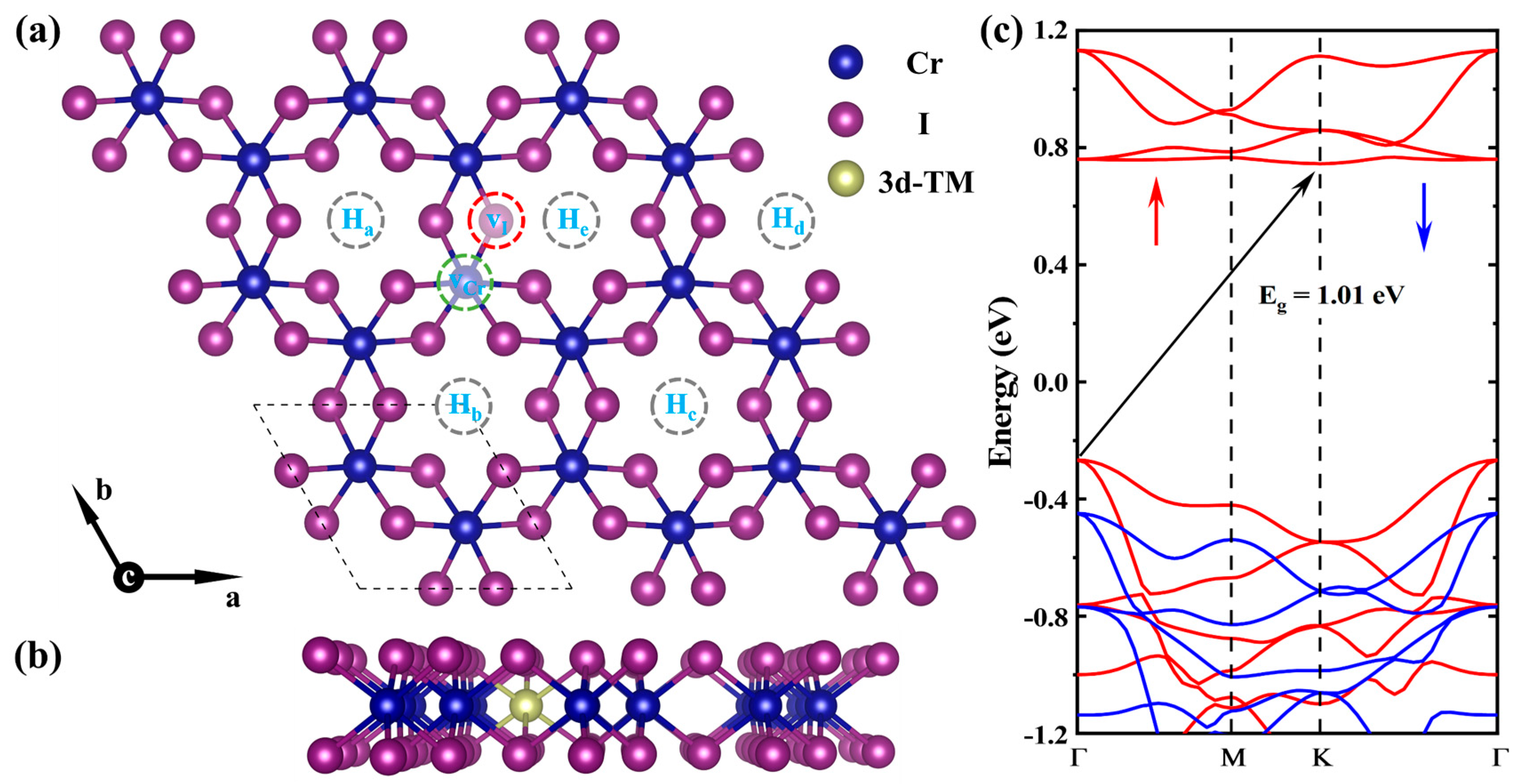
As shown in Figure 1a,b, the monolayer CrI3 is an I-Cr-I sandwiched layer structure. The magnetic Cr3+ ions form a honeycomb network in the octahedral coordination, edge-sharing with six I− ions. The optimized lattice constant of the CrI3 is 7.11 Å, and the bond length between Cr and I atoms is 2.79 Å, which is in good agreement with previous reports [36]. The band gap of monolayer CrI3 at the PBE + U level is 1.01 eV, as shown in Figure 1c, slightly lower than the experimental value of 1.20 eV [37,38].
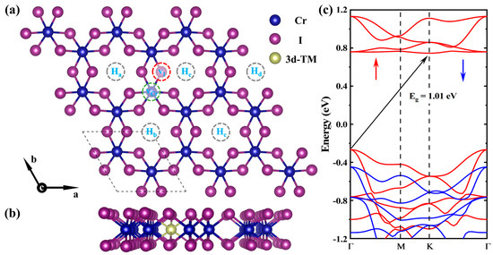
Figure 1.
(a) Top view and (b) side view of the schematic diagram of the intrinsic point defect and impurity 3d-TMs are introduced into the monolayer CrI3 (vI-CrI3, 3d-TMi@CrI3, and 3d-TMi@vI-CrI3). The gray dashed circle indicates TM doping sites, red for I vacancy, and green for Cr vacancy. The lattice constant for the 3 × 3 × 1 CrI3 supercell is a = b = c = 21.35 Å. (c) The band structure of monolayer CrI3 is calculated by PBE + U functional, and the Fermi level is set as 0 eV. The red arrows represent the spin-majority states, and the blue arrows represent the spin-minority states.
Previous studies have demonstrated the susceptibility of monolayer CrI3 to ambient oxidation [39,40,41,42], necessitating the systematic investigation of oxidative stability in vI and 3d-TM co-doped systems. As evidenced by Supplementary Note S3 and Figures S4 and S5, the oxygen-substituted co-doped configurations (TMi@OI-CrI3) exhibit prohibitively high formation energies (~5 eV), confirming their thermodynamic instability. Consequently, our subsequent computational analyses focus exclusively on the magnetic properties of vI-TM co-doped systems.
2.1. The Formation Energy of Point Defect in CrI3
The intrinsic point defects and impurity TMs are introduced into the CrI3 supercells, such as vI-CrI3, vCr-CrI3, 3d-TMi@CrI3, 3d-TMi@vI-CrI3, and 3d-TMi@vCr-CrI3. We exclude the vCr-CrI3 and 3d-TMi@vCr-CrI3 in the following calculations because the formation energy of vCr-CrI3 is significantly higher than that of vI-CrI3, as presented in Figure S6. To verify the favorable doping sites of TMs in the vI-CrI3, we take the Tii@vI-CrI3 as an example and consider five hollow doping sites (Ha, Hb, Hc, Hd, and He, see Figure 1) for the formation energy calculation (see Figure S7). The results show that the formation energies of Tii••@vI-CrI3 systems at the Hb site are lower than those at Ha, Hc, Hd, and He. Hence, we only consider the Hb site to be the doping site in the following calculation of TMi@vI-CrI3.
To investigate different possible charge states under Cr-rich and I-rich conditions, we calculate the defect formation energies of vI-CrI3, 3d-TMi@CrI3, and 3d-TMi@vI-CrI3 for all the possible charge states (−2 to +3) as a function of the Fermi level. Taking vI-CrI3 as an example (see Figure S6), the formation energies of vI-CrI3 in the −2 and −1 charge states are higher than those in the 0 charge state, while the formation energies of vI-CrI3 in the +2 charge state are higher than those in the +1 and 0 charge states. This implies unreasonable charge states have relatively higher formation energies; the charge states we calculated are convergence. Thus, this work only focuses on the charge states that exhibit the lowest formation energy for all investigated systems under Cr-rich and I-rich conditions. The formation energy represents the stability of 3d-TMi@CrI3 and 3d-TMi@vI-CrI3, and small formation energy is desired for the stability, making them even more likely to form [43,44]. As shown in Figures S8 and S9, the solid bold red lines indicate the lowest formation energies at specific Fermi levels. Meanwhile, these formation energies are also summarized in Figure 2, which suggests that 47 types of the TMi@CrI3 and TMi@vI-CrI3 systems under different charge states are stable. Considering the intrinsic point defects vI-CrI3 and (c-d) vCr-CrI3 (Figure S6), there are 49 types of charged systems of vI-CrI3, 3d-TMi@CrI3, and 3d-TMi@vI-CrI3 that are demonstrated to be stable.
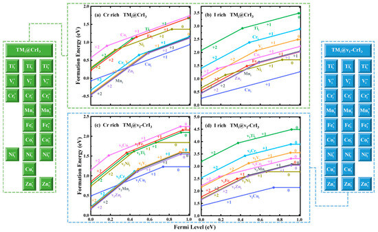
Figure 2.
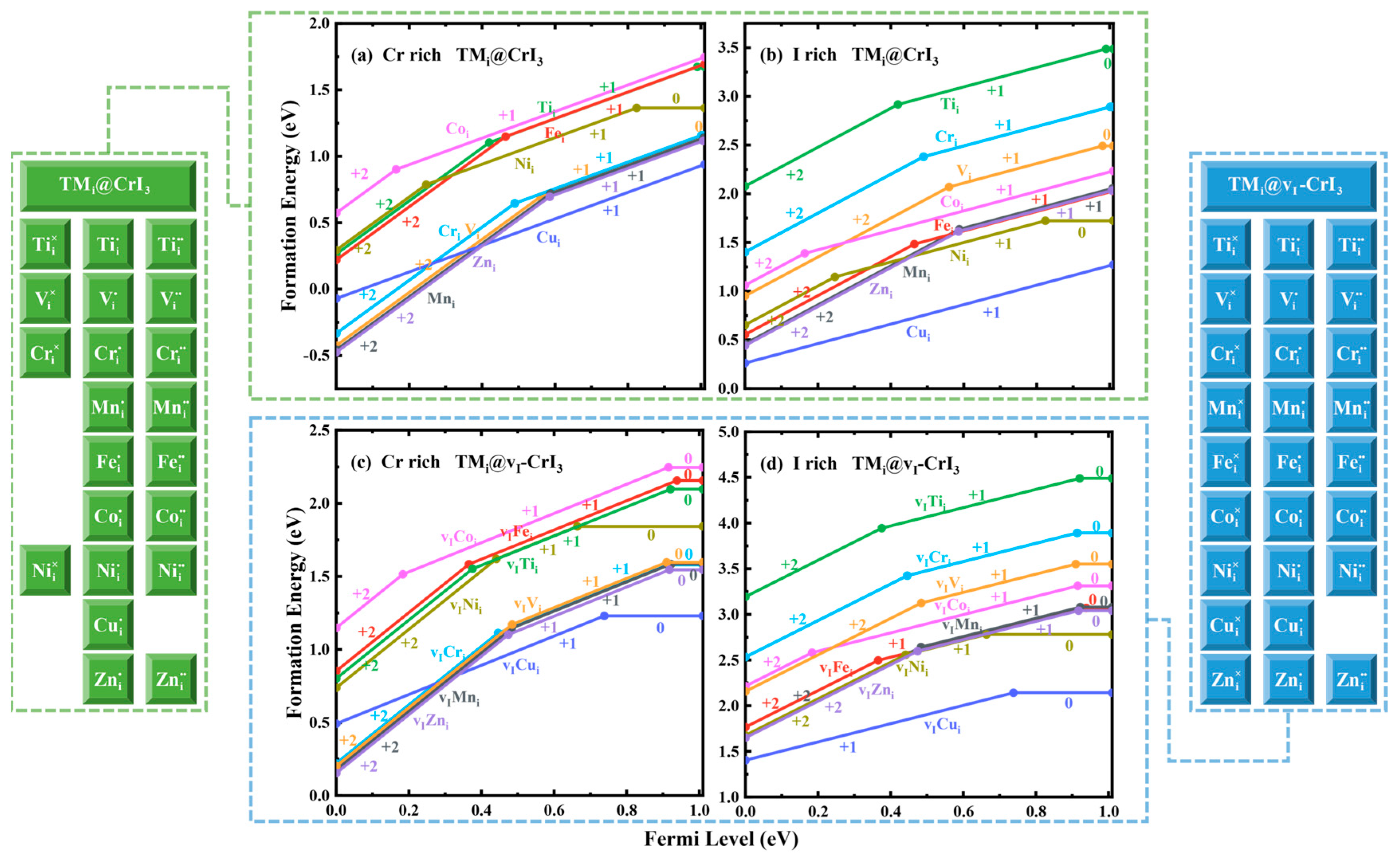
The formation energies of the most favorable charge states of (a,b) TMi@CrI3 and (c,d) TMi@vI-CrI3 systems under Cr-rich and I-rich conditions are plotted as a function of the Fermi level, ranging between the valence band maximum (VBM) and conduction band minimum (CBM). Here, “×”, “•”, and “••” denote the charge states of 0, +1, and +2, respectively.
As illustrated in Figure 2, the formation energy in Cr-rich conditions is low compared to I-rich conditions, indicating that 3d-TMi@CrI3 and 3d-TMi@vI-CrI3 systems are more favorable to form under Cr-rich conditions. Under Cr-rich conditions, compared to Figure 2a,c, we find that the formation energies of 3d-TMi@vI-CrI3 are higher than those of 3d-TMi@CrI3. The same results are found under I-rich conditions, as shown in Figure 2b,d. These results indicate that I vacancies negatively affect the 3d TM doped into the CrI3 monolayer. However, under Cr-rich conditions, the largest formation energies of 3d-TMi@vI-CrI3 are not larger than 2.5eV. Thus, subsequent studies will focus exclusively on the magnetic properties of 3d-TMi@CrI3 and 3d-TMi@vI-CrI3 systems.
As shown in Figure 2a, under Cr-rich conditions, the lowest-formation energy defects are Mni••@CrI3, Zni••@CrI3, and Vi••@CrI3 (their formation energies are almost the same) as EF < 0.40 eV; when EF > 0.40 eV, Cui•@CrI3 is the lowest-formation energy defect. In Figure 2b, the lowest-formation energy defect is Cui•@CrI3 for all the values of the Fermi level under I-rich conditions, making them easier to form. However, the formation energy of Tii@CrI3 is the highest for all the values of the Fermi level, which means it is difficult to dope Ti into the CrI3. For 3d-TMi@vI-CrI3 under Cr-rich conditions (Figure 1c), when EF < 0.34 eV, the lowest-formation energy defects are Mni••@vI-CrI3, Zni••@vI-CrI3, Cri••@vI-CrI3, and Vi••@vI-CrI3 (their formation energies are almost the same); when EF > 0.34 eV, Cui@vI-CrI3 is the lowest-formation energy defect. In Figure 2d, the lowest-formation energy defect is Cui@vI-CrI3 for all the values of the Fermi level under I-rich conditions.
2.2. Magnetic Exchange Interactions
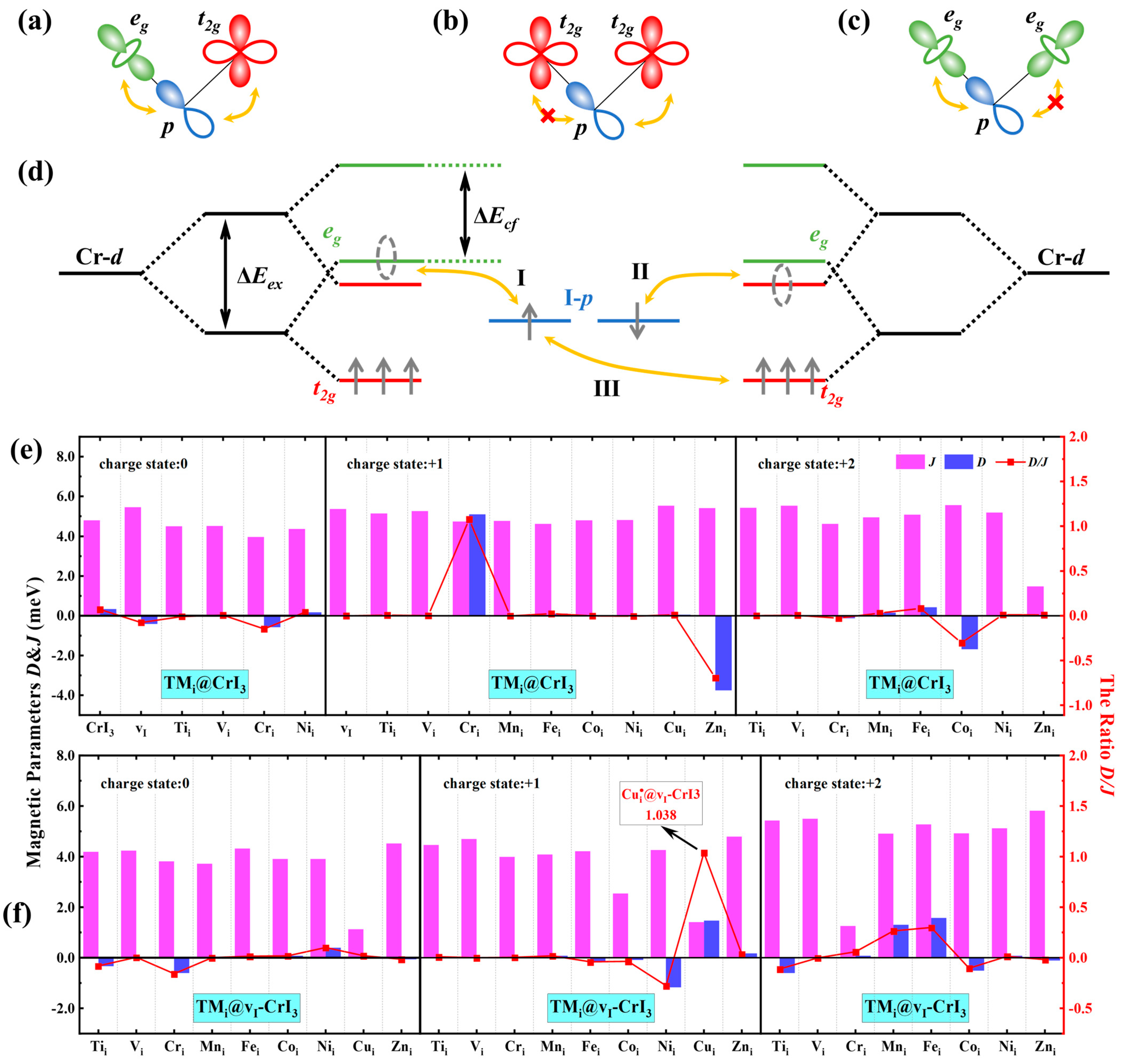
The exchange energies (Eex) of CrI3, 3d-TMi@CrI3, and 3d-TMi@vI-CrI3 are shown in Table S5, to explore the effect of point defects on magnetic properties. The Eex between FM and ferrimagnetic (FiM)/AFM states (Eex = EFM − EFiM/AFM) for all the studied systems are less than 0 eV, indicating that the ferromagnetic state is the ground state. Compared with CrI3, I vacancies and doping with 3d-TMs enhance ferromagnetism. To illustrate the physical origin of ferromagnetic coupling, Figure 3a–d displays the ferromagnetic superexchange mechanism. In a specific octahedral environment, the d levels of Cr atoms split into a higher energy eg doublet, and a lower energy t2g triplet, and three electrons occupy the t2g triplet. In contrast, the eg doublet remains empty in CrI3. Considering that the Cr-I-Cr angle is approximately 90º, a 3d electron in one Cr ion can only transfer to another Cr ion through an eg-p-t2g transition, as shown in Figure 3a. The p orbitals of the I atom strongly overlap with the t2g orbitals of one Cr ion. They are orthogonal to the t2g orbitals of another Cr atom, and thus the t2g-p-t2g transition is forbidden. Similar to t2g-p-t2g transition, there is no simultaneous overlap between the p orbitals and the eg orbitals of both Cr ions in eg-p-eg transition, as shown in Figure 3b–c. Given that the t2g orbitals of the Cr ions are half-occupied while the eg orbitals are empty, according to the Pauli principle, only FM coupling is allowed.
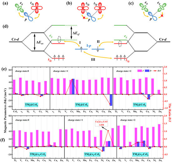
Figure 3.
Ferromagnetic superexchange mechanism. Superexchange channels between two cations via an intermediate anion: (a) eg-p-t2g, (b) t2g-p-t2g, and (c) eg-p-eg. (d) Schematic diagrams of orbital evolution and superexchange interaction. Red, green, and blue bars represent t2g, eg, and p orbitals, respectively. Processes I, II, and III represent the electron hopping between p↑ and eg↑ orbitals, p↓ and t2g↓ orbitals, and p↑ and t2g↑ orbitals, respectively. ΔEex and ΔEcf represent the exchange splitting and crystal field splitting of Cr-d orbitals, respectively. The magnetic exchange parameters D and J, and the ratio of D/J of (e) the CrI3, vI-CrI3, 3d-TMi@CrI3, and (f) 3d-TMi@vI-CrI3 systems under the 0, +1, and +2 charge states (from left to right). A positive D value indicates a tendency for spins to form right-handed helical structures, while a negative D value signifies a tendency for spins to form left-handed helical structures.
We now further discuss the transition process of t2g-p-eg. Two distinct fourth-order electron transfer mechanisms can be sketched, as shown in Figure 3d. The first involves a spin-up electron transferring from the p orbital of an I atom to the eg orbital of one Cr atom, while a spin-down electron simultaneously transfers from the p orbital to the t2g orbital of another Cr atom. Subsequently, both electrons revert back to their original p orbitals (see the hopping processes I and II). The second mechanism is a spin-up electron transferring from the p orbital to the eg orbital of a Cr atom, and then a spin-up electron from the t2g orbital of another Cr atom transferring to the p orbital. Following these transitions, the electrons return to their initial locations in the p and t2g orbitals, respectively (see the hopping processes I and III). As demonstrated in Figure S10, compared to CrI3, the presence of I vacancies and interstitial doping with TMs causes the formation of an impurity band near the Fermi level in the electronic structure, and the reduction of the energy difference between the unoccupied spin-up eg/spin-down t2g orbitals and the p orbitals enhances FM.
Next, we calculate the magnetic exchange parameters J and D between all the nearest-neighbor Cr pairs or Cr-TM pairs, and the Hamiltonian can be written as follows:
where J is the Heisenberg exchange parameter, D is the antisymmetric magnetic exchange parameter, and are spin vectors of Cr atoms and TMs, and is the anisotropy parameter. The J is calculated as and the D is obtained by , where EFM, EFiM/AFM, ECW, and EACW are the energy with FM, FiM/AFM, clockwise (CW), and anticlockwise (ACW) orders in the CrI3, vI-CrI3, TMi@vI-CrI3, and TMi@CrI3 systems, respectively, as shown in Figure S11. The methodology for calculating the J and D is elaborated in Note S4 [45]. A large D/J ratio tends to form a non-collinear magnetic ordering. When D/J exceeds 20%, the system may form stable chiral spin textures, such as skyrmions [46,47,48,49].
Figure 3e,f displays the values of D and J, and the ratios of D/J for the CrI3, vI-CrI3, 3d-TMi@CrI3, and 3d-TMi@vI-CrI3 systems under different charge states, respectively. Compared to CrI3, the values of J in Zni••@CrI3, Cui×@vI-CrI3, Coi•@vI-CrI3, Cui•@vI-CrI3, and Cri••@vI-CrI3 systems significantly decrease. In all the systems, the values of D have a small fluctuation, except those in TMi@CrI3 (TM = Cr and Zn) under the +1 charge state, which have a large enhancement. As a result, the |D|/J values in Cui•@vI-CrI3, Cri•@CrI3, and Zni•@CrI3 are 1.04, 1.07, and 0.69, respectively, which are significantly larger than those in other systems. These values far surpass those of typical materials with skyrmions under appropriate conditions, such as MnSi [50], Cu2OSeO3 [51], and Rh/Fe/Ir [52]. To explore the physical origin of the strong DMI, Figure S12a–d gives the differential charge density of Cui•@vI-CrI3, Zni•@CrI3 by , where and are the charge density of the Cui•@vI-CrI3, Zni•@CrI3, and CrI3 systems, respectively. One can find that the charge distribution between the I-top and I-bottom layers in the system is antisymmetric, which results in a strong DMI.
To further assess the stability of FM in CrI3, vI-CrI3, 3d-TMi@vI-CrI3, and 3d-TMi@CrI3, we calculate the TC using a 5 × 5 × 1 matrix by performing Monte Carlo simulations with the Metropolis algorithm based on the classic Heisenberg model by the MCSOLVER package [53]. As shown in Table S5 and Figure S13, the TC of CrI3 (75 K) is larger than the previously reported value (45 K) [54], which is due to the difference in effective Coulomb interaction correction (Ueff) [55,56]. Compared with CrI3, the TC of Zni••@vI-CrI3 increases to 88 K, indicating that the FM slightly enhanced.
2.3. Magnetic Anisotropy Energy
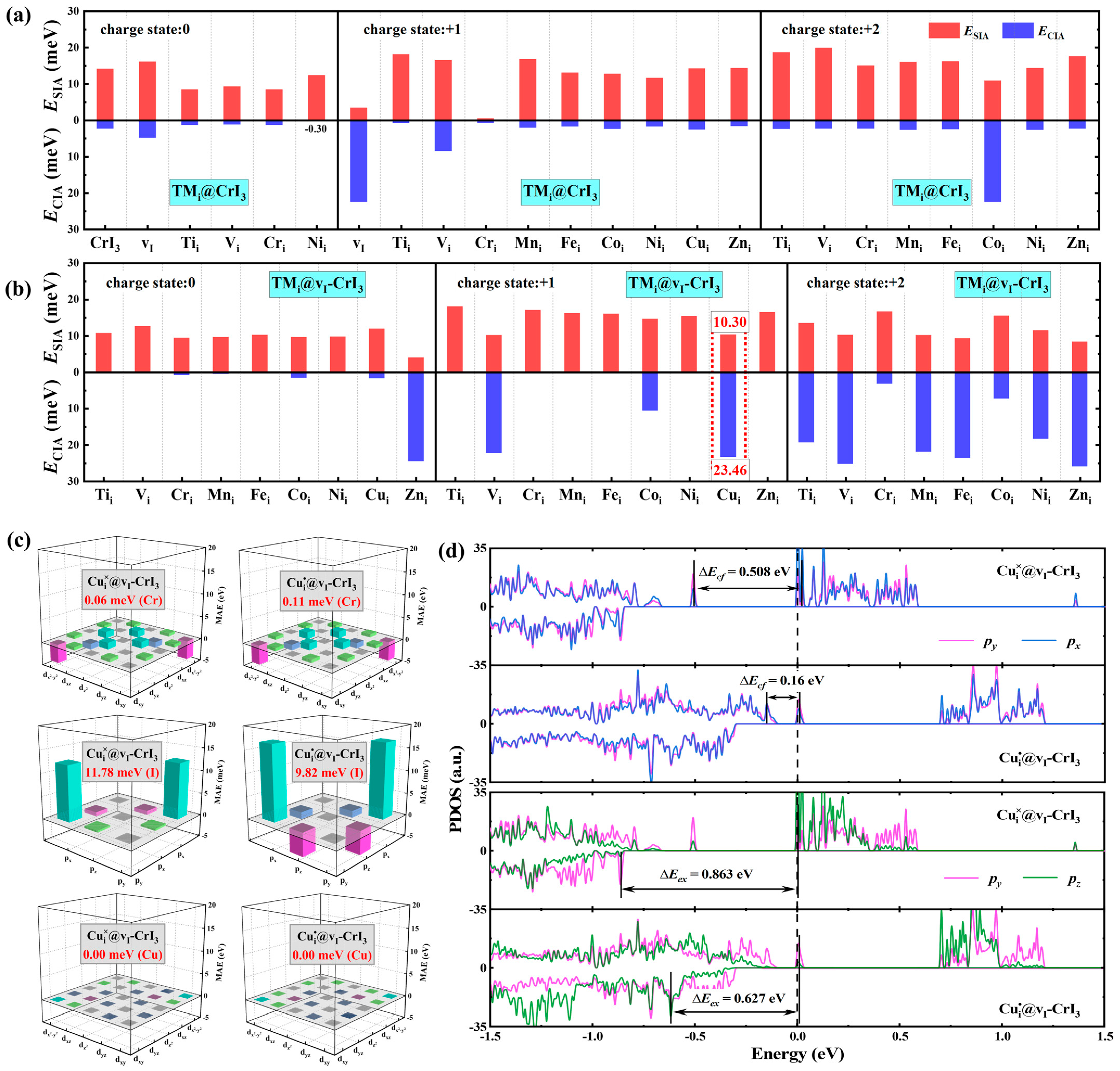
Generally, magnetic anisotropy mainly contains the magnetic shape anisotropy energy (EMSA) resulting from the dipole–dipole interaction and the magnetocrystalline anisotropy energy (EMCA) induced by the spin-orbit coupling (SOC). Compared to EMCA, the values of EMSA are negligible in the CrI3 system [57]. Therefore, in this work, we only consider the impact of MCA. The MCA is primarily contributed by single-ion anisotropy (SIA) [58,59] and covalent interactions anisotropy (CIA) [57,60]. Figure 4a gives the EMCA of the monolayer CrI3, vI-CrI3, TMi@CrI3, and TMi@vI-CrI3 systems under different charge states, respectively. The EMCA of CrI3 is 16.5 meV with an ESIA value of 14.2 meV and an ECIA value of 2.3 meV. This indicates that MCA is mainly derived from the SIA, consistent with previous reports [57,60]. Under neutral charge states, the EMCA values of all the systems are smaller than those of CrI3, except for the Zni×@vI-CrI3 system. Moreover, the EMCA values for most of the systems in positive charge states are higher than those in neutral states, except for the Cri•@CrI3 and Zni•@vI-CrI3 systems. Compared with TMi@CrI3 systems, the EMCA values of TMi@vI-CrI3 systems are large, except for Mni@vI-CrI3 under positive charge states. Considering that Cui@vI-CrI3 system has a large D/J ratio of 1.04 and high uniaxial anisotropy, which can stably enhance the creation of skyrmions [9,10], we subsequently focus on analyzing the origin of EMCA for the Cui@vI-CrI3 system.
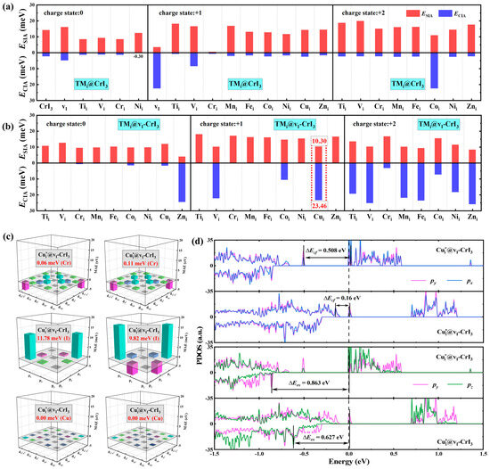
Figure 4.
The values of single-ion anisotropy energy (ESIA) and covalent interactions anisotropy energy (ECIA) of the (a) CrI3, vI-CrI3, 3d-TMi@CrI3, and (b) 3d-TMi@vI-CrI3 systems under the 0, +1, and +2 charge states (from left to right). (c) The orbital-resolved MAE of Cr, I, and Cu atoms in Cui×@vI-CrI3 and Cui•@vI-CrI3 systems, respectively. (d) Partial density of states (PDOS) of py/px and py/px orbitals of I atoms in Cui×@vI-CrI3 and Cui•@vI-CrI3 systems. ΔEcf is crystal field splitting energy, and ΔEex is spin splitting energy.
As shown in Figure 4b, the ESIA of Cui×@vI-CrI3 (11.9 meV) is higher than that of Cui•@vI-CrI3 (10.3 meV). To analyze the charge effect on ESIA, Figure 4c gives the orbital-resolved MAE of Cui@vI-CrI3 systems under 0 and +1 charge states, respectively. It can be observed that the ESIA is primarily contributed by the coupling of py/px and py/pz orbitals for the I atoms under both charge states, while the d orbitals of the Cr and Cu atoms play a minor role. In the neutral charge state, the contribution of py/px and py/pz is positive and leads to an out-of-plane ESIA, while the py/pz orbitals contribute to negative ESIA in the +1 charge state. Compared to the neutral charge state, the contributions of both py/px and py/pz increase in the +1 charge state, and the variation of py/pz orbitals is higher than that of py/px orbitals, which leads to the reduction in the total ESIA.
We now further illuminate the mechanism of the influence of p orbitals of I atoms on the ESIA under 0 and +1 charge states in the Cui@vI-CrI3 system based on second-order perturbation theory. The ESIA can be expressed by the following equation [61]:
where u and o are the energy levels of the unoccupied and occupied states, respectively. ↑ and ↓ denote the spin-up and spin-down states, respectively. Lz and Lx represent the orbital angular momentum components of I atoms. Here, the and are neglected due to the low proportions of spin-up unoccupied states near the Fermi level, as shown in Figure 4d. The differences in the spin-orbital matrix element and their corresponding energy separations determine the ESIA. The relative contributions of the nonzero Lz and Lx matrix elements are , . The other matrix elements of are shown in Table S6.
According to Equations (2) and (3), the ESIA contributed by py/px orbitals originates from the spin-conservation term () in Cui@vI-CrI3, which can be regarded as excitations of electrons from the occupied spin-up state to the unoccupied spin-up state. For the py/pz orbitals, their contributed ESIA comes from the spin-flip term (), which arises from the excitations of electrons from the occupied spin-down state to the unoccupied spin-up state. To better clarify the contribution of py/px and py/pz orbitals coupling to ESIA, we show partial DOS (PDOS) of the I atoms in Figure 4d. The spin-up py/px orbitals contribute to out-of-plane SIA with ΔEcf of 0.508 eV in the Cui×@vI-CrI3 system. Compared to the Cui×@vI-CrI3 system, the Fermi level moves to the low energy side in the Cui•@vI-CrI3 system, and the crystal field splitting energy (ΔEcf) decreases. Therefore, the contribution of coupling py/px orbitals to ESIA increases in the Cui•@vI-CrI3 system. The contribution from py/pz orbitals is small for Cui×@vI-CrI3. The exchange splitting energy (ΔEex) of py/pz orbitals (0.627 eV) for Cui•@vI-CrI3 is smaller than that of Cui×@vI-CrI3 (0.863 eV), increasing the in-plane ESIA. The increase in the positive contribution of py/px is slightly smaller than that of the negative contribution of py/pz, and thus, the overall ESIA decreases as the charge state changes from 0 to +1.
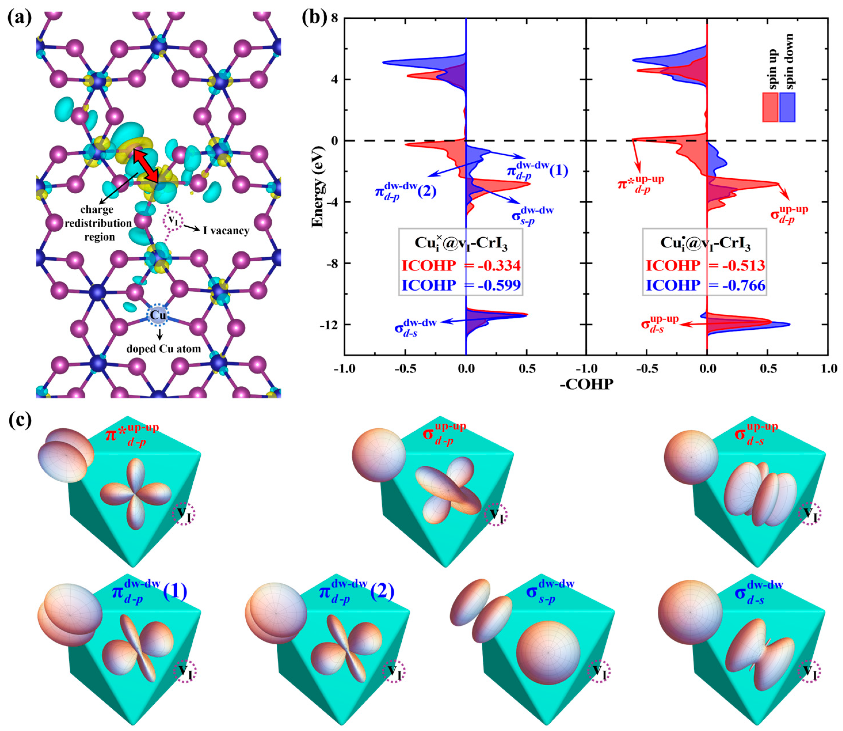
The EMCA of Cui×@vI-CrI3 (13.7 meV) is significantly less than that of Cui•@vI-CrI3 (33.8 meV), whereas the ESIA of both charge states is approximately equal. This is due to the ECIA of Cui•@vI-CrI3 (23.5 meV) being substantially greater than that of Cui×@vI-CrI3 (1.8 meV). To further elucidate the origin of EMCA, we explore ECIA under both charge states. Figure S12a presents the charge density difference of Cui@vI-CrI3 between the +1 and 0 charge states. One can find that the charge redistribution mainly occurs around the I vacancy (See the region indicated by the red arrows in Figure 5a). Then, we calculate the crystal orbital Hamilton population (COHP) to analyze the changes in covalent interaction in the area. As shown in Figure 5b,c, the , , and bonds are formed by the overlap between spin-up Cr atoms and I atoms at −0.25 −2.81 and −11.33 eV, respectively. Among them, the is an antibonding state, mainly formed by the hybridization between the d orbitals of the Cr atoms and the p orbitals of the I atoms. The d and p orbitals are composed of , , , , and py, pz, px with different weights, respectively, as specified in Table S7. Additionally, the and are both bonding states, formed with certain weights by the interaction between the d orbitals of the Cr atoms and the p orbitals and s orbitals of the I atoms, respectively. Similarly, for the spin-down interactions, , , , and are formed at −0.70, −1.20, −3.16, and −11.43 eV, respectively. Notably, all four bonds are bonding states. To describe the covalent strength quantitatively, we calculate the integrated COHP (ICOHP) by integrating the energy up to the Fermi level, where more negative values indicate stronger interactions. As shown in Figure 5b, compared to Cui×@vI-CrI3, the ICOHP of Cui•@vI-CrI3 reduces to −0.513 eV (−0.66 eV) for the spin-up (-down) interactions. This is because the Fermi level moves to the lower energy side, reducing the antibonding state. This indicates that the interaction between spin-up (-down) states from the 0 to the +1 charge state is enhanced, thus leading to the increase in the ECIA in the charge redistribution area. As can be seen from the above analysis, in the Cui@vI-CrI3 system, the EMCA is significantly higher in the +1 charge state than in the 0 charge state, due to the notable increase in the ECIA.
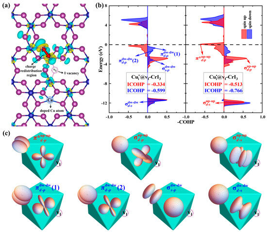
Figure 5.
(a) The charge density difference between Cui×@vI-CrI3 and Cui•@vI-CrI3. The red arrow represents the area of charge redistribution. The yellow and green regions represent electron accumulation and depletion, respectively, and the isosurfaces are set to be 0.0008 e·bohr−3. (b) Projected crystal orbital Hamilton population (COHP) of the Cr-I pair (the region of the arrow in Figure 5a) in Cui×@vI-CrI3 and Cui•@vI-CrI3 systems, respectively. (c) Schematic diagram of the d orbitals of Cr atoms and the p orbitals of nearest neighboring I atoms in an octahedral crystal field. Purple dashed circles indicate I vacancy, and “*” represents antibonding states.
3. Conclusions
In summary, we systematically investigated the effects of defect charge on MAE and DMI of vI-CrI3, 3d-TMi@CrI3, and 3d-TMi@vI-CrI3 (TM = Ti, V, Cr, Mn, Fe, Co, Ni, Cu, and Zn) using DFT calculations. Compared with I-rich conditions, Cr-rich conditions are more favorable for the formation of these systems. Among these systems, the MAEs of Coi••@CrI3, 3d-TMi•@vI-CrI3 (TM = V and Cu), and 3d-TMi••@vI-CrI3 (TM = Ti, V, Mn, Fe, and Zn) all exceed 30 meV. This is derived from the change in the coupling of py/px orbitals for I atoms near the Fermi level under different charge states. Notably, the D/J ratio of Cui•@vI-CrI3 exceeds 1 due to the electrostatic potential differences between the I-top and I-bottom layers, which are conducive to forming stable chiral spin textures. Moreover, I vacancies and TMs enhance the ferromagnetic stability of CrI3 due to an impurity band near the Fermi level, which reduces the energy difference between the unoccupied spin-up eg/spin-down t2g orbitals and the p orbitals. This study provides new possibilities for controlling the MAE and DMI by defect charge states in 2D magnetic materials.
4. Computational Details
All the DFT calculations were performed using the projected augmented wave [62] approach, as implemented in the Vienna ab initio simulation (VASP) [63,64]. Considering the exchange and correlation functional interactions, the Perdew–Burke–Ernzerhof (PBE) within generalized gradient approximation was applied [65]. The plane wave cut-off energy was set to 500 eV. The crystal structure of the monolayer CrI3 was completely relaxed until a force of less than 0.02 eV/Å per atom and an energy difference of smaller than 10−7 eV between two convergence steps was observed. The VASPKIT code was applied for postprocessing VASP-calculated data [66]. In addition, the crystal orbital Hamilton population (COHP) analysis was carried out to quantify the strength (the integrated value of COHP, ICOHP) of the Cr-I bond using the LOBSTER code [67]. The figures were visualized using VESTA [68]. Partly occupied d orbitals of the TMs were treated using the GGA + U approach. The methodology for calculating the Ueff of defect systems is elaborated in Supplementary Note S1 [26,36,37,69,70,71,72], and Figures S1 and S2. The Ueff of impurity-related phases used for the PBE functional calculations are summarized in Table S1. The calculating methodology for the formation energy of defects is provided in Note S2 [35,73,74,75,76,77,78,79,80,81,82,83,84,85,86,87,88,89,90,91] and Figure S3. The lattice constants used in the calculations from experimental data are listed in Table S2 [92,93,94,95,96,97,98,99,100,101]. Table S3 presents the formation enthalpy for these impurity-related phases. The chemical potential obtained in this work is displayed in Table S4. We used the standard Kröger–Vink notation [102] (XDq) to represent the defect charge state q (′, ×, • being −1, 0, and +1 charge state, respectively) and lattice site D of a dopant X.
Magnetocrystalline anisotropy (MCA) is calculated by taking the difference between the total energy of the magnetization oriented along the in-plane () and out-of-plane () directions, as follows:
A positive value represents uniaxial or perpendicular anisotropy, which means the easy magnetization axis is perpendicular to the x-y plane, i.e., along the z-axis. In contrast, a negative represents planar anisotropy, which suggests the easy magnetization axis is parallel to the x-y plane.
Supplementary Materials
The following supporting information can be downloaded at https://www.mdpi.com/article/10.3390/condmat10020029/s1, The Ueff parameters for TMs, chemical potentials, and formation energies as a function of the Fermi level, calculating magnetic exchange parameters J and D though FM, FiM, CW, and ACW spin configurations in vI-CrI3, TMi@vI-CrI3, and TMi@CrI3 systems; the doping sites of TMs in TMi@vI-CrI3; the DOS in all systems under different charge states; the charge density difference in Cui@vI-CrI3 and Zni@CrI3.
Author Contributions
Conceptualization, G.G. and W.W.; methodology, G.J., Q.Y., G.G. and W.W.; software, G.J., K.Z., W.W. and J.Y.; validation, W.W., G.J. and G.G.; formal analysis, G.G., W.W. and G.J.; investigation, G.J. and W.W.; resources, G.G. and J.Y.; data curation, G.J., W.W. and K.Z.; writing—original draft preparation, G.J.; writing—review and editing, G.J., W.W. and G.G.; visualization, G.J., Q.Y., K.Z. and W.W.; supervision, W.W. and G.G.; project administration, W.W. and G.G.; funding acquisition, G.G. All authors have read and agreed to the published version of the manuscript.
Funding
We acknowledge the financial support from the National Natural Science Foundation of China (Grant No. 12064036, 11764034, and 11464038). The work was carried out at Shanxi Supercomputing Center of China, and the calculations were performed on TianHe-2. This research is also supported by the advanced computing resources provided by the Supercomputing Center of the USTC.
Data Availability Statement
All data are already included in the main text and the Supplementary Materials.
Conflicts of Interest
The authors declare no conflict of interest.
References
- Xing, S.; Zhou, J.; Zhang, X.; Elliott, S.; Sun, Z. Theory, properties and engineering of 2D magnetic materials. Prog. Mater Sci. 2023, 132, 101036. [Google Scholar] [CrossRef]
- Chen, B.; Zeng, M.; Khoo, K.H.; Das, D.; Fong, X.; Fukami, S.; Li, S.; Zhao, W.; Parkin, S.S.P.; Piramanayagam, S.N.; et al. Spintronic devices for high-density memory and neuromorphic computing—A review. Mater. Today 2023, 70, 193–217. [Google Scholar] [CrossRef]
- Zhang, Y.; Feng, X.; Zheng, Z.; Zhang, Z.; Lin, K.; Sun, X.; Wang, G.; Wang, J.; Wei, J.; Vallobra, P.; et al. Ferrimagnets for spintronic devices: From materials to applications. Appl. Phys. Rev. 2023, 10, 011301. [Google Scholar] [CrossRef]
- Gibertini, M.; Koperski, M.; Morpurgo, A.F.; Novoselov, K.S. Magnetic 2D materials and heterostructures. Nat. Nanotechnol. 2019, 14, 408–419. [Google Scholar] [CrossRef]
- Yang, F.; Hu, P.; Yang, F.F.; Chen, B.; Yin, F.; Sun, R.; Hao, K.; Zhu, F.; Wang, K.; Yin, Z. Emerging enhancement and regulation strategies for ferromagnetic 2D transition metal dichalcogenides. Adv. Sci. 2023, 10, 2300952. [Google Scholar] [CrossRef]
- Wang, Z.; Yin, Z.; Gao, Y.; Wang, H.; Gao, J.; Zhao, J. Selecting dual atomic clusters supported on two-dimensional biphenylene with significantly optimized capability to reduce carbon monoxide. J. Mater. Chem. A 2024, 12, 2748–2759. [Google Scholar] [CrossRef]
- Bijker, R. Phase transitions and spontaneously broken symmetries. Fundam. Phys. 2009, 3, 51–60. [Google Scholar]
- Mermin, N.D.; Wagner, H. Absence of ferromagnetism or antiferromagnetism in one-or two-dimensional isotropic Heisenberg models. Phys. Rev. Lett. 1966, 17, 1133. [Google Scholar] [CrossRef]
- Wilson, M.N.; Butenko, A.; Bogdanov, A.; Monchesky, T. Chiral skyrmions in cubic helimagnet films: The role of uniaxial anisotropy. Phys. Rev. B 2014, 89, 094411. [Google Scholar] [CrossRef]
- Butenko, A.; Leonov, A.; Rößler, U.; Bogdanov, A. Stabilization of skyrmion textures by uniaxial distortions in noncentrosymmetric cubic helimagnets. Phys. Rev. B 2010, 82, 052403. [Google Scholar] [CrossRef]
- Tokura, Y.; Kanazawa, N. Magnetic Skyrmion Materials. Chem. Rev. 2021, 121, 2857–2897. [Google Scholar] [CrossRef] [PubMed]
- Kong, L.; Bo, L.; Zhao, R.; Hu, C.; Ji, L.; Chen, W.; Li, Y.; Zhang, Y.; Zhang, X. The modes of skyrmionium motion induced by vacancy defects on a racetrack. J. Magn. Magn. Mater. 2021, 537, 168173. [Google Scholar] [CrossRef]
- Smiri, A.; Jaziri, S.; Lounis, S.; Gerber, I.C. DFT+ U investigation of magnetocrystalline anisotropy of Mn-doped transition-metal dichalcogenide monolayers. Phys. Rev. Mater. 2021, 5, 054001. [Google Scholar] [CrossRef]
- Langer, R.; Mustonen, K.; Markevich, A.; Otyepka, M.; Susi, T.; Błoński, P. Graphene Lattices with Embedded Transition-Metal Atoms and Tunable Magnetic Anisotropy Energy: Implications for Spintronic Devices. ACS Appl. Nano Mater. 2022, 5, 1562–1573. [Google Scholar] [CrossRef]
- Zheng, G.; Wang, M.; Zhu, X.; Tan, C.; Wang, J.; Albarakati, S.; Aloufi, N.; Algarni, M.; Farrar, L.; Wu, M.; et al. Tailoring Dzyaloshinskii–Moriya interaction in a transition metal dichalcogenide by dual-intercalation. Nat. Commun. 2021, 12, 3639. [Google Scholar] [CrossRef]
- Banik, S.; Chattopadhyay, M.K.; Tripathi, S.; Rawat, R.; Jha, S.N. Large positive magnetoresistance and Dzyaloshinskii–Moriya interaction in CrSi driven by Cr 3d localization. Sci. Rep. 2020, 10, 12030. [Google Scholar] [CrossRef]
- Huang, B.; Clark, G.; Navarro-Moratalla, E.; Klein, D.R.; Cheng, R.; Seyler, K.L.; Zhong, D.; Schmidgall, E.; McGuire, M.A.; Cobden, D.H.; et al. Layer-dependent ferromagnetism in a van der Waals crystal down to the monolayer limit. Nature 2017, 546, 270–273. [Google Scholar] [CrossRef]
- Soriano, D.; Katsnelson, M.I.; Fernández-Rossier, J. Magnetic Two-Dimensional Chromium Trihalides: A Theoretical Perspective. Nano Lett. 2020, 20, 6225–6234. [Google Scholar] [CrossRef]
- Song, T.; Cai, X.; Tu, M.W.-Y.; Zhang, X.; Huang, B.; Wilson, N.P.; Seyler, K.L.; Zhu, L.; Taniguchi, T.; Watanabe, K.; et al. Giant tunneling magnetoresistance in spin-filter van der Waals heterostructures. Science 2018, 360, 1214–1218. [Google Scholar] [CrossRef]
- Lee, Y.C.; Chang, S.W.; Chen, S.H.; Chen, S.L.; Chen, H.L. Optical Inspection of 2D Materials: From Mechanical Exfoliation to Wafer-Scale Growth and Beyond. Adv. Sci. 2022, 9, 2102128. [Google Scholar] [CrossRef]
- Islam, M.A.; Serles, P.; Kumral, B.; Demingos, P.G.; Qureshi, T.; Meiyazhagan, A.; Puthirath, A.B.; Abdullah, M.S.B.; Faysal, S.R.; Ajayan, P.M.; et al. Exfoliation mechanisms of 2D materials and their applications. Appl. Phys. Rev. 2022, 9, 041301. [Google Scholar] [CrossRef]
- Yi, M.; Shen, Z. A review on mechanical exfoliation for the scalable production of graphene. J. Mater. Chem. A 2015, 3, 11700–11715. [Google Scholar] [CrossRef]
- Zhang, J.; Guo, Y.; Li, P.; Wang, J.; Zhou, S.; Zhao, J.; Guo, D.; Zhong, D. Imaging Vacancy Defects in Single-Layer Chromium Triiodide. J. Phys. Chem. Lett. 2021, 12, 2199–2205. [Google Scholar] [CrossRef] [PubMed]
- Pan, S.; Bai, Y.; Tang, J.; Wang, P.; You, Y.; Xu, G.; Xu, F. Growth of high-quality CrI3 single crystals and engineering of its magnetic properties via V and Mn doping. J. Alloys Compd. 2022, 908, 164573. [Google Scholar] [CrossRef]
- Thiel, L.; Wang, Z.; Tschudin, M.A.; Rohner, D.; Gutiérrez-Lezama, I.; Ubrig, N.; Gibertini, M.; Giannini, E.; Morpurgo, A.F.; Maletinsky, P. Probing magnetism in 2D materials at the nanoscale with single-spin microscopy. Science 2019, 364, 973–976. [Google Scholar] [CrossRef]
- Wang, R.; Su, Y.; Yang, G.; Zhang, J.; Zhang, S. Bipolar doping by intrinsic defects and magnetic phase instability in monolayer CrI3. Chem. Mater. 2020, 32, 1545–1552. [Google Scholar] [CrossRef]
- Yang, Q.; Hu, X.; Shen, X.; Krasheninnikov, A.V.; Chen, Z.; Sun, L. Enhancing Ferromagnetism and Tuning Electronic Properties of CrI3 Monolayers by Adsorption of Transition-Metal Atoms. ACS Appl. Mater. Interfaces 2021, 13, 21593–21601. [Google Scholar] [CrossRef]
- Pizzochero, M. Atomic-scale defects in the two-dimensional ferromagnet CrI3 from first principles. J. Phys. D Appl. Phys. 2020, 53, 244003. [Google Scholar] [CrossRef]
- Guo, Y.; Yuan, S.; Wang, B.; Shi, L.; Wang, J. Half-metallicity and enhanced ferromagnetism in Li-adsorbed ultrathin chromium triiodide. J. Mater. Chem. C 2018, 6, 5716–5720. [Google Scholar] [CrossRef]
- Zhao, Y.; Lin, L.; Zhou, Q.; Li, Y.; Yuan, S.; Chen, Q.; Dong, S.; Wang, J. Surface Vacancy-Induced Switchable Electric Polarization and Enhanced Ferromagnetism in Monolayer Metal Trihalides. Nano Lett. 2018, 18, 2943–2949. [Google Scholar] [CrossRef]
- Zhang, J.-M.; Zhu, W.; Zhang, Y.; Xiao, D.; Yao, Y. Tailoring magnetic doping in the topological insulator Bi2Se3. Phys. Rev. Lett. 2012, 109, 266405. [Google Scholar] [CrossRef] [PubMed]
- Li, D.; Zhang, A.; Feng, Z.; Wang, W. Theoretical Insights on the Charge State and Bifunctional OER/ORR Electrocatalyst Activity in 4d-Transition-Metal-Doped g-C3N4 Monolayers. ACS Appl. Mater. Interfaces 2024. [Google Scholar] [CrossRef] [PubMed]
- Yue, S.; Li, D.; Zhang, A.; Yan, Y.; Yan, H.; Feng, Z.; Wang, W. Rational design of single transition-metal atoms anchored on a PtSe2 monolayer as bifunctional OER/ORR electrocatalysts: A defect chemistry and machine learning study. J. Mater. Chem. A 2024, 12, 5451–5463. [Google Scholar] [CrossRef]
- Xu, H.; Li, D.; Deng, M.; Liu, X.; Feng, Z.; Wang, W. Intrinsic point defects and the n-type dopability of Bi2MoO6 with higher photocatalytic performance: A hybrid functional study. Phys. Rev. Mater. 2023, 7, 045401. [Google Scholar] [CrossRef]
- Kuklin, A.V.; Begunovich, L.V.; Gao, L.; Zhang, H.; Ågren, H. Point and complex defects in monolayer PdSe2: Evolution of electronic structure and emergence of magnetism. Phys. Rev. B 2021, 104, 134109. [Google Scholar] [CrossRef]
- Chen, S.; Huang, C.; Sun, H.; Ding, J.; Jena, P.; Kan, E. Boosting the Curie temperature of two-dimensional semiconducting CrI3 monolayer through van der Waals heterostructures. J. Phys. Chem. C 2019, 123, 17987–17993. [Google Scholar] [CrossRef]
- McGuire, M.A.; Dixit, H.; Cooper, V.R.; Sales, B.C. Coupling of crystal structure and magnetism in the layered, ferromagnetic insulator CrI3. Chem. Mater. 2015, 27, 612–620. [Google Scholar] [CrossRef]
- Dillon Jr, J.; Olson, C. Magnetization, resonance, and optical properties of the ferromagnet CrI3. J. Appl. Phys. 1965, 36, 1259–1260. [Google Scholar] [CrossRef]
- Zhang, T.; Grzeszczyk, M.; Li, J.; Yu, W.; Xu, H.; He, P.; Yang, L.; Qiu, Z.; Lin, H.; Yang, H. Degradation chemistry and kinetic stabilization of magnetic CrI3. J. Am. Chem. Soc. 2022, 144, 5295–5303. [Google Scholar] [CrossRef]
- Kazim, S.; Mastrippolito, D.; Moras, P.; Jugovac, M.; Klimczuk, T.; Ali, M.; Ottaviano, L.; Gunnella, R. Synchrotron radiation photoemission spectroscopy of the oxygen modified CrCl3 surface. Phys. Chem. Chem. Phys. 2023, 25, 3806–3814. [Google Scholar] [CrossRef]
- Wu, Y.; Zhu, M.; Zhao, R.; Liu, X.; Shen, J.; Huang, H.; Shen, S.; Zhang, L.; Zhang, J.; Zheng, X. Degradation effect and magnetoelectric transport properties in CrBr3 devices. Materials 2022, 15, 3007. [Google Scholar] [CrossRef] [PubMed]
- Mastrippolito, D.; Swiatek, H.; Moras, P.; Jugovac, M.; Gunnella, R.; Lozzi, L.; Benassi, P.; Klimczuk, T.; Ottaviano, L. Intense and stable room-temperature photoluminescence from nanoporous vanadium oxide formed by in-ambient degradation of VI3 crystals. J. Lumin. 2022, 251, 119137. [Google Scholar] [CrossRef]
- Hine, N.; Frensch, K.; Foulkes, W.; Finnis, M. Supercell size scaling of density functional theory formation energies of charged defects. Phys. Rev. B 2009, 79, 024112. [Google Scholar] [CrossRef]
- Hu, W.; Zhang, L. High-throughput calculation and machine learning of two-dimensional halide perovskite materials: Formation energy and band gap. Mater. Today Commu. 2023, 35, 105841. [Google Scholar] [CrossRef]
- Moriya, T. Anisotropic superexchange interaction and weak ferromagnetism. Phys. Rev. 1960, 120, 91. [Google Scholar] [CrossRef]
- Dou, K.; He, Z.; Du, W.; Dai, Y.; Huang, B.; Ma, Y. d0 Magnetic Skyrmions in Two-Dimensional Lattice. Adv. Funct. Mater. 2023, 33, 2301817. [Google Scholar] [CrossRef]
- Chen, T.; Guo, C.; Sengupta, P.; Poletti, D. Effects of staggered Dzyaloshinskii-Moriya interactions in a quasi-two-dimensional Shastry-Sutherland model. Phys. Rev. B 2020, 101, 064417. [Google Scholar] [CrossRef]
- Du, W.; Dou, K.; He, Z.; Dai, Y.; Huang, B.; Ma, Y. Spontaneous magnetic skyrmions in single-layer CrInX3 (X = Te, Se). Nano Lett. 2022, 22, 3440–3446. [Google Scholar] [CrossRef]
- Luo, H.-B.; Zhang, H.-B.; Liu, J.P. Strong hopping induced Dzyaloshinskii–Moriya interaction and skyrmions in elemental cobalt. npj Comput. Mater. 2019, 5, 50. [Google Scholar] [CrossRef]
- Shanavas, K.; Satpathy, S. Electronic structure and the origin of the Dzyaloshinskii-Moriya interaction in MnSi. Phys. Rev. B 2016, 93, 195101. [Google Scholar] [CrossRef]
- Janson, O.; Rousochatzakis, I.; Tsirlin, A.A.; Belesi, M.; Leonov, A.A.; Rößler, U.K.; Van Den Brink, J.; Rosner, H. The quantum nature of skyrmions and half-skyrmions in Cu2OSeO3. Nat. Commun. 2014, 5, 5376. [Google Scholar] [CrossRef] [PubMed]
- Romming, N.; Pralow, H.; Kubetzka, A.; Hoffmann, M.; von Malottki, S.; Meyer, S.; Dupé, B.; Wiesendanger, R.; von Bergmann, K.; Heinze, S. Competition of Dzyaloshinskii-Moriya and higher-order exchange interactions in Rh/Fe atomic bilayers on Ir (111). Phys. Rev. Lett. 2018, 120, 207201. [Google Scholar] [CrossRef] [PubMed]
- Liu, L.; Ren, X.; Xie, J.; Cheng, B.; Liu, W.; An, T.; Qin, H.; Hu, J. Magnetic switches via electric field in BN nanoribbons. Appl. Surf. Sci. 2019, 480, 300–307. [Google Scholar] [CrossRef]
- Gong, C.; Li, L.; Li, Z.; Ji, H.; Stern, A.; Xia, Y.; Cao, T.; Bao, W.; Wang, C.; Wang, Y.; et al. Discovery of intrinsic ferromagnetism in two-dimensional van der Waals crystals. Nature 2017, 546, 265–269. [Google Scholar] [CrossRef]
- Lang, N.D.; Ehrenreich, H. Pressure Dependence of Curie Temperature in Ni. J. Appl. Phys. 1967, 38, 1316–1318. [Google Scholar] [CrossRef]
- Yekta, Y.; Hadipour, H.; Şaşıoğlu, E.; Friedrich, C.; Jafari, S.A.; Blügel, S.; Mertig, I. Strength of effective Coulomb interaction in two-dimensional transition-metal halides MX2 and MX3 (M = Ti, V, Cr, Mn, Fe, Co, Ni; X = Cl, Br, I). Phys. Rev. Mater. 2021, 5, 034001. [Google Scholar] [CrossRef]
- Kim, D.-H.; Kim, K.; Ko, K.-T.; Seo, J.; Kim, J.S.; Jang, T.-H.; Kim, Y.; Kim, J.-Y.; Cheong, S.-W.; Park, J.-H. Giant Magnetic Anisotropy Induced by Ligand L S Coupling in Layered Cr Compounds. Phys. Rev. Lett. 2019, 122, 207201. [Google Scholar] [CrossRef]
- Lu, X.; Fei, R.; Zhu, L.; Yang, L. Meron-like topological spin defects in monolayer CrCl3. Nat. Commun. 2020, 11, 4724. [Google Scholar] [CrossRef]
- Xu, C.; Feng, J.; Xiang, H.; Bellaiche, L. Interplay between Kitaev interaction and single ion anisotropy in ferromagnetic CrI3 and CrGeTe3 monolayers. npj Comput. Mater. 2018, 4, 57. [Google Scholar] [CrossRef]
- Lado, J.L.; Fernández-Rossier, J. On the origin of magnetic anisotropy in two dimensional CrI3. 2D Mater. 2017, 4, 035002. [Google Scholar] [CrossRef]
- Wang, D.-s.; Wu, R.; Freeman, A. First-principles theory of surface magnetocrystalline anisotropy and the diatomic-pair model. Phys. Rev. B 1993, 47, 14932. [Google Scholar] [CrossRef] [PubMed]
- Blöchl, P.E. Projector augmented-wave method. Phys. Rev. B 1994, 50, 17953–17979. [Google Scholar] [CrossRef] [PubMed]
- Kresse, G.; Hafner, J. Ab initio molecular dynamics for liquid metals. Phys. Rev. B 1993, 47, 558–561. [Google Scholar] [CrossRef] [PubMed]
- Kresse, G.; Furthmuller, J. Efficient iterative schemes for ab initio total-energy calculations using a plane-wave basis set. Phys. Rev. B 1996, 54, 11169–11186. [Google Scholar] [CrossRef]
- Perdew, J.P.; Burke, K.; Ernzerhof, M. Generalized gradient approximation made simple. Phys. Rev. Lett. 1996, 77, 3865. [Google Scholar] [CrossRef]
- Wang, V.; Xu, N.; Liu, J.-C.; Tang, G.; Geng, W.-T. VASPKIT: A user-friendly interface facilitating high-throughput computing and analysis using VASP code. Comput. Phys. Commun. 2021, 267, 108033. [Google Scholar] [CrossRef]
- Dronskowski, R.; Bloechl, P.E. Crystal orbital Hamilton populations (COHP): Energy-resolved visualization of chemical bonding in solids based on density-functional calculations. J. Phys. Chem. 1993, 97, 8617–8624. [Google Scholar] [CrossRef]
- Momma, K.; Izumi, F. VESTA 3 for three-dimensional visualization of crystal, volumetric and morphology data. J. Appl. Crystallogr. 2011, 44, 1272–1276. [Google Scholar] [CrossRef]
- Cococcioni, M.; De Gironcoli, S. Linear response approach to the calculation of the effective interaction parameters in the LDA + U method. Phys. Rev. B 2005, 71, 035105. [Google Scholar] [CrossRef]
- Webster, L.; Yan, J.-A. Strain-tunable magnetic anisotropy in monolayer CrCl3, CrBr3, and CrI3. Phys. Rev. B 2018, 98, 144411. [Google Scholar] [CrossRef]
- Jiang, P.; Li, L.; Liao, Z.; Zhao, Y.; Zhong, Z. Spin direction-controlled electronic band structure in two-dimensional ferromagnetic CrI3. Nano Lett. 2018, 18, 3844–3849. [Google Scholar] [CrossRef] [PubMed]
- Zhang, F.; Mi, W.; Wang, X. Spin-dependent electronic structure and magnetic anisotropy of 2D ferromagnetic Janus Cr2I3X3 (X = Br, Cl) monolayers. Adv. Electron. Mater. 2020, 6, 1900778. [Google Scholar] [CrossRef]
- Van de Walle, C.G.; Neugebauer, J. First-principles calculations for defects and impurities: Applications to III-nitrides. J. Appl. Phys. 2004, 95, 3851–3879. [Google Scholar] [CrossRef]
- Vasyutinskii, B.; Kartmazov, G.; Finkel, V. Problems of the structure of chromium at temperatures of 700–1700 C. Fiz. Met. Metalloved. 1961, 12, 141–142. [Google Scholar]
- Shimomura, C.; Takemura, K.; Fujii, Y.; Minomura, S.; Mori, M.; Noda, Y.; Yamada, Y. Structure analysis of high-pressure metallic state of iodine. Phys. Rev. B 1978, 18, 715. [Google Scholar] [CrossRef]
- Yin, W.-J.; Wei, S.-H.; Al-Jassim, M.M.; Turner, J.; Yan, Y. Doping properties of monoclinic BiVO4 studied by first-principles density-functional theory. Phys. Rev. B 2011, 83, 155102. [Google Scholar] [CrossRef]
- Zhang, J.; Chen, X.; Deng, M.; Shen, H.; Li, H.; Ding, J. Effects of native defects and cerium impurity on the monoclinic BiVO4 photocatalyst obtained via PBE + U calculations. Phys. Chem. Chem. Phys. 2020, 22, 25297–25305. [Google Scholar] [CrossRef]
- Zhang, J.; Deng, P.; Deng, M.; Shen, H.; Feng, Z.; Li, H. Hybrid density functional theory study of native defects and nonmetal (C, N, S, and P) doping in a Bi2WO6 photocatalyst. ACS Omega 2020, 5, 29081–29091. [Google Scholar] [CrossRef]
- Kirklin, S.; Saal, J.E.; Meredig, B.; Thompson, A.; Doak, J.W.; Aykol, M.; Rühl, S.; Wolverton, C. The Open Quantum Materials Database (OQMD): Assessing the accuracy of DFT formation energies. npj Comput. Mater. 2015, 1, 15010. [Google Scholar] [CrossRef]
- Saal, J.E.; Kirklin, S.; Aykol, M.; Meredig, B.; Wolverton, C. Materials design and discovery with high-throughput density functional theory: The open quantum materials database (OQMD). JOM 2013, 65, 1501–1509. [Google Scholar] [CrossRef]
- Lany, S.; Zunger, A. Assessment of correction methods for the band-gap problem and for finite-size effects in supercell defect calculations: Case studies for ZnO and GaAs. Phys. Rev. B 2008, 78, 235104. [Google Scholar] [CrossRef]
- Komsa, H.-P.; Pasquarello, A. Finite-size supercell correction for charged defects at surfaces and interfaces. Phys. Rev. Lett. 2013, 110, 095505. [Google Scholar] [CrossRef] [PubMed]
- Komsa, H.-P.; Berseneva, N.; Krasheninnikov, A.V.; Nieminen, R.M. Charged point defects in the flatland: Accurate formation energy calculations in two-dimensional materials. Phys. Rev. X 2014, 4, 031044. [Google Scholar] [CrossRef]
- Singh, A.; Singh, A.K. Atypical behavior of intrinsic defects and promising dopants in two-dimensional WS2. Phys. Rev. Mater. 2021, 5, 084001. [Google Scholar] [CrossRef]
- Singh, A.; Singh, A.K. Origin of n-type conductivity of monolayer MoS2. Phys. Rev. B 2019, 99, 121201. [Google Scholar] [CrossRef]
- Manjanath, A.; Hsu, C.-P.; Kawazoe, Y. Tuning the electronic and magnetic properties of pentagraphene through the C1 vacancy. 2D Mater. 2020, 7, 045024. [Google Scholar] [CrossRef]
- Singh, A.; Manjanath, A.; Singh, A.K. Engineering defect transition-levels through the van der Waals heterostructure. J. Phys. Chem. C 2018, 122, 24475–24480. [Google Scholar] [CrossRef]
- Noh, J.-Y.; Kim, H.; Kim, Y.-S. Stability and electronic structures of native defects in single-layer MoS2. Phys. Rev. B 2014, 89, 205417. [Google Scholar] [CrossRef]
- Zhang, J.; Li, D.; Ju, L.; Yang, G.; Yuan, D.; Feng, Z.; Wang, W. The charge effects on the hydrogen evolution reaction activity of the defected monolayer MoS2. Phys. Chem. Chem. Phys. 2023, 25, 10956–10965. [Google Scholar] [CrossRef]
- Monkhorst, H.J.; Pack, J.D. Special points for Brillouin-zone integrations. Phys. Rev. B 1976, 13, 5188. [Google Scholar] [CrossRef]
- Wei, S.-H. Overcoming the Doping Bottleneck in Semiconductors. Comp. Mater. Sci. 2004, 30, 337–348. [Google Scholar] [CrossRef]
- Tracy, J.W.; Gregory, N.W.; Lingafelter, E.C. Crystal structure of chromium(II) bromide. Acta Crystallogr. 1962, 15, 672–674. [Google Scholar] [CrossRef]
- Ferrari, A.; Giorgio, F. Crystal structure of the iodides of divalent metals. Atti Accad. Naz. Lincei Cl. Fis. Mat. Nat. Rend. 1929, 10, 522. [Google Scholar]
- Wang, H.-C.; Botti, S.; Marques, M.A. Predicting stable crystalline compounds using chemical similarity. npj Comput. Mater. 2021, 7, 12. [Google Scholar] [CrossRef]
- Sakuma, T. Crystal structure of β-CuI. J. Phys. Soc. Jpn. 1988, 57, 565–569. [Google Scholar] [CrossRef]
- Cable, J.; Wilkinson, M.; Wollan, E.; Koehler, W. Neutron diffraction investigation of the magnetic order in MnI2. Phys. Rev. 1962, 125, 1860. [Google Scholar] [CrossRef]
- Ketelaar, J. Die Kristallstruktur des Nickelbromids und-jodids. Z. Für Krist.-Cryst. Mater. 1934, 88, 26–34. [Google Scholar] [CrossRef]
- Angelkort, J.; Senyshyn, A.; Schönleber, A.; Smaalen, S.v. Temperature-dependent neutron diffraction on TiI3. Z. Für Kristallographie 2011, 226, 640–645. [Google Scholar] [CrossRef]
- Lomova, T.N.; Tyulyaeva, E.Y. New Trends in the Direct Synthesis of Phthalocyanine/Porphyrin Complexes. In Direct Synthesis of Metal Complexes; Elsevier: Amsterdam, The Netherlands, 2018; pp. 239–278. [Google Scholar]
- Hirakawa, K.; Kadowaki, H.; Ubukoshi, K. Study of frustration effects in two-dimensional triangular lattice antiferromagnets–neutron powder diffraction study of VX2, X ≡ Cl, Br and I. J. Phys. Soc. Jpn. 1983, 52, 1814–1824. [Google Scholar] [CrossRef]
- Pinsker, Z.; Tatarinova, L.; Novikova, V. Electronographic determination of the structure of zinc iodide. Zh. Fiz. Khim 1946, 20, 243. [Google Scholar]
- Kröger, F.A.; Vink, H.J. Relations between the Concentrations of Imperfections in Crystalline Solids. In Solid State Physics; Seitz, F., Turnbull, D., Eds.; Academic Press: Cambridge, MA, USA, 1956; Volume 3, pp. 307–435. [Google Scholar]
Disclaimer/Publisher’s Note: The statements, opinions and data contained in all publications are solely those of the individual author(s) and contributor(s) and not of MDPI and/or the editor(s). MDPI and/or the editor(s) disclaim responsibility for any injury to people or property resulting from any ideas, methods, instructions or products referred to in the content. |
© 2025 by the authors. Licensee MDPI, Basel, Switzerland. This article is an open access article distributed under the terms and conditions of the Creative Commons Attribution (CC BY) license (https://creativecommons.org/licenses/by/4.0/).