
Design and Study of a Spindle-Shaped Fry Head-to-Tail Orientation Device

 , ,
, , 
Abstract
:1. Introduction
2. Materials and Methods
2.1. Design of the Orientation Device and Its Working Principle
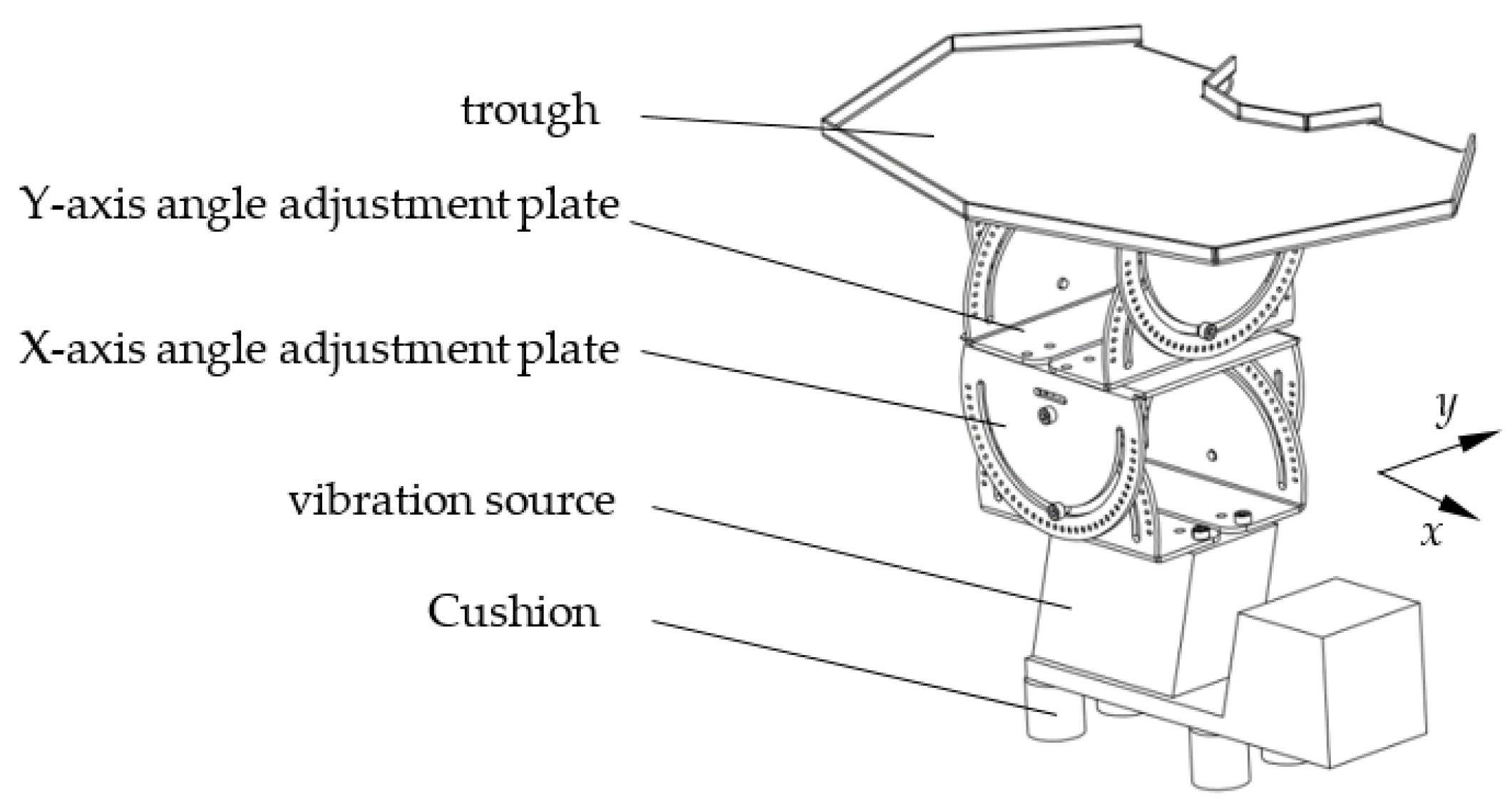
2.1.1. Structural Design of Orientation Device
2.1.2. Working Principle
2.2. Analysis of the Head and Tail Orientation Process of Fry
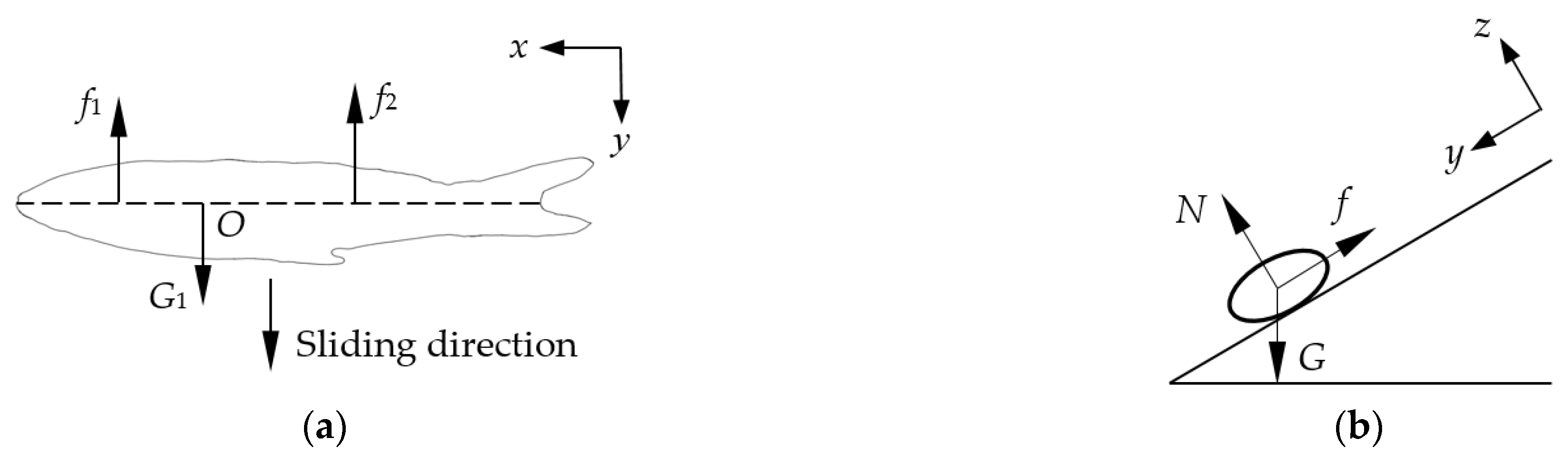
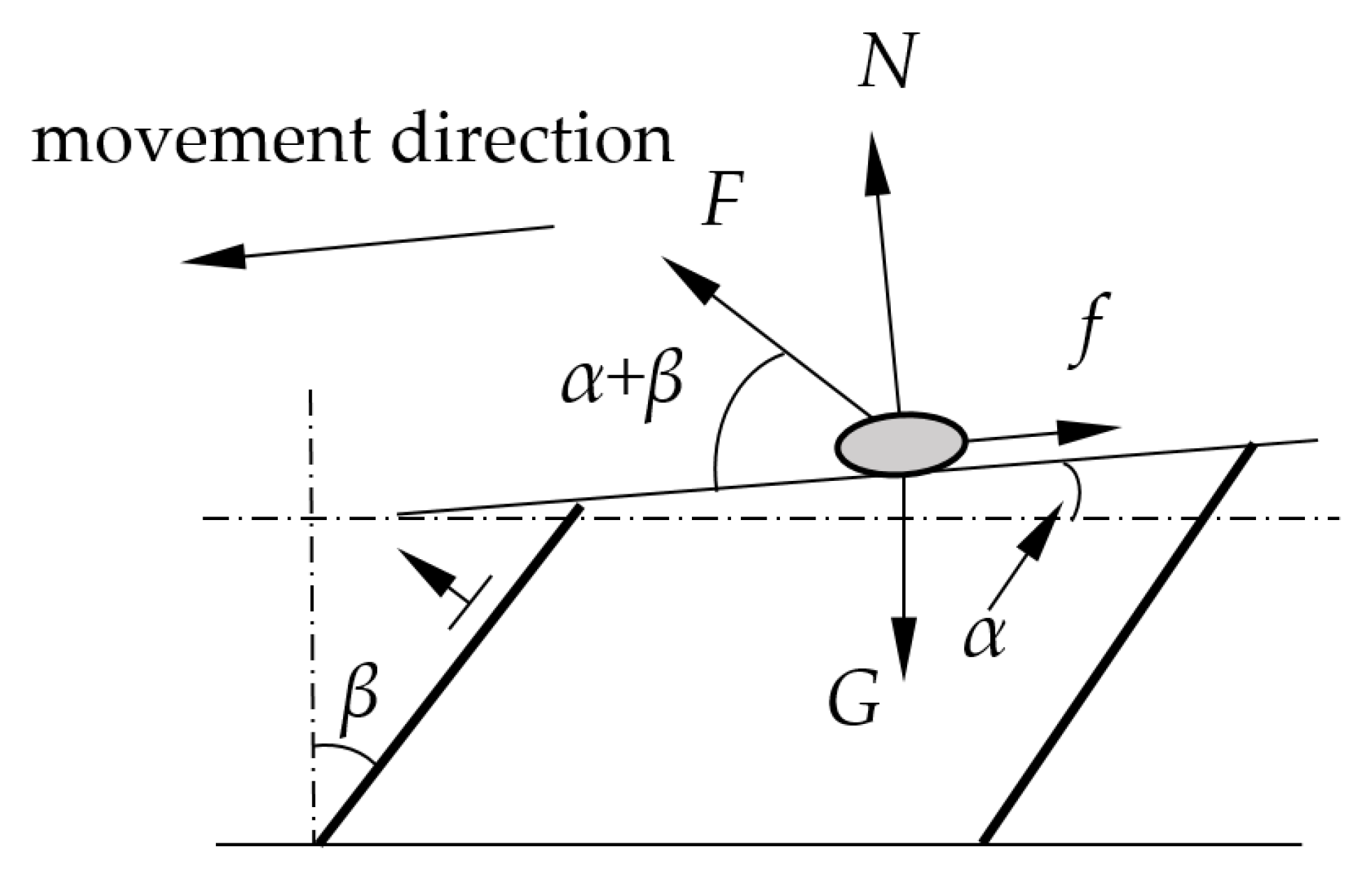
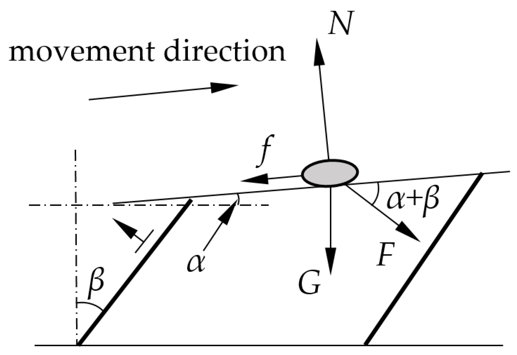
2.2.1. Fry Movement Status
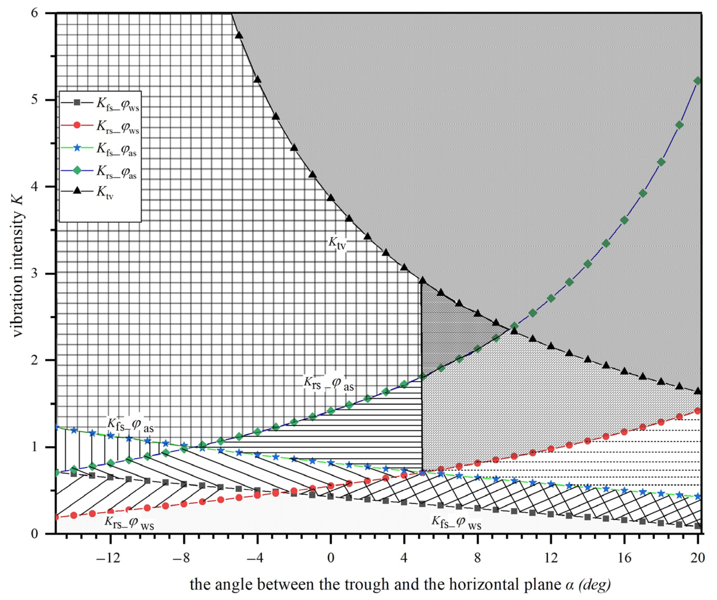
2.2.2. Fry Assemblage Movement Status
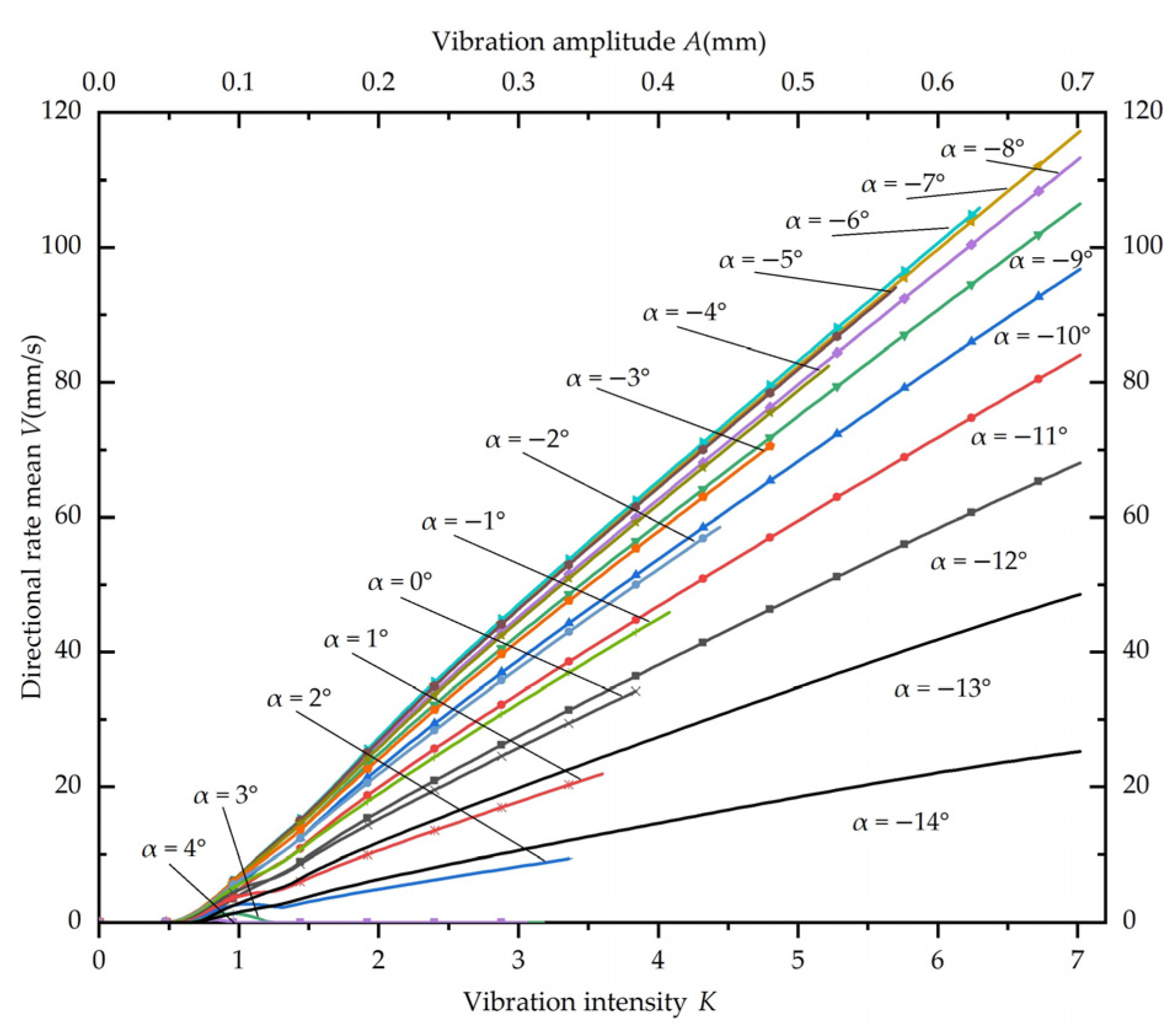
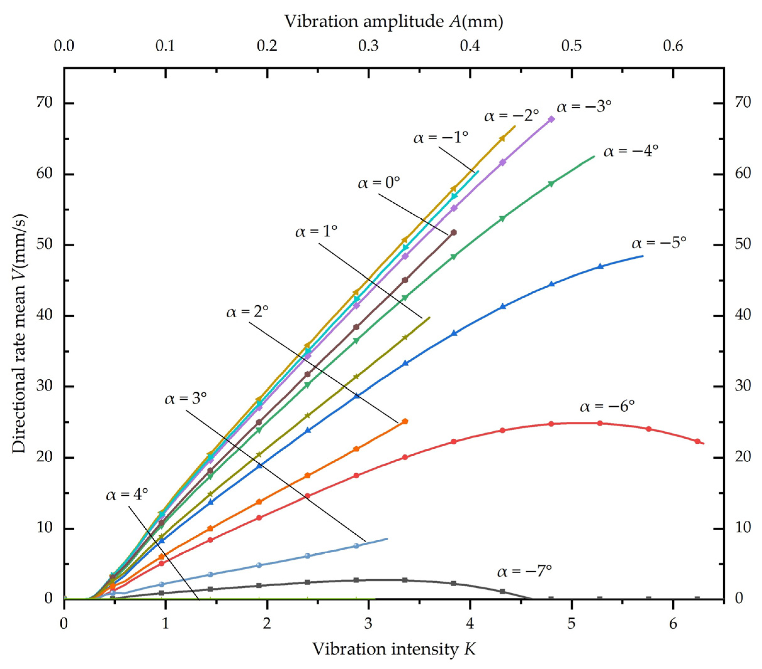
2.3. Simulation Calculation of Fry Speed Velocity
3. Results
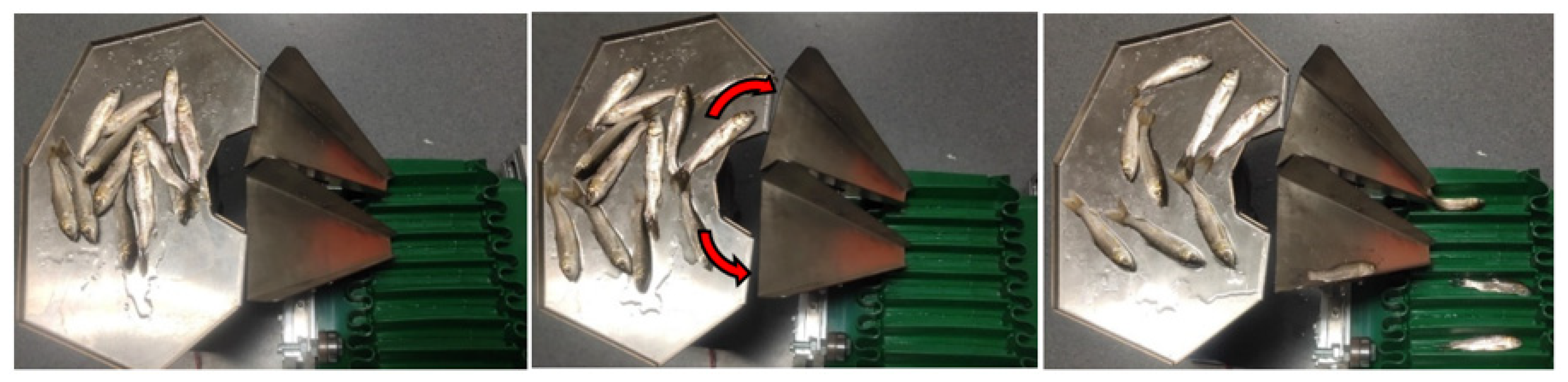
3.1. Test Process
3.2. Test Results and Analysis
4. Discussion
5. Conclusions
Author Contributions
Funding
Institutional Review Board Statement
Data Availability Statement
Acknowledgments
Conflicts of Interest
References
- Nakanishi, T. Preface—Development and use of vaccines for fish. Fish Shellfish. Immunol. 2020, 106, 218. [Google Scholar] [CrossRef] [PubMed]
- Wang, Q.C.; Jin, W.; Xu, Z. Current use and development of fish vaccines in China. Fish Shellfish. Immunol. 2020, 96, 223–234. [Google Scholar] [CrossRef] [PubMed]
- Wang, Q.Y. Fish vaccine technology development and application in China: A review. J. Dalian Ocean. Univ. 2022, 37, 1–9. [Google Scholar] [CrossRef]
- Li, D.D. Study on Automatic Injection Machine for Fish Based on Machine Vision. Master’s Thesis, Zhejiang University, Hangzhou, China, 2019. [Google Scholar]
- Zhang, J.W.; Chen, Q.Y.; Ou, Y.J.; Zhou, C.S. Research Progress on Pretreatment and Processing Technology of Freshwater Fish in China. Anhui Agric. Sci. 2018, 46, 25–28. [Google Scholar] [CrossRef]
- Xiang, Y.P.; Tan, H.Q.; Wan, P.; Huang, P.F.; Yang, C.X. Theoretical analysis and experimental study about head-tail orientation rule of silver carp on vibration platform. J. Huazhong Agric. Univ. 2017, 36, 130–138. [Google Scholar] [CrossRef]
- Gao, X.X.; Tan, H.Q. Design and experiment of directional transport device of freshwater fish bodies. Trans. CSAE 2011, 27, 342–347. [Google Scholar]
- Liu, W. Equipment Manufacture and Orientation Mechanism Study on Freshwater Fishes’ Heads and Backs. Master’s Thesis, Huazhong Agricultural University, Wuhan, China, 2013. [Google Scholar]
- Webster, J.; Bergman, P. Device and Method for Volitionally Orienting Fish: US5816196A. 1998. Available online: https://worldwide.espacenet.com/patent/search/family/024516040/publication/US5816196A?q=US5816196A (accessed on 3 January 2023).
- Zhang, M. Ordered Arrangement Device for Fish. CN105752659A. 2016. Available online: https://worldwide.espacenet.com/patent/search/family/056324217/publication/CN105752659A?q=CN105752659A&queryLang=en%3Ade%3Afr (accessed on 3 January 2023).
- Wan, P.; Guo, S.Q.; Yang, J.; Zhao, J.W.; Tan, H.Q.; Zhu, M. Horizontal reciprocating vibration method for head-to-tail directional transportation of fresh water fish. Trans. CSAE 2021, 37, 40–48. [Google Scholar] [CrossRef]
- Lin, Q.Y.; Mu, J.C. Initial exploration of fish orientation machinery. Fish. Mod. 1980, 4, 7–9. [Google Scholar]
- Xu, S.B.; Xu, X.Y. A feasibility study on the development of mechanism for the directional transport of fish bodies. J. Zhejiang Ocean. Univ. 1990, 9, 131–134. [Google Scholar]
- Pegoraro, G.; Wadell, L. Fish Feed Apparatus and Method. EP0548383B. 1994. Available online: https://worldwide.espacenet.com/patent/search/family/008207456/publication/EP0548383A1?q=EP0548383 (accessed on 3 January 2023).
- Wang, Q.H. Research on the Equipment for Orientation and Cutting Head of Freshwater Fish. Master’s Thesis, Wuhan Polytechnic University, Wuhan, China, 2020. [Google Scholar]
- Andresen, H.; Eriksson, J.; Hagglund, J.; Hammeren, J.; Kleven, H.; Oppheim, P.; Vaagland, F. Device for Singularization of Fish. EP2820946A. 2015. Available online: https://worldwide.espacenet.com/patent/search/family/044115125/publication/EP2820946A1?q=EP2820946 (accessed on 3 January 2023).
- Wenzel, W. Device for Sorting Fish. US4613031. 1986. Available online: https://worldwide.espacenet.com/patent/search/family/006209443/publication/US4613031A?q=US4613031&queryLang=en%3Ade%3Afr (accessed on 3 January 2023).
- Yang, L.; Chen, Z.Y.; Xiao, H.P. Calculation of volume at both ends of liquid bridge between two parallel plates. Coll. Phys. 2021, 12, 12–14+19. [Google Scholar] [CrossRef]
- Geng, A.J.; Li, X.Y.; Hou, J.L.; Zhang, Z.L.; Zhang, J.; Chong, J. Design and experiment of automatic directing garlic planter. Trans. CSAE 2018, 34, 17–25. [Google Scholar] [CrossRef]
- Li, Y.H.; Liu, Q.C.; Li, T.H.; Wu, Y.Q.; Niu, Z.R.; Hou, J.L. Design and experiments of garlic bulbil orientation adjustment device using Jetson Nano processor. Trans. CSAE 2021, 37, 35–42. [Google Scholar] [CrossRef]
- Yu, Y.X.; Zhao, Y.; Zhang, B.; Li, G. Seed metering device based on orienting ordered arrangement in embryo and parameter optimization. J. Jiangsu Univ. Nat. Sci. Ed. 2008, 3, 194–197. [Google Scholar]
- Han, B.; Meng, F.C.; Liang, L.N.; Ge, Y.X.; Xu, H.Y. Performance experiment of directional precision seeding device for japonica rice. Trans. CSAE 2015, 31, 8–15. [Google Scholar] [CrossRef]
- Wang, Y.B.; Zhao, X.G.; Xu, L.M.; Li, C.; Lu, X.; Li, S.J. Experiment and Directional Movement Technology of Corn Seed Based on Electromagnetic Vibration. Trans. Chin. Soc. Agric. Mach. 2015, 45, 79–88. [Google Scholar] [CrossRef]
- Xing, J.J.; Xu, L.M.; Yuan, Q.C.; Ma, S.; Yu, C.C.; Duan, Z.Z. Design and test of pushing device for dent corn seeds directional sowing. Trans. CSAE 2018, 34, 9–15. [Google Scholar] [CrossRef]
- Chen, J.Y. Research on Key Technologies and Mechanisms of Automatic Fish Vaccine Injection Equipment. Master’s Thesis, Zhejiang University, Hangzhou, China, 2020. [Google Scholar]
- Gu, P.C. Research on feeding speed of electromagnetic vibration feeder. J. Mech. Electr. Eng. 2012, 29, 790–794. [Google Scholar]
- Yu, W.; Wu, J.X.; Lin, H.Z.; Wen, G.L.; Cao, Y.C.; Hu, X.L.; Huang, Z.; Yang, Y.K.; Li, T.; Zhao, W. Anesthetic effect of eugenol on lateolabrax maculatus. Hebei Fish. 2020, 4, 4–7+11. [Google Scholar] [CrossRef]


| Materials | Scale | Reverse Scale | Difference |
|---|---|---|---|
| 316L | 12.9° | 22.5° | 9.6° |
| PU | 38.3° | 42.5° | 4.2° |
| Silicone | 25.2° | 45.1° | 19.9° |
| Level | Angle θy | Amplitude | Materials | Empty |
|---|---|---|---|---|
| 1 | −2° | 0.4 mm | 316L | - |
| 2 | −4° | 0.5 mm | Silicone | - |
| 3 | −6° | 0.6 mm | - | - |
| 4 | −8° | 0.7 mm | - | - |
| Standard Sequence | Running Sequence | Angle θy | Vibration Amplitude A | Feeder Plane | Empty | Orientation Speed η | Success Rate ε |
|---|---|---|---|---|---|---|---|
| 1 | 16 | 1 (−2°) | 1 (0.4 mm) | 1 (316L) | 1 | 0.30 | 0.744 |
| 2 | 12 | 1 | 2 (0.5 mm) | 1 | 1 | 0.42 | 0.756 |
| 3 | 15 | 1 | 3 (0.6 mm) | 2 (Silicone) | 2 | 0.61 | 0.800 |
| 4 | 14 | 1 | 4 (0.7 mm) | 2 | 2 | 0.79 | 0.856 |
| 5 | 7 | 2 (−4°) | 1 | 1 | 2 | 0.35 | 0.711 |
| 6 | 8 | 2 | 2 | 1 | 2 | 0.42 | 0.744 |
| 7 | 3 | 2 | 3 | 2 | 1 | 0.66 | 0.900 |
| 8 | 4 | 2 | 4 | 2 | 1 | 0.87 | 0.956 |
| 9 | 9 | 3 (−6°) | 1 | 2 | 1 | 0.37 | 0.756 |
| 10 | 1 | 3 | 2 | 2 | 1 | 0.48 | 0.778 |
| 11 | 13 | 3 | 3 | 1 | 2 | 0.39 | 0.722 |
| 12 | 5 | 3 | 4 | 1 | 2 | 0.42 | 0.744 |
| 13 | 2 | 4 (−8°) | 1 | 2 | 2 | 0.45 | 0.889 |
| 14 | 11 | 4 | 2 | 2 | 2 | 0.53 | 0.911 |
| 15 | 10 | 4 | 3 | 1 | 1 | 0.32 | 0.700 |
| 16 | 6 | 4 | 4 | 1 | 1 | 0.34 | 0.744 |
| Variance | Freedom | Sum of Squares | Mean Sum of Squares | F-Value | p-Value |
|---|---|---|---|---|---|
| Angle | 3 | 0.083 | 0.028 | 8.14 | 0.011 |
| Amplitude | 3 | 0.115 | 0.038 | 11.36 | 0.004 |
| Material | 1 | 0.202 | 0.203 | 59.94 | 0.000 |
| Empty | 1 | 0.003 | 0.003 | 0.74 | 0.418 |
Disclaimer/Publisher’s Note: The statements, opinions and data contained in all publications are solely those of the individual author(s) and contributor(s) and not of MDPI and/or the editor(s). MDPI and/or the editor(s) disclaim responsibility for any injury to people or property resulting from any ideas, methods, instructions or products referred to in the content. |
© 2023 by the authors. Licensee MDPI, Basel, Switzerland. This article is an open access article distributed under the terms and conditions of the Creative Commons Attribution (CC BY) license (https://creativecommons.org/licenses/by/4.0/).
Share and Cite
Li, J.; Li, C.; Li, C.; Luo, W.; Wu, K.; Zhu, S.; Ye, Z. Design and Study of a Spindle-Shaped Fry Head-to-Tail Orientation Device. Fishes 2023, 8, 143. https://doi.org/10.3390/fishes8030143
Li J, Li C, Li C, Luo W, Wu K, Zhu S, Ye Z. Design and Study of a Spindle-Shaped Fry Head-to-Tail Orientation Device. Fishes. 2023; 8(3):143. https://doi.org/10.3390/fishes8030143
Chicago/Turabian StyleLi, Jianping, Chen Li, Congcong Li, Wei Luo, Kang Wu, Songming Zhu, and Zhangying Ye. 2023. "Design and Study of a Spindle-Shaped Fry Head-to-Tail Orientation Device" Fishes 8, no. 3: 143. https://doi.org/10.3390/fishes8030143
APA StyleLi, J., Li, C., Li, C., Luo, W., Wu, K., Zhu, S., & Ye, Z. (2023). Design and Study of a Spindle-Shaped Fry Head-to-Tail Orientation Device. Fishes, 8(3), 143. https://doi.org/10.3390/fishes8030143