Article

Intrinsic Run-Time Row Hammer PUFs: Leveraging the Row Hammer Effect for Run-Time Cryptography and Improved Security

1
Security Engineering Group, Computer Science Department, Technical University of Darmstadt, Mornewegstraße 32, S4|14, Darmstadt, 64293 Hessen, Germany
2
Department of Electrical Engineering and Information Technology, Technical University of Darmstadt, S3|06, Merckstraße 25, Darmstadt, 64283 Hessen, Germany
3
Measurement and Sensor Technology, Department of Electrical Engineering and Information Technology, Technical University of Darmstadt, S3|06, Merckstraße 25, Darmstadt, 64283 Hessen, Germany
4
Computer Architecture and Security Laboratory, Department of Electrical Engineering, Yale University, 10 Hillhouse Avenue, New Haven, CT 06520, USA
*
Author to whom correspondence should be addressed.
This paper is an extended version of our paper published in Proceedings of 2017 IEEE International Symposium on Hardware Oriented Security and Trust (HOST), 1–5 May 2017.
Cryptography 2018, 2(3), 13; https://doi.org/10.3390/cryptography2030013
Submission received: 27 April 2018 / Revised: 22 June 2018 / Accepted: 25 June 2018 / Published: 30 June 2018

Abstract

:
Physical Unclonable Functions (PUFs) based on the retention times of the cells of a Dynamic Random Access Memory (DRAM) can be utilised for the implementation of cost-efficient and lightweight cryptographic protocols. However, as recent work has demonstrated, the times needed in order to generate their responses may prohibit their widespread usage. To address this issue, the Row Hammer PUF has been proposed by Schaller et al., which leverages the row hammer effect in DRAM modules to reduce the retention times of their cells and, therefore, significantly speed up the generation times for the responses of PUFs based on these retention times. In this work, we extend the work of Schaller et al. by presenting a run-time accessible implementation of this PUF and by further reducing the time required for the generation of its responses. Additionally, we also provide a more thorough investigation of the effects of temperature variations on the Row Hammer PUF and briefly discuss potential statistical relationships between the cells used to implement it. As our results prove, the Row Hammer PUF could potentially provide an adequate level of security for Commercial Off-The-Shelf (COTS) devices, if its dependency on temperature is mitigated, and, may therefore, be commercially adopted in the near future.

1. Introduction

In recent years, attacks that exploit the effects of row hammering in Dynamic Random Access Memories (DRAMs) have gained a lot of attention. However, as proven by the work of Schaller et al. [1], which was published in 2017, the row hammer effect can also be used to actually enhance the security of a system, rather than diminish it. This paper extends the work of Schaller et al., demonstrating that the row hammer effect can be utilised to provide run-time accessible cryptographic applications and improved security.
The row hammer effect was first examined in detail in 2014, in a publication by Kim et al. [2], in which the authors discuss the vulnerability of high-density, commodity DRAM modules to so-called disturbance errors caused by repeatedly accessing uncached memory rows. Disturbance errors occur due to the charge coupling between DRAM cells, which accelerates charge leakage in adjacent rows, and eventually results in bits being flipped in so-called victim rows in DRAM, even though the victim rows were not explicitly accessed.
The row hammer effect allows for breaking many software-based security mechanisms, as well as memory and process isolation, because it allows flipping memory bits, which would otherwise be protected by software-based access control mechanisms. While most relevant publications tend to focus on the realisation of attacks utilising the row hammer effect and countermeasures against them [3,4,5,6,7,8,9], Schaller et al. [1] presented, in 2017, a Physical Unclonable Function (PUF) based on the row hammer effect, proving, in this way, that the row hammer effect can also be utilised for security-enhancing applications.
The Row Hammer PUF, as Schaller et al. [1] call their novel PUF implementation is, in fact, leveraging the row hammer effect in DRAM modules to reduce the retention times of their cells and, thus, significantly speed up the generation times for the responses of PUFs based on these retention times. This PUF can, therefore, be considered as both an improved rendition of the DRAM retention-based PUF and as a novel PUF implementation, as it takes advantage of not only the retention characteristic of the DRAM cells, but also of the row hammer effect.
In this case, contrary to the other known applications of the row hammer effect, the fact that the vast majority of contemporary DRAMs seems to be vulnerable to row hammering, as noted in [2], is proven to be advantageous for the security of the computer systems incorporating them. In particular, a run-time accessible Row Hammer PUF can allow for a flexible and cost-efficient implementation of cryptographic applications, e.g., key agreement, identification and authentication protocols, even in low-end devices, such as the hardware usually employed in the Internet of Things (IoT).
DRAM-based PUFs are a relatively new category of memory-based PUFs, as the first relevant publications appeared in 2012 [10,11,12,13]. In particular, there are multiple categories of DRAM-based PUFs, each of which takes advantage of a different physical characteristic of the DRAM [14], such as the startup values of the DRAM cells [15,16], their retention times [17,18] and their access latency regarding both the relevant write and read operations [19,20]. In this paper, we focus rather on DRAM PUFs based on the retention times of the DRAM cells, in the presence of the row hammer effect in them. Traditional DRAM retention-based PUFs suffer from high generation times [20], while the Row Hammer PUF introduced by Schaller et al. [1] allows for relatively low generation times.
In this paper, we examine how these generation times can be lowered even further, present and evaluate a run-time accessible implementation of the Row Hammer PUF presented in the work of Schaller et al. [1], investigate in detail the effects of temperature on the different implementations of the Row Hammer PUF and provide a brief discussion regarding potential statistical relationships among the cells used to implement it. In this way, we aim to demonstrate that the Row Hammer PUF is a flexible, lightweight, cost-efficient and practical security primitive that can be used as a basis for the implementation of cryptographic applications, e.g., key agreement [17] and authentication [17,18] protocols that have been implemented using the exact same hardware, and, therefore, significantly strengthen the security of systems that contain DRAMs vulnerable to the row hammer effect.
Finally, the Row Hammer PUF not only does not require the addition of hardware for its construction and operation, similar to other intrinsic memory-based PUFs, such as SRAM PUFs, but, unlike most of those PUFs, which can only be accessed during boot-time and provide a single input–output pair, the Row Hammer PUF can also be accessed during run-time and provides multiple Challenge–Response pairs (CRPs), as the input–output pairs of a PUF are usually referred to. Thus, the Row Hammer PUF may be a DRAM-based PUF implementation that could potentially be commercially adopted, especially as a security primitive for the implementation of cryptographic applications in low-end devices, such as IoT hardware, that usually cannot support other more demanding security mechanisms, such as a Trusted Platform Module (TPM), due to their limited resources.

1.1. Contributions of This Paper

To present the contributions of this paper in a transparent manner, we first list the contributions made by the original work of Schaller et al. [1] that this paper extends, and then presents the additional contributions made by this paper.
The original paper by Schaller et al. [1], which this paper extends, made the following contribution in the field of PUFs:
  • It introduced the Row Hammer PUF, whose implementation is based on unique disturbance errors among DRAM rows, caused by the row hammer effect.
  • It discussed, in detail, the implementation of this PUF on Commercial Off-The-Shelf (COTS) devices, which does not require additional hardware for its construction or operation. It is also noted that this PUF could potentially be made accessible at run-time.
  • Additionally, it provided an extensive evaluation, presenting very good results regarding the uniqueness, robustness and entropy of its responses.
  • Finally, it also presented a limited study of the effects of temperature on the operation of this PUF.
This paper extends the work done by Schaller et al. [1] by making the following additional contributions:
  • We present and evaluate a flexible run-time accessible implementation of the Row Hammer PUF on COTS devices, based on the usage of a Linux kernel module.
  • We also improve, in some cases, the time required for the generation of responses from the Row Hammer PUF, by fully disabling the caching of row hammering operations, and therefore increasing the rate at which bits flip.
  • Furthermore, we present an extensive evaluation of the proposed implementations of the Row Hammer PUF, in order to provide an adequate comparison of their uniqueness, robustness and the entropy of their responses, both for the original implementation and for the implementations proposed in this work.
  • Additionally, we also provide an extended investigation of the way temperature affects the responses of the Row Hammer PUF.
  • Moreover, we examine whether potential statistical relationships exist among the cells used to implement it.
  • Finally, we briefly discuss the potential of the Row Hammer PUF for commercial adoption.

1.2. Outline of This Paper

The rest of this paper is organised in the following way. Section 2 provides background information regarding DRAMs and briefly presents the literature relevant to this paper, including both works regarding the row hammer effect and ones concerning memory-based intrinsic PUFs. The implementation setup of the original Row Hammer PUF and our improved implementations of this PUF are discussed in Section 3. Subsequently, these implementations are evaluated in Section 4, where also an extended investigation regarding the effects of temperature variations on the Row Hammer PUF is provided. Additionally, we briefly examine, in this section, whether there is any significant statistical relationship among the cells that are used to produce the Row Hammer PUF responses. Furthermore, we also briefly discuss the potential of the Row Hammer PUF to be commercially adopted, taking into account its dependency on temperature. Finally, Section 5 concludes the paper providing useful remarks and helpful insights that can be drawn from the evaluation of the different implementations of the Row Hammer PUF.

2. Background and Related Literature

In this section, we provide some background information on the way DRAMs work and briefly discuss works relevant to this paper. We examine briefly literature concerning either of the two main topics related to this paper, the row hammer effect and memory-based intrinsic PUFs.

2.1. DRAM Data Storage and Access

The most common contemporary design for a DRAM cell consists of one transistor and one capacitor, as shown in Figure 1. The transistor acts as a gatekeeper, regulating access to the capacitor, whose charged or discharged state indicates the logical value stored in the DRAM cell. The gate of the transistor is connected to a wordline (WL) that controls access to the whole row. The capacitor is connected to a bitline (BL) through the transistor. Each bitline is also connected to an equaliser and a sense amplifier that are used to convert the capacitor’s charge to a logical value. DRAM cells are quite often separated into true cells, whose charged state indicates logical one, and anti-cells, whose charged state represents logical zero [21]. For both types of cells, their discharged states indicate the opposite logical value from that of their charged states. In Figure 1, we represent true cells as being connected to a BL bitline and anti-cells as connected to a BL* bitline.
DRAM cells are organised in arrays, which are called banks, which are usually further organised in sets of matrices of DRAM cells, in the way Figure 1 demonstrates. When a memory address is accessed, the relevant bank is selected and the appropriate row and column in that bank are activated, through the corresponding global wordline (GWL) and global bitline (GBL), respectively. Subsequently, the relevant matrix in that bank is selected and the appropriate local row and column are activated, through the corresponding local wordline (WL) and local bitline (BL). The relevant global wordlines and bitlines of each bank are used in order to activate the local wordlines and bitlines of each matrix of DRAM cells found inside that bank. To this end, an elaborate system of logic for address decoding and row and column selection exists both at bank level and at matrix level, as well as a system of global equalisers and sense amplifiers inside each bank and of local equalisers and sense amplifiers inside each matrix, as Figure 1 shows. The need for such an intricate system of logic raises the demand for a large scale of integration.
The charge stored in the capacitor of a DRAM cell leaks over time, leading the cell’s logical value to flip. Therefore, the time required for enough charge to leak from a cell’s capacitor is equivalent to its data retention time. Charge can leak from a cell’s capacitor either to components of that cell itself or to components of other cells, which may be in the same or in different rows, as indicated in Figure 1 by the blue arrows. Therefore, in order to prevent data stored in the DRAM cells from leaking, the cells need to be accessed periodically, in order to reinforce their stored values, through a process being referred to as the refresh operation. To ensure data integrity, each DRAM row needs to be refreshed with a certain frequency, which is in the order of milliseconds for most contemporary DRAM implementations.
To access a particular cell, the corresponding bank is selected and, on that bank, the correct global wordline and global bitline are charged, in order to allow access to a particular row and column, respectively, of that bank. This operation leads to the activation of a whole row of DRAM matrices. Then, the appropriate matrix is selected and the correct local wordline and local bitline, on that matrix, are charged, in order to allow access to a particular row and column, respectively, of that matrix. This operation leads to the activation of a whole row of DRAM cells, as their transistors are activated through the same wordline, as Figure 1 indicates. Therefore, all operations in the DRAM, such as reading, writing and refreshing, tend to take place at the level of a whole row of a matrix or at the level of a whole row of a bank, which in this case is being referred to as a sub-array [22], depending on whether rows, found at the same row level, in the different matrices of the same sub-array are made to be accessed simultaneously or not [23,24].

2.2. The Row Hammer Effect in DRAM

In recent years, large scale integration and higher clock frequencies being used in DRAMs have brought into the spotlight the significance of the row hammer effect for the security of contemporary DRAM implementations [2,25,26]. Due to large scale integration, adjacent DRAM components, such as bitlines, wordlines, transistors and capacitors, start to exhibit coupling effects, which accelerate charge leakage in adjacent DRAM cells. Additionally, high clock frequencies, allow for more frequent access to different DRAM rows. When uncached DRAM rows are rapidly and repeatedly accessed, in an operation referred to as row hammering, their very frequent activation, in conjunction to the charge coupling between adjacent DRAM components, lead to a significant increase in the charge leakage of DRAM cells in rows adjacent to those being accessed, which can result in a quick change in the logical value of these cells, if they were initially in their charged state.
Therefore, the row hammer effect is an unintended side effect that occurs when a memory row, referred to as the hammer row, is rapidly and repeatedly accessed, causing cells in nearby rows, called victim rows, to leak charge more quickly [2,25,27,28,29]. This charge leakage can cause the cell’s logical value to change, causing what is known as a bit flip. Such bit flips are persistent to the refresh operation [29]. These disturbance errors are based on the induced increase in the crosstalk among adjacent DRAM components, such as bitlines, wordlines, transistors and capacitors, due to the frequent activation of the hammer rows, when these rows are not available through the use of the cache memory, but are accessed directly on the DRAM itself.
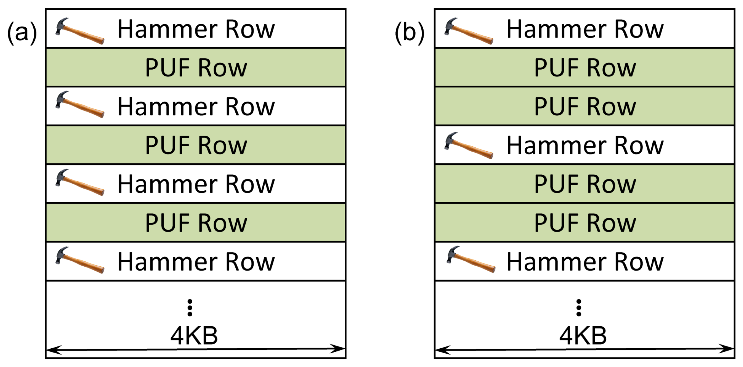
It has been shown that hammering a row will most likely affect its two adjacent rows. Consequently, we can distinguish between single-sided row hammering, where one hammer row is used to affect its two adjacent rows, and double-sided row hammering, where two (hammer) rows adjacent to the same victim row are hammered, in order to increase the chance of bit flips [3]. Of course, these two hammer rows may also affect their adjacent (victim) row that is not adjacent to both of them. The distinction between single-sided and double-sided row hammering is evident on Figure 2.
Usually, to allow for a sufficiently high DRAM access rate, and thus to trigger disturbance errors through the row hammer effect, non-cached memory accesses are needed, e.g., by leveraging the CLFLUSH instruction. Lately, several works have demonstrated the feasibility of exploiting the row hammer effect on platforms that do not provide such cache line flush instructions. In order to circumvent CPU caching mechanisms and ensure direct access to DRAM, Gruss et al. [7] and Aweke et al. [8] enforce cache eviction through elaborate memory access patterns. Qiao and Seaborn [9] make use of x86 non-temporal store instructions, which do not use the CPU cache and van der Veen et al. [4] utilize non-cacheable Direct Memory Access (DMA) queries to exploit the row hammer effect.
Other papers have presented techniques to gain understanding of the locations of flipping bits. Razavi et al. [6] presented a technique that allows for targeted bit flips at arbitrary physical memory locations by combining the row hammer effect with memory duplication. To conduct predictable row hammer attacks, van der Veen et al. [4] use a brute-force approach to hammer all DRAM rows and collect information about expectable bit flip locations. Finally, in the work of Jung et al. [30] a novel approach is presented that allows for reconstructing the physical layout of DRAM cells, by applying multiple temperature gradients on the memory module and observing DRAM data retention, which can allow for row hammer attacks of high precision.
Since its discovery, the row hammer effect has been used mainly as means of attacking a computer system. In particular, changing the contents of memory cells can result in modification of important data. Seaborn and Dullien [3] as well as van der Veen et al. [4] rely on the Row Hammer effect in order to gain root privileges, by flipping bits in page table entries. Xiao et al. [5] attack Xen’s paravirtualized memory isolation by employing the row hammer effect from within a malicious virtual machine. Razavi et al. [6] as well as Bhattacharya and Mukhopadhyay [31,32] successfully attack RSA by creating bit flips in keys stored in DRAM. Finally, Jang et al. [33] take advantage of the row hammer effect in order to successfully attack the memory isolation solution provided by the Intel Software Guard Extensions (SGX).
To the best of our knowledge, the work of Schaller et al. [1] is the only one that proposes the use of the row hammer effect in a DRAM in order to enhance the security of the relevant computer system that incorporates the DRAM, rather than diminish it. In this work, we extend and improve their techniques, in order to allow for improved security and run-time cryptographic applications. Additionally, we briefly explore the potential of the examined security scheme for commercial adoption.

2.3. Memory-Based Intrinsic PUFs

Physical Unclonable Functions (PUFs) ideally act as functions encoded in hardware, which produce a unique output, being referred to as a response, for a specific input, being called a challenge. However, in practice, PUFs tend to provide slightly noisy responses, which could affect their reliability [34,35]. For this reason, usually a fuzzy extractor scheme, which incorporates some Error Correction Code (ECC) [12], needs to be applied, in order to stabilise the PUF response [36].
The Row Hammer PUF, like most memory-based PUF implementations, is an intrinsic PUF and, therefore, its implementation does not require the addition of extra circuitry either for its construction or for its operation. Some other well-known memory-based intrinsic PUFs include the SRAM PUF [37,38], the Flash PUF [39] and different types of DRAM PUFs based either on the startup values of the DRAM cells [15,16] or on their retention times [10,11,12,17] or on the access latency times of the DRAM operations [19,20]. Intrinsic PUFs act as inherent security primitives and can, therefore, be used to enhance the security of low-end devices, such as IoT hardware, that usually cannot support other more demanding security mechanisms, such as a Trusted Platform Module (TPM), due to their limited resources.
Depending on the number of their available input–output pairs, which are referred to as Challenge–Response Pairs (CRPs), PUFs can provide a varying level of security and can, therefore, be used in different applications. The most common applications of PUFs include secure key storage and key agreement, as well as identification and authentication. A distinction can be made between PUFs with a single or very few CRPs, which are referred to as “weak” PUFs, and PUFs with a large number of CRPs, such that their complete characterisation within a limited timeframe is not possible, which are called “strong” [40,41].
Although memory-based PUFs are usually considered as “weak” PUFs, in this work, we refrain from judging whether the Row Hammer PUF is a “weak” or a “strong” PUF implementation, and only note that it can provide multiple CRPs. This property of the Row Hammer PUF could be considered as a potential advantage over other memory-based PUFs that can provide only a single CRP, such as PUF implementations based on the startup values of SRAMs and DRAMs. Additionally, while the SRAM PUF can only be accessed at boot-time, the Row Hammer PUF, as this work proves, can also be accessed at run-time, therefore allowing for the implementation of PUF-based cryptographic applications at run-time.
However, while SRAM PUFs have been studied extensively [42,43], DRAM-based PUFs, such as the Row Hammer PUF, have not yet been fully studied. Therefore, and as this work also proves, while DRAM-based PUFs, such as the Row Hammer PUF may have a number of advantages over other memory-based PUFs, such as SRAM PUFs, they also still suffer from a number of shortcomings, such as their dependency on temperature. These open issues will need to be addressed in order to explore the full potential of DRAM-based PUFs, including the Row Hammer PUF, for commercial adoption [14]. Nevertheless, some of the identified shortcomings of some DRAM-based PUFs are being addressed in recent literature, e.g., as this works demonstrates, the Row Hammer PUF implementation can reduce significantly the time required for the generation of responses, in comparison to the ordinary DRAM retention-based PUF implementations.
Finally, as the Row Hammer PUF is implemented in DRAM, which is an essential memory component of most contemporary computer systems, it allows for the efficient implementation of run-time cryptographic applications even on resource-constrained devices, such as IoT hardware, which may not support the use of other, more complex and resource-demanding security primitives.

3. Run-Time Row Hammer PUF Implementations in Commodity DRAM

In this section, we examine in detail the different parameters and factors that can affect the operation of a Row Hammer PUF. Additionally, we present and discuss our Row Hammer PUF implementations, in comparison to the implementation presented by Schaller et al. [1]. In particular, we introduce a more flexible firmware implementation and a run-time accessible kernel module implementation of the Row Hammer PUF. The latter leverages a Linux kernel module, in a similar way to the work of Xiong et al. [17], in order to provide access to the DRAM characteristics utilised by the Row Hammer PUF.
As noted in previous works, the locations of the disturbance errors caused by the row hammer effect in DRAM cells are stable [2,4]. This makes the row hammer effect a promising candidate for a PUF. However, the number of bit flips introduced by the Row Hammer effect can be relatively small, and thus may only provide a limited amount of entropy. For this reason, the Row Hammer PUF takes advantage not only of the effect that the row hammer has on the DRAM cells, but also of their data retention characteristic. In this way, it manages to significantly decrease the time required for the generation of responses and, therefore, address a known problem of the DRAM retention-based PUF, which has been noted in the recent literature [20]. Finally, further increases in the entropy of the responses of the Row Hammer PUF can be achieved by increasing the number of DRAM rows used in order to implement this PUF, as well as by controlling the initial values of the DRAM cells in both the hammer and the victim rows.

3.1. Row Hammer PUF Parameters

Our implementation setup is based on the inherent DRAM of a PandaBoard ES, the same DRAM that was employed also in the work of Schaller et al. [1] that introduces the original Row Hammer PUF, in order to facilitate comparisons between our results and the results of that work. Our PandaBoard ES implementations demonstrate that the Row Hammer PUF can be implemented on older low-end devices, which are currently already deployed and should be relatively cheap to acquire. Therefore, we believe that the implementations and results presented in this work would also be applicable on the majority of the devices that incorporate DRAM modules that are susceptible to the row hammer effect.
In general, the operation of the Row Hammer PUF is influenced by a number of different parameters, which can be exploited in order to increase the number of potential responses of this PUF. The most influential of these parameters are examined in this section, while other additional factors that can affect the operation and performance of the Row Hammer PUF are discussed in Section 3.3.
In particular, we note the following significant parameters that have been examined in order to test their influence on the responses of the Row Hammer PUF:
  • Row hammering type: There are two approaches to induce the row hammer effect described in the relevant literature [3,8]. Therefore, we can distinguish between two different Row Hammering types (RH types). If for one victim row there is only one adjacent hammer row, used to induce bit flips, we call it Single-Sided Row Hammering (SSRH). In contrast, Double-Sided Row Hammering (DSRH) involves the usage of both neighbours of a particular victim row as hammer rows. The patterns of hammer and victim rows, used to conduct SSRH and DSRH are shown in Figure 2. As we utilise the bit flips of a number of victim rows as the PUF response, we refer to these rows as PUF rows, as indicated in Figure 2.
  • PUF address and size: The PUF address defines the starting address of a PUF in the DRAM. The PUF size depends on the number of victim rows that are employed for the implementation of the Row Hammer PUF (PUF rows in Figure 2). Due to the existence of hammer rows, PUF rows are not consecutive. The PUF size and the RH type influence the actual hammering frequency, as a smaller PUF size will allow each hammer row to be accessed more frequently. Likewise, SSRH has fewer hammer rows, so each can be accessed more often within the same time period.
  • Initial Value (IV) of the hammer rows: For the memory range that corresponds to PUF address and PUF size, corresponding hammer rows will be pre-initialized by writing the hammer row IV to them, before conducting the row hammer process.
  • Initial Value (IV) of the PUF rows: Similarly, all PUF rows that are included in this memory range are initialized with the PUF row IV before the Row Hammer process is started. Both, the hammer row IV and the PUF row IV are important parameters because disturbance errors are caused by the interaction of the charges of DRAM cells, which are dependent on the logical values of these cells. Furthermore, as already mentioned, DRAM cells may be divided into so-called true cells and anti-cells, which represent the same logical value using different charge states [21]. True cells have a logical value of one when charged and a logical value of zero when discharged, while anti-cells have the opposite values for these charge states. Consequently, initializing a true cell with a value of logical zero or an anti-cell with logical one will most likely prevent bit flips from occurring in these cells. Thus, it is important to evaluate the effect of different values of PUF row IV and hammer row IV. As the layout of true and anti-cells is identical for DRAM modules of the same type, once optimal settings for both sets of initial values have been found, they can be used for all other instances of the same device type.
  • Row hammering time: The Row Hammering time (RH time) defines the total duration of the PUF measurement, including the time needed to disable the refresh operation and conduct the row hammering process. The RH time, just as the PUF size and the RH type, affects how many times each hammer row will be accessed in total.

3.2. Row Hammer PUF Queries

Taking into account the above-mentioned parameters, the process of querying a Row Hammer PUF is depicted in Algorithm 1. First, based on the PUF address, the PUF size and the RH type, the DRAM region that will be used for the Row Hammer PUF is reserved, so that no other program can access it. Next, the PUF rows and hammer rows are initialized with PUF row IV and hammer row IV, respectively. Then, memory caching is disabled, if it has been enabled, for the hammer rows, in order to ensure that all the row hammering commands executed will result in accesses in the DRAM itself. The PUF query is started by disabling the DRAM auto-refresh for the PUF rows in the next step. This is done using the same technique as the one employed by Xiong et al. [17]. Subsequently, the row hammering process is started. For this purpose, the hammer rows need to be accessed and activated repeatedly for a certain time. This is achieved by a read operation to the first word of each hammer row, which in turn causes the whole DRAM row to be refreshed. Hence, bits in the PUF rows may start to leak charge and eventually flip. After RH time has passed, the row hammering process ends and the DRAM auto-refresh is enabled again, for the PUF rows. If memory caching for the hammer rows was enabled before the execution of Figure 1, then it is enabled again. Finally, the PUF response is read from the PUF rows.
Algorithm 1: Process of querying a Row Hammer PUF. (Algorithm adapted from the original paper by Schaller et al. [1].)
Cryptography 02 00013 i001

3.3. Additional Factors That Can Affect the Row Hammer PUF

As the Row Hammer PUF is inherently tied to the underlying physical properties of the DRAM modules, there is a number of additional factors that can influence its operation. In particular, external factors, such as the temperature and the voltage supply, as well as internal components, such as error correction implementations, can affect the properties and operation of the DRAM in general, and thus also significantly affect the responses of the Row Hammer PUF.
We discuss these factors and their potential influence on the Row Hammer PUF responses in more detail, as follows:
  • Temperature: Prior work has shown that victim cells are not strongly affected by temperature [2]. However, the Row Hammer PUF is based on the interaction between the row hammer effect and the DRAM decay, which was shown to be temperature-dependent [17,20]. We, therefore, evaluate the temperature effect in Section 4, which confirms that the Row Hammer PUF is significantly affected by temperature, exhibiting increased bit flips at higher temperatures. While, for low temperature variations, the noise levels are stable and low, for high temperature variations, the increase in the number of bit flips is such that it significantly differentiates the PUF responses.
  • Voltage: Prior work has shown that the voltage supply affects the leakage of DRAM cells [44]. In COTS devices there is currently no interface to control the voltage of DRAM cells. We assume that, for the Row Hammer PUF, the DRAM operates at the factory-specified voltage settings. The influence of voltage on the Row Hammer PUF will be investigated in future works. We do note, however, that changing the voltage supply of DRAM on commodity hardware, without affecting the supply of other components, such as its MicroController Unit (MCU), is not trivial, even when it is possible, as noted by Schaller et al. [18].
  • Error Correction Code (ECC): ECC can be used in DRAMs to protect from bit flips. Many DRAM modules, such as the DRAM of the PandaBoard ES platforms used in this work, do not have ECC implemented. Even if ECC is present, Aichinger [45] showed that ECC is not enough to mitigate the Row Hammer effect. To use the Row Hammer PUF in the presence of ECC, the PUF size would potentially have to be increased, in order to achieve a similar amount of bit flips. Nevertheless, if ECC is implemented, it could potentially be disabled while the Row Hammer PUF is being queried, either fully or only for the DRAM rows being used as PUF rows. Even if ECC is present and cannot be disabled, it could potentially also be used for inherent error correction of the PUF response, therefore improving the Row Hammer PUF operation, rather than hindering it. Finally, as relevant ECC registers would indicate the rows on which bit flips are being observed, this information could potentially also be exploited to enhance the PUF measurements. However, in this work, we assume that no ECC is used, and the exact influence of ECC on the Row Hammer PUF remains to be explored by future works. In general, the influence of ECC on the Row Hammer PUF is highly dependent on the characteristics of the ECC that is implemented and on whether its implementation allows for it to be disabled.

3.4. Implementation Setup

In this work, we test different implementations of the Row Hammer PUF that are based on the DRAM modules of multiple PandaBoard ES Rev. B3 evaluation board, which is the same implementation setup as the one used in the work of Schaller et al. [1] that introduced the Row Hammer PUF. In this way, we can facilitate comparisons between our results and the results of that work. All our PUF implementations are purely in software, leaving the hardware configuration unchanged.
The PandaBoard ES Revision B3 evaluation board incorporates a Texas Instruments OMAP 4460 System-on-Chip (SoC) module, which contains an ELPIDA B8164 B3PF-8D-F 1GB (2×4 Gb) Low Power Double Data Rate type 2 (LPDDR2) Synchronous Dynamic Random Access Memory (SDRAM) memory module in a Package-on-Package (PoP) configuration [46,47,48,49]. This DRAM module is divided into 2 chips, with each chip containing 2 dies [49]. The memory is also further divided in 8 banks and their overall row size is 32KB [49], with each bank, therefore, having a row size of 4KB.
The PUF responses produced by the boards can be transferred from them to a computer using a serial connection, in order to be stored for further analysis and processing, or can be printed out using the available inherent system commands. In both cases, either the full PUF response can be extracted or only the memory regions that contain bit flips and their values. Finally, the correct time points at which the row hammering should start and end are also calculated by our code, in such a way as not to stall the PandaBoard’s microprocessor.
We need to also note that the PandaBoard’s DRAM module has been fabricated using a 90 nm manufacturing process. Therefore, further research may be required in order to evaluate the performance of different row hammer implementations on DRAM modules that have been fabricated based on more novel manufacturing processes or designs.

3.5. Firmware Implementation

The original Row Hammer PUF implementation described by Schaller et al. [1] was realised using the U-Boot boot-loader [50]. We have also tested this implementation, for the purposes of this paper, in order to compare it with the other implementations we present in this work. In the original implementation, the Row Hammer PUF is queried during an early stage during DRAM initialisation, before caching is enabled by the boot-loader. In this way, caching of the row hammering commands could be avoided, in order to ensure that the hammer rows in the DRAM are accessed every time using these commands.
In this work, we also present and test a similar firmware implementation, in which caching is completely disabled by setting the relevant registers that control the cache to appropriate values through software. This change should make our implementation more flexible, as it can be invoked even after the caching has been enabled by the boot-loader. This firmware implementation can be set to perform both SSRH and DSRH, enable or disable memory caching, use different sets of initial values as hammer row IV and PUF row IV and, finally, work for different RH time, PUF address and PUF size. Using these parameters, the Row Hammer PUF is queried as shown in Figure 1.
Since the DRAM is idle while the U-Boot boot-loader is running, queries to the Row Hammer PUF can be conducted without affecting any other functions of the platform. In U-Boot, one can also control the DRAM refresh cycle, as demonstrated by Xiong et al. [17]. Furthermore, although the PandaBoard implements an ARM processor that does not provide the CLFLUSH instruction, one can access physical DRAM addresses without caching, as described above.
The address organisation of the DRAM being examined can be deduced from the relevant manuals [46,47,48,49] and adequate testing. Since the internal die architecture of the DRAM is not known and address scrambling may be employed, as well as row redundancy, adequate testing, employing the techniques discussed in [30], may be required in order to achieve effective row hammering. After we disable interleaving, we allocate hammer rows and PUF rows in the same bank and make them adjacent, as shown in Figure 2. The firmware can access physical memory addresses and therefore allows direct access to physical memory locations, as long as these are not cached. To perform the row hammer operation, the hammer rows need to be activated repeatedly for a certain time. In our implementation this is achieved by a read operation to the first word of each hammer row.

3.6. Kernel Module Implementation

As noted in the work of Schaller et al. [1], the Row Hammer PUF can also be implemented using a kernel module, in order to achieve run-time access. Similar to the U-Boot functionality, the DRAM refresh operation can also be disabled from kernel space, as demonstrated by Xiong et al. [17]. As the PandaBoard has two different DRAM chips, the kernel and processes running can be constrained on one of these chips, which will keep being refreshed, while the other chip will be used for the implementation of the Row Hammer PUF, which involves disabling the refresh operation for some time, and manually refreshing critical data stored on the DRAM. Nevertheless, as Xiong et al. [17] have demonstrated, this method is applicable also to devices that have only a single DRAM chip. Even if the size of the DRAM makes it impossible to correctly refresh all the data stored in it, selective refresh techniques could potentially be employed in order to adequately refresh critical data.
Moreover, also for the kernel module implementation, caching is disabled in a flexible manner, by setting the relevant registers that control the cache to appropriate values through software. For the purposes of this work, we have implemented and tested such a run-time accessible Row Hammer PUF, using a Linux kernel module. This kernel module can be set to perform both SSRH and DSRH, enable or disable memory caching, use different sets of initial values as hammer row IV and PUF row IV and, finally, work for different RH time, PUF address and PUF size. Using these parameters, the module queries the Row Hammer PUF following the steps of Figure 1.
The module can be injected into the Linux kernel and run as one of the processes of the Linux Operating System (OS), without affecting its normal performance. The kernel module runs parallel to the other processes and is listed in the process list. Again, in this case, we disable interleaving and allocate hammer rows and PUF rows in the same bank and make them adjacent, as shown in Figure 2. The kernel module can only access virtual addresses, which have to be translated into physical ones by the system. Nevertheless, we can translate specific physical addresses into virtual ones and then use these virtual addresses within this module, in such a way as to access adjacent rows on the DRAM. Again, the address organisation of the DRAM being examined can be deduced from the relevant manuals [46,47,48,49] and adequate testing. Again, we need to note that as the internal die architecture of the DRAM is not known and address scrambling may be employed, as well as row redundancy, adequate testing, employing the techniques discussed in [30], may be required in order to achieve effective row hammering. Finally, to perform the row hammer operation, the hammer rows need to be activated repeatedly for a certain time. In our implementation this is achieved by a read operation to the first word of each hammer row.

3.7. Disabling the Cache Operation

The produced code runs in the PandaBoard’s Cortex A9 MicroProcessor Unit (MPU), which has a Cache Management Unit (CMU) that manages the caches of the MPU [48]. The CMU needs to be programmed in such a way as to force all the cache lines to remain invalidated while the row hammering process is running. This can be achieved by using the 64 range operation sets of the CMU [48]. Each range operation set has three registers that can be programmed to allow for a range operation to be performed over a memory region [48]. The first of these registers stores the starting physical address of the memory region, the second its length, which can range from 1 B to 4KB, and the third the type of operation to be performed, which can be clean, clean/invalidate or invalidate [48]. In this way, all levels of cache can be invalidated. Out of the 64 available range sets, only 56 can be allocated [48]. As the allocated registers need to be deallocated after their use, the allocations and deallocations of the range sets are done as an explicit step in the relevant Row Hammer PUF code, in which caching of the hammer rows being used in the Row Hammer PUF is being disabled. This ensures that the hammer rows in the DRAM are not cached when being accessed and, therefore, are accessed in the DRAM itself.

4. Evaluation

In this section, we evaluate the different implementations of the Row Hammer PUF according to their characteristics. We first present the original Row Hammer PUF implementation, introduced by Schaller et al. [1], and briefly discuss its relevant characteristics and evaluation. Then, we examine the different performance metrics by which the Row Hammer PUF implementations can be assessed, in general, as well as compared against each other. Additionally, we demonstrate and compare our results regarding the different Row Hammer PUF implementations, based on their characteristics. Furthermore, we investigate in detail how temperature affects the Row Hammer PUF and whether there are potential statistical relations among the PUF cells and their values. Moreover, we also present a way to increase the number of bit flips observed in the Row Hammer PUF response, by employing multiple instances of the Row Hammer PUF kernel module. Finally, we also examine the potential of the Row Hammer PUF for commercial adoption.

4.1. Evaluation of the Original Row Hammer PUF

The original Row Hammer PUF, which was introduced by Schaller et al. [1], in 2017, is based on a firmware implementation that was querying the PUF during an early stage during DRAM initialisation, before caching had been enabled by the boot-loader. This implementation was tested using the values of the Row Hammer PUF parameters shown in Table 1. It was examined how these parameters affected the number of observed bit flips and, then, this implementation was evaluated, using a fixed parameter configuration, with regards to its uniqueness, robustness and entropy. Additionally, it was briefly discussed how temperature variations could influence the Row Hammer PUF.
Furthermore, due to the lack of information about the distribution of true and anti-cells it was necessary to explore the correlation between such parameters as the hammer row IV and the PUF row IV of the Row Hammer PUF and its PUF behaviour experimentally, by testing various parameter settings. The reason for this was that most vendors of COTS, including the manufacturers of the PandaBoard, treat such implementation details regarding their hardware components as the distribution of true and anti-cells in the DRAM, as intellectual property and thus will not disclose them. However, one potential approach to retrieve the layout of true cells (and anti-cells) would be to initialize the DRAM with ‘0xFF’ (or ‘0x00’), disable the DRAM refresh operation and read back the memory contents after a period of several hours or days, i.e., at the end of the decay process. Such an approach has indeed been successfully tested by Kraft et al. [51].
In the original evaluation, three different memory regions, each located on one individual PandaBoard, had been measured, with each such memory region considered as a PUF instance. Therefore, three different PandaBoards had been employed for the evaluation of the Row Hammer PUF. For all of the measurements, the PUF address was fixed. For each parameter combination, 20 measurements were taken.
As Table 1 reveals, the original paper by Schaller et al. [1] considered a number of different values for the Row Hammer PUF parameters, focusing, however, on evaluating configuration settings that were expected to yield a good PUF. To extract the maximum possible entropy from the PUF, Schaller et al. primarily strived to maximize the number of bit flips. For this purpose, they needed to identify which parameters had the largest influence on the amount of bit flips. Their results, shown in Table 2 and Figure 3, reveal that the hammer row IV and the PUF row IV play a significant role in the amount of bit flips produced.
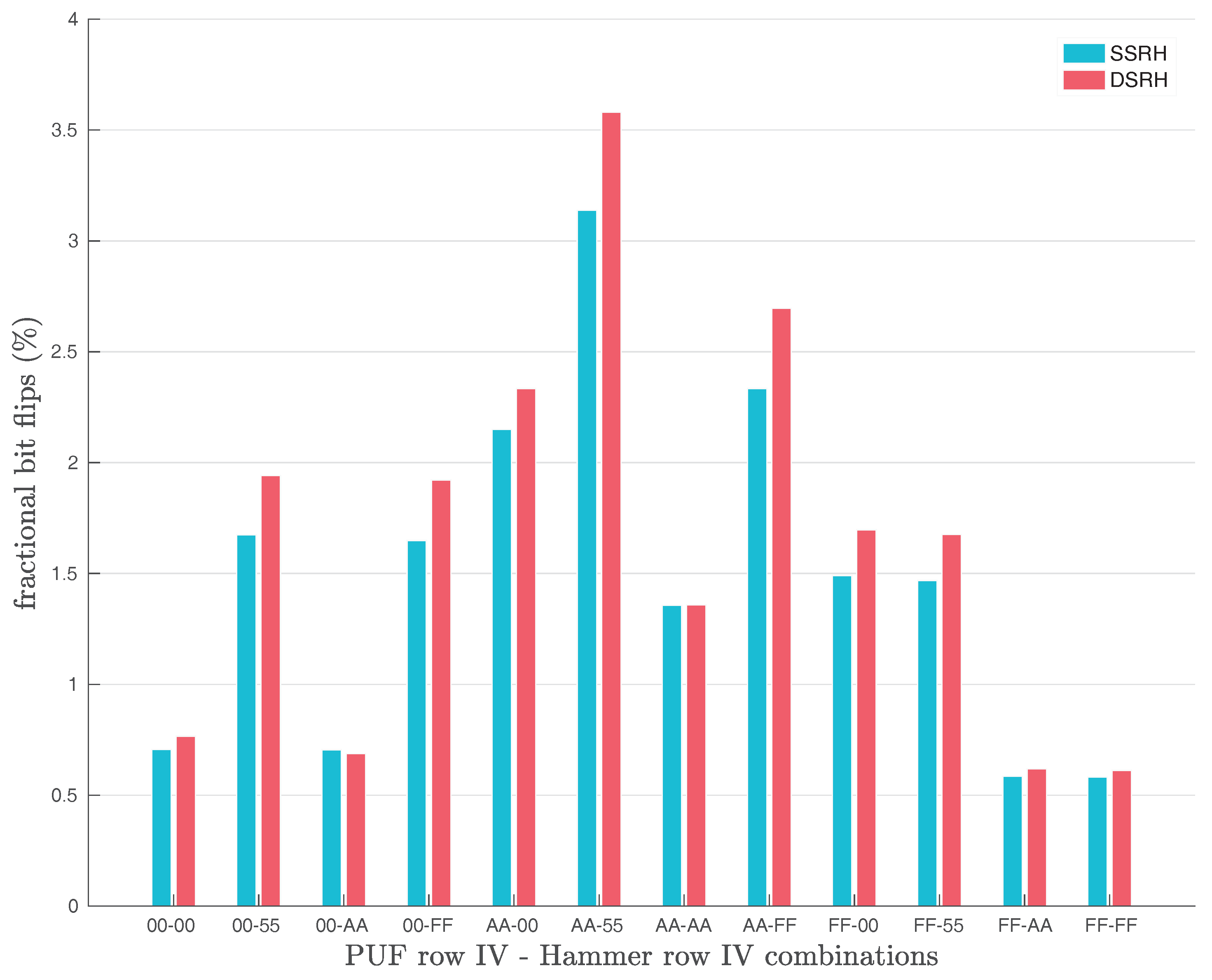
Furthermore, Schaller et al. [1] examined also the effects of Single-Sided (SSRH) and Double-Sided Row Hammering (DSRH) on the number of bit flips observed in the original Row Hammer PUF responses, as shown in Figure 4. Their results show that the use of DSRH results in slightly more bit flips observed than the use of SSRH. However, the difference in the number of bit flips produced with the two methods does not appear to be significant, as Figure 4 clearly indicates.
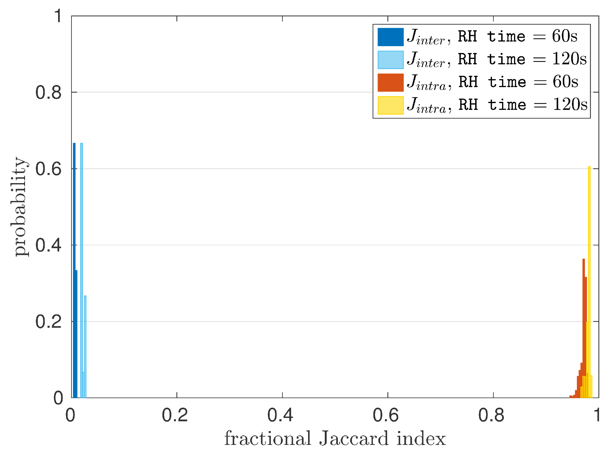
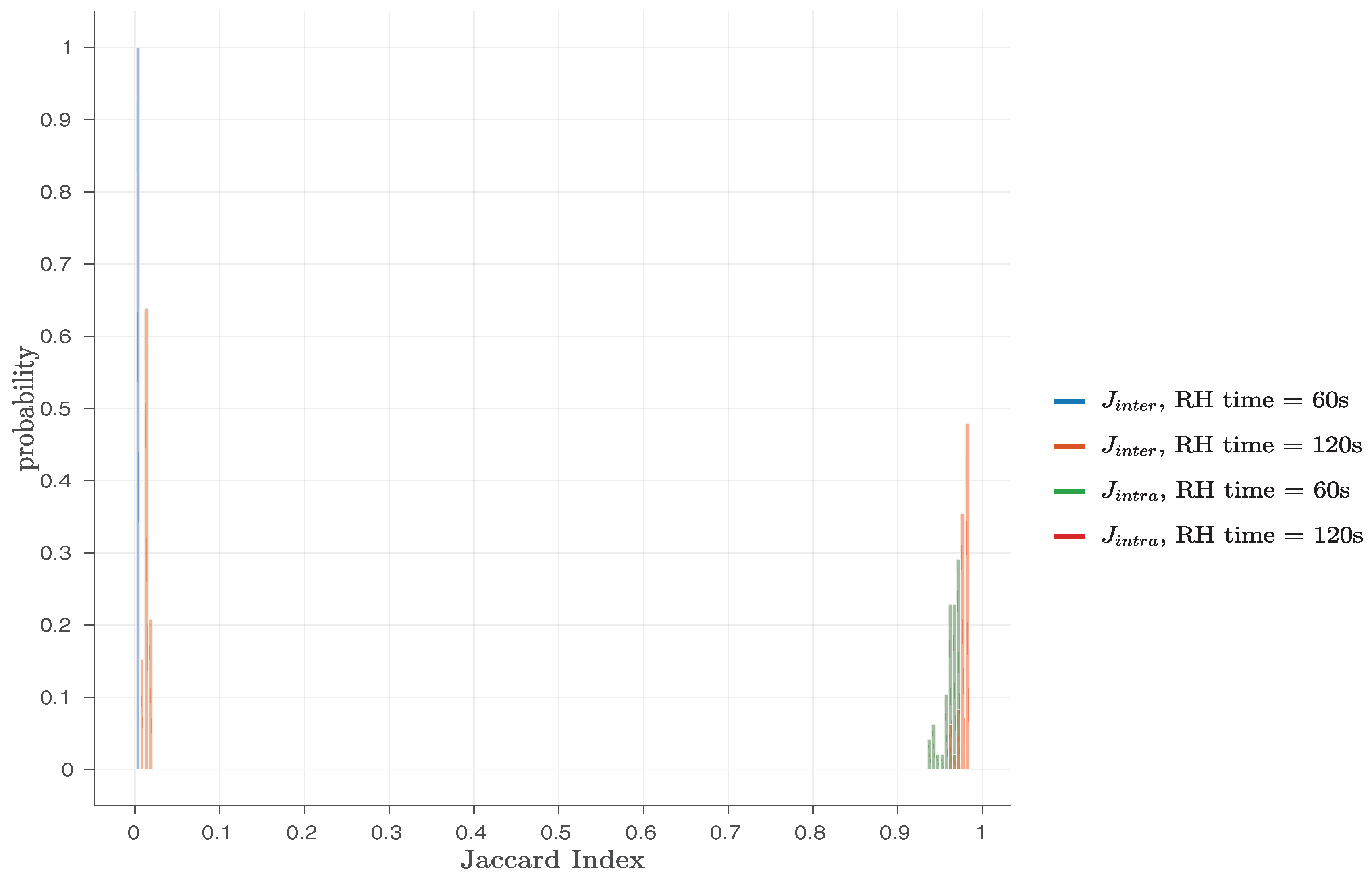
Finally, the original work by Schaller et al. [1] also considered the Jaccard index [52] for bit flips found in different responses of the same PandaBoard (intra-device Jaccard index— J i n t r a ) or of different PandaBoards (inter-device Jaccard index— J i n t e r ). By applying these metrics, they were able to prove that the original Row Hammer PUF responses exhibit a high degree of robustness and uniqueness, as the J i n t r a values were close to one and the J i n t e r values close to zero. As Table 2 and Figure 3 indicate, the original Row Hammer PUF provides the most bit flips and the highest entropy when hammer row IV = ‘0xAA’ and PUF row IV = ‘0x55’. For this reason, Schaller et al. [1] chose to present results for the J i n t r a and the J i n t e r values only for this case, which can be seen in Figure 5.
In Figure 5, histograms for both J i n t r a and J i n t e r are presented, for RH time set either to 60 s or 120 s and PUF row IV = ‘0xAA’, hammer row IV = ‘0x55’, PUF size = 128 KB and RH type = SSRH. This Figure shows that the values of J i n t r a and J i n t e r are not overlapping in any case, indicating that all the original Row Hammer PUF instances can be robustly and uniquely identified. With a minimum J i n t r a value of 0.9454 , the Row Hammer PUF measurements presented, exhibit a maximum noise of ≈5%, which can be easily corrected by standard Fuzzy Extractor (FE) constructions [53].
As DRAM retention-based PUFs exhibit high generation times for their responses, providing a relatively low amount of new bit flips over time, they usually exhibit a bias towards their original (non-flipped) values, which may even be public. Therefore, using metrics based on the Hamming distance, such as the intra-device and the inter-device Hamming distances, for their characterisation cannot usually provide useful insights into their performance. However, recent works [1,17,18,20,54] have shown that the use of similarly constructed metrics based on the Jaccard index of the positions of their flipped bits, such as the intra-device and inter-device Jaccard index, can provide a clear overview of their performance.
The J i n t r a and J i n t e r metrics are based on the Jaccard index [52], and for two sets s 1 and s 2 of position indices of flipped bits in two PUF responses R 1 and R 2 , respectively, the Jaccard index between these two responses is given by the formula:
J ( s 1 , s 2 ) = s 1 s 2 s 1 s 2 ,
which provides the similarity of the two sets, s 1 and s 2 . If R 1 and R 2 are obtained from the same PUF instance, then J( s 1 , s 2 ) is equivalent to their J i n t r a value, whereas if R 1 and R 2 are obtained from different PUF instances, then J( s 1 , s 2 ) is equivalent to their J i n t e r value.

4.2. The Role of the Row Hammer PUF Parameters in Its Evaluation

Schaller et al. [1] noted that the bit flips observed in their results only partially overlap with the bit flips caused by the DRAM data retention characteristic alone. Compared to the bit flips caused by DRAM decay, using the techniques described in [17], their Row Hammer PUF implementation introduces, in the best case for each PUF row IV, 2.4 times more bit flips in 60 s and about twice the number of bit flips in 120 s. Hence, the bit flips observed in the Row Hammer PUF responses are due to the hammering process and the DRAM cell decay that emerges after DRAM refresh is disabled, and the row hammering process induces new bit flips, which are at different locations compared to the DRAM decay process.
Additionally, the results of the evaluation of the original Row Hammer PUF clearly indicate that the hammer row IV, the PUF row IV and the RH time have a strong influence on the number of bit flips observed in its responses, while the RH type and the PUF size may affect this number, but not in a significant way. We, therefore, proceed to examine the potential causes of the observed behaviour, in regards to the Row Hammer PUF parameters discussed in Section 3.1.
  • Hammer row and PUF row IV: Given that DRAM arrays consist of true cells and anti-cells, the initial values of the hammer rows (hammer row IV) as well as the initial values of the PUF rows (PUF row IV) are expected to play an important role regarding the number of observed bit flips. Depending on the type of a cell, a bit flip in a PUF row can be observed only if the cell is initialized with the logical value that corresponds to its charged state. Similarly, due to the physical interaction of charged analog elements in the hammer and PUF rows (i.e., wires and capacitors) and the resulting charge leakage paths, the initial values of the hammer rows can also influence the probability of occurrence of a bit flip.
    Therefore, the values of both parameters must be chosen carefully, in order to maximize bit flips, and thus also maximise the entropy of the Row Hammer PUF. As Table 2 shows, different configurations of hammer row IV and PUF row IV lead to measurements that exhibit different bit flips. In general, it can be inferred from the experiments, that the number of bit flips on the PandaBoard can be maximized, if PUF rows are pre-initialized in such a way that keeps true cells and anti-cells in their charged states, while the cells of the adjacent hammer rows are kept in their uncharged states. In particular, the measurements show that most bit flips can be observed, if PUF rows are initialized with ‘0xAA’, which indicates a bit-wise alternating pattern of logical values, starting with logical one. In this case, the most bit flips occur when adjacent hammer rows are set up using the complementary pattern, starting with a bit having the value of logical zero (‘0x55’). In contrast, no bit flips can be observed when initializing PUF rows with ‘0x55’, as in this case, cells of the PUF rows were initialized corresponding to their uncharged states.
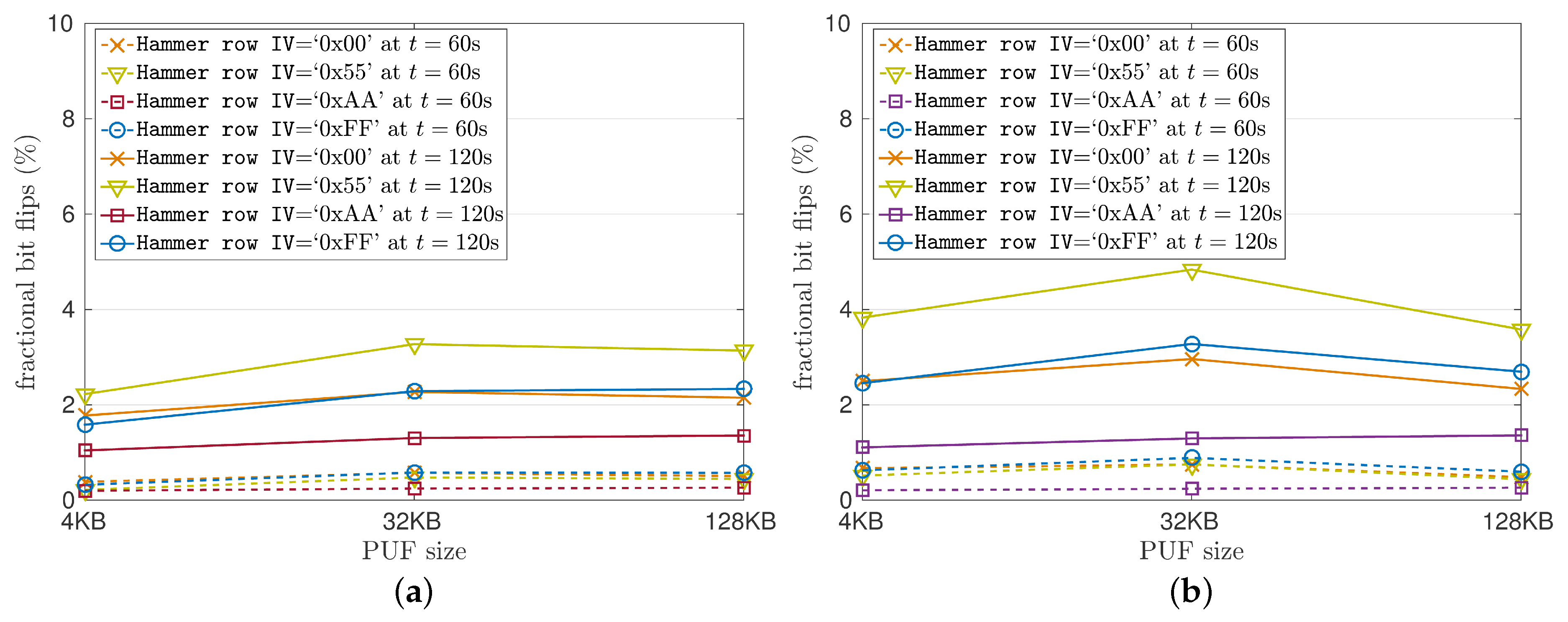
  • Row hammering time: As Figure 4 shows, the RH time significantly affects the amount of bit flips observed in the Row Hammer PUF responses. In particular, for RH time = 120 s, the amount of bit flips observed seems to be, on average, ≈4 times the amount of bit flips observed for RH time = 60 s for all cases examined. A strong relation between the RH time and the amount of bit flips observed was expected. Nevertheless, the exact relation between RH time and the amount of bit flips observed needs to be investigated even further.
  • Row hammering type: While the RH type was expected to have a strong influence on the number of bit flips, Figure 4 clearly indicates that, contrary to expectations, applying DSRH, as shown in Figure 4b, instead of SSRH, as shown in Figure 4a, does not lead to a highly increased number of flips, despite hammering both rows adjacent to each PUF row, instead of just one. Compared to SSRH, using DSHR only leads to ≈9% more bit flips in 60 s and to ≈15% in 120 s on average.
  • PUF size: The PUF size influences the total time required to execute a single iteration of hammering the DRAM. In all implementations presented, each hammer row is accessed roughly every 6 μ s when hammering 2 rows (4 KB PUF) and every 8 μ s when hammering 17 rows (64 KB PUF), when using DSRH, as shown in Figure 2. Figure 4 shows the number of bit flips relative to the PUF size. The number of bit flips does not change significantly for different values of PUF size, i.e., the fraction of bit flips for different memory ranges stays relatively stable.
In addition to these parameters, this work also examines the role of the following two varying factors in the evaluation of the tested Row Hammer PUF implementations:
  • Cache state: Caching can be either enabled or disabled in our experiments. We expect that disabling cache will lead into an increased amount of bit flips observed.
  • Implementation type: The Row Hammer PUF code has been implemented both in firmware and as a kernel module. While the kernel module implementation allows for run-time access to the Row Hammer PUF, we expect this implementation to result in a decrease in the number of bit flips observed, as in this implementation memory accesses are performed using virtual addresses that need to be translated into physical ones, in contrast to the firmware implementation that uses physical addresses. Additionally, we need to note that the PandaBoard has a two-level Translation Lookaside Buffer (TLB) organization, which is used in the translation of virtual memory addresses to physical memory addresses [48].
Finally, we also investigate temperature as a factor that can potentially affect the Row Hammer PUF significantly, as it is known that temperature variations have a strong influence on DRAM retention-based PUFs [1,17,18,20,54].

4.3. PUF Performance Metrics

As already noted, instead of using metrics that are based on the Hamming distance, i.e., inter-device and intra-device Hamming distance, we utilize the Jaccard index [52] for bit flips found in different responses of the same PandaBoard (intra-device Jaccard index— J i n t r a ) or of different PandaBoards (inter-device Jaccard index— J i n t e r ). This is motivated by the fact that the Row Hammer PUF show different characteristics from other memory-based PUFs, such as the SRAM PUF. In particular, the Row Hammer PUF responses draw their PUF characteristics mostly from the location of the flipped bits, and not only from their amount and value. This characteristic, the uniqueness of the flipped cell locations (addresses), is rather not properly reflected by metrics based on the Hamming distance, but by metrics based on the Jaccard index.
In particular, we evaluate the characteristics of both the firmware and the kernel module implementation of the Row Hammer PUF based on the following PUF qualities and the performance metrics relevant to each one of them, as explained below:
  • Uniqueness: The uniqueness of the Row Hammer PUF responses is measured using the J i n t e r metric. This metric compares the indices of bit flips observed in responses obtained from different PUF instances. For two PUF responses obtained from different PUF instances, a set of position indices is created for the bit flip positions of each response. The J i n t e r of these two PUF responses is equal to the cardinality of the intersection of the two sets over the cardinality of their union, using Figure 1. Ideally, for maximal PUF uniqueness, the two responses compared should have no common bit flip locations, resulting in a J i n t e r value equal to zero.
  • Robustness: The robustness of the Row Hammer PUF responses is measured using the J i n t r a metric. This metric compares the indices of bit flips observed in responses obtained from the same PUF instance. For two PUF responses obtained from the same PUF instance, a set of position indices is created for the bit flip positions of each response. The J i n t e r of these two PUF responses is equal to the cardinality of the intersection of the two sets over the cardinality of their union, using Figure 1. Ideally, for maximal PUF robustness, the two responses compared should have the same bit flip locations, resulting in a J i n t r a value equal to one.
  • Entropy: PUF measurements should exhibit sufficient entropy in order to derive a cryptographic key that cannot be easily predicted, either partially or fully. We estimate the Shannon entropy of the PUF measurements, as proposed by Xiong et al. [17]. Therefore, assuming that the locations of flipped bits are distributed uniformly, the entropy can be calculated as:
    H = l o g 2 N k ,
    where N is the total number of bits contained in a PUF response R x , i.e., the PUF size, and k as the cardinality of the set s x that contains the indices of flipped bits observed in R x .

4.4. Evaluation of Our Row Hammer PUF Implementations

To assess the applicability of the set of flipped bits as a PUF, we validated the uniqueness, robustness and entropy of the Row Hammer PUF responses for the parameter sets given in Figure Table 3. In our evaluation, we use four different memory regions, each one located on an individual PandaBoard, with each such memory region considered as a PUF instance. Therefore, four different PandaBoards have been employed for the evaluation of our implementations of the Row Hammer PUF. The PUF address and the PUF size are the same for all of the measurements. Additionally, for each parameter combination, 20 measurements have been taken.
Furthermore, as Table 3 shows, we again examine different values for the hammer row IV and PUF row IV parameters, in order to determine their effects on the responses of the Row Hammer PUF implementations we examine. However, we should note that we do not present results for cases with PUF row IV = ‘0x55’, because we have confirmed that they lead to no bit flips for our PandaBoard implementations. On the contrary, we examine cases where the cache operation is either enabled or disabled. Finally, we also note that we test both the firmware and the kernel module implementation using all the parameter sets given in Table 3.

4.4.1. Regarding the Entropy of the Responses

We again consider a number of different values for the Row Hammer PUF parameters, in order to facilitate comparisons between our implementations and the original implementation by Schaller et al. [1]. To this end, we choose to examine Row Hammer PUF implementations with a fixed PUF size = 128 KB. We believe that, as modern DRAM size ranges from several MB to some GB, the usage of a DRAM region of some hundreds of KB for our implementations of the Row Hammer PUF indicates that this PUF can be implemented even in resource-constrained devices, such as IoT hardware. Nevertheless, as the evaluation of the original implementation of the Row Hammer PUF by Schaller et al. [1] indicates, this PUF can also be implemented using a smaller, or even a larger, memory region. We also choose to examine PUF responses taken at RH time = 60 s and at RH time = 120 s, in order to further facilitate comparisons between our implementations and the original implementation by Schaller et al. [1]. Nevertheless, this PUF can produce responses of adequate uniqueness, robustness and entropy for lower, or even higher, RH time values.
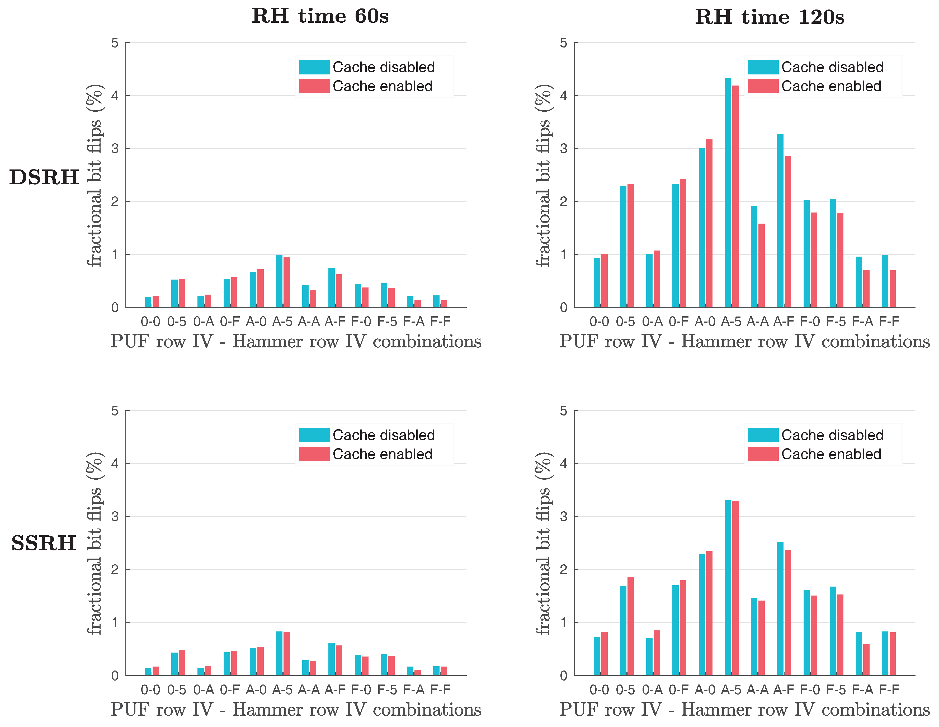
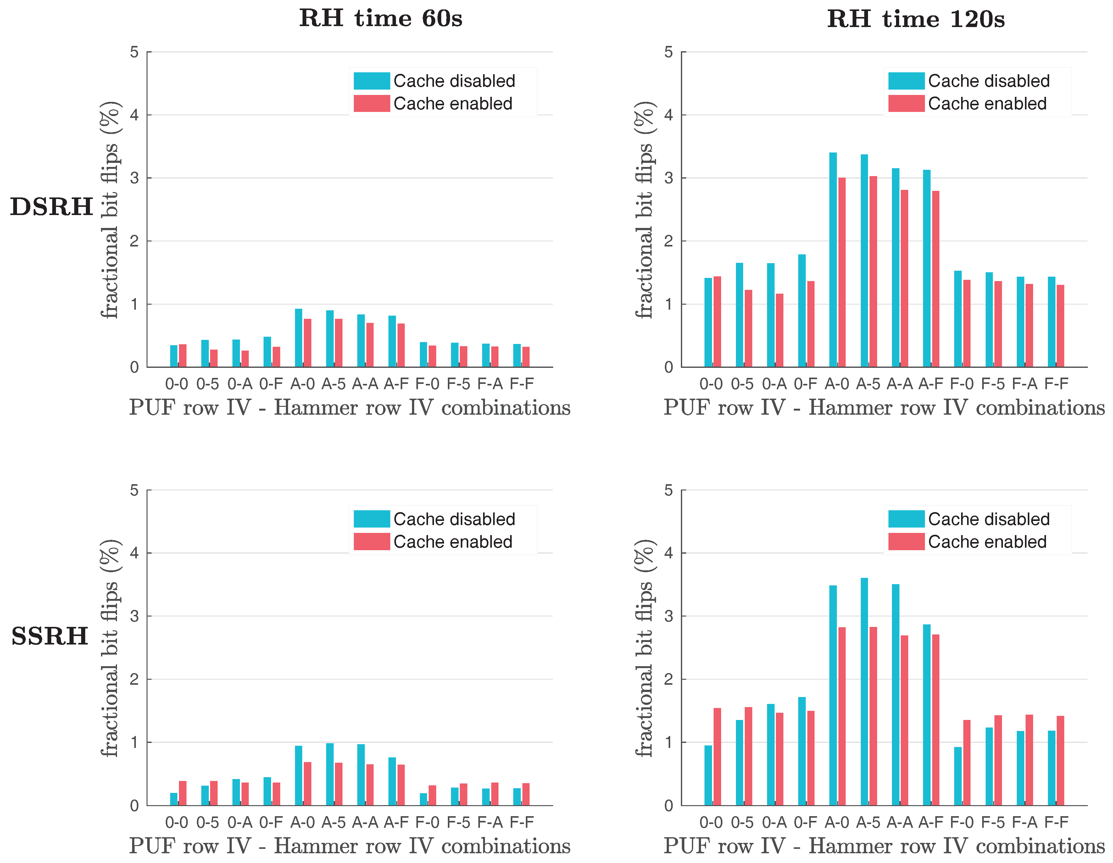
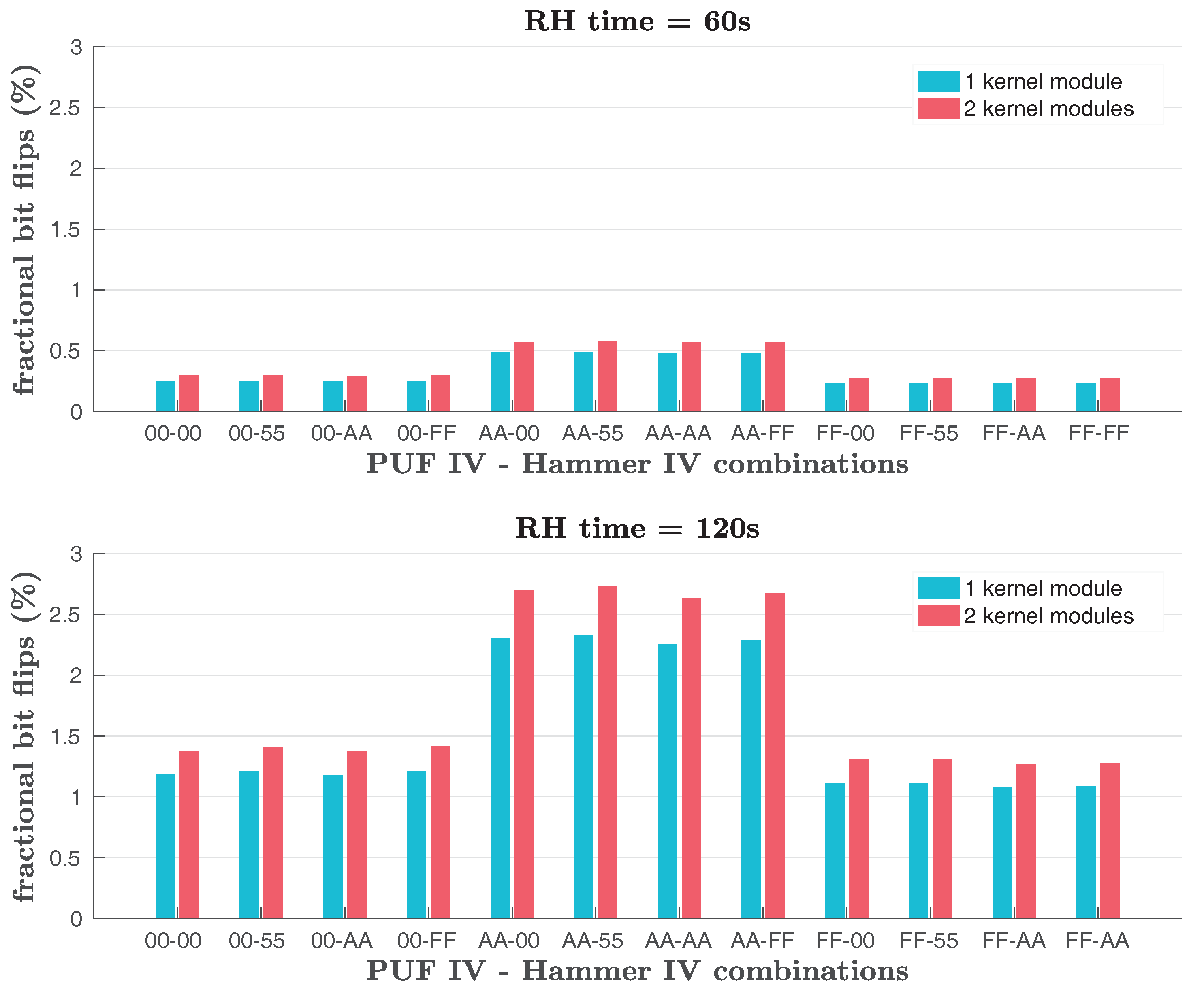
Our results regarding the number of bit flips observed in the responses of our Row Hammer PUF implementations are shown in Figure 6 and Figure 7, for the firmware and the kernel module implementation, respectively. In comparison to the cases presented in Figure 3, for PUF size = 128 KB, RH time = 120 s and (RH type = SSRH/RH type = DSRH), for the original Row Hammer PUF implementation, the same cases in Figure 6 that presents the evaluation results of our firmware implementation, indicate a slight increase in the number of bit flips observed and, therefore, also in the entropy of this implementation.
Additionally, as Figure 6 and Figure 7 show, the average number of bit flips being observed in the Row Hammer PUF responses is rather dependent on the RH time, the hammer row IV and the PUF row IV. In particular, setting RH time = 120 s leads to ≈400% more bit flips than when setting RH time = 60 s. We also note that, in a similar fashion to Figure 3, the largest average number of bit flips and, therefore, the highest entropy occur when hammer row IV = ‘0xAA’ and PUF row IV = ‘0x55’.
On the contrary, the RH type and the Cache state do not appear to affect significantly the number of bit flips being observed in the PUF responses. In particular, the use of DSRH results in slightly more bit flips observed than the use of SSRH. However, the difference in the number of bit flips produced with the two methods does not appear to be significant. Nevertheless, SSRH requires ≈55% less memory and involves less memory accesses compared to DSRH. Furthermore, the Cache being enabled even seems to be increasing the number of bit flips observed for some combinations of hammer row IV and PUF row IV, while, for most cases, disabling the cache operation leads to an increase in bit flips, as we were expecting.
Moreover, the firmware implementation seems to provide more bit flips in comparison to the kernel module implementation, for all cases. This difference is due to the fact that the firmware implementation uses physical addresses to access the DRAM, while the kernel module implementation accesses the DRAM through the use of virtual addresses, which need to be translated into physical ones. This leads to fewer DRAM accesses being achieved by the kernel module implementation for the same RH time and, therefore, the hammer rows being hammered less often, causing fewer bit flips in the PUF rows.
Nevertheless, in all cases, the potential PUF response generation times are significantly lower than the times required to generate the response of existing DRAM retention-based PUFs, using the techniques described by Xiong et al. in [17]. In particular, in comparison to the bit flips caused by the DRAM data retention characteristic alone, we observe, in the best case for each PUF row IV, around twice as many bit flips for our firmware Row Hammer PUF implementation and around 1.35 times as many bit flips for our kernel module Row Hammer PUF implementation, both for RH time = 60 s and for RH time = 120 s, in all cases examined.
We note here that we tested implementations of DRAM retention-based PUFs, based on the techniques described by Xiong et al. in [17], and using all the different PUF row IV described in this work, for both values of RH time employed in this work and for a PUF size = 128 KB. Obviously, for a PUF that does not take advantage of the row hammer effect, such as the DRAM retention-based PUFs that are described by Xiong et al. in [17], the Cache state, the RH type and the hammer row IV are not applicable variables. However, we need to note that since for the Row Hammer PUF implementations, the amount of bit flips observed, for each case, is also dependent on the Cache state, the RH type and the hammer row IV, we only compare the average fractional number of bit flips observed in the responses of DRAM retention-based PUFs, based on the techniques described by Xiong et al. in [17], against the highest average fractional number of bit flips observed in the responses of Row Hammer PUFs, for each particular Row Hammer PUF implementation and PUF row IV described in this work, for both values of RH time employed in this work and for a PUF size = 128 KB, and for results acquired using the same devices for the implementations of both PUF types.
The observed differences in the amount of bit flips generated by the two PUF types, allow us to conclude that for a particular measurement time, the Row Hammer PUF implementations can generate responses of a higher entropy or, in other words, that the Row Hammer PUF implementations can generate responses with a particular amount of bit flips, and, therefore, of a particular entropy, at a lower time of measurement than the other DRAM retention-based PUFs. Nevertheless, this conclusion is applicable only to the values of RH type, Cache state and hammer row IV that provide the highest average fractional number of bit flips, for each particular Row Hammer PUF implementation and PUF row IV described in this work. In such cases, however, we have around 100% more bit flips for our firmware Row Hammer PUF implementation and around 35% more bit flips for our kernel module Row Hammer PUF implementation, both for RH time = 60 s and for RH time = 120 s, than the amount of bit flips observed in the responses of DRAM retention-based PUFs that are implemented according to the techniques described by Xiong et al. in [17], for both measurement times, respectively.
Finally, based on the results shown in Figure 6 and Figure 7, we can easily assume that for hammer row IV = ‘0xAA’ and PUF row IV= ‘0x55’, the minimum fractional number of bit flips observed in the responses of our Row Hammer PUF implementations will be at least 0.25% for RH time = 60 s and 2% for RH time = 120 s, given in percentages relative to PUF size. Based on Figure 2, the fractional Shannon entropy, i.e., the entropy per DRAM cell, is given by the formula:
H b = l o g 2 N k N .
Therefore, the lowest bound for the fractional Shannon entropy, which is an approximation of the min-entropy, for RH time = 60 s, is:
H b = l o g 2 1048576 0.25 100 × 1048576 1048576 0.025 ,
while, for RH time = 120 s, it is:
H b = l o g 2 1048576 2 100 × 1048576 1048576 0.141 .
Therefore, given the vast amount of available cells, the Row Hammer PUF responses show sufficient entropy to derive cryptographic keys. For example, the derivation of a 1024-bit key, given a fractional entropy of 0.025 , requires ≈5 KB, while given a fractional entropy of 0.141 , it requires ≈908 B. Thus, as PUF size = 128 KB, the PUF can create at least 25 1024-bit keys at RH time = 60 s and 144 such keys at RH time = 120 s. Therefore, our Row Hammer PUF implementations can indeed provide cryptographic applications and improved security. We also note that, based on extended experiments, a single 1024-bit key can be constructed in a few seconds. We present here only results for 60 and 120 s, in order to make our results somehow comparable to those of the original Row Hammer PUF implementation presented by Schaller et al. [1], and demonstrate that our implementations can provide a significant amount of cryptographic keys within a few minutes, allowing in this way for cryptographic applications that require more than a single key.

4.4.2. Regarding the Robustness and Uniqueness of the Responses

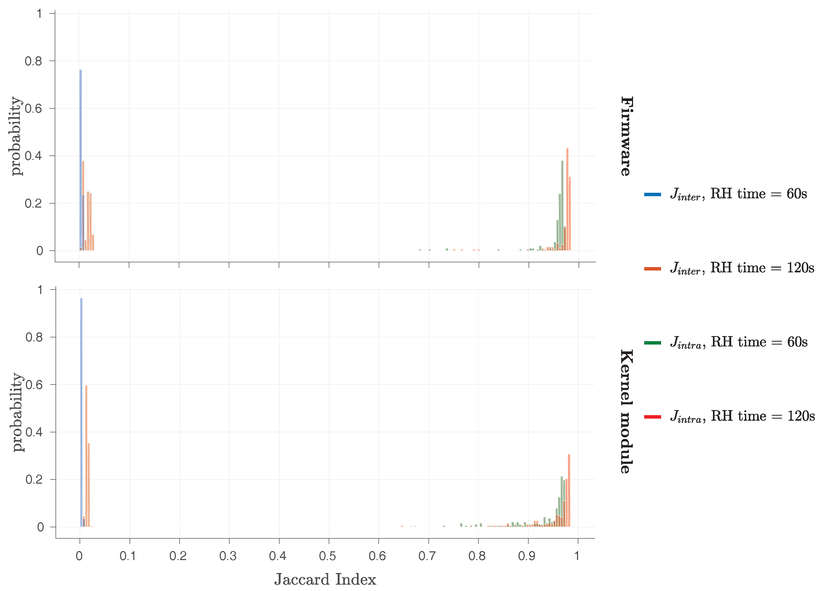
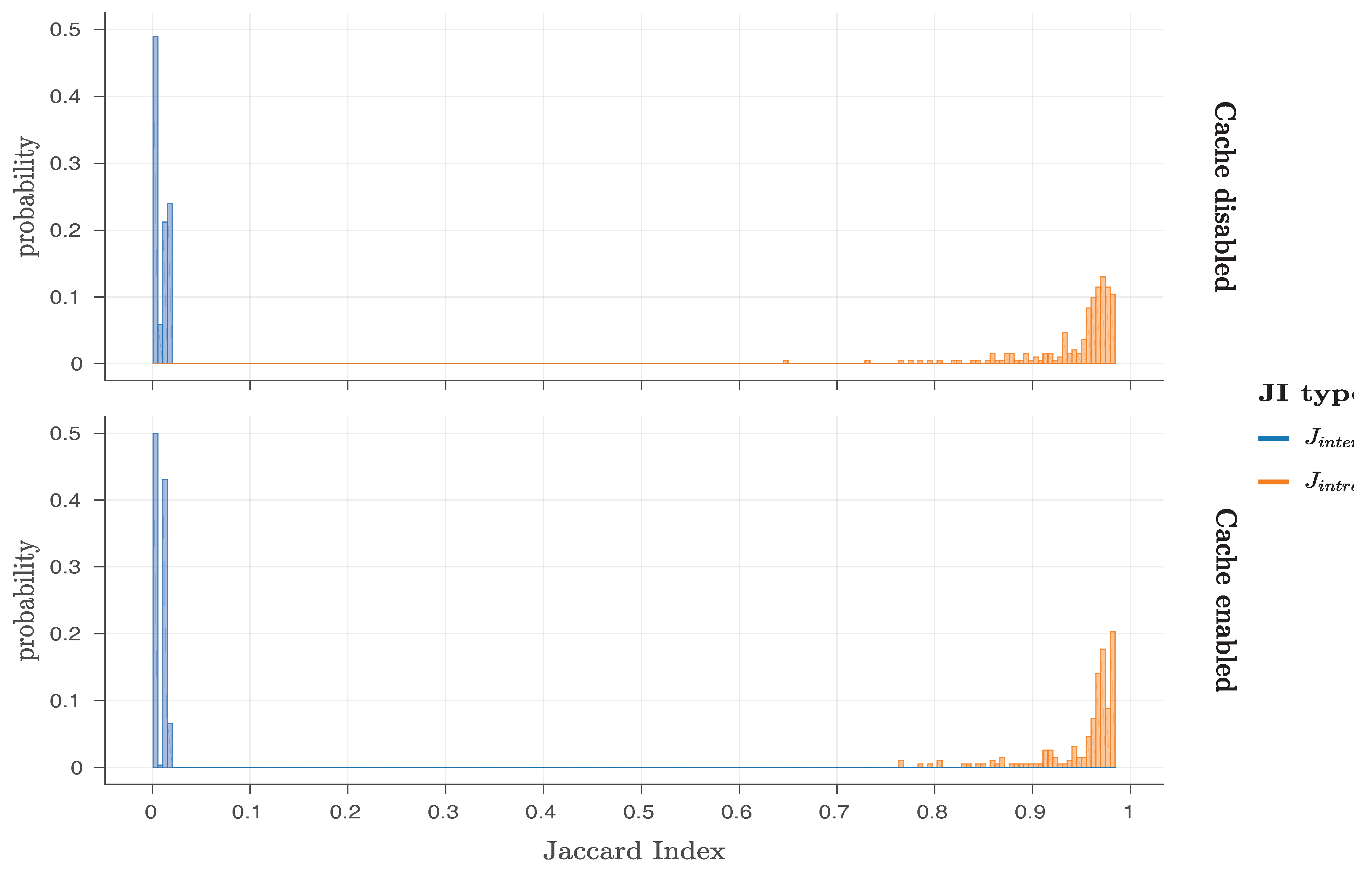
In a similar fashion to the original work by Schaller et al. [1], we also consider the J i n t r a and J i n t e r metrics, in order to assess the robustness and uniqueness, respectively, of the responses of our Row Hammer PUF implementations. As Figure 8 shows, the Row Hammer PUF responses of both the firmware and the kernel module implementation exhibit a high degree of robustness and uniqueness, as, for both cases, the J i n t r a values are close to 1 and the J i n t e r values close to zero, in a similar fashion to Figure 5. However, we need to note that our results consider all cases for the different parameter values shown in Table 3, and not just the different cases for hammer row IV = ‘0xAA’ and PUF row IV = ‘0x55’.
As the values of J i n t r a and J i n t e r are not overlapping in any case, we can conclude that all Row Hammer PUF instances can be robustly and uniquely identified. Nevertheless, we note that in Figure 8, J i n t r a values for RH time = 120 s are closer to one and J i n t e r values for RH time = 60 s closer to zero, in a similar fashion to Figure 5. Such a result should be expected, due to the larger number of bit flips observed at RH time = 120 s in comparison to RH time = 60 s.
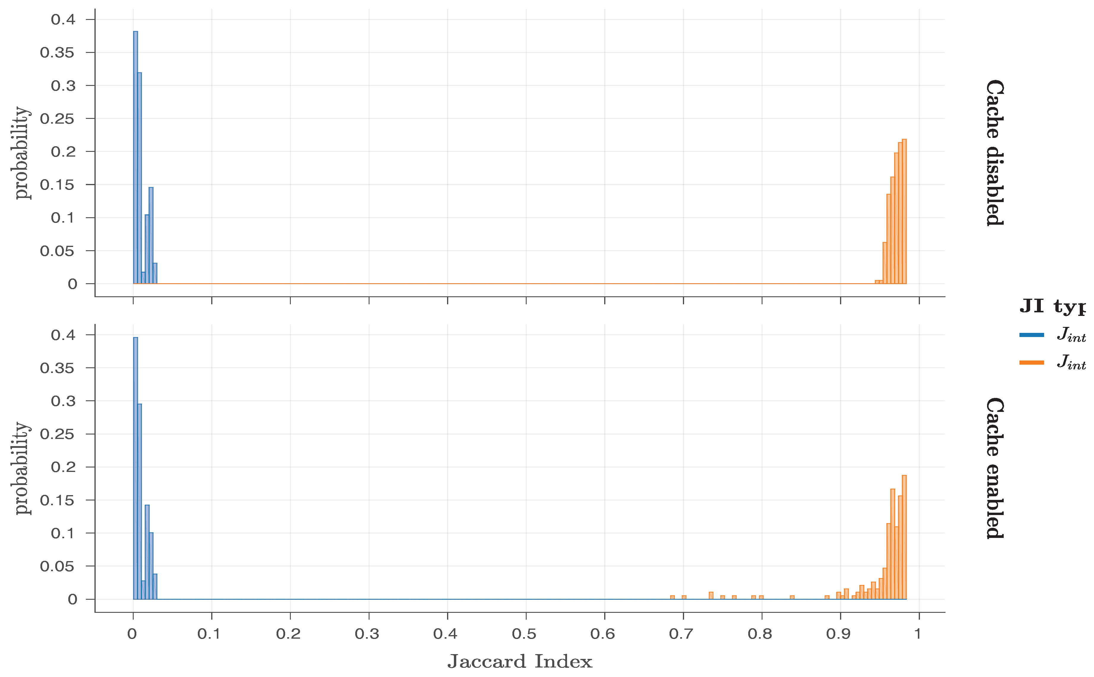
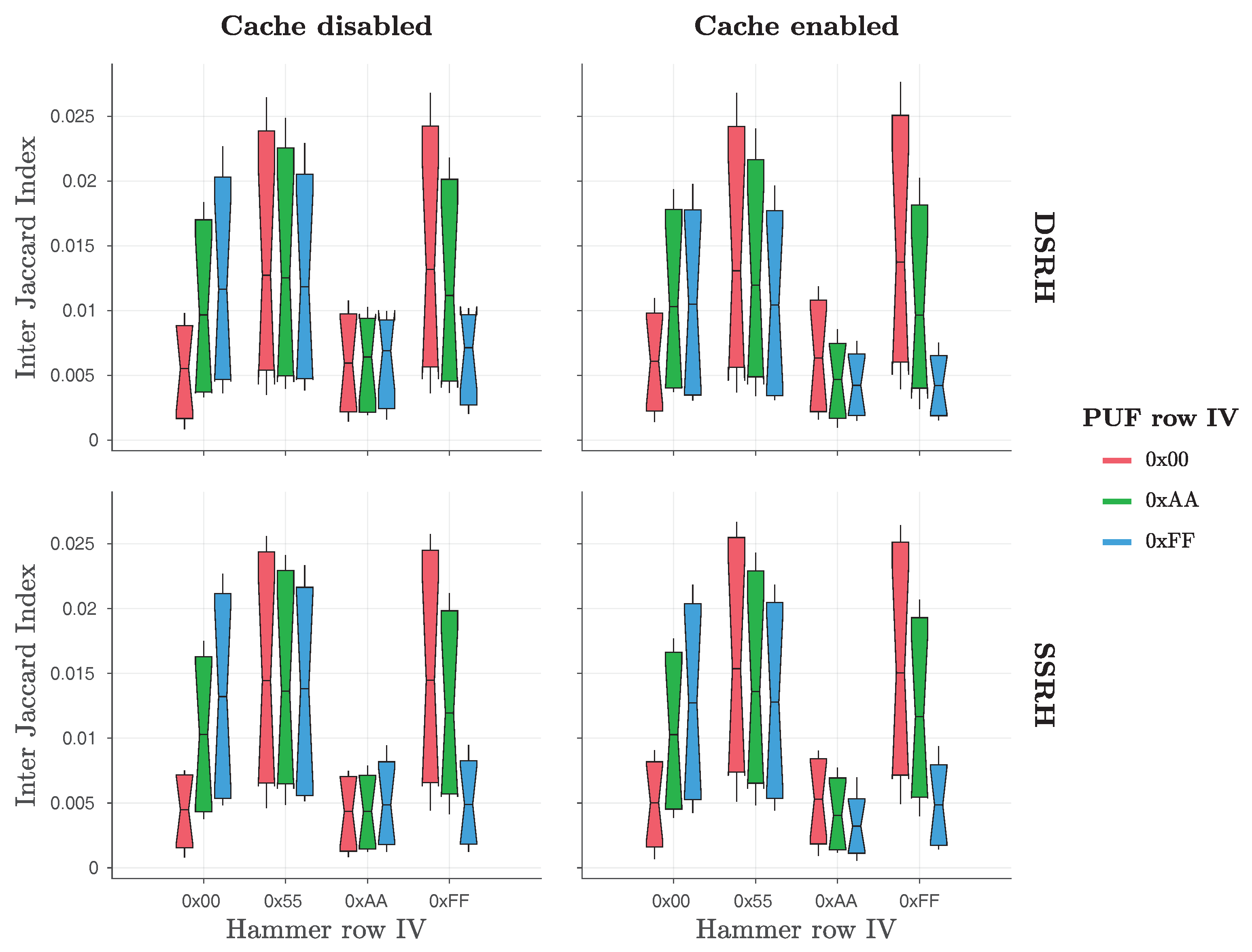
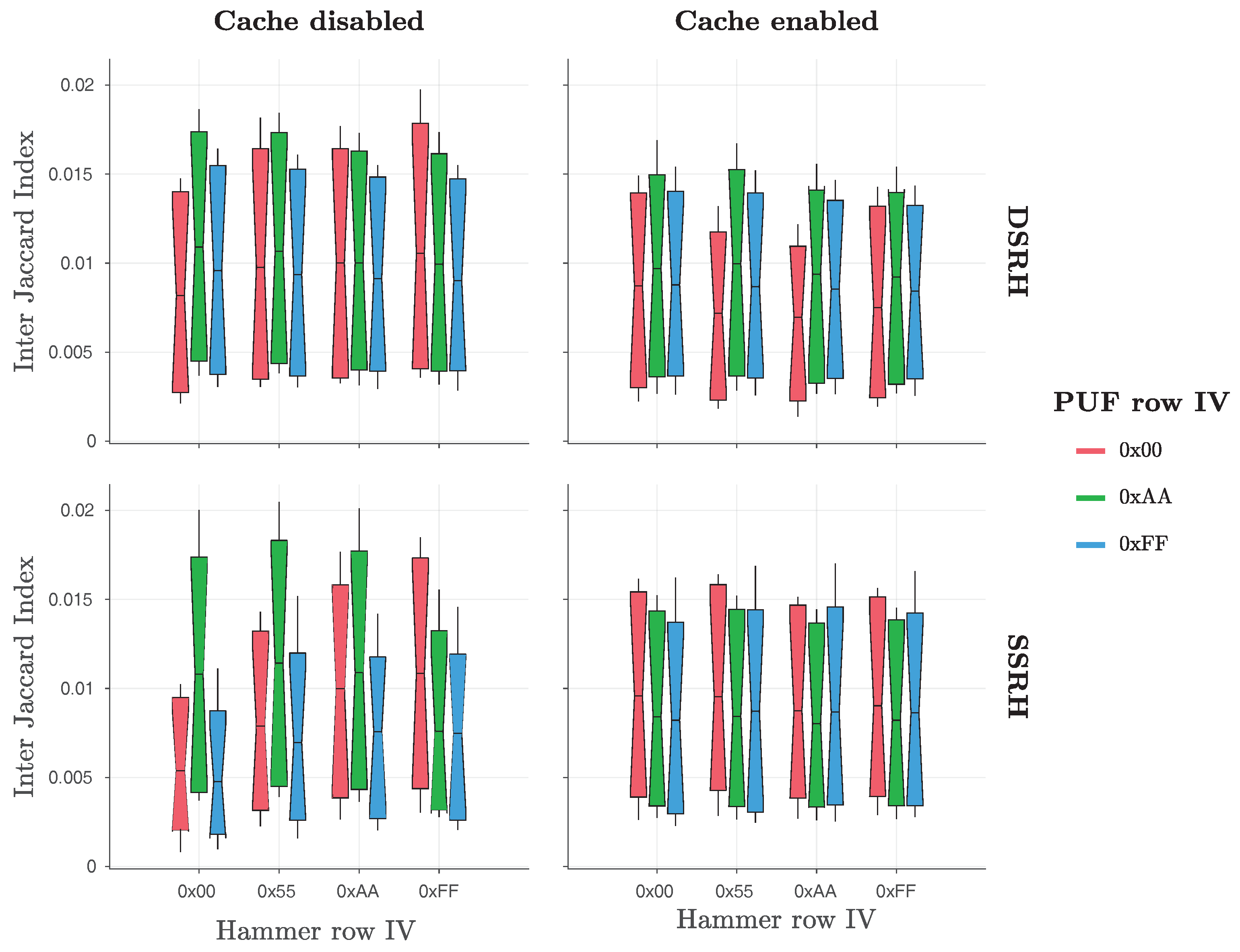
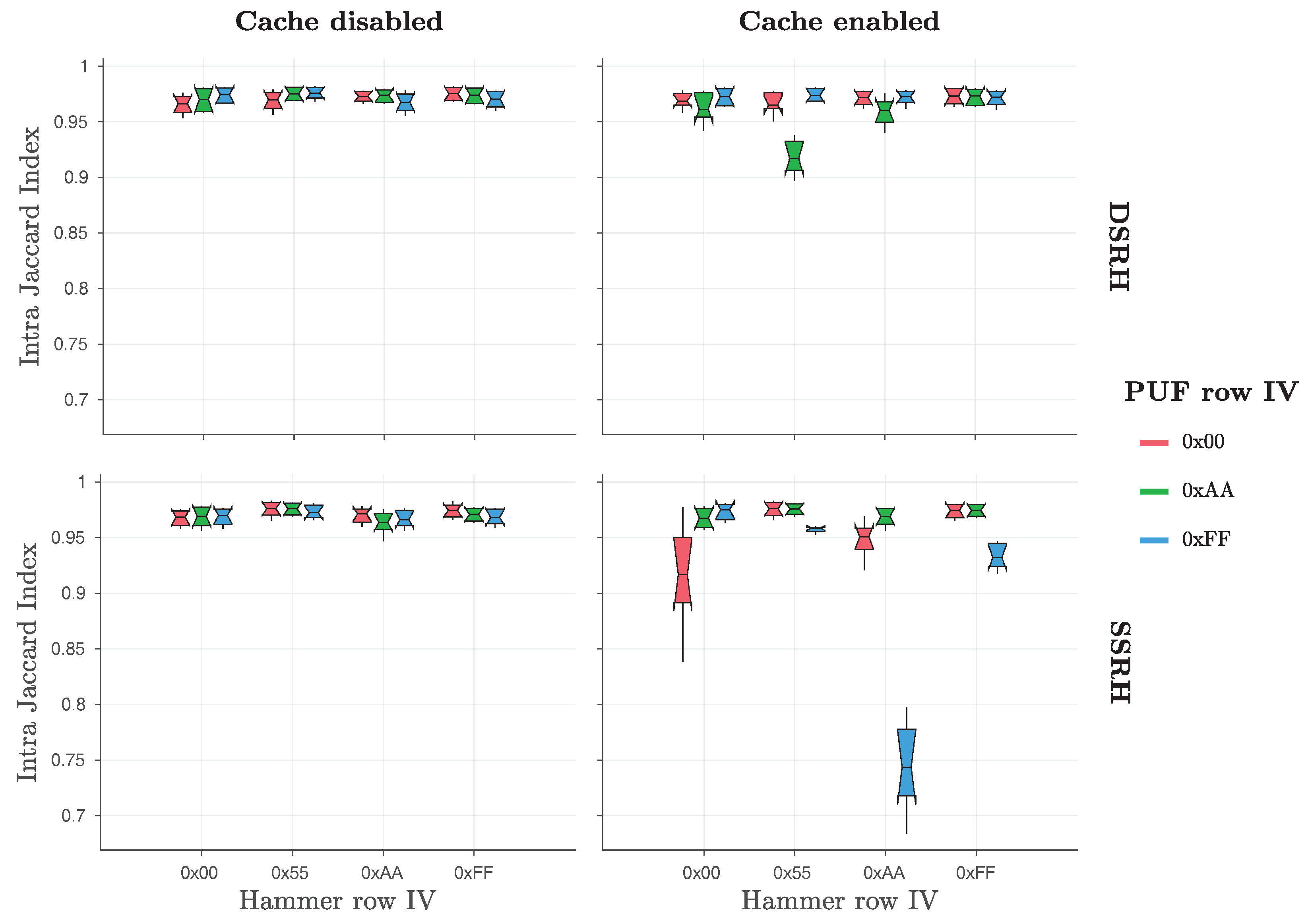
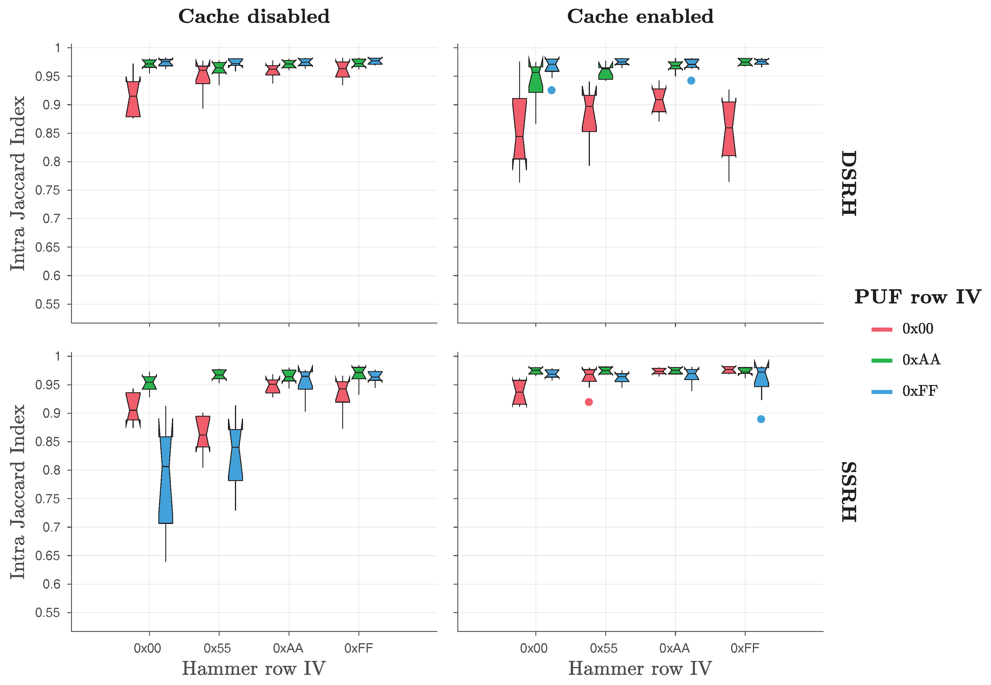
Furthermore, Figure 9 and Figure 10 present in more detail the J i n t r a and J i n t e r values for all cases considered, for the firmware and the kernel module implementation, respectively. These two Figures also clearly indicate that for both implementations as well as both Cache states, all the Row Hammer PUF instances can be robustly and uniquely identified. Additionally, we note that, in most cases, a few outliers exist for J i n t r a values, which could potentially be ignored.
To address the nature of these outliers, we present Figure 11 and Figure 12, which show the distributions of J i n t e r values, grouped by hammer row IV, for different PUF row IV, Cache states and RH type, for the firmware and the kernel module implementation, respectively, and Figure 13 and Figure 14, which show the distributions of J i n t r a values, grouped by hammer row IV, for different PUF row IV, Cache states and RH type, for the firmware and the kernel module implementation, respectively. In these Figures, the values of J i n t e r and J i n t r a for different RH time are grouped in a single distribution.
As one can see in Figure 11, the lowest J i n t e r values for the firmware implementation seem to occur for hammer row IV = ‘0xAA’, in all cases. However, Figure 12 indicates that J i n t e r values for the kernel module implementation seem to be similar for all hammer row IV values, in all cases. Furthermore, Figure 13 indicates that all J i n t r a values for the firmware implementation are close to one, apart from some values for RH type = SSRH, with the cache operation enabled. On the contrary, Figure 14 shows that J i n t r a values for the kernel module implementation are more noisy in all cases, with the highest J i n t r a values for this implementation occurring for hammer row IV = ‘0xAA’, in all cases.
Figure 13 and Figure 14 both include values near 0.7 , which do not appear to be clear outliers, indicating that the usual error correction schemes may not be applicable for the stabilisation of all the responses of the firmware and kernel module implementations. We, therefore, propose the application of the helper data scheme proposed by Schaller et al. [18] for the error correction of such cases. However, for hammer row IV = ‘0xAA’ and PUF row IV = ‘0x55’/‘0xAA’, the minimum J i n t r a values seem to be under 0.9 , in all cases, and therefore, their noise can be easily corrected by standard Fuzzy Extractor (FE) constructions [53].
Finally, as 20 measurements were performed for each combination of parameters, we have utilised an analysis method for the variance of these repeated measurements, based on the work of Bakeman [55]. We utilise an ANalysis Of VAriance (ANOVA) method, in order to discover the parameters that have the strongest effects on our results. We, therefore, consider only significant and large factor effects as meaningful. Our effect size is calculated as generalized eta-squared ( η G 2 ), based on the work of Bakeman [55], with values of η G 2 > 0.26 denoting strong effects, i.e., factors accounting for more than 26% of the data variance.
For J i n t e r values, ANOVA reveals that both the hammer row IV and the PUF row IV have a significant effect on them. In particular, for the firmware implementation, ANOVA, based on the method suggested by Bakeman [55], indicates that the hammer row IV has the strongest effect ( F ( 3 , 15 ) = 229.53 , p < 0.001 , η G 2 = 0.96 ) on the J i n t e r values, while the PUF row IV also has a significant effect ( F ( 2 , 10 ) = 30.93 , p < 0.001 , η G 2 = 0.53 ) on them, as well as the interaction between the two sets of initial values ( F ( 6 , 30 ) = 220.43 , p < 0.001 , η G 2 = 0.93 ). For the kernel module implementation, ANOVA indicates that the PUF row IV has the strongest effect ( F ( 2 , 10 ) = 27.02 , p < 0.001 , η G 2 = 0.78 ) on the J i n t e r values, while the hammer row IV also has a significant effect ( F ( 3 , 15 ) = 24.37 , p < 0.001 , η G 2 = 0.31 ) on them, as well as the interaction between the two sets of initial values ( F ( 6 , 30 ) = 55.15 , p < 0.001 , η G 2 = 0.73 ).
For J i n t r a values, ANOVA also reveals that both the hammer row IV and the PUF row IV have a significant effect on them. In particular, for the firmware implementation, ANOVA, based on the method suggested by Bakeman [55], indicates that the hammer row IV has the strongest effect ( F ( 3 , 9 ) = 56.37 , p < 0.001 , η G 2 = 0.88 ) on the J i n t r a values, while the PUF row IV also has a significant effect ( F ( 2 , 6 ) = 132.51 , p < 0.001 , η G 2 = 0.79 ) on them, as well as the interaction between the two sets of initial values ( F ( 6 , 18 ) = 92.36 , p < 0.001 , η G 2 = 0.94 ). For the kernel module implementation, ANOVA indicates that the PUF row IV has the strongest effect ( F ( 2 , 6 ) = 21.46 , p = 0.002 , η G 2 = 0.63 ) on the J i n t r a values, while the hammer row IV also has a significant effect ( F ( 3 , 9 ) = 38.23 , p < 0.001 , η G 2 = 0.51 ) on them. In this case, the interaction between the two sets of initial values does not seem to have a meaningful effect ( F ( 6 , 18 ) = 1.33 , p = 0.293 , η G 2 = 0.23 ) on the J i n t r a values.
These results seem mostly consistent with the results shown in the different Figures. However, the difference in the ANOVA values for the J i n t r a and J i n t e r metrics for the two implementations under examination, as well as the visible variations in the values presented in Figure 11, Figure 12, Figure 13 and Figure 14 indicate that there is another factor that significantly affects the values for these two metrics.

4.5. Extended Investigation of the Role of Temperature on the Responses of the Row Hammer PUF

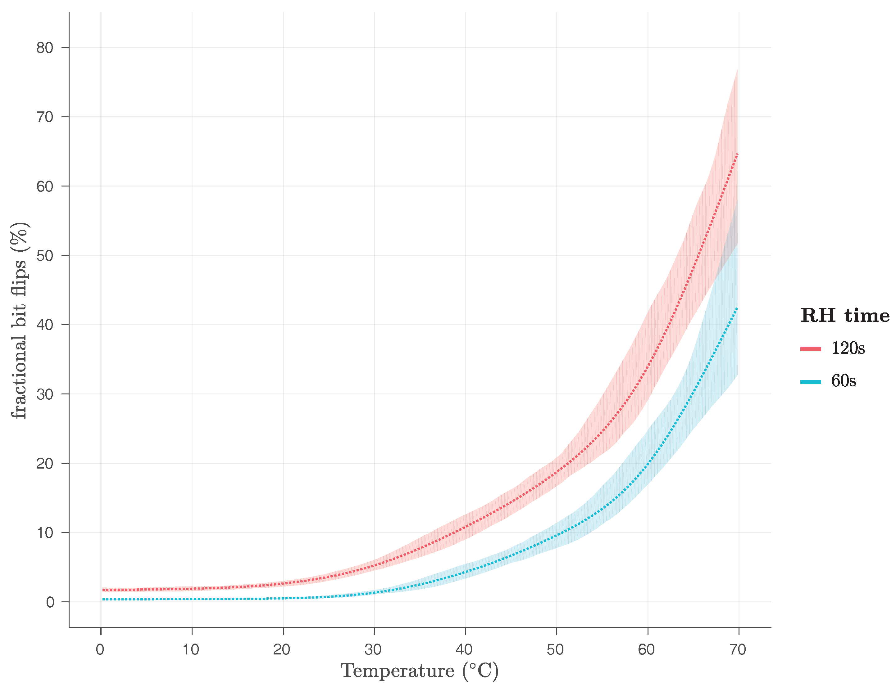
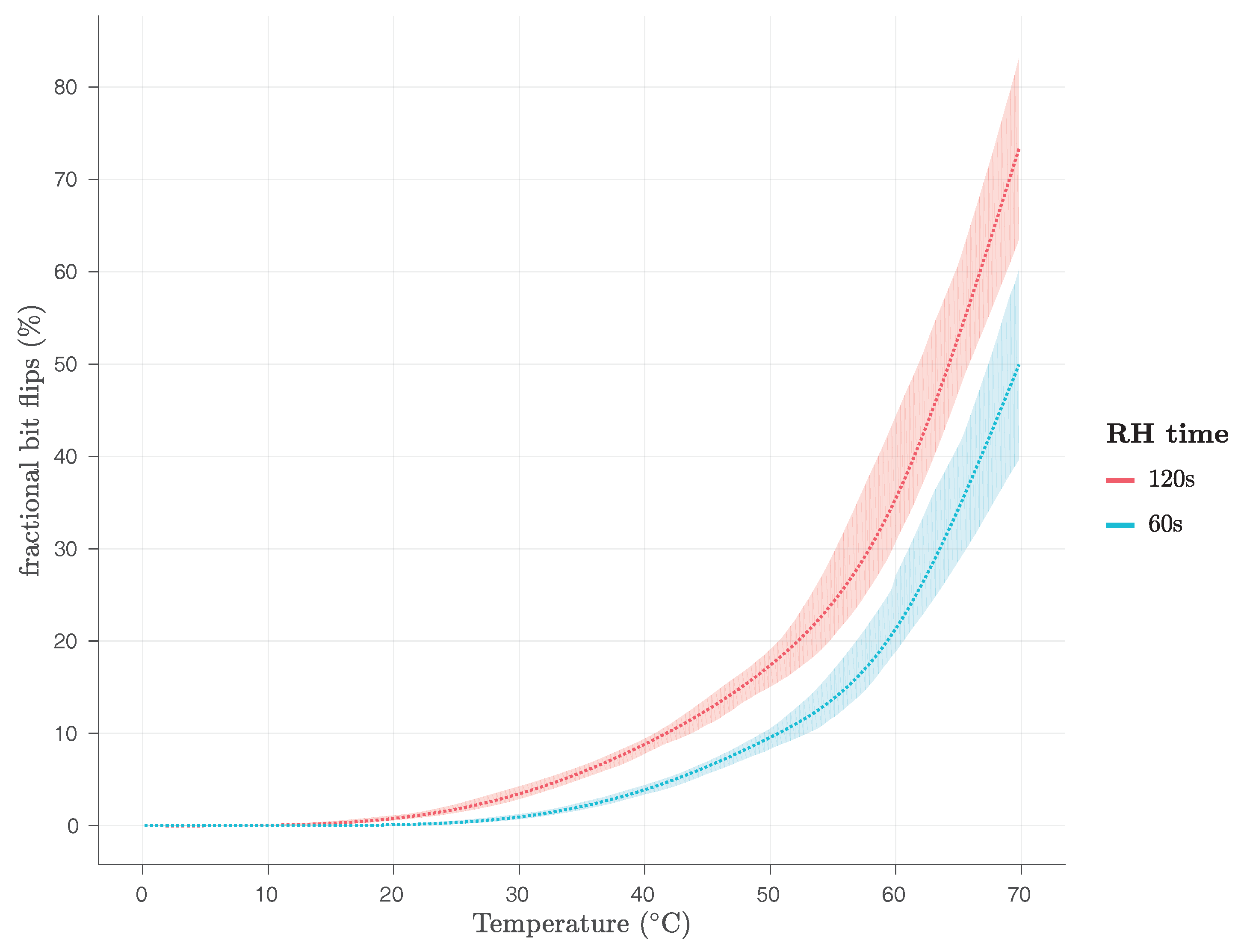
The original paper by Schaller et al. [1] recognised that the original Row Hammer PUF responses could be influenced by its operating temperature. Therefore, it examined the behaviour of the original Row Hammer PUF at different levels of its operating temperature, namely 40 C (working temperature of DRAM on PandaBoard), 50 C and 60 C. Schaller et al. [1] presented the average number of bit flips and the J i n t r a values for PUF responses taken at these respective temperatures, as shown in Table 4.
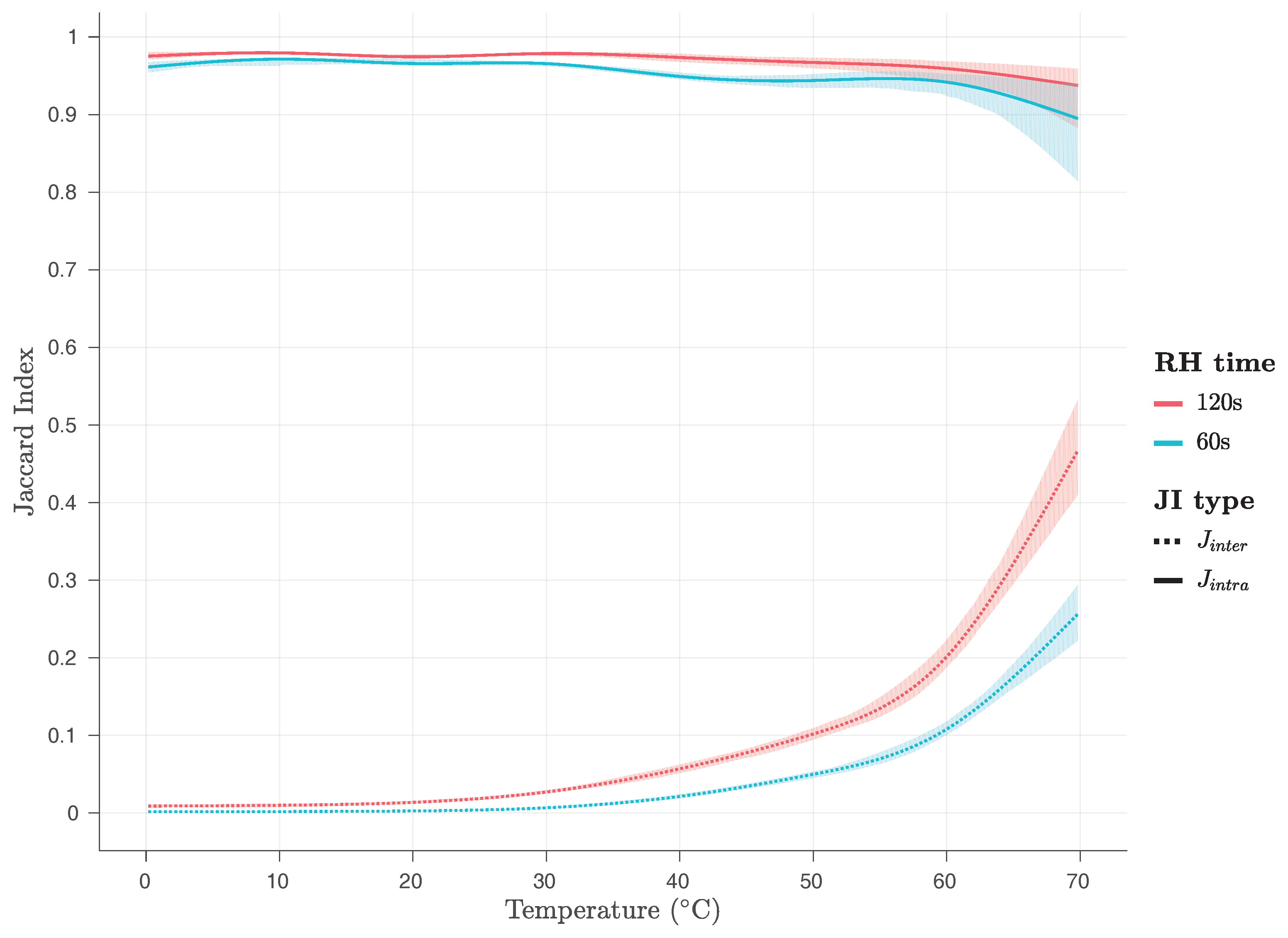
Nevertheless, the original work by Schaller et al. [1] does not present any J i n t r a values calculated for two responses that have been taken at different temperatures from each other. As we will show, this might have been a major shortcoming of this work, as responses taken from the same Row Hammer PUF at different temperatures from each other differ significantly and Row Hammer PUF instances cannot be robustly and uniquely identified based on them. Nevertheless, as Schaller et al. [1] indicate, while bit flips increase at higher temperatures, the noise level stays constant at different temperatures, when the temperature is stable. Therefore, the Row Hammer PUF exhibits sufficient stability to be used at any temperature, within its physical limits, as long as the temperature remains stable.
Our evaluation results show that even small changes in the ambient temperature of the Row Hammer PUF can have dramatic effects on its responses. In particular, two responses taken from the same Row Hammer PUF instance at two temperatures differing by only 10 C cannot, in general, be used to identify that instance in a robust way and, sometimes, cannot even be used to uniquely identify such an instance. However, in order to validate that our Row Hammer PUF implementations can be used at different temperatures, when the temperature remains stable, we utilise the same methodology as Schaller et al. [1] and present how temperature variations affect the average fractional number of bit flips observed in the responses of both the firmware, in Figure 15 and the kernel module implementation, in Figure 16.
We have evaluated both the firmware and the kernel module Row Hammer PUF implementations in the region from 0 C to 70 C using the ambient temperature and without reading out the exact operating temperature of the DRAM module. We performed our experiments using a climate chamber, namely a Heraeus Vötsch HC4005, which has an absolute accuracy of ± 0.8 C. We have also performed experiments for both Row Hammer PUF implementations at 80 C of ambient temperature, at which temperature, however, the PandaBoard becomes unstable and either resets itself or, even, its execution hangs, until the PandaBoard is manually reset.
As Figure 15 and Figure 16 show, for RH time = 60 s, the average fractional number of bit flips is close to 0% of the PUF size for 0 C, for both implementations, and only starts rising after the temperature has risen beyond 20 C, reaching 50% of the PUF size, for the firmware implementation, and more than 40% of the PUF size, for the kernel module implementation, at 70 C. As Figure 15 and Figure 16 also show, for RH time = 120 s, the average fractional number of bit flips is very close to 0% of the PUF size, for the kernel module implementation, and slightly above 2% of the PUF size, for the firmware implementation, for 0 C. The average fractional number of bit flips starts rising slightly before 20 C, for both implementations, reaching more than 60% of the PUF size, for the firmware implementation, and more than 70% of the PUF size, for the kernel module implementation, at 70 C.
This is a clear indication that both Row Hammer PUF implementations may face uniqueness problems for low RH time and low temperatures, as not enough bit flips will be occurring, and also for high RH time and high temperatures, as too many bit flips will be occurring, potentially preventing in both cases the correct identification of the PUF instance.
Additionally, we have examined the effects of temperature variations on the J i n t r a and J i n t e r values at various temperatures, as shown in Figure 17 and Figure 18, for the firmware and the kernel module, respectively. As it can be seen on Figure 17 and Figure 18, the values of the J i n t r a metric are close to 1 for both implementations and all temperatures examined, while the values of the J i n t e r metric are close to zero for both implementations and temperatures below 60 C, being below 0.1 for temperatures below 50 C, and below 0.2 for temperatures between 50 C and 60 C. However, for temperatures between 60 C and 70 C, they rise abruptly and they reach, for RH time = 60 s, values close to 0.25, for the firmware, and close to 0.35 for the kernel module implementation, and, for RH time = 120 s, values close to 0.45, for the firmware, and close to 0.6 for the kernel module implementation.
This is a clear indication that both Row Hammer PUF implementations may face uniqueness problems for high RH time and high temperatures, as the J i n t e r values reach closer to the J i n t r a ones, surpassing even the value of 0.5, and, therefore, potentially preventing in both cases the correct identification of the PUF instance.
Furthermore, as 20 measurements were performed for each combination of parameters for every 10 C, in the temperature region from 0 C to 70 C, we have utilised an analysis method for the variance of these repeated measurements, based on the work of Bakeman [55]. We utilise this ANalysis Of VAriance (ANOVA) method, in order to discover the parameters that have the strongest effects on our results. We, therefore, consider only significant and large factor effects as meaningful. Our effect size is calculated as generalized eta-squared ( η G 2 ), based on the work of Bakeman [55], with values of η G 2 > 0.26 denoting strong effects, i.e., factors accounting for more than 26% of the data variance.
Our ANOVA analysis, in general, reveals that indeed temperature has a profound effect on both J i n t r a and J i n t e r values. However, it has a larger effect on the J i n t e r values—with F ( 7 , 35 ) = 229.41 , p < 0.001 , η G 2 = 0.98 , for the firmware, and F ( 7 , 35 ) = 253.43 , p < 0.001 , η G 2 = 0.98 , for the kernel module implementation—than on the J i n t r a values—with F ( 7 , 21 ) = 3.50 , p = 0.012 , η G 2 = 0.54 , for the firmware, and F ( 7 , 21 ) = 14.40 , p < 0.001 , η G 2 = 0.83 , for the kernel module implementation.
Moreover, our results regarding pairwise comparisons for J i n t e r values, produced using the Student’s t-tests with pooled standard deviation and adjusted using the Holm–Bonferroni method, reveal significantly lower p-values for 60 C and 70 C compared to all other groups, for the J i n t e r values of the responses of both implementations, while p-values for 50 C compared to groups for 0 C, 10 C, 20 C and 30 C also appear low, for the J i n t e r values of the responses of both implementations. Furthermore, pairwise comparisons for J i n t r a values, produced using the Student’s t-tests with pooled standard deviation and adjusted using the Holm–Bonferroni method, reveal low p-values for 70 C compared to all other groups, for the J i n t r a values of the responses of the firmware implementation, and p-values for 0 C and 10 C compared to groups for 20 C, 30 C, 40 C and 50 C, 60 C and 70 C appear low, for the J i n t r a values of the responses of the kernel module implementation. These results seem to be verified by the appearance and form of Figure 17 and Figure 18.
Finally, we have also evaluated, for both implementations, the J i n t r a for pairs of Row Hammer PUF responses taken at different temperatures from the same device. Figure 19 presents the J i n t r a for pairs of responses taken at 20 C and responses taken at the same or different temperatures from each other. As one can see in this Figure, while J i n t r a values are very close to one for pairs of responses taken both at 20 C, J i n t r a values for pairs of responses taken at different temperatures from each other are all well below 0.3, indicating that the two responses will rather be recognised as coming from different devices, while in fact they have been produced from the same device. This is a very clear indication that both Row Hammer PUF implementations are facing robustness problems when the ambient temperature changes, even for small temperature variations of 10 C and, therefore, can only be robustly identified when PUF responses taken at the same temperature are used.
As this section shows, temperature can significantly influence the responses of the Row Hammer PUF, affecting both their robustness, in general, as well as their uniqueness, in some cases. We can, therefore, assume that minor variations observed for room temperature measurements could be caused by small variations in the ambient temperature. However, we have also shown that the Row Hammer PUF can be used over a large range of ambient temperature values, as long as the temperature remains the same. Nevertheless, even in this case, it is uncertain whether it will operate sufficiently at very low temperatures, at which, apart from the long time periods that may be required for responses to be generated, also data remanence effects can start to affect its operation [56]. As we have discussed uniqueness problems may appear both at very low temperatures for low RH time, as not enough bit flips may be occurring, and at high temperatures for high RH time, as too many bit flips may be occurring. In the latter case, we could use the indices of the cells that have not yet flipped, which could provide unique identification of different devices. In conclusion, however, we need to state that the temperature dependency of the Row Hammer PUF is an issue that will need to be adequately addressed, before this PUF can be considered as an efficient security mechanism for widespread usage. We do need to note that our experiments were based on different values of the ambient temperature, a characteristic that an attacker can very easily manipulate, and not on the operating temperature of the PUF itself.

4.6. Potential Statistical Relations among PUF Cells

In this section, we examine whether there is some statistical relation between the PUF cells that flip and their neighbourhood. We examine whether there is a statistical relation between PUF cells that have flipped and the values of their neighbouring PUF cells and also whether there is a statistical relation between PUF cells that have flipped and other PUF cells in their neighbourhood that also flip for the same or a lower RH time value. In particular, we examine the probability that PUF cells nearby a bit flip have a specific value and the probability that such cells have flipped at the same or a lower RH time value. If any of these probabilities are significantly higher than the relevant average probability for all the PUF cells, then we can conclude that some statistical relation exists. Otherwise, we can conclude that no statistical relation seems to exist among the PUF cells that flip and their neighbouring PUF cells.
In this way, we can investigate whether there is some way to predict the positions of the bit flips or if they appear to be random. If the positions of the bit flips could be predicted, then a number of different attacks taking advantage of this property may have been possible. However, in all cases, our results show that there appears to be no statistical relation between the PUF cells that flip and their neighbourhood. Nevertheless, a more in-depth investigation would be required, before we could state with absolute certainty that such a relation does not exist.
First, we examine the average values of PUF cells around a PUF cell that has flipped, for room temperature, PUF size = 128 KB, RH time = 120 s, hammer row IV = ‘0x55’ and PUF row IV = ‘0xAA’ and all the different combinations of cache states and RH type, as shown in Table 5 and Table 6, for the firmware and the kernel module implementation, respectively. In this way, we can detect potential statistical relations affecting the response of the PUF that stem from interactions between the charge that was stored in a PUF cell that has flipped, i.e., that has had at least half of its charge leaked, and the charge stored in other PUF cells found in different rows and columns of the DRAM around the flipped PUF cell. We do so by using a 3 × 3 window having the flipped PUF cell in its centre every time. Of course, only cells in the same row of this window are adjacent to each other in the DRAM module, as PUF cells in different rows may be separated by a hammer row in the DRAM module. Our results, which are shown in Table 5 and Table 6, indicate that the average probability of a neighbouring PUF cell having a logical value of one or zero is close to 50% in all cases, suggesting a lack of any statistical relation between these values and the fact that the center cell of the window has flipped. We test for RH time = 120 s only, as the PUF cells that have flipped for RH time = 60 s are a subset of the PUF cells that have flipped for RH time = 120 s.
Subsequently, we examine the average probability that a PUF cell has flipped in the neighbourhood of another PUF cell that has flipped, for room temperature, PUF size = 128 KB, RH time = 120 s, hammer row IV = ‘0x55’ and PUF row IV = ‘0xAA’ and all the different combinations of cache states and RH type, as shown in Table 7 and Table 8, for the firmware and the kernel module implementation, respectively. In this way, we can detect potential statistical relations affecting the response of the PUF that stem from interactions between the charge that was stored in a PUF cell that has flipped, i.e., that has had at least half of its charge leaked, and the charge of other PUF cells found in different rows and columns of the DRAM in an extensive region around the flipped PUF cell, leading these other PUF cells to decay faster than usual, and, therefore, also be flipped. We do so by using a 7 × 7 window having the flipped PUF cell in its centre every time. Of course, only cells in the same row of this window are adjacent to each other in the DRAM module, as PUF cells in different rows may be separated by a hammer row in the DRAM module. Our results, which are shown in Table 7 and Table 8, indicate that the average probability of a PUF cell being flipped in the extended neighbourhood considered is consistently similar to the general probability of a PUF cell being flipped at RH time = 120 s, for each case, as shown in Figure 6 and Figure 7, for the firmware and the kernel module implementation, respectively. Therefore, our results suggest a lack of any statistical relation between PUF cells that flip within a particular RH time. We test for RH time = 120 s only, as the PUF cells that have flipped for RH time = 60 s are a subset of the PUF cells that have flipped for RH time = 120 s.
Finally, we also examine the average probability that a PUF cell that has flipped within RH time = 60 s is in the neighbourhood of another PUF cell that has flipped within RH time = 120 s, for room temperature, PUF size = 128 KB, hammer row IV = ‘0x55’ and PUF row IV = ‘0xAA’ and all the different combinations of cache states and RH type, as shown in Table 9 and Table 10, for the firmware and the kernel module implementation, respectively. In this way, we can detect potential statistical relations affecting the response of the PUF that stem from interactions between the charge that was stored in a PUF cell that has flipped, i.e., that has had at least half of its charge leaked, within RH time = 120 s and the charge of other PUF cells, found in different rows and columns of the DRAM in an extensive region around the flipped PUF cell, that have flipped, i.e., that have had at least half of its charge leaked, within RH time = 60 s and, therefore, may have also affected the decay of the PUF cell that has flipped within RH time = 120 s. We do so by using a 7 × 7 window having the PUF cells that flip within RH time = 120 s in its centre every time. Of course, only cells in the same row of this window are adjacent to each other in the DRAM module, as PUF cells in different rows may be separated by a hammer row in the DRAM module. Our results, which are shown in Table 9 and Table 10, indicate that the average probability of a PUF cell having flipped within RH time = 60 s and at the same time being in the neighbourhood of another PUF cell that has flipped within RH time = 120 s is consistently similar to the general probability of a PUF cell being flipped at RH time = 60 s, for each case, as shown in Figure 6 and Figure 7, for the firmware and the kernel module implementation, respectively. Therefore, our results suggest a lack of any statistical relation between PUF cells that flip at a particular RH time = t 1 and PUF cells that flip at another particular RH time = t 2 , with t 1 < t 2 .
Thus, our results indicate that the logical values—and, therefore, also the charges—and the retention times of victim cells in a DRAM utilised for the implementation of the Row Hammer PUF do not affect the retention times of other victim cells in that DRAM, while it is being employed as a Row Hammer PUF implementation, as the logical values and retention times of PUF cells around a PUF cell that has flipped appear to be random. Additionally, the position of new bit flips does not appear to be based on the position of bit flips that have already occurred. Our results do not indicate any statistical relation of any sort, including a potential clustering of the bit flips. We chose to examine the logical values of cells neighbouring a PUF cell that has flipped using a 3 × 3 window, as these values are also based on the PUF row IV, and it would be easy to detect potential statistical relations, while we used a more extensive 7 × 7 window to examine the probability of PUF cells in their neighbourhood of a PUF cell that has flipped, flip within the same or a lower RH time value, because leakage paths and charge interactions within the DRAM module could potentially be occurring within an broad range around the cell that has flipped and is placed in the centre of the 7 × 7 window.
We need to note here that the disturbance errors that result in the observed bit flips are, of course, clustered in the DRAM region being used for the implementation of the Row Hammer PUF. In this section, we examine whether, within this region, the observed bit flips appear to be clustered in particular sub-regions and whether some statistical relation appears to be present between the bit flips observed in the PUF responses and their neighbouring PUF cells.

4.7. Increasing the Number of Bit Flips Observed through the Use of Multiple Instances of the Row Hammer PUF Kernel Module Implementation

The kernel module implementation of the Row Hammer PUF is executed as a process thread by the microprocessor of the PandaBoard and its execution does not affect the other processes running. Therefore, as different threads or, even, processes can have access to the same DRAM region, we can run multiple individual instances of the kernel module simultaneously, in order to increase the amount of bit flips being observed and, in this way, also reduce the time needed for the Row Hammer PUF to generate responses. Nevertheless, these kernel modules need to somehow be synchronised in order to avoid faults and errors during their execution. Therefore, they need to be inserted into the Linux kernel one after the other, run almost simultaneously and then be removed also successively, after the Row Hammer PUF operation has finished.
We have run two kernel modules implementing the Row Hammer PUF operation at the same time, at stable temperature, for PUF size = 128 KB, RH type = DSRH and with caching disabled, for all the combinations of hammer row IV and PUF row IV that have been presented. Our results, shown in Figure 20, clearly indicate an increase of ≈ 16 % , for RH time = 60 s, and of ≈ 18 % , for RH time = 120 s, in the amount of bit flips observed when two kernel module implementations of the Row Hammer PUF are running simultaneously over the amount of bit flips observed when only one is running, at stable temperature of 30 C. Additionally, as Figure 21 shows, the J i n t r a and J i n t e r values are close to one and zero, respectively, for all cases examined for the simultaneous execution of two kernel module implementations of the Row Hammer PUF, at stable temperature of 30 C.
It is important to note here that these results can only be obtained when the ambient temperature is stable. Our experiments at uncontrolled room temperature provided inconsistent results, as the amount of bit flips observed for two kernel module implementations of the Row Hammer PUF running simultaneously was at times much higher, similar to or, even, lower than the amount of bit flips observed for only a single kernel module implementation running. These inconsistencies in the amount of bit flips being observed in responses of the same device and for the same Row Hammer PUF configuration, when the temperature is not stable, have been discussed in detail in Section 4.5.
Nevertheless, we have proven that it is possible to reduce the time required for the generation of responses of the Row Hammer PUF in a significant degree, through the simultaneous use of multiple kernel module implementations of it, as long as the ambient temperature is kept stable.

4.8. Potential for Commercial Adoption

As the previous sections indicate, although the Row Hammer PUF seems to be strongly dependent on temperature, its responses are, in general, unique, robust and of high entropy. Nevertheless, as temperature variations can significantly affect the robustness of the Row Hammer PUF responses, future research will need to fully address this issue.
It should also be noted that the dependency of the Row Hammer PUF on temperature makes it, in general, susceptible to Denial of Service (DoS) attacks, as an attacker could change the ambient temperature and, in this way, also change the PUF response. Additionally, in case the ambient temperature is very low or very high, the PUF response could be guessed or brute-forced, as the number of bit flips observed in it could be either too low or too high, respectively. Nevertheless, this latter attack also depends on whether an attacker may know the PUF row IV.
A proposed way to address the dependency of the Row Hammer PUF on temperature is to examine the effects of temperature on the PUF responses in detail, in order to identify a measurement time at each particular temperature, such that each of these times will result in a similar PUF response being acquired [17,18]. In this way, by using a set of equivalent RH time, one for each particular temperature, in order to acquire similar responses at each temperature, the Row Hammer PUF implementations can provide robust PUF responses even at different temperatures. However, such a solution may still suffer from high response generation times, at rather low temperatures.
Another potential way to address the effects of temperature on the Row Hammer PUF responses would be to combine these responses with the temperature of the PUF module. In particular, as the PandaBoard’s microprocessor module, which contains its on-board DRAM package, also contains a temperature sensor, it is possible to combine temperature readings with the current temperature of the DRAM module. Preliminary experiments have indicated that the proposed solution can indeed provide results that appear to be highly promising. However, whether this potential solution can be used to solve the aforementioned issue in an efficient way remains in the scope of a future work. Nevertheless, such a solution can also be utilised in order to stabilise the PUF responses of DRAM retention-based PUFs, in general, as their implementations seem to suffer from such temperature dependencies [17,18,20].
In the worst case, a trivial solution can be employed, by examining the responses of the Row Hammer PUF at intervals of 5 C for every RH time that will be used. In this way, the responses of the Row Hammer PUF could be used for identification and authentication purposes, as long as also the temperature at which they have been taken is also reported.
Therefore, as the effects of temperature variations on the Row Hammer PUF can either be controlled or mitigated, its PUF responses could be considered as unique per PUF instance, mostly robust and, in general, of high entropy. In particular, as our room temperature experiments indicate, if the temperature remains relatively stable, PUF responses are highly stable and unique, with measured J i n t r a and J i n t e r values being, in all cases, close to zero and one, respectively.
Moreover, the Row Hammer PUF also offers a number of further advantages in comparison to other PUFs. Firstly, it can be implemented in most contemporary computer systems, as DRAM is an inherent component of them. Secondly, it offers multiple Challenge–Response Pairs (CRPs) and can be accessed at run-time, in contrast to the SRAM PUF that provides only a single CRP and can only be accessed at boot-time. Additionally, it can provide significantly lower generation times and higher entropy than similar DRAM retention-based PUFs, while also allowing for the implementation of the same cryptographic protocols as the ones implemented using those exact DRAM retention-based PUFs, such as key agreement [17] and authentication [17,18] protocols that have been implemented using the exact same hardware.
Furthermore, all of its current implementations require administrative rights to be properly inserted into a system and executed, which could prevent a number of attacks against them. Nevertheless, we note that security is a relative term, being highly dependent on the manufacturing costs, the costs of performing a successful attack and the potential gains/damages of such an attack [57].
Therefore, the Row Hammer PUF, like any other security mechanism [57], cannot provide perfect security, even if its PUF responses are no longer affected by temperature variations. Thus, in order to assess its value as a security mechanism and, in this way, also determine its potential for commercial adoption, we should examine its manufacturing costs, the lowest cost of a successful attack and the potential gains/damages of such an attack.
However, we already know that the manufacturing costs of the Row Hammer PUF are minimal for most contemporary computer system implementation, as DRAMs are inherent components of them. We also have discussed that the easiest way to attack the Row Hammer PUF is by changing the ambient temperature and that such an attack can either cause a DoS or, more rarely, lead to the PUF response becoming quite easy to reveal.
Hence, we can easily conclude that Row Hammer PUF implementations, and especially the kernel module one, are implementing a flexible, lightweight, cost-efficient and practical security primitive that can be used as a basis for the realisation of cryptographic applications, especially in low-end COTS devices, such as IoT hardware, that have limited resources and cannot support more complex security mechanisms, such as TPMs. Nevertheless, this security primitive suffers a significant vulnerability in the form of its strong dependency to temperature variations, which would prevent its commercial adoption for practical applications, until it has been sufficiently addressed.
Finally, we need to also note that our Row Hammer PUF implementations could require slight modifications in order to be applied on different devices. We note here that as the internal die architecture of a DRAM is usually not known and address scrambling may be employed, as well as row redundancy, adequate testing, employing the techniques discussed in [30], may be required in order to achieve effective row hammering. Nevertheless, as long as the row hammer effect significantly affects the DRAM of a device and the functionality of its DRAM controller can be controlled and modified through software, we believe that the Row Hammer PUF can be implemented in such a device. We clarify here that for the proper implementation of the Row Hammer PUF on a device, this device must have a DRAM module that is susceptible to the row hammer effect and software code running with administrative privileges must be able to control the refresh operation, the ECC and the caching of at least a single DRAM region with a size of several KB. As these criteria seem to be fulfilled by a large number of, even resource-constrained, devices, we believe that the Row Hammer PUF could potentially be used in order to provide run-time cryptography and improved security in devices that cannot support other more resource-demanding security mechanisms.
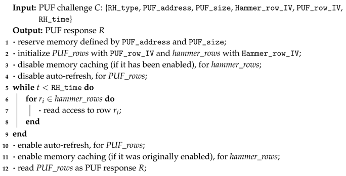
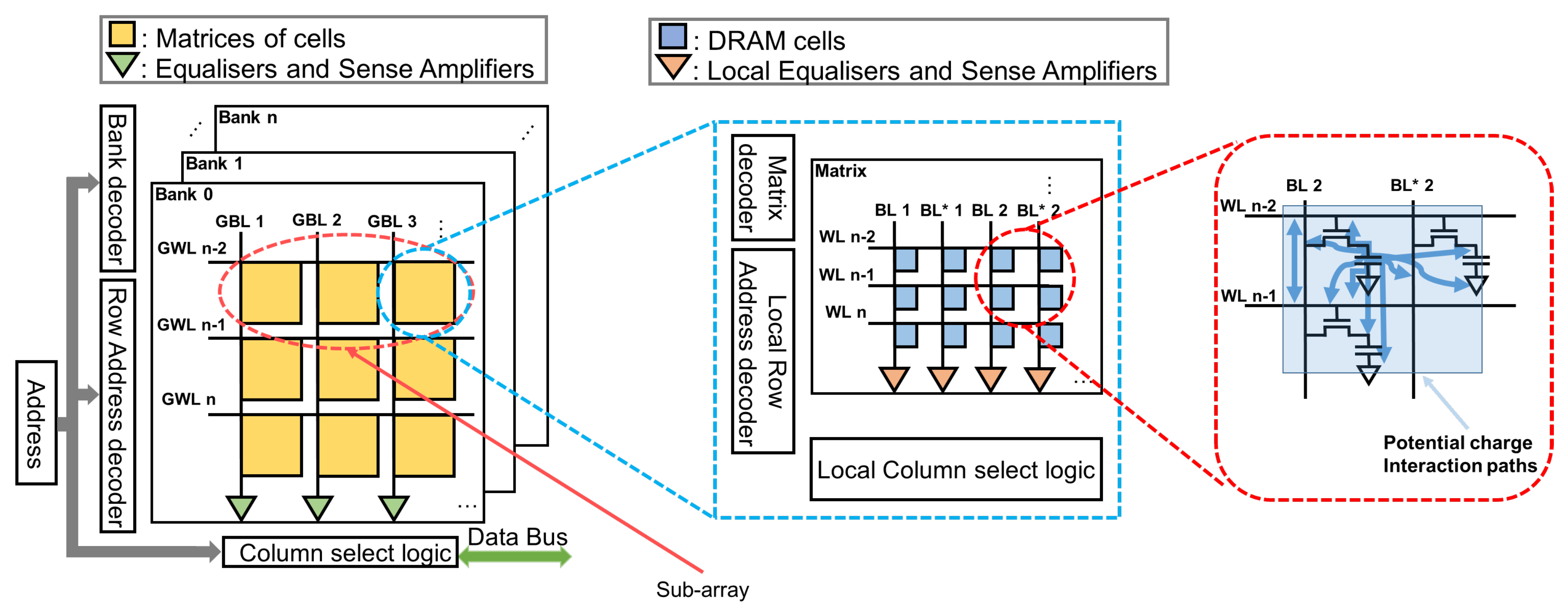
5. Conclusions

This work has presented a flexible firmware implementation of the Row Hammer PUF that was originally introduced by Schaller et al. [1], as well as a run-time accessible implementation of the same PUF. The Row Hammer PUF is a memory-based intrinsic PUF that takes advantage of both the row hammer effect in DRAMs and the data retention characteristic of their cells, in order to provide unique responses. This is the first application of the row hammer effect that can be used to enhance the security of a system, rather than diminish it. Additionally, as DRAM modules are inherent components of most contemporary systems, the Row Hammer PUF can be implemented in them, without the need of additional hardware for its construction or operation.
In this work, we have extensively evaluated both a firmware and a kernel module implementation of the Row Hammer PUF, proving that the two implementations provide equally good results, for all cases assessed. Additionally, we have also confirmed that the Row Hammer PUF can provide unique and robust responses of high entropy. Moreover, we have also shown that, in some cases, disabling the cache can increase the number of bit flips observed in the Row Hammer PUF responses and, therefore, also reduce the time needed to generate a response, or increase its entropy. Finally, we have also demonstrated that the simultaneous use of multiple kernel module implementations of the Row Hammer PUF can also be utilised in order to increase the number of observed bit flips and, therefore, either reduce the time needed to generate responses or increase their entropy.
In general, as we have shown, the Row Hammer PUF can be utilised in order to address the problem of DRAM retention-based PUFs needing extended amounts of time in order to generate their responses [20]. Furthermore, the Row Hammer PUF also provides multiple Challenge–Response Pairs (CRPs) and its kernel module implementation allows access to it at run-time. Moreover, both the firmware and the kernel module implementation of the Row Hammer PUF can be used as a basis for the implementation of cryptographic applications, such as key agreement [17] and authentication [17,18] protocols that have been designed for DRAM retention-based PUFs.
Nevertheless, our extended investigation of the effects of temperature on the Row Hammer PUF has revealed that the Row Hammer PUF is strongly dependent on temperature variations. Temperature variations can significantly affect its robustness and, at extreme cases, even substantially affect its entropy. As this is also a known problem for DRAM retention-based PUFs [17,18,20], we have briefly discussed some potential ways to address this issue. However, as this issue undoubtedly affects the potential of the Row Hammer PUF for commercial adoption and widespread use for practical applications, it needs to be addressed in a much more comprehensive manner by future research. If the dependency of the Row Hammer PUF on temperature can be controlled in an efficient manner, then, this PUF can also potentially be used for the attestation of time and/or temperature. Moreover, future research should additionally investigate and address the effects of voltage variations and aging on the Row Hammer PUF.
Finally, we can conclude that the Row Hammer PUF can, in general, be utilised as a basis for providing flexible, lightweight, cost-efficient and practical run-time cryptographic solutions in low-end COTS devices, such as IoT hardware, that cannot support other more resource-demanding security primitives, such as TPMs. Nevertheless, although the Row Hammer PUF can be used to significantly improve the security of a system, the dependency of all its current implementations on temperature variations must be taken into account, when considering it as a security mechanism.

Author Contributions

N.A.A. has written and proofread most of this paper, has conceived, designed and performed some of the experiments required for it, analysed some of their results and produced some of the figures for this paper. He also helped to write and proofread the original paper [1], of which this paper is an extension. T.A. has encouraged and guided the writing of this paper, by providing crucial insights and feedback that truly helped to improve its quality, has helped with the experiments required for this paper, has produced some of the figures for it and has also proofread it. Y.F. has produced and revised code used for the different implementations of the Row Hammer PUF, has designed and performed most of the experiments required for this paper, has processed most of their results and produced most of the figures for this paper. C.H. has significantly helped to perform the experiments required for this paper, has written a large part of its evaluation section, has provided helpful insights regarding the experiments at different temperatures, has analysed their results and produced some of the figures for this paper. A.S. has conceived the idea for this paper and has provided valuable insights that helped to improve its quality. He also wrote most of the original paper [1], of which this paper is an extension, and produced most of the figures for it. W.X. has encouraged and guided the writing of this paper, by providing useful insights and feedback that helped to improve its quality. She also wrote the background and implementation sections included in the original paper [1], of which this paper is an extension, produced the relevant figures and designed most of the experiments required for that paper. M.J. has produced code used in the kernel module implementation of the Row Hammer PUF, has performed experiments required for this paper and has processed some of their results. M.U.S. has produced code used in the firmware implementation of the Row Hammer PUF and has performed experiments required for this paper. He has also produced code used in the original paper [1], of which this paper is an extension, has performed most of the experiments required for that paper and has processed most of their results. J.L. has performed some of the experiments required for this paper and helped to analyse their results. S.G. has encouraged and guided the writing of this and the original paper [1], of which this paper is an extension, by proofreading them and providing helpful remarks, insights and feedback that helped to improve them. J.S. has guided the writing of this paper and helped to shape it, over helpful discussions on its content and contributions. He also wrote and proofread some of the content included in the original paper [1], of which this paper is an extension. S.K. has guided the writing of this paper, by providing valuable background information, insights and feedback that significantly improved the quality of the paper, especially regarding the way in which the described attacks would work. He also encouraged and guided the writing of the original paper [1], of which this paper is an extension, and provided crucial insights and feedback that truly helped to improve its quality.

Funding

This work has been partly funded by the German Research Foundation (Deutsche ForschungsGemeinschaft— DFG), as part of project P3 within the CRC 1119 CROSSING, and, also, partly by the German Academic Exchange Service (Deutscher Akademischer AustauschDienst–DAAD). This work has also been partly supported and funded by the US National Science Foundation (NSF) under NSF Grant no. 1651945.

Acknowledgments

The authors would like to thank the editors as well as the anonymous reviewers of this work for their constructive comments and remarks that have really helped to improve the quality of this work.

Conflicts of Interest

The authors declare no conflict of interest.

Abbreviations

The following abbreviations are used in this manuscript:
ANOVAANalysis Of Variance
BBytes
CMUCache Management Unit
COTSCommercial Off-The-Shelf
CRPChallenge–Response Pair
DAADGerman Academic Exchange Service (Deutscher Akademischer AustauschDienst)
DFGGerman Research Foundation (Deutsche ForschungsGemeinschaft)
DMADirect Memory Access
DoSDenial of Service
DRAMDynamic Random Access Memory
DSRHDouble-Sided Row Hammering
ECCError Correction Code
FEFuzzy Extractor
GBGigaBytes
IoTInternet of Things
IVInitial Value
KBKiloBytes
LPDDR2Low Power Double Data Rate type 2
MBMegaBytes
MDPIMultidisciplinary Digital Publishing Institute
MPUMicroProcessor Unit
nmnanometer
NSFUS National Science Foundation
OSOperating System
PoPPackage-on-Package
PUFPhysical Unclonable Functions
RHRow Hammering
SDRAMSynchronous Dynamic Random Access Memory
SGX(Intel) Software Guard Extensions
SoCSystem-on-Chip
SSRHSingle-Sided Row Hammering
TLBTranslation Lookaside Buffer
TPMTrusted Platform Module
US/USAUnited States of America

References

  1. Schaller, A.; Xiong, W.; Anagnostopoulos, N.A.; Saleem, M.U.; Gabmeyer, S.; Katzenbeisser, S.; Szefer, J. Intrinsic Rowhammer PUFs: Leveraging the Rowhammer Effect for Improved Security. In Proceedings of the 2017 IEEE International Symposium on Hardware Oriented Security and Trust (HOST), McLean, VA, USA, 1–5 May 2017; pp. 1–7. [Google Scholar] [CrossRef]
  2. Kim, Y.; Daly, R.; Kim, J.; Fallin, C.; Lee, J.H.; Lee, D.; Wilkerson, C.; Lai, K.; Mutlu, O. Flipping Bits in Memory Without Accessing Them: An Experimental Study of DRAM Disturbance Errors. In Proceedings of the 2014 ACM/IEEE 41st International Symposium on Computer Architecture (ISCA), Minneapolis, MN, USA, 14–18 June 2014; pp. 361–372. [Google Scholar] [CrossRef]
  3. Seaborn, M.; Dullien, T. Exploiting the DRAM Rowhammer Bug to Gain Kernel Privileges. Black Hat USA. 2015. Available online: (Presentation Slides) https://www.blackhat.com/docs/us-15/materials/us-15-Seaborn-Exploiting-The-DRAM-Rowhammer-Bug-To-Gain-Kernel-Privileges.pdf (White Paper) https://www.blackhat.com/docs/us-15/materials/us-15-Seaborn-Exploiting-The-DRAM-Rowhammer-Bug-To-Gain-Kernel-Privileges-wp.pdf (accessed on 15 April 2018).
  4. Van der Veen, V.; Fratantonio, Y.; Lindorfer, M.; Gruss, D.; Maurice, C.; Vigna, G.; Bos, H.; Razavi, K.; Giuffrida, C. Drammer: Deterministic Rowhammer Attacks on Mobile Platforms. In Proceedings of the Proceedings of the 2016 ACM SIGSAC Conference on Computer and Communications Security, Vienna, Austria, 24–28 October 2016; ACM: New York, NY, USA, 2016; pp. 1675–1689. [Google Scholar] [CrossRef]
  5. Xiao, Y.; Zhang, X.; Zhang, Y.; Teodorescu, R. One Bit Flips, One Cloud Flops: Cross-VM Row Hammer Attacks and Privilege Escalation. In Proceedings of the 25th USENIX Security Symposium (USENIX Security 16), Austin, TX, USA, 10–12 August 2016; USENIX Association: Austin, TX, USA, 2016; pp. 19–35. [Google Scholar]
  6. Razavi, K.; Gras, B.; Bosman, E.; Preneel, B.; Giuffrida, C.; Bos, H. Flip Feng Shui: Hammering a Needle in the Software Stack. In Proceedings of the 25th USENIX Security Symposium (USENIX Security 16), Austin, TX, USA, 10–12 August 2016; USENIX Association: Austin, TX, USA, 2016; pp. 1–18. [Google Scholar]
  7. Gruss, D.; Maurice, C.; Mangard, S. Rowhammer.js: A Remote Software-Induced Fault Attack in JavaScript. In Detection of Intrusions and Malware, and Vulnerability Assessment; Caballero, J., Zurutuza, U., Rodríguez, R.J., Eds.; Springer International Publishing: Cham, Switzerland, 2016; pp. 300–321. [Google Scholar] [CrossRef]
  8. Aweke, Z.B.; Yitbarek, S.F.; Qiao, R.; Das, R.; Hicks, M.; Oren, Y.; Austin, T. ANVIL: Software-Based Protection Against Next-Generation Rowhammer Attacks. In Proceedings of the Twenty-First International Conference on Architectural Support for Programming Languages and Operating Systems (ASPLOS ’16), Atlanta, GA, USA, 2–6 April 2016; ACM: New York, NY, USA, 2016; pp. 743–755. [Google Scholar] [CrossRef]
  9. Qiao, R.; Seaborn, M. A New Approach for Rowhammer Attacks. In Proceedings of the 2016 IEEE International Symposium on Hardware Oriented Security and Trust (HOST), McLean, VA, USA, 3–5 May 2016; pp. 161–166. [Google Scholar] [CrossRef]
  10. Fainstein, D.; Rosenblatt, S.; Cestero, A.; Robson, N.; Kirihata, T.; Iyer, S.S. Dynamic Intrinsic Chip ID Using 32nm High-K/metal Gate SOI Embedded DRAM. In Proceedings of the 2012 Symposium on VLSI Circuits (VLSIC), Honolulu, HI, USA, 13–15 June 2012; pp. 146–147. [Google Scholar] [CrossRef]
  11. Okamura, T.; Minematsu, K.; Tsunoo, Y.; Iida, T.; Kimura, T.; Nakamura, K. DRAM PUF (In Japanese). In Proceedings of the 29th Symposium on Cryptography and Information Security, Kanazawa, Japan, 1–2 January 2012; Institute of Electronics, Information and Communication Engineers: Tokyo, Japan, 2012. [Google Scholar]
  12. Keller, C.; Felber, N.; Gürkaynak, F.; Kaeslin, H.; Junod, P. Physically Unclonable Functions for Secure Hardware. Swiss National Science Foundation (SNSF), Nano-Tera.CH, RTD 2010—QCrypt. 2012. (Poster) Available online: http://www.nano-tera.ch/pdf/posters2012/QCrypt53.pdf (accessed on 15 April 2018).
  13. Felber, N.; Gisin, N. Secure High-Speed Communication Based on Quantum Key Distribution. Swiss National Science Foundation (SNSF), Nano-Tera.CH, RTD 2010— QCrypt. In Proceedings of the Annual Plenary Meeting, Zurich, Switzerland, 26–27 April 2012; (Presentation Slides) Available online: http://crypto.junod.info/wp-content/uploads/2012/06/qcrypt-slides.pdf (accessed on 15 April 2018).
  14. Anagnostopoulos, N.A.; Katzenbeisser, S.; Chandy, J.; Tehranipoor, F. An Overview of DRAM-Based Security Primitives. Cryptography 2018, 2. [Google Scholar] [CrossRef]
  15. Tehranipoor, F.; Karimian, N.; Xiao, K.; Chandy, J. DRAM Based Intrinsic Physical Unclonable Functions for System Level Security. In Proceedings of the 25th Edition on Great Lakes Symposium on VLSI (GLSVLSI ’15), Pittsburgh, PA, USA, 20–22 May 2015; ACM: New York, NY, USA, 2015; pp. 15–20. [Google Scholar] [CrossRef]
  16. Tehranipoor, F.; Karimian, N.; Yan, W.; Chandy, J.A. DRAM-Based Intrinsic Physically Unclonable Functions for System-Level Security and Authentication. IEEE Trans. Large Scale Integr. (VLSI) Syst. 2017, 25, 1085–1097. [Google Scholar] [CrossRef]
  17. Xiong, W.; Schaller, A.; Anagnostopoulos, N.A.; Saleem, M.U.; Gabmeyer, S.; Katzenbeisser, S.; Szefer, J. Run-Time Accessible DRAM PUFs in Commodity Devices. In Cryptographic Hardware and Embedded Systems—CHES 2016; Gierlichs, B., Poschmann, A.Y., Eds.; Springer: Berlin/Heidelberg, Germany, 2016; pp. 432–453. [Google Scholar]
  18. Schaller, A.; Xiong, W.; Anagnostopoulos, N.A.; Saleem, M.U.; Gabmeyer, S.; Skoric, B.; Katzenbeisser, S.; Szefer, J. Decay-Based DRAM PUFs in Commodity Devices. IEEE Trans. Dependable Secure Comput. 2018. [Google Scholar] [CrossRef]
  19. Hashemian, M.S.; Singh, B.; Wolff, F.; Weyer, D.; Clay, S.; Papachristou, C. A Robust Authentication Methodology Using Physically Unclonable Functions in DRAM Arrays. In Proceedings of the 2015 Design, Automation Test in Europe Conference Exhibition (DATE), Grenoble, France, 9–13 March 2015; pp. 647–652. [Google Scholar] [CrossRef]
  20. Kim, J.S.; Patel, M.; Hassan, H.; Mutlu, O. The DRAM Latency PUF: Quickly Evaluating Physical Unclonable Functions by Exploiting the Latency-Reliability Tradeoff in Modern Commodity DRAM Devices. In Proceedings of the 2018 IEEE International Symposium on High Performance Computer Architecture (HPCA), Vienna, Austria, 24–28 February 2018; pp. 194–207. [Google Scholar] [CrossRef]
  21. Liu, J.; Jaiyen, B.; Kim, Y.; Wilkerson, C.; Mutlu, O. An Experimental Study of Data Retention Behavior in Modern DRAM Devices: Implications for Retention Time Profiling Mechanisms. In Proceedings of the 40th Annual International Symposium on Computer Architecture, Tel-Aviv, Israel, 23–27 June 2013; ACM: New York, NY, USA, 2013; pp. 60–71. [Google Scholar] [CrossRef]
  22. Kim, Y.; Seshadri, V.; Lee, D.; Liu, J.; Mutlu, O. A Case for Exploiting Subarray-Level Parallelism (SALP) in DRAM. In Proceedings of the 2012 39th Annual International Symposium on Computer Architecture (ISCA), Portland, OR, USA, 9–13 June 2012; pp. 368–379. [Google Scholar] [CrossRef]
  23. Zhang, T.; Chen, K.; Xu, C.; Sun, G.; Wang, T.; Xie, Y. Half-DRAM: A high-bandwidth and low-power DRAM architecture from the rethinking of fine-grained activation. In Proceedings of the 2014 ACM/IEEE 41st International Symposium on Computer Architecture (ISCA), Minneapolis, MN, USA, 14–18 June 2014; pp. 349–360. [Google Scholar] [CrossRef]
  24. Bhati, I.; Chishti, Z.; Lu, S.L.; Jacob, B. Flexible Auto-Refresh: Enabling Scalable and Energy-Efficient DRAM Refresh Reductions. In Proceedings of the 2015 ACM/IEEE 42nd Annual International Symposium on Computer Architecture (ISCA), Portland, OR, USA, 13–17 June 2015; pp. 235–246. [Google Scholar] [CrossRef]
  25. Micheletti, M.; LeCroy, T. Tuning DDR4 for Power and Performance. MemCon 2013. Available online: http://www.memcon.com/pdfs/proceedings2013/track1/Tuning_DDR4_for_Power_and_Performance.pdf (accessed on 15 April 2018).
  26. Mutlu, O. The RowHammer Problem and Other Issues We May Face as Memory Becomes Denser. In Proceedings of the Design, Automation Test in Europe Conference Exhibition (DATE), Lausanne, Switzerland, 27–31 March 2017; pp. 1116–1121. [Google Scholar] [CrossRef]
  27. Chia, P.C.F.; Wen, S.J.; Baeg, S.H. New DRAM HCI Qualification Method Emphasizing on Repeated Memory Access. In Proceedings of the 2010 IEEE International Integrated Reliability Workshop Final Report, Fallen Leaf, CA, USA, 17–21 October 2010; pp. 142–144. [Google Scholar] [CrossRef]
  28. Baeg, S.; Chia, P.; Wen, S.; Wong, R. DRAM Failure Cases Under Hot-Carrier Injection. In Proceedings of the 18th IEEE International Symposium on the Physical and Failure Analysis of Integrated Circuits (IPFA), Incheon, South Korea, 4–7 July 2011; pp. 1–3. [Google Scholar] [CrossRef]
  29. Bidokhti, N.; Tehranipoor, M.; Chen, J.; Lee, J. Life After Failure. In Proceedings of the 2014 Reliability and Maintainability Symposium, Colorado Springs, CO, USA, 27–30 January 2014; pp. 1–7. [Google Scholar] [CrossRef]
  30. Jung, M.; Rheinländer, C.C.; Weis, C.; Wehn, N. Reverse Engineering of DRAMs: Row Hammer with Crosshair. In Proceedings of the Second International Symposium on Memory Systems; ACM: New York, NY, USA, 2016; pp. 471–476. [Google Scholar] [CrossRef]
  31. Bhattacharya, S.; Mukhopadhyay, D. Curious Case of Rowhammer: Flipping Secret Exponent Bits Using Timing Analysis. In Cryptographic Hardware and Embedded Systems—CHES 2016; Gierlichs, B., Poschmann, A.Y., Eds.; Springer: Berlin/Heidelberg, Germany, 2016; pp. 602–624. [Google Scholar] [CrossRef]
  32. Bhattacharya, S.; Mukhopadhyay, D. Advanced Fault Attacks in Software: Exploiting the Rowhammer Bug. In Fault Tolerant Architectures for Cryptography and Hardware Security; Patranabis, S., Mukhopadhyay, D., Eds.; Springer: Singapore, 2018; pp. 111–135. [Google Scholar] [CrossRef]
  33. Jang, Y.; Lee, J.; Lee, S.; Kim, T. SGX-Bomb: Locking Down the Processor via Rowhammer Attack. In Proceedings of the 2nd Workshop on System Software for Trusted Execution, Shanghai, China, 28 October 2017; ACM: New York, NY, USA, 2017. [Google Scholar] [CrossRef]
  34. Yan, W.; Tehranipoor, F.; Chandy, J.A. A Novel Way to Authenticate Untrusted Integrated Circuits. In Proceedings of the 2015 IEEE/ACM International Conference on Computer-Aided Design (ICCAD), Austin, TX, USA, 2–6 November 2015; pp. 132–138. [Google Scholar] [CrossRef]
  35. Yan, W.; Tehranipoor, F.; Chandy, J.A. PUF-Based Fuzzy Authentication Without Error Correcting Codes. IEEE Trans. Comput.-Aided Design Integr. Circuits Syst. 2017, 36, 1445–1457. [Google Scholar] [CrossRef]
  36. Maes, R.; Tuyls, P.; Verbauwhede, I. A Soft Decision Helper Data Algorithm for SRAM PUFs. In Proceedings of the 2009 IEEE International Symposium on Information Theory, Seoul, Korea, 28 June–3 July 2009; pp. 2101–2105. [Google Scholar] [CrossRef]
  37. Guajardo, J.; Kumar, S.S.; Schrijen, G.J.; Tuyls, P. FPGA Intrinsic PUFs and Their Use for IP Protection. In Cryptographic Hardware and Embedded Systems—CHES 2007; Paillier, P., Verbauwhede, I., Eds.; Springer: Berlin/Heidelberg, Germany, 2007; pp. 63–80. [Google Scholar] [CrossRef]
  38. Holcomb, D.E.; Burleson, W.P.; Fu, K. Initial SRAM State as a Fingerprint and Source of True Random Numbers for RFID Tags. In Proceedings of the Conference on RFID Security, 2007; Available online: http://www.rfidsec07.etsit.uma.es/slides/papers/paper-12.pdf (accessed on 15 April 2018).
  39. Prabhu, P.; Akel, A.; Grupp, L.M.; Yu, W.K.S.; Suh, G.E.; Kan, E.; Swanson, S. Extracting Device Fingerprints from Flash Memory by Exploiting Physical Variations. In Trust and Trustworthy Computing; McCune, J.M., Balacheff, B., Perrig, A., Sadeghi, A.R., Sasse, A., Beres, Y., Eds.; Springer: Berlin, Heidelberg, 2011; pp. 188–201. [Google Scholar] [CrossRef]
  40. Herder, C.; Yu, M.D.; Koushanfar, F.; Devadas, S. Physical Unclonable Functions and Applications: A Tutorial. Proc. IEEE 2014, 102, 1126–1141. [Google Scholar] [CrossRef]
  41. Yan, W.; Jin, C.; Tehranipoor, F.; Chandy, J.A. Phase Calibrated Ring Oscillator PUF Design and Implementation on FPGAs. In Proceedings of the 2017 27th International Conference on Field Programmable Logic and Applications (FPL), Ghent, Belgium, 4–8 September 2017; pp. 1–8. [Google Scholar] [CrossRef]
  42. Schrijen, G.J.; van der Leest, V. Comparative Analysis of SRAM Memories Used as PUF Primitives. In Proceedings of the 2012 Design, Automation Test in Europe Conference Exhibition (DATE), Dresden, Germany, 12–16 March 2012; pp. 1319–1324. [Google Scholar] [CrossRef]
  43. Katzenbeisser, S.; Kocabaş, Ü.; Rožić, V.; Sadeghi, A.R.; Verbauwhede, I.; Wachsmann, C. PUFs: Myth, Fact or Busted? A Security Evaluation of Physically Unclonable Functions (PUFs) Cast in Silicon. In Cryptographic Hardware and Embedded Systems—CHES 2012; Prouff, E., Schaumont, P., Eds.; Springer: Berlin/Heidelberg, Germany, 2012; pp. 283–301. [Google Scholar] [CrossRef]
  44. Hamamoto, T.; Sugiura, S.; Sawada, S. On the Retention Time Distribution of Dynamic Random Access Memory (DRAM). IEEE Trans. Electron Devices 1998, 45, 1300–1309. [Google Scholar] [CrossRef]
  45. Aichinger, B. DDR Memory Errors Caused by Row Hammer. In Proceedings of the 2015 IEEE High Performance Extreme Computing Conference (HPEC), Waltham, MA, USA, 15–17 September 2015; pp. 1–5. [Google Scholar] [CrossRef]
  46. PandaBoard. OMAPpedia.org Wiki. Available online: http://omappedia.org/wiki/PandaBoard (accessed on 15 April 2018).
  47. OMAP4460 Pandaboard ES System Reference Manual. PandaBoard.org, 29 September 2011. Revision 0.1, DOC-21054. Available online: https://www.cs.utexas.edu/~simon/378/resources/PandaBoardES.pdf (accessed on 15 April 2018).
  48. OMAP4460 Multimedia Device Technical Reference Manual. Texas Instruments Incorporated, February 2011–Revised April 2014. Silicon Revision 1.x, Version AB. Available online: http://www.ti.com/lit/ug/swpu235ab/swpu235ab.pdf (accessed on 15 April 2018).
  49. 8 G bits DDR2 Mobile RAM PoP (12mm × 12mm, 216-ball FBGA) EDB8164B3PF. Micron Technology, Inc., Formerly Elpida Memory, Inc. Available online: https://www.micron.com/parts/dram/mobile-ddr2-sdram/edb8164b3pf-8d-f (accessed on 15 April 2018).
  50. Das U-Boot—The Universal Boot Loader. DENX Software Engineering. Available online: http://www.denx.de/wiki/U-Boot/WebHome (accessed on 15 April 2018).
  51. Kraft, K.; Sudarshan, C.; Mathew, D.M.; Weis, C.; Wehn, N.; Jung, M. Improving the error behavior of DRAM by exploiting its Z-channel property. In Proceedings of the 2018 Design, Automation Test in Europe Conference Exhibition (DATE), Dresden, Germany, 19–23 March 2018; pp. 1492–1495. [Google Scholar] [CrossRef]
  52. Jaccard, P. Étude Comparative de la Distribution Florale dans une Portion des Alpes et du Jura. In Bulletin de la Societe Vaudoise des Sciences Naturelles; F. Rouge & Cie S.A.: Lausanne, Switzerland, 1901; Volume 37, pp. 547–579. [Google Scholar] [CrossRef]
  53. Dodis, Y.; Reyzin, L.; Smith, A. Fuzzy Extractors: How to Generate Strong Keys from Biometrics and Other Noisy Data. In Advances in Cryptology—EUROCRYPT 2004; Cachin, C., Camenisch, J.L., Eds.; Springer: Berlin/Heidelberg, Germany, 2004; pp. 523–540. [Google Scholar] [CrossRef]
  54. Rahmati, A.; Hicks, M.; Holcomb, D.E.; Fu, K. Probable Cause: The Deanonymizing Effects of Approximate DRAM. In Proceedings of the 42nd Annual International Symposium on Computer Architecture, Portland, OR, USA, 13–17 June 2015; ACM: New York, NY, USA, 2015; pp. 604–615. [Google Scholar] [CrossRef]
  55. Bakeman, R. Recommended Effect Size Statistics for Repeated Measures Designs. Behav. Res. Methods 2005, 37, 379–384. [Google Scholar] [CrossRef] [PubMed]
  56. Halderman, J.A.; Schoen, S.D.; Heninger, N.; Clarkson, W.; Paul, W.; Calandrino, J.A.; Feldman, A.J.; Appelbaum, J.; Felten, E.W. Lest We Remember: Cold-boot Attacks on Encryption Keys. Commun. ACM 2009, 52, 91–98. [Google Scholar] [CrossRef]
  57. Anagnostopoulos, N.A. Optical Fault Injection Attacks in Smart Card Chips and an Evaluation of Countermeasures against Them. Master’s Thesis, University of Twente, Enschede, The Netherlands, 2014. [Google Scholar]
Figure 1. Schematics of the organisation of the DRAM module. The blue arrows show potential leakage paths. (Figure adapted from a figure of the original paper by Schaller et al. [1].)
Cryptography 02 00013 g001
Figure 2. Row Hammering types: (a) Double-Sided Row Hammering (DSRH) with PUF size = 12 KB; (b) Single-Sided Row Hammering (SSRH) with PUF size = 16 KB. We assume that the row size of the DRAM bank used is 4 KB. (Figure from the original paper by Schaller et al. [1].)
Cryptography 02 00013 g002
Figure 3. Average fractional number of bit flips observed in the responses of the original Row Hammer PUF, given in percentages relative to PUF size, depending on combinations of hammer row IV and PUF row IV. Configuration used: PUF size = 128 KB and RH time = 120 s and (RH type = SSRH/RH type = DSRH).
Cryptography 02 00013 g003
Figure 4. Average fractional number of bit flips observed in the responses of the original Row Hammer PUF, given in percentages relative to PUF size, using PUF row IV = ‘0xAA’, different values of hammer row IV and, (a) RH type = SSRH or (b) RH type = DSRH. (Figure from the original paper by Schaller et al. [1].)
Cryptography 02 00013 g004
Figure 5. Histogram of J i n t e r and J i n t r a values for the original three PUF instances using 20 measurements with PUF row IV = ‘0xAA’, hammer row IV = ‘0x55’, PUF size = 128 KB and RH type = SSRH. (Figure from the original paper by Schaller et al. [1].)
Cryptography 02 00013 g005
Figure 6. Average fractional number of bit flips observed in the responses of the firmware implementation of the Row Hammer PUF, given in percentages relative to PUF size, depending on combinations of hammer row IV and PUF row IV. Configuration used: PUF size = 128 KB, (RH time = 60 s/RH time = 120 s), (RH type = SSRH/RH type = DSRH) and (Cache disabled/Cache enabled).
Cryptography 02 00013 g006
Figure 7. Average fractional number of bit flips observed in the responses of the kernel module implementation of the Row Hammer PUF, given in percentages relative to PUF size, depending on combinations of hammer row IV and PUF row IV. Configuration used: PUF size = 128 KB, (RH time = 60 s/RH time = 120 s), (RH type = SSRH/RH type = DSRH) and (Cache disabled/Cache enabled).
Cryptography 02 00013 g007
Figure 8. Histogram of J i n t e r and J i n t r a values for the firmware and kernel module implementations, using 20 measurements for each case of different combinations of RH type, PUF row IV, hammer row IV, Cache state and (RH time = 60 s/RH time = 120 s), for PUF size = 128 KB, according to Table 3.
Cryptography 02 00013 g008
Figure 9. Histogram of J i n t e r and J i n t r a values for the firmware implementation, using 20 measurements for each case of different combinations of RH type, PUF row IV, hammer row IV, Cache state and RH time, for PUF size = 128 KB, according to Table 3.
Cryptography 02 00013 g009
Figure 10. Histogram of J i n t e r and J i n t r a values for the kernel module implementation, using 20 measurements for each case of different combinations of RH type, PUF row IV, hammer row IV, Cache state and RH time, for PUF size = 128 KB, according to Table 3.
Cryptography 02 00013 g010
Figure 11. Distributions of J i n t e r values, grouped by hammer row IV, for different PUF row IV, Cache states and RH type, for the firmware implementation. J i n t e r values for RH time = 60 s and RH time = 120 s are grouped in a single distribution, per case.
Cryptography 02 00013 g011
Figure 12. Distributions of J i n t e r values, grouped by hammer row IV, for different PUF row IV, Cache states and RH type, for the kernel module implementation. J i n t e r values for RH time = 60 s and RH time = 120 s are grouped in a single distribution, per case.
Cryptography 02 00013 g012
Figure 13. Distributions of J i n t r a values, grouped by hammer row IV, for different PUF row IV, Cache states and RH type, for the firmware implementation. J i n t r a values for RH time = 60 s and RH time = 120 s are grouped in a single distribution, per case.
Cryptography 02 00013 g013
Figure 14. Distributions of J i n t r a values, grouped by hammer row IV, for different PUF row IV, Cache states and RH type, for the kernel module implementation. J i n t r a values for RH time = 60 s and RH time = 120 s are grouped in a single distribution, per case.
Cryptography 02 00013 g014
Figure 15. Temperature dependency of the average fractional number of bit flips observed in the responses of the firmware implementation, given in percentages relative to PUF size, for PUF size = 128 KB, RH type = DSRH), PUF row IV = 0xAA, hammer row IV = 0x55, with the Cache disabled, (RH time = 60 s/RH time = 120 s) and ambient temperatures between 0 C to 70 C. 20 measurements have been performed for each combination of the presented values of the PUF parameters.
Cryptography 02 00013 g015
Figure 16. Temperature dependency of the average fractional number of bit flips observed in the responses of the kernel module implementation, given in percentages relative to PUF size, for PUF size = 128 KB, RH type = DSRH), PUF row IV = 0xAA, hammer row IV = 0x55, with the Cache disabled, (RH time = 60 s/RH time = 120 s) and ambient temperatures between 0 C to 70 C. 20 measurements have been performed for each combination of the presented values of the PUF parameters.
Cryptography 02 00013 g016
Figure 17. Temperature dependency of the J i n t e r and J i n t r a values for the responses of the firmware implementation, for PUF size = 128 KB, RH type = DSRH), PUF row IV = 0xAA, hammer row IV = 0x55, with the Cache disabled, (RH time = 60 s/RH time = 120 s) and ambient temperatures between 0 C to 70 C. 20 measurements have been performed for each combination of the presented values of the PUF parameters.
Cryptography 02 00013 g017
Figure 18. Temperature dependency of the J i n t e r and J i n t r a values for the responses of the kernel module implementation, for PUF size = 128 KB, RH type = DSRH), PUF row IV = 0xAA, hammer row IV = 0x55, with the Cache disabled, (RH time = 60 s/RH time = 120 s) and ambient temperatures between 0 C to 70 C. 20 measurements have been performed for each combination of the presented values of the PUF parameters.
Cryptography 02 00013 g018
Figure 19. J i n t r a values for pairs of PUF responses taken at the same or different temperatures from each other. J i n t r a values for the firmware and the kernel module implementations have been grouped together, for each case presented. J i n t r a values for RH time = 60 s and for RH time = 120 s have also been grouped together, for each case presented. Configuration used: PUF size = 128 KB, RH type = DSRH), PUF row IV = 0xAA, hammer row IV = 0x55, with the Cache disabled.
Cryptography 02 00013 g019
Figure 20. Average fractional number of bit flips observed in the responses of the Row Hammer PUF, when only one kernel module implementation is running and when two kernel module implementations are running simultaneously, given in percentages relative to PUF size, depending on combinations of hammer row IV and PUF row IV. Configuration used: PUF size = 128 KB, Cache disabled, RH type = DSRH and (RH time = 60 s/RH time = 120 s).
Cryptography 02 00013 g020
Figure 21. Histogram of J i n t e r and J i n t r a values for responses of the Row Hammer PUF, when two kernel module implementations are running simultaneously, using 20 measurements for each case of different combinations of PUF row IV, hammer row IV, RH type = DSRH, Cache disabled and (RH time = 60 s/RH time = 120 s), for PUF size = 128 KB.
Cryptography 02 00013 g021
Table 1. Parameters used for the evaluation of the original Row Hammer PUF characteristics, and their corresponding sets of values. Additionally, this firmware implementation is executed before caching is enabled. (Table from the original paper by Schaller et al. [1].)
ParameterEvaluated Values
RH typesingle-sided (SSRH), double-sided (DSRH)
PUF size4 KB, 32 KB, 128 KB
hammer row IV0x00’, ‘0x55’, ‘0xAA’, ‘0xFF
PUF row IV0x00’, ‘0x55’, ‘0xAA’, ‘0xFF
RH time60 s, 120 s
Cache(implicitly) disabled
Table 2. Overview of the average number of bit flips observed in the responses of the original Row Hammer PUF, depending on combinations of hammer row IV and PUF row IV. Configuration used: PUF size = 128 KB and RH time = 120 s and (RH type = SSRH/RH type = DSRH). (Table from the original paper by Schaller et al. [1].)
PUF Row IVHammer Row IV
0x000x550xAA0xFF
0x007405/803217558/203587391/720017288/20152
0x550/00/00/00/0
0xAA22547/24480 32904 / 37548 14218/1424324479/28268
0xFF15633/1779815402/175796132/64796095/6416
Table 3. Parameters used for evaluation of the Row Hammer PUF characteristics, and their corresponding set of values. Compared to Table 1, the PUF size is fixed to 128 KB and caching can be enabled or disabled through the manipulation of the registers of the Cache Management Unit (CMU). Additionally, cases with PUF row IV = ‘0x55’ are not examined in depth, as we have verified that they lead to no bit flips for our PandaBoard implementations. Finally, both the firmware and the kernel module implementation have been tested using this configuration.
ParameterEvaluated Values
RH typesingle-sided (SSRH), double-sided (DSRH)
PUF size128 KB
PUF row IV0x00’, ‘0xAA’, ‘0xFF
hammer row IV0x00’, ‘0x55’, ‘0xAA’, ‘0xFF
RH time60 s, 120 s
Cacheenabled, disabled
Table 4. Average number of bit flips and minimum J i n t r a values obtained at operating temperatures of 40 C, 50 C and 60 C, for the original Row Hammer PUF implementation with PUF row IV = ‘0xAA’, hammer row IV = ‘0x55’, PUF size = 128 KB, RH time = 120 s and RH type = SSRH. (Table from the original paper by Schaller et al. [1].)
MetricOperational Temperature
40 °C50 °C60 °C
avg. bit flips3290465431132450
min. J i n t r a 0.96620.98100.9847
Table 5. 3 × 3 windows showing the average probability of the neighbouring PUF row cells of a PUF row cell that has flipped to have a logical value of one, at room temperature for the firmware implementation, when PUF size = 128 KB, RH time = 120 s, hammer row IV = ‘0x55’ and PUF row IV = ‘0xAA’ and (a) caching is disabled and RH type = DSRH; (b) caching is enabled and RH type = DSRH; (c) caching is disabled and RH type = SSRH; and (d) caching is enabled and RH type = SSRH. Note that the cells in the 3 × 3 windows presented are adjacent to each other in the DRAM module only if they are in the same row of each window.
(a)(b)
0.5353 0.4712 0.5359 0.5360 0.4703 0.5366
0.5359 f l i p 0.5346 0.5363 f l i p 0.5353
0.5342 0.4710 0.5349 0.5347 0.4701 0.5354
(c)(d)
0.5306 0.4736 0.5303 0.5305 0.4738 0.5299
0.5322 f l i p 0.5301 0.5320 f l i p 0.5298
0.5322 0.4736 0.5315 0.5321 0.4738 0.5312
Table 6. 3 × 3 windows showing the average probability of the neighbouring PUF row cells of a PUF row cell that has flipped to have a logical value of one, at room temperature for the kernel module implementation, when PUF size = 128 KB, RH time = 120 s, hammer row IV = ‘0x55’ and PUF row IV = ‘0xAA’ and (a) caching is disabled and RH type = DSRH; (b) caching is enabled and RH type = DSRH; (c) caching is disabled and RH type = SSRH; and (d) caching is enabled and RH type = SSRH. Note that the cells in the 3 × 3 windows presented are adjacent to each other in the DRAM module only if they are in the same row of each window.
(a)(b)
0.5166 0.4874 0.5155 0.5190 0.4849 0.5177
0.5158 f l i p 0.5154 0.5186 f l i p 0.5172
0.5157 0.4871 0.5147 0.5180 0.4845 0.5168
(c)(d)
0.5146 0.4867 0.5148 0.5162 0.4859 0.5154
0.5155 f l i p 0.5149 0.5169 f l i p 0.5154
0.5159 0.4865 0.5160 0.5170 0.4858 0.5161
Table 7. 7 × 7 windows showing the average probability of the neighbouring PUF row cells of a PUF row cell that has flipped, to have also flipped, at room temperature for the firmware implementation, when PUF size = 128 KB, RH time = 120 s, hammer row IV = ‘0x55’ and PUF row IV = ‘0xAA’ and (a) caching is disabled and RH type = DSRH; (b) caching is enabled and RH type = DSRH; (c) caching is disabled and RH type = SSRH; and (d) caching is enabled and RH type = SSRH. Note that the cells in the 7 × 7 windows presented are adjacent to each other in the DRAM module only if they are in the same row of each window.
(a)(b)
0.0441 0.0433 0.0440 0.0456 0.0441 0.0442 0.0440 0.0427 0.0420 0.0427 0.0441 0.0427 0.0428 0.0428
0.0446 0.0440 0.0427 0.0450 0.0440 0.0441 0.0445 0.0431 0.0425 0.0413 0.0437 0.0426 0.0426 0.0430
0.0438 0.0441 0.0441 0.0457 0.0435 0.0440 0.0435 0.0425 0.0424 0.0426 0.0445 0.0420 0.0426 0.0422
0.0446 0.0482 0.0458 f l i p 0.0458 0.0482 0.0446 0.0433 0.0465 0.0442 f l i p 0.0442 0.0465 0.0433
0.0435 0.0442 0.0436 0.0457 0.0442 0.0443 0.0439 0.0422 0.0429 0.0422 0.0445 0.0427 0.0426 0.0426
0.0445 0.0441 0.0440 0.0451 0.0430 0.0439 0.0447 0.0431 0.0426 0.0426 0.0438 0.0416 0.0426 0.0432
0.0449 0.0457 0.0453 0.0461 0.0449 0.0446 0.0452 0.0437 0.0443 0.0438 0.0447 0.0436 0.0434 0.0437
(c)(d)
0.0338 0.0349 0.0342 0.0353 0.0340 0.0342 0.0339 0.0335 0.0348 0.0340 0.0351 0.0338 0.0342 0.0337
0.0240 0.0239 0.0230 0.0240 0.0237 0.0226 0.0232 0.0238 0.0237 0.0229 0.0238 0.0236 0.0224 0.0230
0.0329 0.0323 0.0325 0.0341 0.0333 0.0339 0.0329 0.0328 0.0322 0.0323 0.0338 0.0331 0.0337 0.0327
0.0468 0.0488 0.0460 f l i p 0.0460 0.0488 0.0468 0.0466 0.0486 0.0459 f l i p 0.0459 0.0486 0.0466
0.0356 0.0366 0.0359 0.0369 0.0353 0.0347 0.0354 0.0354 0.0363 0.0358 0.0366 0.0350 0.0346 0.0353
0.0234 0.0228 0.0237 0.0242 0.0234 0.0239 0.0241 0.0232 0.0226 0.0236 0.0240 0.0233 0.0237 0.0240
0.0323 0.0326 0.0323 0.0343 0.0321 0.0335 0.0323 0.0321 0.0325 0.0321 0.0341 0.0319 0.0335 0.0319
Table 8. 7 × 7 windows showing the average probability of the neighbouring PUF row cells of a PUF row cell that has flipped, to have also flipped, at room temperature for the kernel module implementation, when PUF size = 128 KB, RH time = 120 s, hammer row IV = ‘0x55’ and PUF row IV = ‘0xAA’ and (a) caching is disabled and RH type = DSRH; (b) caching is enabled and RH type = DSRH; (c) caching is disabled and RH type = SSRH; and (d) caching is enabled and RH type = SSRH. Note that the cells in the 7 × 7 windows presented are adjacent to each other in the DRAM module only if they are in the same row of each window.
(a)(b)
0.0339 0.0344 0.0337 0.0344 0.0350 0.0347 0.0339 0.0303 0.0308 0.0304 0.0312 0.0316 0.0311 0.0305
0.0344 0.0337 0.0341 0.0357 0.0347 0.0341 0.0343 0.0309 0.0302 0.0303 0.0320 0.0308 0.0309 0.0308
0.0348 0.0346 0.0345 0.0362 0.0345 0.0339 0.0341 0.0312 0.0312 0.0308 0.0327 0.0315 0.0304 0.0303
0.0339 0.0363 0.0343 f l i p 0.0343 0.0363 0.0339 0.0302 0.0327 0.0303 f l i p 0.0303 0.0327 0.0302
0.0341 0.0343 0.0345 0.0361 0.0347 0.0347 0.0347 0.0303 0.0308 0.0314 0.0326 0.0311 0.0313 0.0311
0.0342 0.0341 0.0346 0.0355 0.0341 0.0339 0.0344 0.0307 0.0308 0.0309 0.0317 0.0301 0.0303 0.0308
0.0336 0.0349 0.0351 0.0343 0.0340 0.0348 0.0342 0.0300 0.0312 0.0316 0.0310 0.0308 0.0310 0.0305
(c)(d)
0.0351 0.0349 0.0353 0.0377 0.0356 0.0361 0.0357 0.0279 0.0275 0.0275 0.0295 0.0282 0.0280 0.0276
0.0366 0.0361 0.0377 0.0369 0.0362 0.0363 0.0378 0.0288 0.0287 0.0296 0.0288 0.0289 0.0286 0.0298
0.0360 0.0372 0.0358 0.0375 0.0366 0.0366 0.0370 0.0280 0.0294 0.0284 0.0293 0.0289 0.0294 0.0295
0.0366 0.0381 0.0376 f l i p 0.0376 0.0381 0.0366 0.0287 0.0301 0.0295 f l i p 0.0295 0.0301 0.0287
0.0370 0.0371 0.0367 0.0379 0.0361 0.0373 0.0361 0.0295 0.0297 0.0290 0.0298 0.0286 0.0295 0.0281
0.0374 0.0363 0.0365 0.0372 0.0378 0.0364 0.0369 0.0294 0.0287 0.0291 0.0293 0.0298 0.0292 0.0293
0.0368 0.0372 0.0367 0.0386 0.0360 0.0360 0.0367 0.0285 0.0290 0.0290 0.0305 0.0283 0.0284 0.0293
Table 9. 7 × 7 windows showing the average probability of the neighbouring PUF row cells of a PUF row cell that has flipped at RH time = 120 s, to have flipped RH time = 60 s, at room temperature for the firmware implementation, when PUF size = 128 KB, hammer row IV = ‘0x55’ and PUF row IV = ‘0xAA’ and (a) caching is disabled and RH type = DSRH; (b) caching is enabled and RH type = DSRH; (c) caching is disabled and RH type = SSRH; and (d) caching is enabled and RH type = SSRH. Note that the cells in the 7 × 7 windows presented are adjacent to each other in the DRAM module only if they are in the same row of each window.
(a)(b)
0.0096 0.0099 0.0094 0.0105 0.0100 0.0099 0.0098 0.0092 0.0095 0.0091 0.0100 0.0096 0.0096 0.0095
0.0103 0.0099 0.0093 0.0106 0.0102 0.0100 0.0097 0.0099 0.0096 0.0089 0.0103 0.0098 0.0096 0.0093
0.0100 0.0098 0.0101 0.0104 0.0099 0.0100 0.0101 0.0098 0.0094 0.0097 0.0100 0.0095 0.0096 0.0096
0.0104 0.0110 0.0107 f l i p 0.0109 0.0109 0.0100 0.0100 0.0105 0.0103 f l i p 0.0105 0.0105 0.0097
0.0099 0.0100 0.0099 0.0107 0.0097 0.0101 0.0100 0.0096 0.0096 0.0095 0.0103 0.0093 0.0097 0.0096
0.0103 0.0100 0.0100 0.0110 0.0099 0.0102 0.0100 0.0099 0.0097 0.0096 0.0107 0.0095 0.0097 0.0095
0.0104 0.0105 0.0105 0.0109 0.0102 0.0109 0.0104 0.0101 0.0103 0.0101 0.0106 0.0099 0.0105 0.0099
(c)(d)
0.0084 0.0081 0.0080 0.0089 0.0088 0.0087 0.0088 0.0083 0.0081 0.0079 0.0089 0.0087 0.0087 0.0088
0.0054 0.055 0.0054 0.0060 0.0056 0.0055 0.0058 0.0054 0.0054 0.0053 0.0060 0.0054 0.0055 0.0058
0.0089 0.0088 0.0090 0.0091 0.0086 0.0089 0.0086 0.0090 0.0087 0.0089 0.0091 0.0086 0.0088 0.0086
0.0125 0.0132 0.0125 f l i p 0.0124 0.0135 0.0125 0.0125 0.0131 0.0124 f l i p 0.0123 0.0135 0.0124
0.0090 0.0094 0.0091 0.0092 0.0088 0.0088 0.0088 0.0089 0.0093 0.0091 0.0091 0.0088 0.0088 0.0087
0.0054 0.0055 0.0052 0.0061 0.0050 0.0056 0.0058 0.0053 0.0054 0.0051 0.0059 0.0050 0.0055 0.0057
0.0079 0.0087 0.0082 0.0089 0.0082 0.0086 0.0080 0.0078 0.0087 0.0082 0.0088 0.0081 0.0086 0.0079
Table 10. 7 × 7 windows showing the average probability of the neighbouring PUF row cells of a PUF row cell that has flipped at RH time = 120 s, to have flipped RH time = 60 s, at room temperature for the kernel module implementation, when PUF size = 128 KB, hammer row IV = ‘0x55’ and PUF row IV = ‘0xAA’ and (a) caching is disabled and RH type = DSRH; (b) caching is enabled and RH type = DSRH; (c) caching is disabled and RH type = SSRH; and (d) caching is enabled and RH type = SSRH. Note that the cells in the 3 × 3 windows presented are adjacent to each other in the DRAM module only if they are in the same row of each window.
(a)(b)
0.0091 0.0094 0.0088 0.0093 0.0095 0.0095 0.0092 0.0076 0.0079 0.0075 0.0077 0.0081 0.0081 0.0079
0.0094 0.0092 0.0093 0.0096 0.0094 0.0092 0.0091 0.0081 0.0076 0.0078 0.0082 0.0080 0.0080 0.0078
0.0091 0.0094 0.0096 0.0102 0.0092 0.0092 0.0090 0.0077 0.0081 0.0082 0.0086 0.0081 0.0081 0.0074
0.0092 0.0097 0.0097 f l i p 0.0094 0.0097 0.0087 0.0078 0.0081 0.0082 f l i p 0.0079 0.0081 0.0074
0.0093 0.0095 0.0093 0.0097 0.0097 0.0090 0.0092 0.0079 0.0080 0.0080 0.0085 0.0082 0.0078 0.0078
0.0093 0.0088 0.0090 0.0100 0.0091 0.0087 0.0091 0.0079 0.0074 0.0076 0.0086 0.0078 0.0076 0.0076
0.0093 0.0093 0.0100 0.0096 0.0091 0.0096 0.0091 0.0077 0.0079 0.0085 0.0080 0.0078 0.0084 0.0078
(c)(d)
0.0100 0.0094 0.0098 0.0101 0.0098 0.0098 0.0097 0.0071 0.0066 0.0064 0.0071 0.0069 0.0066 0.0067
0.0098 0.0100 0.0104 0.0103 0.0101 0.0098 0.0104 0.0068 0.0067 0.0072 0.0071 0.0069 0.0068 0.0074
0.0099 0.0106 0.0102 0.0106 0.0099 0.0104 0.0100 0.0068 0.0074 0.0074 0.0072 0.0072 0.0072 0.0067
0.0100 0.0105 0.0107 f l i p 0.0106 0.0104 0.0100 0.0069 0.0070 0.0075 f l i p 0.0073 0.0071 0.0066
0.0100 0.0104 0.0102 0.0104 0.0099 0.0105 0.0100 0.0071 0.0074 0.0072 0.0072 0.0071 0.0072 0.0069
0.0103 0.0101 0.0099 0.0105 0.0103 0.0102 0.0101 0.0068 0.0074 0.0073 0.0071 0.0070 0.0069 0.0070
0.0104 0.0101 0.0100 0.0109 0.0097 0.0102 0.0102 0.0070 0.0067 0.0066 0.0076 0.0069 0.0070 0.0069