Characterizing the Anoxic Phenotype of Pseudomonas putida Using a Bioelectrochemical System


Abstract
:1. Introduction
2. Experimental Design
2.1. Reagents
- Potassium ferricyanide (Sigma-Aldrich, Munich, Germany; Cat. no. 244023)
- LB-agar plate: tryptone 10 g/L, yeast extract 5 g/L, NaCl 10 g/L and agar 17.5 g/L
- Trace solution: FeCl3·6H2O 1.5 g/L, KI 0.18 g/L, H3BO3 0.15 g/L, CoCl2·6H2O 0.15 g/L, MnCl2·4H2O 0.12 g/L, Na2MoO4·2H2O 0.12 g/L, ZnSO4·7H2O 0.12 g/L, CuSO4·5H2O 0.03 g/L, EDTA (acid form) 10 g/L, and NiCl2·6H2O 0.023 g/L.
- Potassium chloride solution: saturated concentration.
- DM9 medium: Na2HPO4 6 g/L, KH2PO4 3 g/L, NH4Cl 1 g/L, MgSO4·7H2O 0.10 g/L, 1 mL/L of CaCl2·2H2O stock solution (15 g/L), 1 mL/L of trace solution and glucose 5 g/L.
- Anode buffer (AB): Na2HPO4 6 g/L, KH2PO4 3 g/L, NH4Cl 1 g/L, MgSO4·7H2O 0.10 g/L, 1 mL/L of CaCl2·2H2O stock solution (15 g/L), 1 mL/L of trace solution and glucose 1.5 g/L.
- Cathode buffer (CB): Na2HPO4 6 g/L, KH2PO4 3 g/L and NH4Cl 1 g/L.
2.2. Equipment
- Potentiostat (Bio-logic science instrument, Seyssinet-Pariset, France; Cat. no.: VSP)
- Heating/refrigerated circulators (Julabo, Seelbach, Germany, Cat. no.: 9352506, 9312640)
- Magnetic stirring plate (LLG labware, Meckenheim, Germany; Cat. no.: 6.263.440)
- Oxygen sensor (PreSens, Regensburg, Germany; Cat. no.: OXY-4 mini)
- Gas flow meter (Cole-Parmer, Wertheim-Mondfel, Germany; Cat. no.: GZ-03216-08)
- Incubator (Infors AG, Basel, Switchzerland; Cat. No.: Multitron)
- Centrifuge (Eppendorf, Hamburg, Germany; Cat. no.: 5810R)
- Bioelectrochemical cells (custom-made, see Section 2.3 for details)
2.3. Bioelectrochemical System Configurations
- Glass vessel: working chamber, double-jacketed cylinder-like vessel with DN60 flat flange as the open-top (DWK life sciences GmbH, Wertheim/main, Germany; Cat. no.: 21035340).NOTE: Two open ports of GL14 screw size connected to the out-jacket chamber are for temperature control, and the third open port of the same size connected to the inner working chamber is for inoculation.
- Lid: 100 mm diameter, fit DN60 flat flange and the corresponding quick release clamp (DWK life sciences GmbH, Wertheim/main, Germany; Cat. no.: 10464691). Seven open ports were designed on the lid for plugins, while six of them have the inner diameter of 12 mm and the left (in the center) is of 2-mm diameter for working electrode cable.NOTE: All the measuring and controlling units are plugged into the working chamber through the lid with screw plugs sealed with O-rings. The lid is made from polyether ether ketone (PEEK) material because of its stability and resistance against thermal, chemical and climate stresses.
- Screw plugs: made from PEEK for the seven open ports on the lid. Four different designs are used depending on the purpose: (i) plug with big hole (12 mm) in the center for glass tubes and sensors; (ii) plug with no hole used as sealing stoppers for sparing ports; (iii) plug with small hole (2 mm) only for working electrode cable; iv) plug with four small holes (3.2 mm each) for gassing, sampling and feeding.
- Bridging tube: a glass tube (out diameter of 12 mm) with the bottom-end sealed with porous glass frit (pore size of < 1µm).NOTE: Not essential, but quite beneficial for two reasons: (i) minimize the voltage drop; (ii) prevent reference electrode (Als, Tokyo, Japan; Cat. no.: 013503) from being contaminated. The glass frit could also be fixed via heat shrink PTFE tube as well, but this always falls off after autoclave.
- Counter electrode compartment: a hollow glass tube (out diameter of 12 mm) with a GL14 screw open end.NOTE: it is separated from the working chamber via cation exchange membrane using GL14 open-top cap and O-ring.
- Condensers: glass condenser with the flat neck of 12 mm diameter, the top open-end facing outside the reactor is sealed with an autoclavable membrane filter (0.22 µm pore size).NOTE: it is essential for balancing the reactor pressure and reducing water loss due to gas sparging.
- Anode: pretreated carbon cloth of 5 × 5 cm dimensions.
![Mps 02 00026 i001]() NOTE: KEY component of the whole system. The raw carbon cloth is quite hydrophobic on the surface and thus needs to be pretreated prior to use. The pretreatment method should increase hydrophilicity of the carbon cloth and also give a high overpotential for oxygen evolution. The successful methods tested are either soaking overnight (about 16 h, 40 °C, 200 rpm of shaking) or running cyclic voltammetry for 100 cycles in 2 mM cetrimonium bromide (CTAB) solution (Supplementary Figure S1). Identical performance can be observed for both approaches. The working potential window, defined as no significant oxygen evolution observed (otherwise oxygen would be produced through electrochemically oxidation of H2O), for the treated carbon cloth can be over 0.8 V (vs SHE), which is sufficient for oxidizing the mediators used (discussion below). The unsuccessful pretreatment method tested was electrolysis in acids, which gave a strong background noise from the blank electrode (see supplementary Figure S1).
NOTE: KEY component of the whole system. The raw carbon cloth is quite hydrophobic on the surface and thus needs to be pretreated prior to use. The pretreatment method should increase hydrophilicity of the carbon cloth and also give a high overpotential for oxygen evolution. The successful methods tested are either soaking overnight (about 16 h, 40 °C, 200 rpm of shaking) or running cyclic voltammetry for 100 cycles in 2 mM cetrimonium bromide (CTAB) solution (Supplementary Figure S1). Identical performance can be observed for both approaches. The working potential window, defined as no significant oxygen evolution observed (otherwise oxygen would be produced through electrochemically oxidation of H2O), for the treated carbon cloth can be over 0.8 V (vs SHE), which is sufficient for oxidizing the mediators used (discussion below). The unsuccessful pretreatment method tested was electrolysis in acids, which gave a strong background noise from the blank electrode (see supplementary Figure S1). - Membrane: cation exchange membrane (Membranes international INC., Ringwood, NJ, USA; Cat. no.: CMI-7000), 12-mm diameter disc.NOTE: It is used to seal the bottom end of the counter electrode compartment (the one plugged into the working chamber) to separate it from the working chamber, using a GL14 open-top cap and o-ring fixed on the counter electrode tube. Other types of membranes can also be used but the pH gradient cross the membrane and gas permeability need to be considered.
- Electric connecting wire: titanium wire of 0.5-mm diameter (Advent, Oxford, England; Cat. no.: TI5555).NOTE: Titanium is selected for electrode connections, because it is nontoxic to microorganisms and highly stable against the electric, chemical and biologic stress.
- Cathode: stainless steel mesh (Membranes international INC., Ringwood, NJ, USA; Cat. no.: CMI-7000).NOTE: Other electric-conductive materials can also be used, such as platinum, carbon or graphite. In general, an electrode with low overpotential for hydrogen evolution or oxygen reduction will be recommended to improve the energy efficiency of the whole reactor. Changing cathode material will not affect the microbe cultivation in the working chamber. Some other reactors modified from a conventional stir-tank bioreactor may also be used if available [17,18]. Those reactors are more expensive but can give more precise control of such as the mass transfer in the liquid phase, which can be used for further process engineering and optimization.

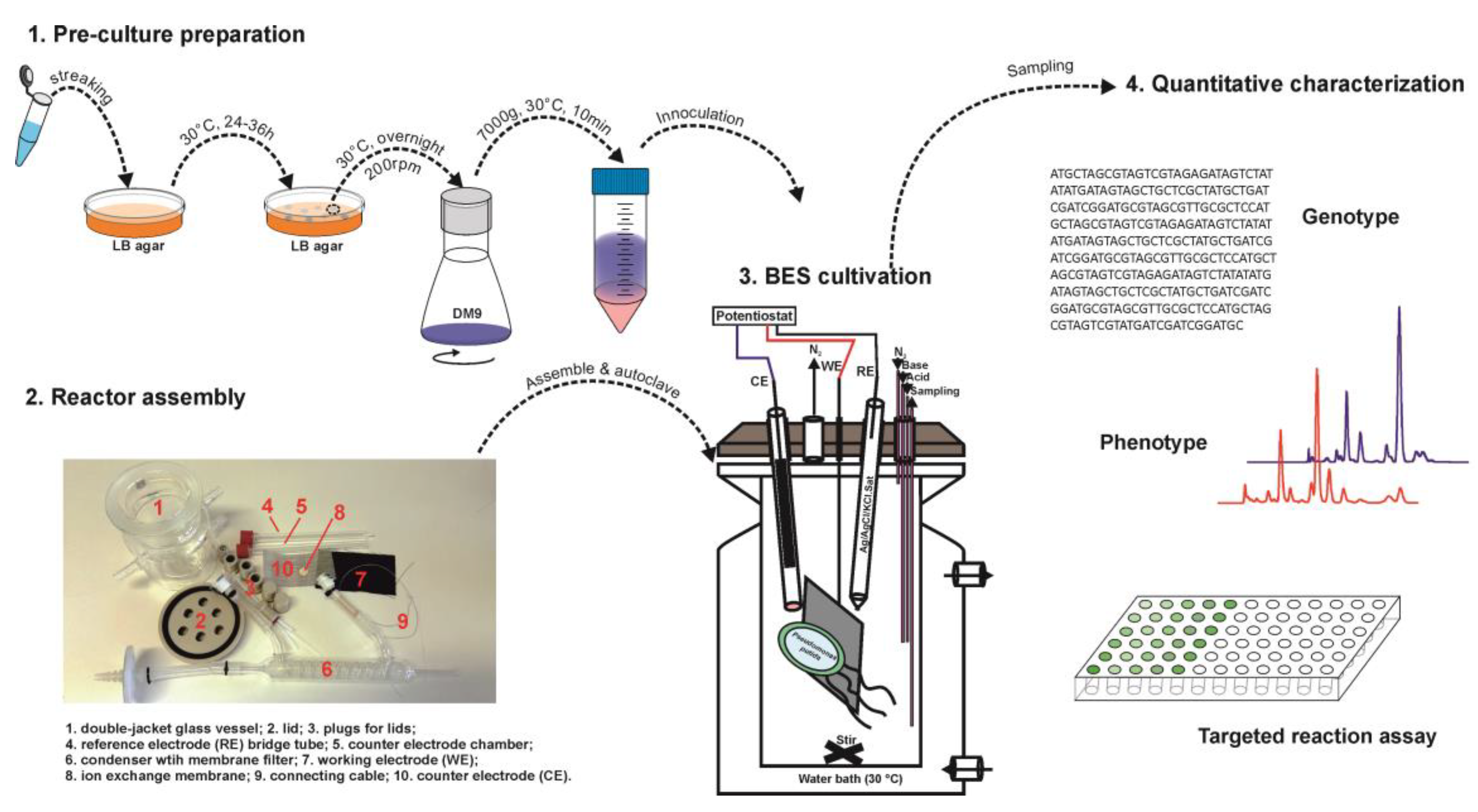
3. Procedure
3.1. Pre-Culture Preparation (Time for Completion: 3 Days, from Day 1 to Day 3)
- Steak a Pseudomonas putida cryo stock on LB-agar plate.NOTE: Single colonies should be visible on the plate after incubation (i) to reduce the heterogeneity of colonies picked for liquid culture and (ii) to check and avoid the contamination on the plate.
- Incubate at 30 °C for 24–36 h.NOTE: longer incubation time will cause a longer lag phase for liquid culture growth.
- Pick up a single colony and inoculate in a baffled Erlenmeyer shaking flask containing DM9 medium.CRITICAL STEP: To improve sufficient oxygen supply, cotton stoppers or membrane vent caps (not silicon-based stoppers) should be used for the gas exchange (see supplementary Figure S2); moreover, the flasks should be filled with medium of <= 20% (identical amount for all batches) of the nominal volume of the flask.
- Incubate the liquid culture overnight (15–16 h);
- Collect the cell pellets by centrifugation at 30 °C, 7000 g, 10 min;
- Resuspend the cell pellets in 15 mL AM buffer and suck the solution in a syringe for immediate injection (Section 3.3)NOTE: Precultures should be timed in a way that cells can be harvested once the reactors are ready for injection (see below)
3.2. Reactor Assembly (Time for Completion: 2 Days, from Day 1 to Day 2)
- 7.
- Assemble the BES reactor accordingly, as the final picture shows in Figure 2.NOTE: The sampling tube on the four-port plug should reach close to the stir bar, while the gassing tube should be above the liquid phase (it is only to gas the headspace). A new working electrode should be used for each batch.
- 8.
- OPTIONAL STEP: plug pH, pO2 or redox sensors into the two spare ports on the lid if necessary.NOTE: Some autoclavable pH sensors were found to be quite sensitive to the electric field after autoclaving. The value can be shifted dramatically (up to 1 pH unit), or become unresponsive after applying the desired potential on the working electrode. This issue can be avoided by sterilizing the pH sensor with 80% ethanol instead of autoclaving.
- 9.
- Fill 50 mL CB buffer into the working chamber.NOTE: For autoclaving purpose. Not AB buffer, because glucose is not autoclavable together with salt.
- 10.
- Fill the counter electrode tube with CB buffer until full.
- 11.
- Fill the bridge tube with saturated KCl solution until full.
- 12.
- Check the gas tightness of the assembled reactor.
![Mps 02 00026 i001]() CRITICAL STEP: The reactor should be gas-tight to prevent the entry of oxygen from the outside atmosphere into the reactor and to minimize the risk of contamination during operation. Procedure to check the gas tightness: connect the gassing tube to gas line, block the condenser and open the sampling tube. The filled-in buffer should be pushed out of the sampling tube if the reactor is air tight. Otherwise, please check the O-rings for each connection.
CRITICAL STEP: The reactor should be gas-tight to prevent the entry of oxygen from the outside atmosphere into the reactor and to minimize the risk of contamination during operation. Procedure to check the gas tightness: connect the gassing tube to gas line, block the condenser and open the sampling tube. The filled-in buffer should be pushed out of the sampling tube if the reactor is air tight. Otherwise, please check the O-rings for each connection. - 13.
- Autoclave the assembled reactor.NOTE: reference electrode and the stainless-steel counter electrode should not be autoclaved. If necessary, carbon cloth and stainless-steel electrode can be cleaned by two-step sonication in solvent (e.g., ethanol or methanol) and sterile distilled water respectively. Reference electrode cannot be sonicated and should only be washed gently with ethanol and water, or be maintained following the manufacturer’s instructions.
3.3. BES Cultivation (Time for Completion: x Days, from Day 2 until Experiment Terminated)
- 14.
- Transfer the autoclaved reactor to a sterilized clean bench.
- 15.
- Remove the liquids inside the working chamber and refill 300 mL AB buffer;
![Mps 02 00026 i001]() CRITICAL STEP: It is important to check that there is no bubble blocking the cation exchange membrane (Nr. 6 in the Figure 2 B) while filling the medium. This is the first of the two most common reasons that will break the electric circuit.
CRITICAL STEP: It is important to check that there is no bubble blocking the cation exchange membrane (Nr. 6 in the Figure 2 B) while filling the medium. This is the first of the two most common reasons that will break the electric circuit. - 16.
- Fix the reference electrode on the bridging tube.
![Mps 02 00026 i001]() CRITICAL STEP: Check the buffer level inside the reference electrode and refill with saturated KCl solution if necessary. This is the second most common reason that will break the circuit. In addition, some KCl crystals should be visible inside the reference electrode and bridging tube, to guarantee the saturation during the experiment.
CRITICAL STEP: Check the buffer level inside the reference electrode and refill with saturated KCl solution if necessary. This is the second most common reason that will break the circuit. In addition, some KCl crystals should be visible inside the reference electrode and bridging tube, to guarantee the saturation during the experiment. - 17.
- Place the counter electrode inside the counter electrode compartment.
- 18.
- Open the gassing tube and connect to a sterile syringe membrane filter (0.22 µm pore size, PTFE).
- 19.
- Transfer the reactor to the working bench and place it on the magnetic stir plate, setup the stirring speed of 400 rpm.NOTE: Stirring speed can be adjusted but has to be consistent for the all batches, unless mass transfer parameters are to be studied. High stirring speed results in a high mass transfer rate in the system.
- 20.
- Connect the double-jacketed chamber to a recirculating heating water bath (set to 30 °C).NOTE: It is important to check the temperature drop while running multiple reactors in parallel. A maximum number (normally 4–6) of reactors should be determined for a given heating circulator system.
- 21.
- Connect the condenser to a recirculating chiller (set to 6 °C).
- 22.
- Connect the gassing port to the nitrogen gasline (flow rate set up to be 20–30 mL/min).
![Mps 02 00026 i001]() CRITICAL STEP: Values chosen in step 21–22 are critical to minimize evaporation of water during operation. For the conditions given above, we measured ~0.09mL water would be lost per hour. This value is essential for the quantitative evaluation (e.g., carbon and electron balance) of the whole system.
CRITICAL STEP: Values chosen in step 21–22 are critical to minimize evaporation of water during operation. For the conditions given above, we measured ~0.09mL water would be lost per hour. This value is essential for the quantitative evaluation (e.g., carbon and electron balance) of the whole system. - 23.
- Connect the working electrode, counter electrode and reference electrode to the potentiostat.
- 24.
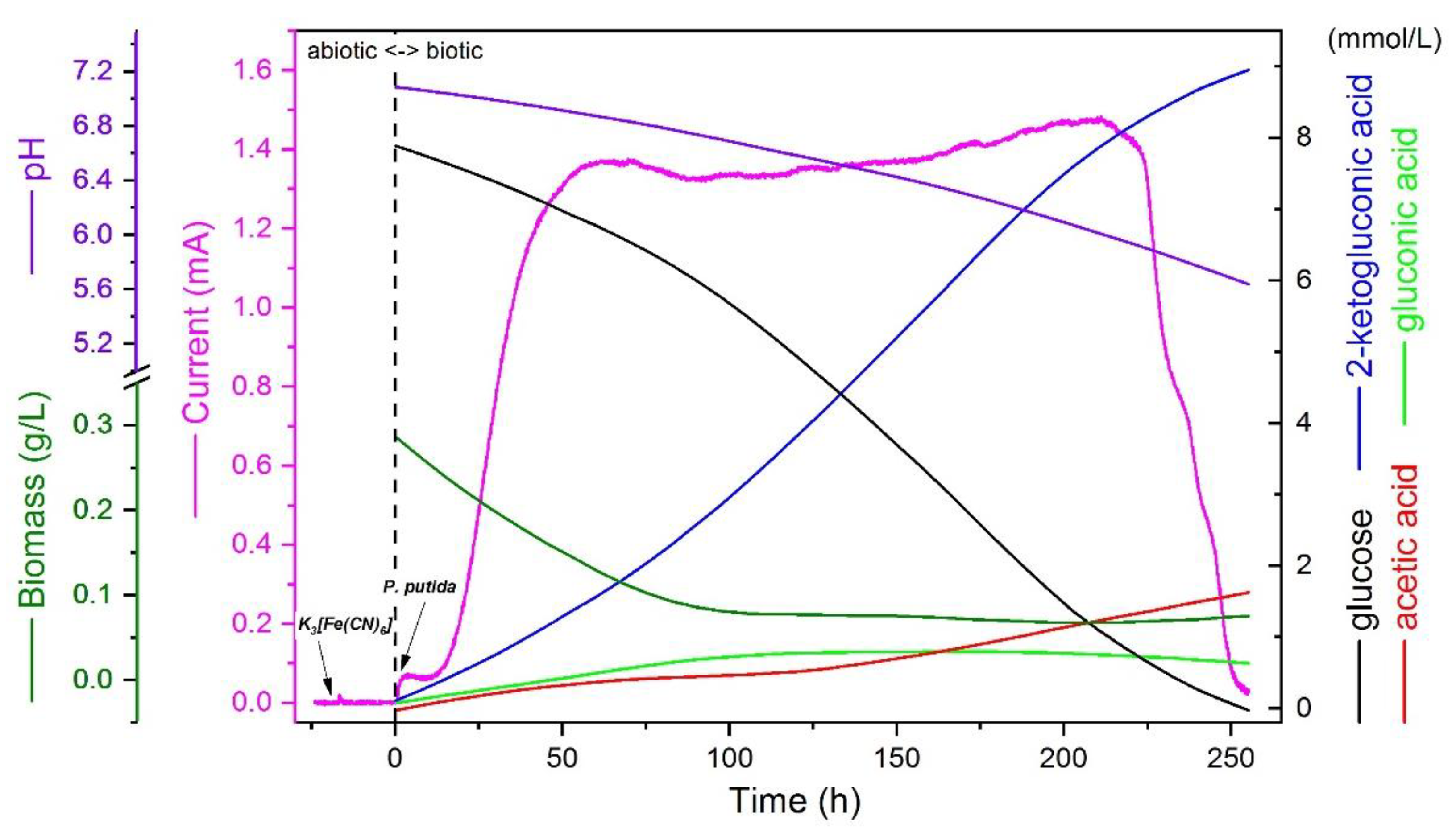
- Start the potentiostat and apply a chronoamperometry method to the BES reactor with the following parameters: working electrode potential (Ewe) of “0.5 V” vs Ag/AgCl/KClsat, current (I) recording of every dI of 100 µA and every dt of 10 min.NOTE: working electrode potential needs to be high enough to efficiently oxidize the mediator, which can be determined by cyclic voltammetry method; 0.5 V is determined for ferricyanide. This value needs to be adjusted when changing mediators, for instance 0.3 V for [Co(bpy)3]Cl3).
- 25.
- Record current for 5–8 h for the fresh AB medium (over the day time of day 2), and a flat background signal should be achieved before the next step;NOTE: Quality control I: The current recorded on the potentiostat for blank AB medium should be around 0 µA fluctuated within a maximum of ±10 µA range. Larger noise background is likely coming from the improper electric connections and/or contaminants present in the buffer or working electrode surface, which needs to be checked.
- 26.
- Inject a final concentration of 1 mM ferricyanide (about 3–5 mL of stock solution) into the working chamber, recording the current for 14–16 h (overnight from day 2 to day 3), and a flat background signal should be achieved before the next step.NOTE: Quality control II: The signal should most likely fluctuate between 0–10 µA, with a maximum up to 20 µA. Otherwise, the system needs to be checked.
- 27.
- Inoculate the BES reactor with the biomass from 3.1, record current until manually stopped;
- 28.
- OPTIONAL STEP: Check the dissolved oxygen level with plugged-in pO2 sensor, and the value should be 0.
- 29.
- OPTIONAL STEP: Control/monitor the pH value of the system.NOTE: While multi-BES reactors are controlled in parallel, one possible issue for the pH system is the cross-interference between different reactors due to the electrical connection of the systems through the potentiostat. The change of applied electrode potential in one reactor can possibly affect the pH sensor in another reactor. Solutions to this issue can be galvanically isolating different pH channels or choosing optical pH measurements.
- 30.
- Sample the reactor once a day (or more frequently) along the batch and collect supernatant and/or cell pellets depending on the analytic purposes;
- 31.
- Apply quantitative approaches for analyzing genotype, phenotype and/or metabolism.
4. Expected Results
Supplementary Materials
Author Contributions
Funding
Conflicts of Interest
References
- Nikel, P.I.; de Lorenzo, V. Pseudomonas putida as a functional chassis for industrial biocatalysis: From native biochemistry to trans-metabolism. Metab. Eng. 2018, 50, 142–155. [Google Scholar] [CrossRef] [PubMed]
- Wackett, L.P. Pseudomonas putida—A versatile biocatalyst. Nat. Biotechnol. 2003, 21, 136–138. [Google Scholar] [CrossRef] [PubMed]
- Nikel, P.I.; Chavarría, M.; Danchin, A.; de Lorenzo, V. From dirt to industrial applications: Pseudomonas putida as a synthetic biology chassis for hosting harsh biochemical reactions. Curr. Opin. Chem. Biol. 2016, 34, 20–29. [Google Scholar] [CrossRef] [PubMed]
- Loeschcke, A.; Thies, S. Pseudomonas putida—A versatile host for the production of natural products. Appl. Microbiol. Biotechnol. 2015, 99, 6197–6214. [Google Scholar] [CrossRef] [PubMed]
- Rich, P.R. The molecular machinery of keilin’s respiratory chain. Biochem. Soc. Trans. 2003, 31, 1095–1105. [Google Scholar] [CrossRef] [PubMed]
- Chen, X.; Alonso, A.P.; Allen, D.K.; Reed, J.L.; Shachar-Hill, Y. Synergy between 13C-metabolic flux analysis and flux balance analysis for understanding metabolic adaptation to anaerobiosis in e. Coli. Metab. Eng. 2011, 13, 38–48. [Google Scholar] [CrossRef] [PubMed]
- Tran, Q.H.; Unden, G. Changes in the proton potential and the cellular energetics of escherichia coli during growth by aerobic and anaerobic respiration or by fermentation. Eur. J. Biochem. 1998, 251, 538–543. [Google Scholar] [CrossRef] [PubMed]
- Noor, E.; Eden, E.; Milo, R.; Alon, U. Central carbon metabolism as a minimal biochemical walk between precursors for biomass and energy. Mol. Cell 2010, 39, 809–820. [Google Scholar] [CrossRef] [PubMed]
- Nikel, P.I.; de Lorenzo, V. Engineering an anaerobic metabolic regime in pseudomonas putida kt2440 for the anoxic biodegradation of 1,3-dichloroprop-1-ene. Metab. Eng. 2013, 15, 98–112. [Google Scholar] [CrossRef] [PubMed]
- Steen, A.; Ütkür, F.Ö.; Borrero-de Acuña, J.M.; Bunk, B.; Roselius, L.; Bühler, B.; Jahn, D.; Schobert, M. Construction and characterization of nitrate and nitrite respiring pseudomonas putida kt2440 strains for anoxic biotechnical applications. J. Biotechnol. 2013, 163, 155–165. [Google Scholar] [CrossRef] [PubMed]
- Schröder, U.; Harnisch, F.; Angenent, L.T. Microbial electrochemistry and technology: Terminology and classification. Energy Environ. Sci. 2015, 8, 513–519. [Google Scholar] [CrossRef]
- Park, D.H.; Zeikus, J.G. Impact of electrode composition on electricity generation in a single-compartment fuel cell using shewanella putrefaciens. Appl. Microbiol. Biotechnol. 2002, 59, 58–61. [Google Scholar] [PubMed]
- Reguera, G.; McCarthy, K.D.; Mehta, T.; Nicoll, J.S.; Tuominen, M.T.; Lovley, D.R. Extracellular electron transfer via microbial nanowires. Nature 2005, 435, 1098–1101. [Google Scholar] [CrossRef] [PubMed]
- Rabaey, K.; Boon, N.; Hofte, M.; Verstraete, W. Microbial phenazine production enhances electron transfer in biofuel cells. Environ. Sci. Technol. 2005, 39, 3401–3408. [Google Scholar] [CrossRef] [PubMed]
- Light, S.H.; Su, L.; Rivera-Lugo, R.; Cornejo, J.A.; Louie, A.; Iavarone, A.T.; Ajo-Franklin, C.M.; Portnoy, D.A. A flavin-based extracellular electron transfer mechanism in diverse gram-positive bacteria. Nature 2018, 562, 140–144. [Google Scholar] [CrossRef] [PubMed]
- Lai, B.; Yu, S.; Bernhardt, P.V.; Rabaey, K.; Virdis, B.; Krömer, J.O. Anoxic metabolism and biochemical production in pseudomonas putida f1 driven by a bioelectrochemical system. Biotechnol. Biofuels 2016, 9, 39. [Google Scholar] [CrossRef] [PubMed]
- Hintermayer, S.; Yu, S.; Krömer, J.O.; Weuster-Botz, D. Anodic respiration of pseudomonas putida kt2440 in a stirred-tank bioreactor. Biochem. Eng. J. 2016, 115, 1–13. [Google Scholar] [CrossRef]
- Rosa, L.F.M.; Hunger, S.; Gimkiewicz, C.; Zehnsdorf, A.; Harnisch, F. Paving the way for bioelectrotechnology: Integrating electrochemistry into bioreactors. Eng. Life Sci. 2017, 17, 77–85. [Google Scholar] [CrossRef]


© 2019 by the authors. Licensee MDPI, Basel, Switzerland. This article is an open access article distributed under the terms and conditions of the Creative Commons Attribution (CC BY) license (http://creativecommons.org/licenses/by/4.0/).
Share and Cite
Lai, B.; Nguyen, A.V.; Krömer, J.O. Characterizing the Anoxic Phenotype of Pseudomonas putida Using a Bioelectrochemical System. Methods Protoc. 2019, 2, 26. https://doi.org/10.3390/mps2020026
Lai B, Nguyen AV, Krömer JO. Characterizing the Anoxic Phenotype of Pseudomonas putida Using a Bioelectrochemical System. Methods and Protocols. 2019; 2(2):26. https://doi.org/10.3390/mps2020026
Chicago/Turabian StyleLai, Bin, Anh Vu Nguyen, and Jens O Krömer. 2019. "Characterizing the Anoxic Phenotype of Pseudomonas putida Using a Bioelectrochemical System" Methods and Protocols 2, no. 2: 26. https://doi.org/10.3390/mps2020026
APA StyleLai, B., Nguyen, A. V., & Krömer, J. O. (2019). Characterizing the Anoxic Phenotype of Pseudomonas putida Using a Bioelectrochemical System. Methods and Protocols, 2(2), 26. https://doi.org/10.3390/mps2020026