
Novel Computational Design of Polymer Micromachined Insect-Mimetic Wings for Flapping-Wing Nano Air Vehicles


Abstract
1. Introduction
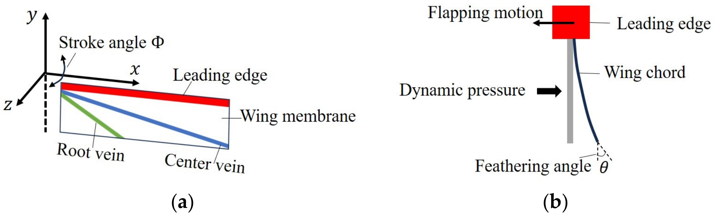
2. Our 2.5-Dimensional Insect-Mimetic Micro Wing Model Fabricable Using Polymer Micromachining
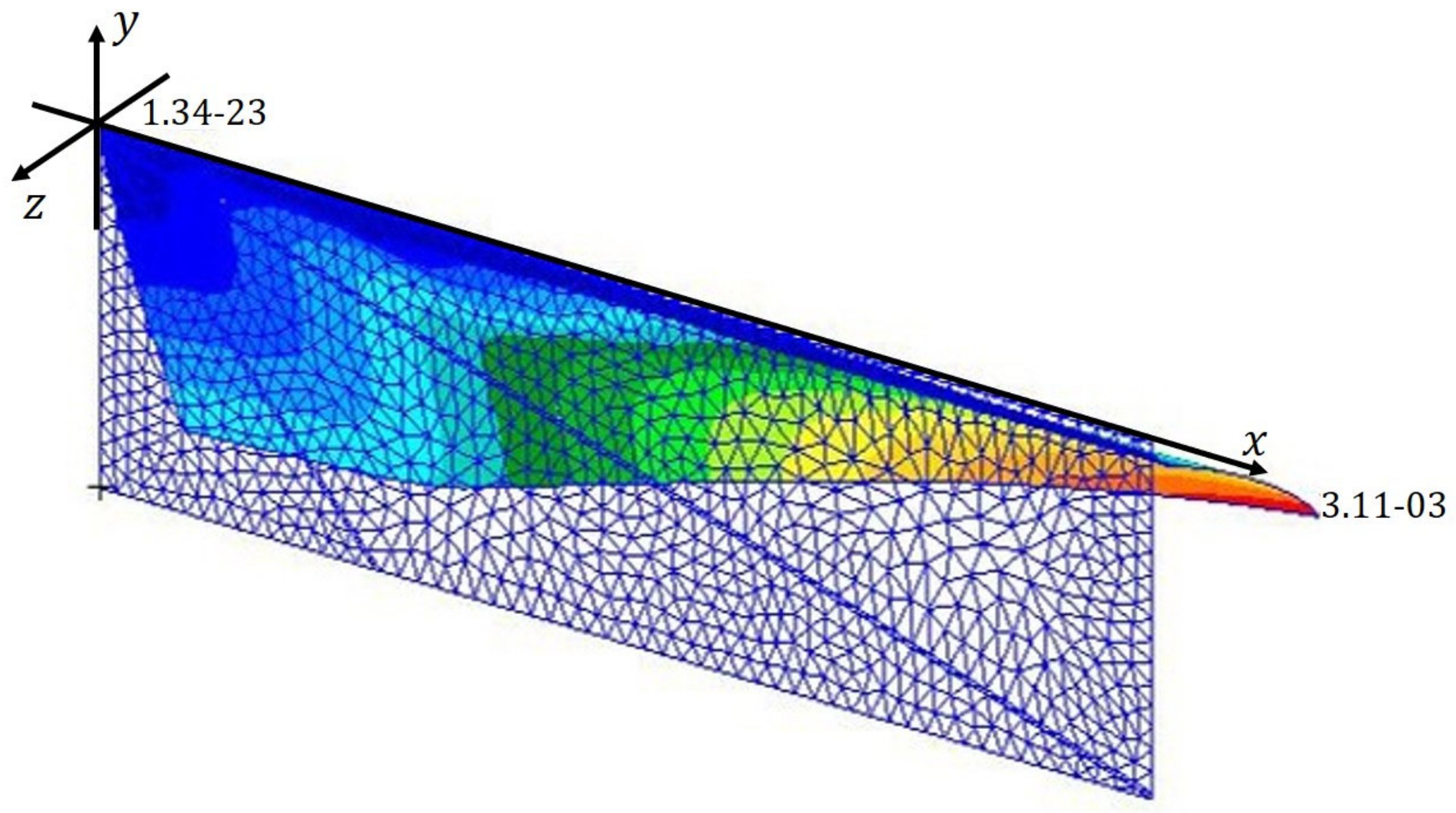
3. Nonlinear Finite-Element Solution Procedure for Shell Structures with Large Deformation for the Insect-Mimetic Micro Wing Model
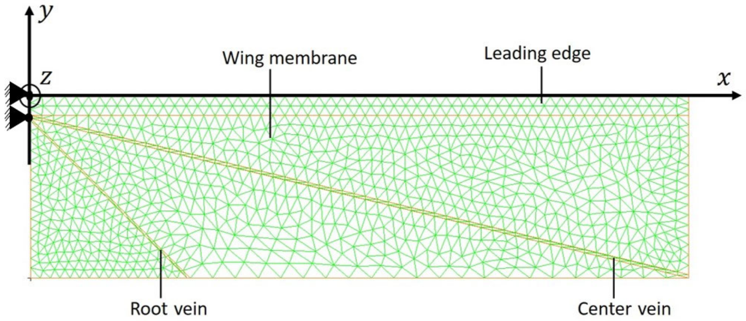
4. Numerical Implementation of the Insect-Mimetic Micro Wing Model
5. Computational Design Based on Design Windows
5.1. Design Window Search Approach
5.2. Structural Design for IMMW Model
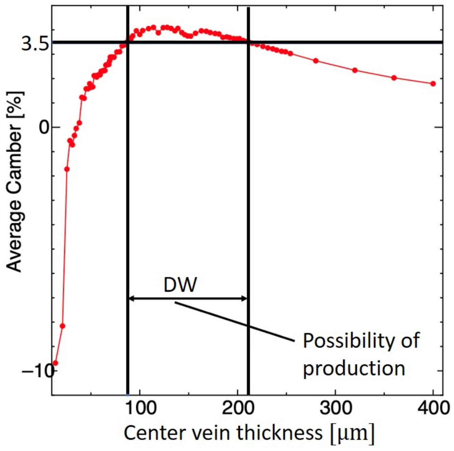
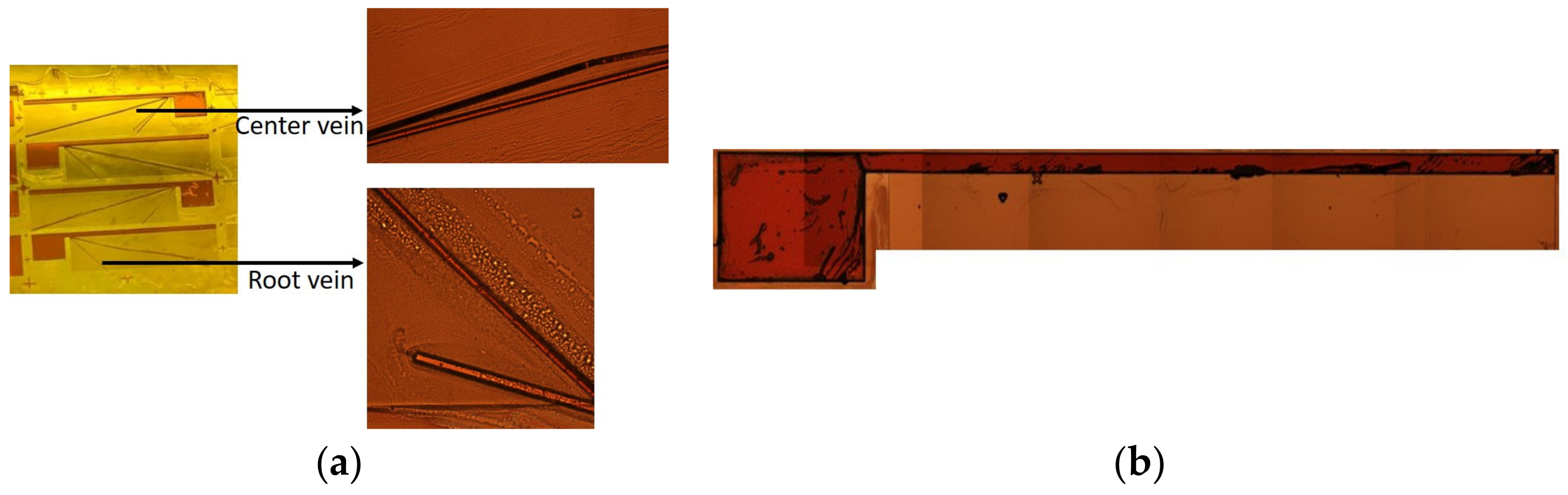
5.2.1. Center Vein
5.2.2. Leading Edge
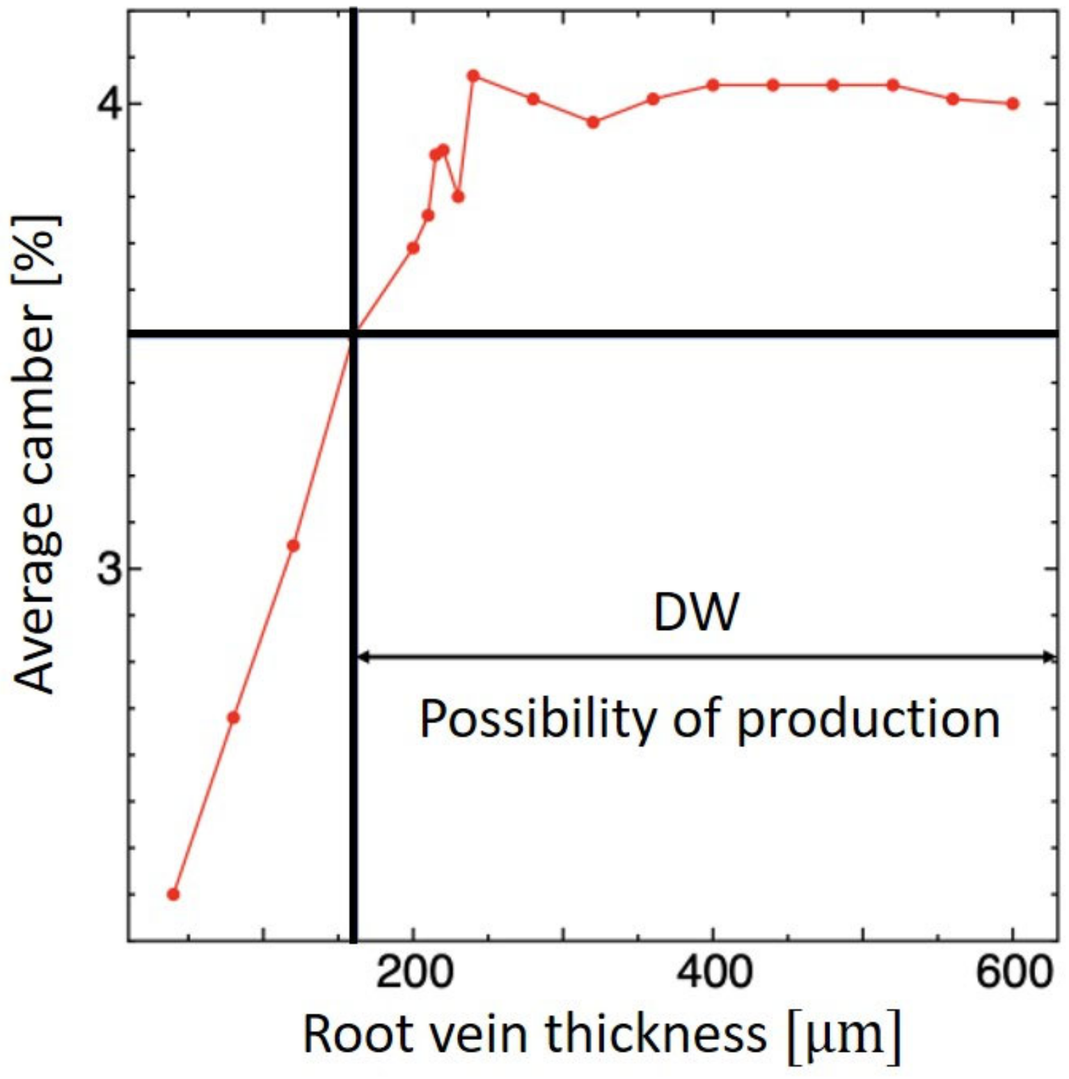
5.2.3. Root Vein
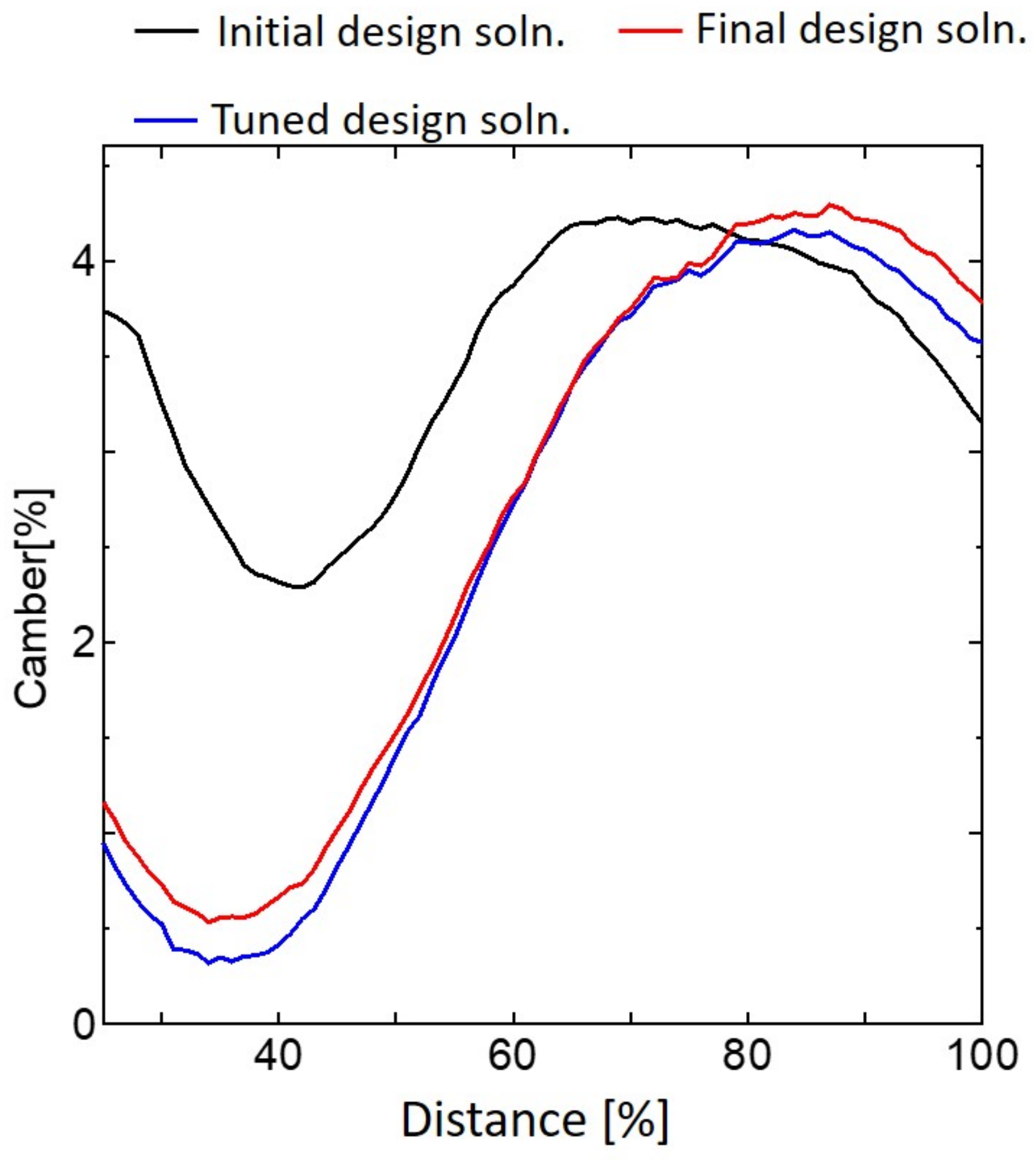
5.3. Final Design Solution for the Insect-Mimetic Micro Wing Model Taking into Account Fabrication Conditions
6. Concluding Remarks
Author Contributions
Funding
Institutional Review Board Statement
Data Availability Statement
Acknowledgments
Conflicts of Interest
References
- Ellington, C.P. The Aerodynamics of Hovering Insect Flight. III. Kinematics. Philos. Trans. R. Soc. Lond. B 1984, 305, 41–78. [Google Scholar]
- Brodsky, A.K. The Evolution of Insect Flight; Oxford Science Publication: Oxford, UK, 1994. [Google Scholar]
- Sane, S.P. The aerodynamics of insect flight. J. Exp. Biol. 2003, 206, 4191–4208. [Google Scholar] [CrossRef]
- Hilton, T.; Martin, C.; Tun, R.; Castelli, V. The DARPA Nano Air Vehicle Program. In Proceedings of the 50th AIAA Aerospace Sciences Meeting including the New Horizons Forum and Aerospace Exposition, Nashville, TN, USA, 9–12 January 2012. [Google Scholar]
- Galinski, C.; Zbikowski, R. Some problems of micro air vehicles development. Bull. Pol. Acad. Sci. Technical. Sci. 2007, 55, 91–98. [Google Scholar]
- Paulsen, D.H. Nano UAS—An upcoming reality. In Proceedings of the 24th International Unmanned Air Vehicles Conference, Bristol, UK, 4–7 June 2009. [Google Scholar]
- Bachmann, R.J. Biologically inspired mechanisms facilitating multi modal locomotion for areal micro-robot. In Proceedings of the 24th International Unmanned Air Vehicles Conference, Bristol, UK, 30 March–1 April 2009. [Google Scholar]
- Serokhvostov, S.V. Ways and technologies required for MAV miniaturization. In Proceedings of the European Micro Air Vehicle Conference (EMAV ’08), Braunschweig, Germany, 8–10 July 2008. [Google Scholar]
- Shyy, W.; Lian, Y.; Tang, J.; Liu, H.; Trizila, P.; Stanford, B.; Bernal, L.; Cesnik, C.; Friedmann, P.; Ifju, P. Computational aerodynamics of low Reynolds number plunging, pitching and flexible wings for MAV applications. Acta Mech. Sin. 2008, 24, 351–373. [Google Scholar] [CrossRef]
- Wood, R.J.; Finio, B.; Karpelson, M.; Ma, K.; Pérez-Arancibia, N.O.; Sreetharan, P.S.; Tanaka, H.; Whitney, J.P. Progress on ‘pico’ air vehicles. Int. J. Robot. Res. 2012, 31, 1292–1302. [Google Scholar] [CrossRef]
- Dudely, R. The Biomechanics of Insect Flight: Form, Function and Evolution; Princeton University Press: Princeton, NJ, USA, 1999. [Google Scholar]
- Wood, R.J. The First Takeoff of a Biologically Inspired At-Scale Robotic Insect. IEEE Trans. Robot. 2008, 24, 341–347. [Google Scholar] [CrossRef]
- Ennos, A.R. The importance of torsion in the design of insect wings. J. Exp. Biol. 1988, 140, 137–160. [Google Scholar] [CrossRef]
- Wootton, R.J.; Herbert, R.C.; Young, P.G.; Evans, K.E. Approaches to the structural modelling of insect wings. Philos. Trans. R. Soc. Lond. B 2003, 358, 1577–1587. [Google Scholar] [CrossRef] [PubMed]
- Du, G.; Sun, M. Effects of wing deformation on aerodynamic forces in hovering hoverflies. J. Exp. Biol. 2010, 213, 2273–2283. [Google Scholar] [CrossRef]
- Wang, Q.; Goosen, J.; van Keulen, F. An efficient fluid–structure interaction model for optimizing twistable flapping wings. J. Fluids Struct. 2017, 73, 82–99. [Google Scholar] [CrossRef]
- Haoyuan, S.; Daochun, L.; Zi, K.; Huadong, L.; Dian, Y.; Jinwu, X. Influence of wing camber on aerodynamic performance of flapping wing rotor. Aerosp. Sci. Technol. 2021, 113, 106732. [Google Scholar]
- Nakata, T.; Noda, R.; Liu, H. Effect of twist, camber and spanwise bending on the aerodynamic performance of flapping wings. J. Biomech. Sci. Eng. 2018, 13, 17–00618. [Google Scholar] [CrossRef]
- ShuaiShuai, W.; YinHu, Q.; ZhiQiang, Z. Influence of camber on aerodynamic performance of airfoil based on CFD technology. J. Phys.: Conf. Ser. 2022, 2022, 2276. [Google Scholar] [CrossRef]
- Zhang, X.; Wang, G.G.; Zhang, M.J.; Li, W. Effect of relative camber on the aerodynamic performance improvement of asymmetrical blunt trailing-edge modification. J. Eng. Thermophys. 2017, 26, 514–531. [Google Scholar] [CrossRef]
- Whitney, J.P.; Wood, R.J. Conceptual design of flapping wing micro air vehicles. Bioinspir. Biomim. 2012, 7, 036001. [Google Scholar] [CrossRef] [PubMed]
- Combes, S.A.; Daniel, T.L. Into thin air: Contributions of aerodynamic and inertial-elastic forces to wing bending in the hawkmoth Manduca sexta. J. Exp. Biol. 2003, 206, 2999–3006. [Google Scholar] [CrossRef]
- E Mengesha, T.; Vallance, R.R.; Barraja, M.; Mittal, R. Parametric structural modeling of insect wings. Bioinspir. Biomim. 2009, 4, 036004. [Google Scholar] [CrossRef]
- Sunada, S.; Zeng, L.; Kawachi, K. The relationship between dragonfly wing structure and torsional deformation. J. Theor. Biol. 1998, 193, 39–45. [Google Scholar] [CrossRef]
- Tanaka, H.; Wood, R.J. Fabrication of corrugated artificial insect wings using laser micromachined molds. J. Micromech. Microeng. 2010, 20, 075008. [Google Scholar] [CrossRef]
- Wootton, R.J. Functional morphology of insect wings. Annu. Rev. Entomol. 1992, 37, 113–140. [Google Scholar] [CrossRef]
- Wang, X.-S.; Li, Y.; Shi, Y.-F. Effects of sandwich microstructures on mechanical behaviors of dragonfly wing vein. Compos. Sci. Technol. 2008, 68, 186–192. [Google Scholar] [CrossRef]
- Available online: https://www.electronics.toray/en/ (accessed on 1 October 2020).
- Ishihara, D. Computational approach for the fluid-structure interaction design of insect-inspired micro flapping wings. Fluids 2022, 7, 26. [Google Scholar] [CrossRef]
- Ishihara, D.; Suetsugu, R.; Ramegowda, P.C. One-wing polymer micromachined transmission for insect-inspired flapping wing nano air vehicles. Eng. Res. Express 2021, 3, 045006. [Google Scholar]
- Ishihara, D.; Onishi, M.; Sugikawa, K. Vein–membrane interaction in cambering of flapping insect wings. Biomimetics 2023, 8, 571. [Google Scholar] [CrossRef] [PubMed]
- Ishihara, D.; Onishi, M. Computational fluid-structure interaction framework for passive feathering and cambering in flap-ping insect wings. Int. J. Numer. Methods Fluids 2023, 2023, 1–47. [Google Scholar]
- Liu, H.; Wang, S.; Liu, T. Vortices and Forces in Biological Flight: Insects, Birds, and Bats. Annu. Rev. Fluid Mech. 2024, 56, 147–170. [Google Scholar] [CrossRef]
- Wootton, R.J. Support and deformability in insect wings. J. Zool. Lond. 1981, 193, 447–468. [Google Scholar] [CrossRef]
- Walker, S.M.; Thomas, A.L.R.; Taylor, G.K. Deformable wing kinematics in free-flying hoverflies. J. R. Soc. Interface 2010, 7, 131–142. [Google Scholar] [CrossRef]
- Dickinson, M.H.; Lehmann, F.-O.; Sane, S.P. Wing Rotation and the Aerodynamic Basis of Insect Flight. Science 1999, 284, 1954–1960. [Google Scholar] [CrossRef]
- Ishihara, D.; Horie, T.; Niho, T. An experimental and three-dimensional computational study on the aerodynamic contribution to the passive pitching motion of flapping wings in hovering flies. Bioinspir. Biomim. 2014, 9, 046009. [Google Scholar] [CrossRef]
- Tanaka, H.; Whitney, J.P.; Wood, R.J. Effect of Flexural and Torsional Wing Flexibility on Lift Generation in Hoverfly Flight. Integr. Comp. Biol. 2011, 51, 142–150. [Google Scholar] [CrossRef] [PubMed]
- Rashmikant; Ishihara, D. Iterative design window search for polymer micromachined flapping-wing nano air vehicles using nonlinear dynamic analysis. Int. J. Mech. Mater. Des. 2023, 19, 407–429. [Google Scholar] [CrossRef]
- Ennos, A.R. The Kinematics and Aerodynamics of the Free Flight of Some Diptera. J. Exp. Biol. 1989, 142, 49–85. [Google Scholar] [CrossRef]


| Thickness () | Avg. Camber (%) | Max. Camber (%) | Feathering Angle () |
|---|---|---|---|
| 120 | 4.13 | 5.47 | 15.78 |
| 160 | 4.11 | 5.09 | 14.07 |
| 200 | 3.60 | 4.49 | 11.61 |
| Thickness () | Avg. Camber (%) | Mass () |
|---|---|---|
| 160 | 3.50 | 1.96 |
| 200 | 3.69 | 1.97 |
| 240 | 4.06 | 1.98 |
Disclaimer/Publisher’s Note: The statements, opinions and data contained in all publications are solely those of the individual author(s) and contributor(s) and not of MDPI and/or the editor(s). MDPI and/or the editor(s) disclaim responsibility for any injury to people or property resulting from any ideas, methods, instructions or products referred to in the content. |
© 2024 by the authors. Licensee MDPI, Basel, Switzerland. This article is an open access article distributed under the terms and conditions of the Creative Commons Attribution (CC BY) license (https://creativecommons.org/licenses/by/4.0/).
Share and Cite
Shankar, V.; Shirakawa, N.; Ishihara, D. Novel Computational Design of Polymer Micromachined Insect-Mimetic Wings for Flapping-Wing Nano Air Vehicles. Biomimetics 2024, 9, 133. https://doi.org/10.3390/biomimetics9030133
Shankar V, Shirakawa N, Ishihara D. Novel Computational Design of Polymer Micromachined Insect-Mimetic Wings for Flapping-Wing Nano Air Vehicles. Biomimetics. 2024; 9(3):133. https://doi.org/10.3390/biomimetics9030133
Chicago/Turabian StyleShankar, Vinay, Nagi Shirakawa, and Daisuke Ishihara. 2024. "Novel Computational Design of Polymer Micromachined Insect-Mimetic Wings for Flapping-Wing Nano Air Vehicles" Biomimetics 9, no. 3: 133. https://doi.org/10.3390/biomimetics9030133
APA StyleShankar, V., Shirakawa, N., & Ishihara, D. (2024). Novel Computational Design of Polymer Micromachined Insect-Mimetic Wings for Flapping-Wing Nano Air Vehicles. Biomimetics, 9(3), 133. https://doi.org/10.3390/biomimetics9030133