


Simulation and Optimization Study on the Ventilation Performance of High-Rise Buildings Inspired by the White Termite Mound Chamber Structure


Abstract
:1. Introduction
2. Materials and Methods
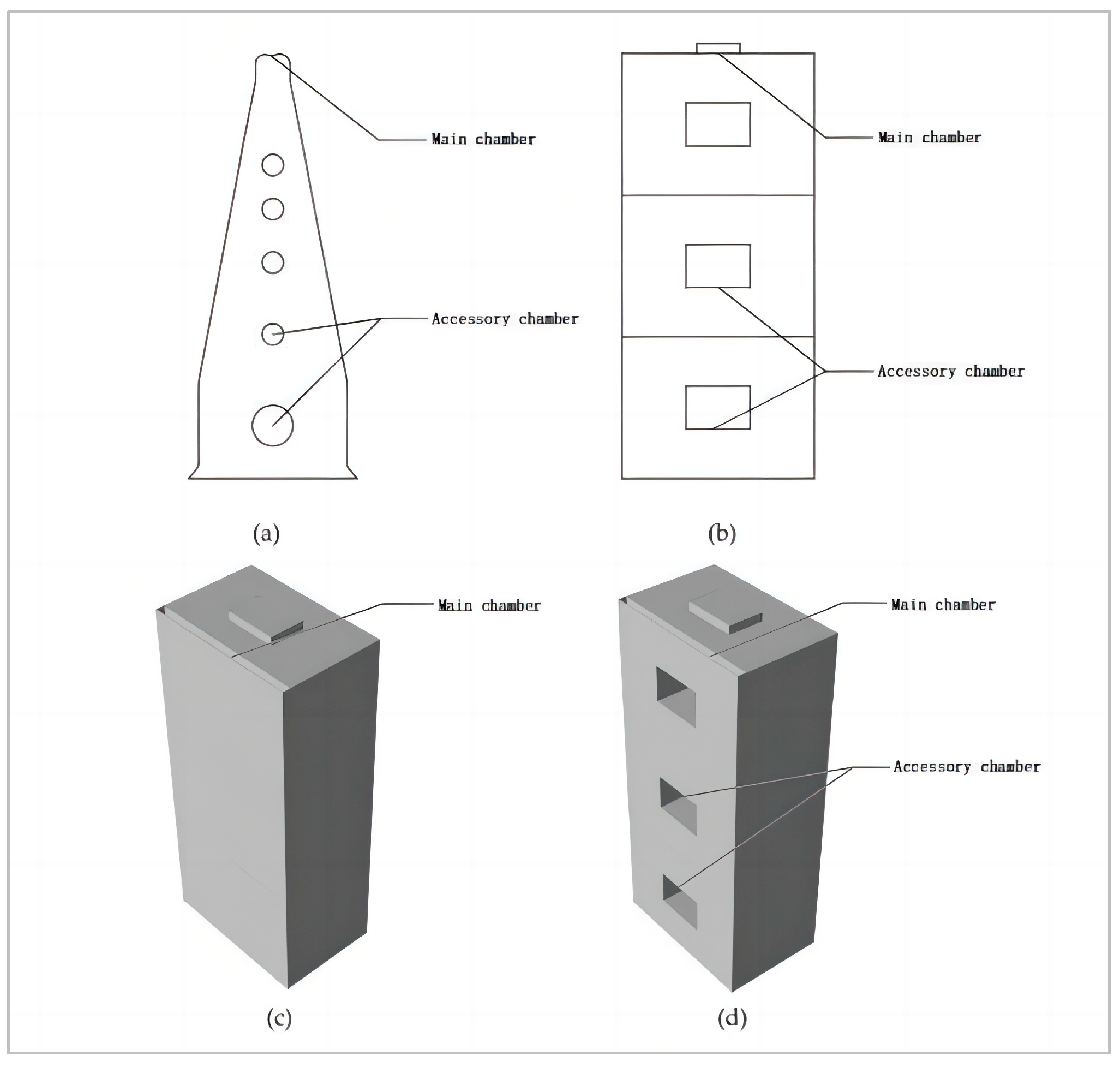
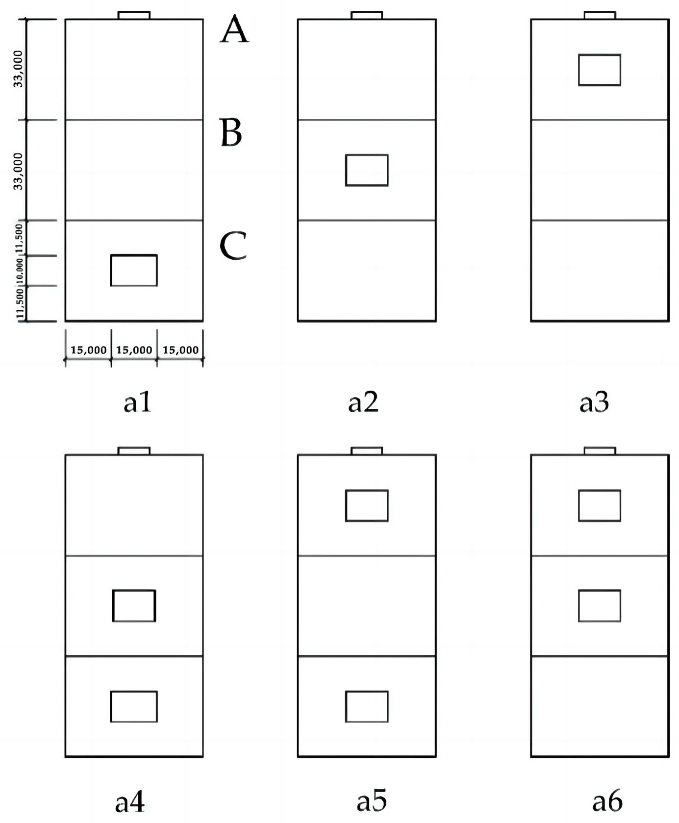
2.1. Object of Study: High-Rise Building Modeling
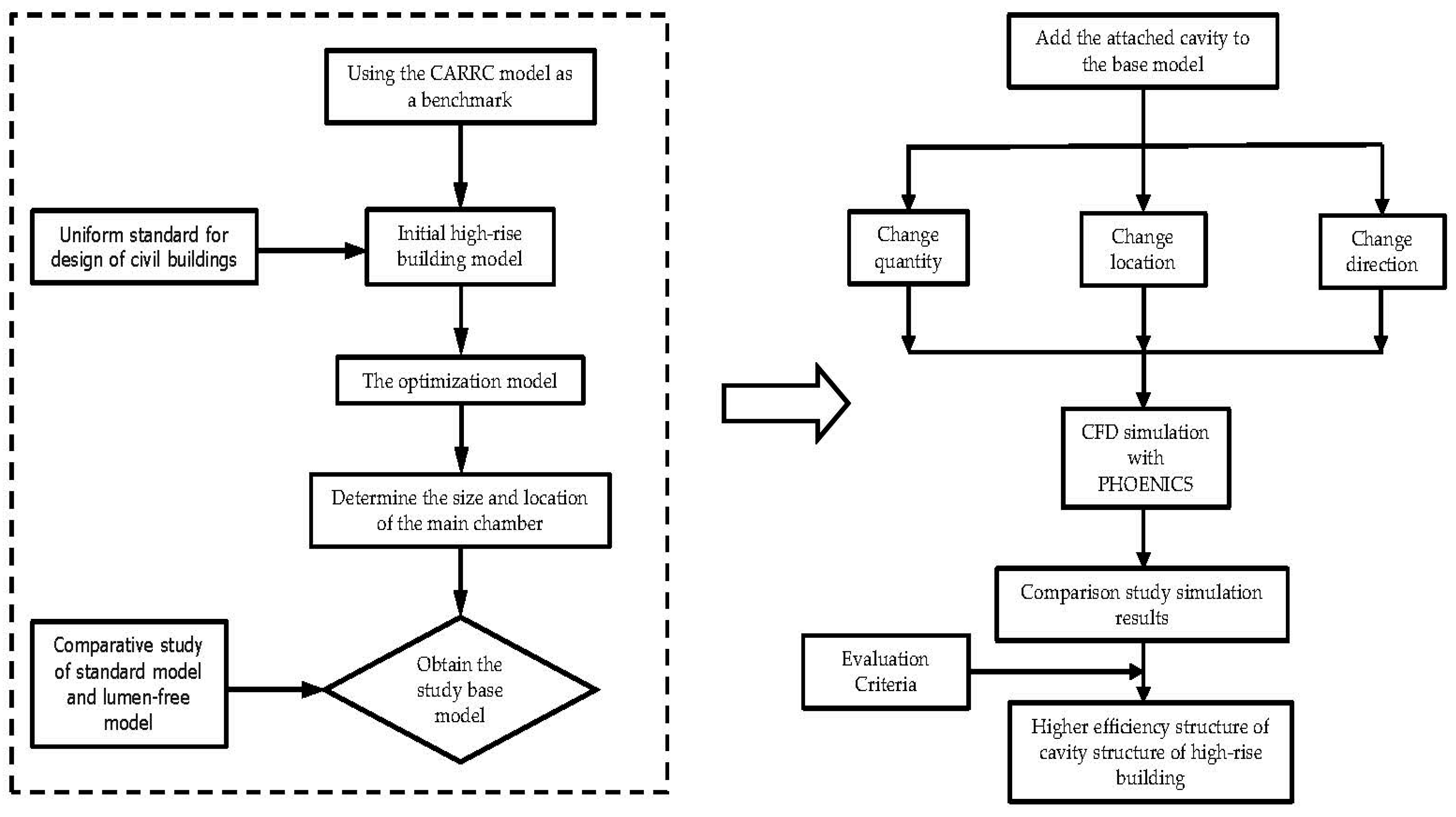
2.2. Research Process
2.3. Evaluation Methodology and CFD Simulation Details
2.3.1. Evaluation Methodology
- Average indoor air velocity: the average air velocity of the cutoff plane at 1.0 m of the main working height of the human body in the functional rooms of each floor is selected as an evaluation index for analysis. Relevant research results show that when the indoor air velocity reaches 0.20~0.30 m/s, it can ensure a human physiological sensation in the comfortable range. The results of related research show that when the indoor air velocity reaches 0.20~0.30 m/s, it can make people feel comfortable [21];
- According to the code and previous research, the difference in wind pressure between the windward and leeward sides of a building exceeding 3 pa is used as an evaluation criterion for natural ventilation indoors [22];
- In this study, the CFD simulation data of the 11th standard floor, the 22nd standard floor, and the 33rd standard floor of the standard high-rise building model are used as the main evaluation basis for the average wind speed at the standard floor.
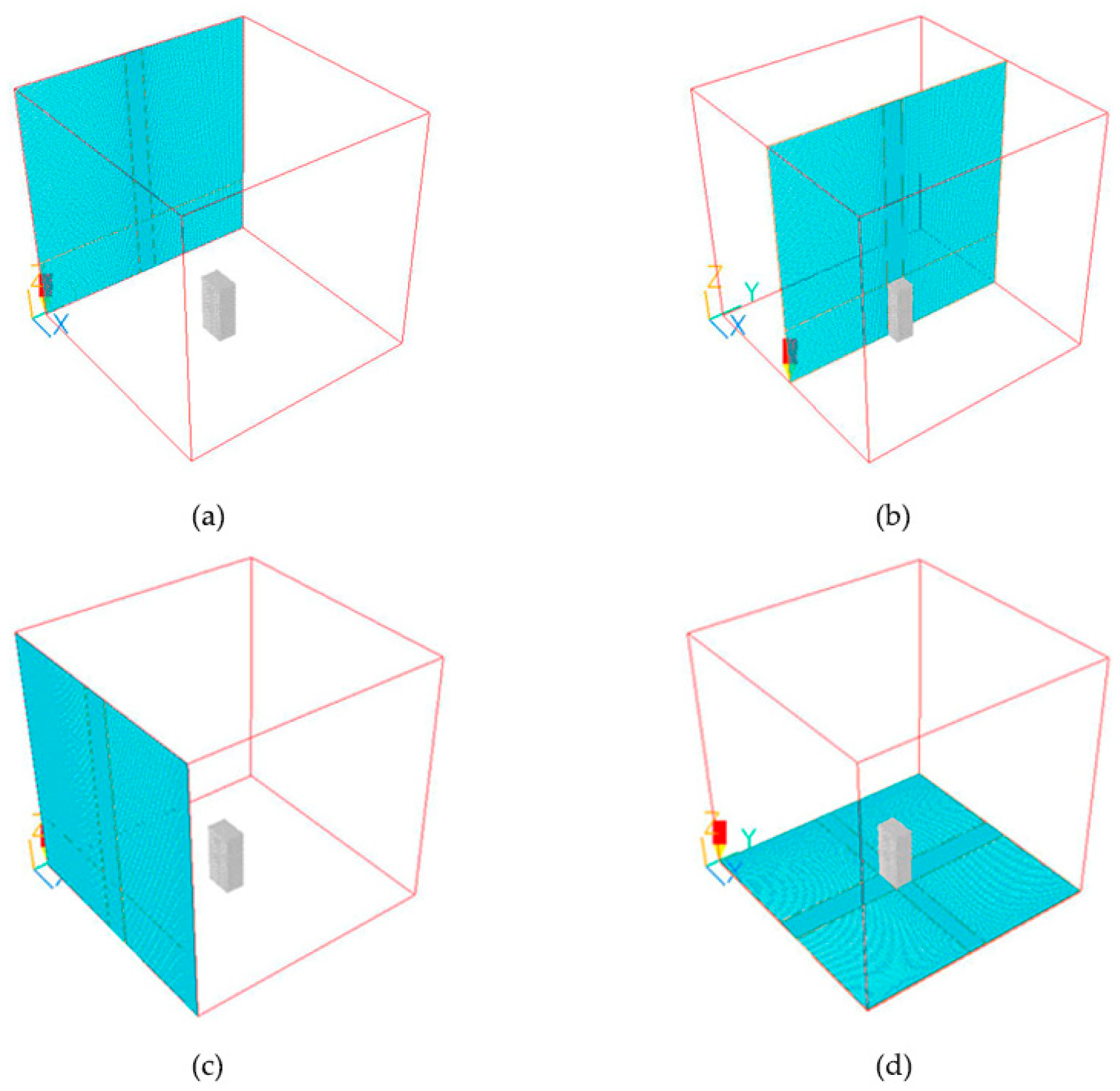
2.3.2. CFD Simulation Details
3. Results
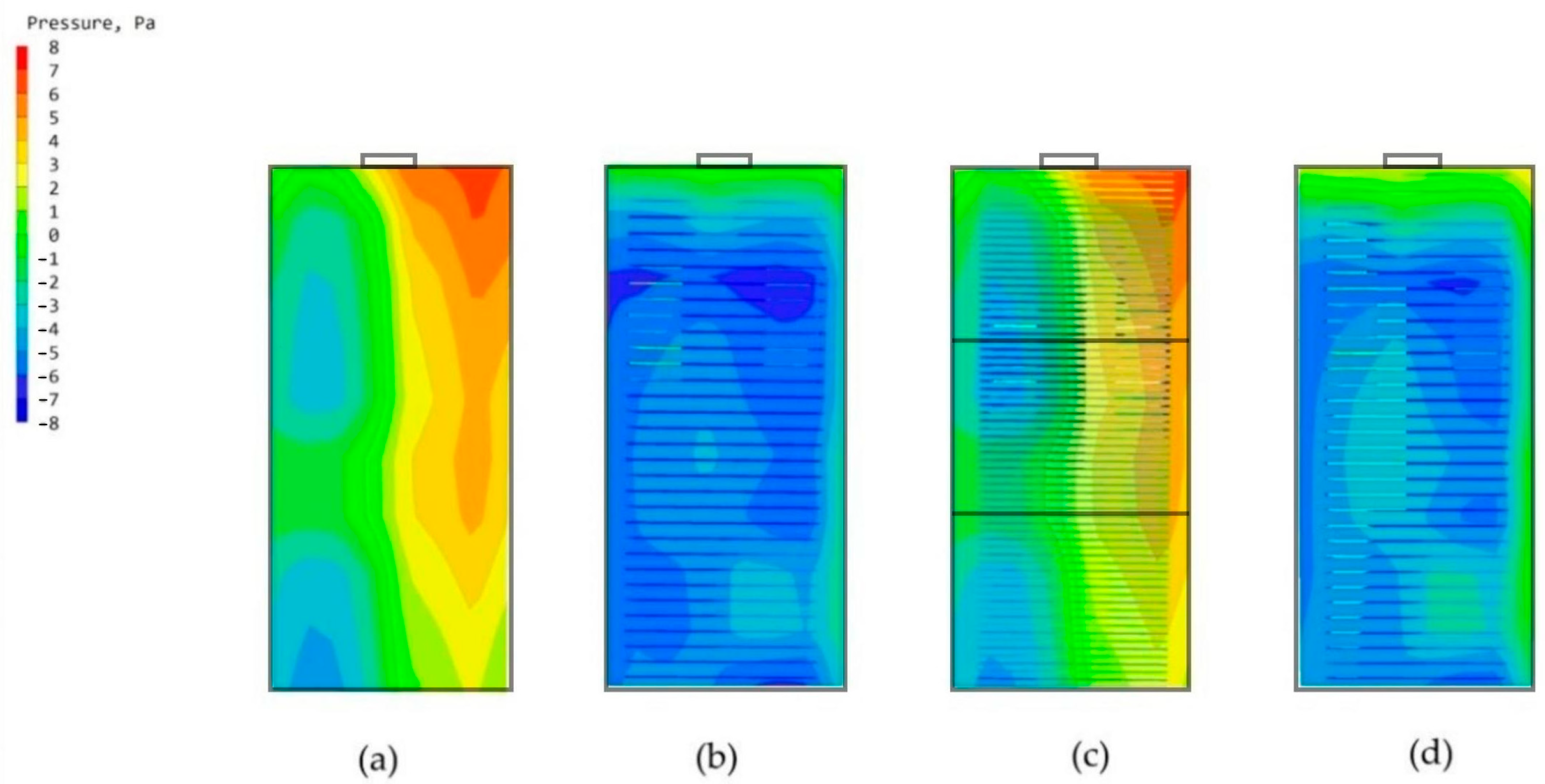
3.1. Comparative Study of High-Rise Building Models without Chambers and High-Rise Building Models with Main Chambers
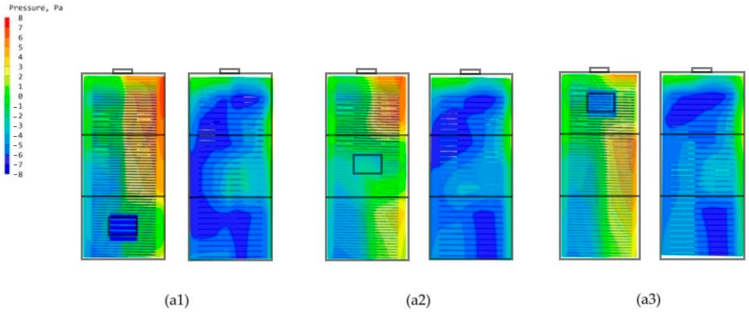
3.2. Study of Single-Attached Chambers at Different Locations
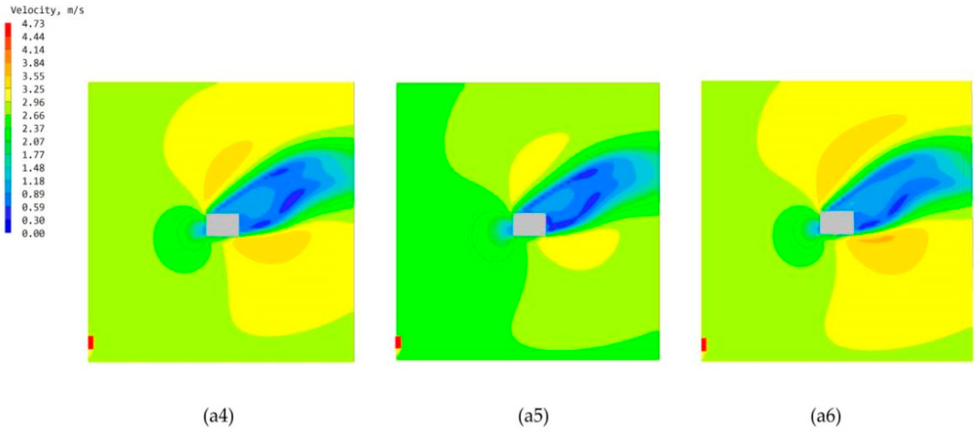
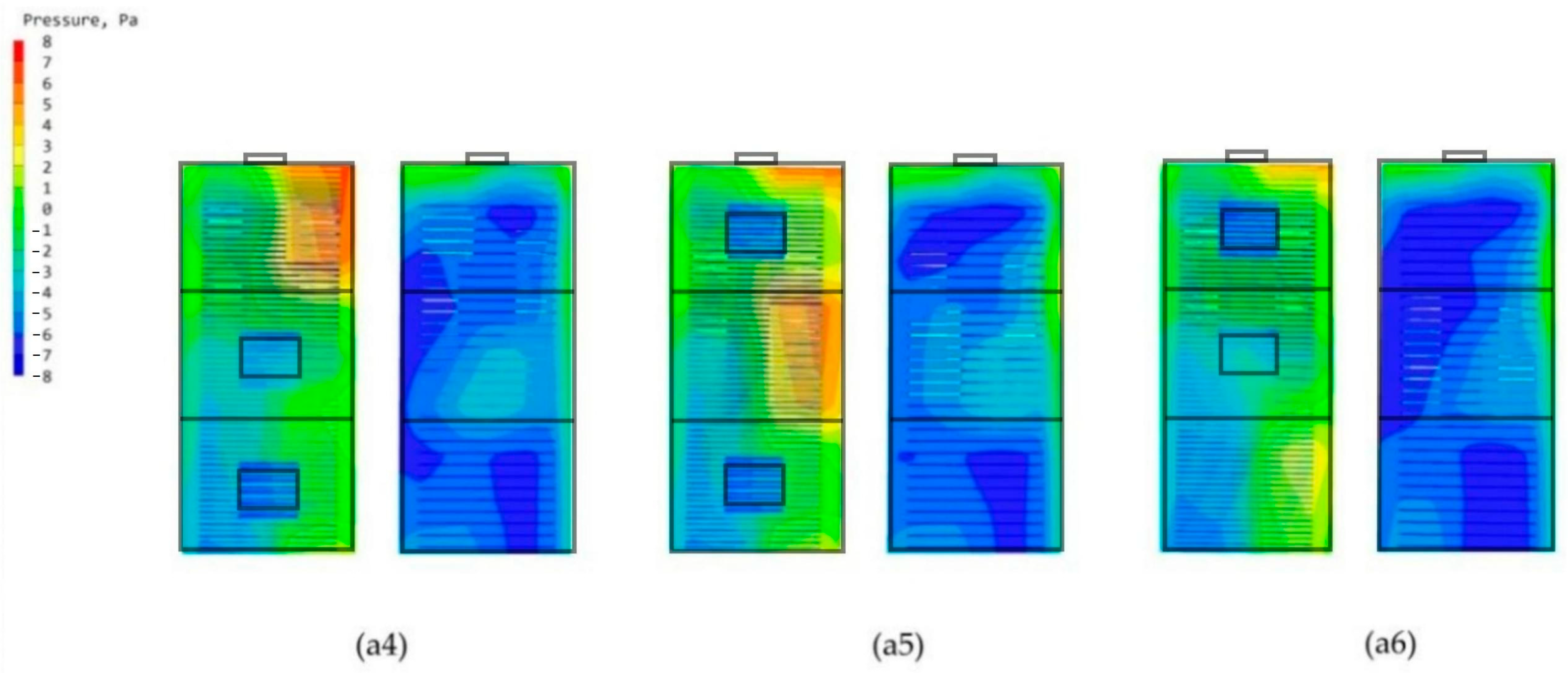
3.3. Study of Double-Attached Chambers in Different Arrangements
4. Discussion
5. Conclusions
Author Contributions
Funding
Institutional Review Board Statement
Data Availability Statement
Acknowledgments
Conflicts of Interest
References
- van Druenen, T.; van Hooff, T.; Montazeri, H.; Blocken, B. CFD evaluation of building geometry modifications to reduce pedestrian-level wind speed. Build. Environ. 2019, 163, 106293. [Google Scholar] [CrossRef]
- Tang, R.; Wang, S.; Sun, S. Impacts of technology-guided occupant behavior on air-conditioning system control and building energy use. Build. Simul. 2021, 14, 209–217. [Google Scholar] [CrossRef]
- Paejaroen, P.; Phaenark, C.; Chunchob, S.; Sawangproh, W. Morphological and Physicochemical Properties of Termite Mounds in the Mixed Deciduous Forests of Thailand. Floresta Ambiente 2021, 28, e20210040. [Google Scholar] [CrossRef]
- Fagundes, T.M.; Ordonez, J.C.; Yaghoobian, N. The role of mound functions and local environment in the diversity of termite mound structures. J. Theor. Biol. 2021, 527, 110823. [Google Scholar] [CrossRef] [PubMed]
- de Freitas, D.F.; Ker, J.C.; da Silva Filho, L.A.; Pereira, T.T.C.; de Souza, O.F.F.; Schaefer, C.E.G.R. Pedogeomorphology and paleoenvironmental implications of large termite mounds at the Brazilian semiarid landscape. Geomorphology 2021, 387, 107762. [Google Scholar] [CrossRef]
- Kusumawardhani, D.; Nandika, D.; Karlinasari, L.; Arinana, A.; Batubara, I. Architectural and physical properties of fungus comb from subterranean termite Macrotermes gilvus (Isoptera: Termitidae) mound. Biodiversitas J. Biol. Divers. 2021, 22, 1627–1634. Available online: https://smujo.id/biodiv/article/view/7311 (accessed on 24 August 2022). [CrossRef]
- Andréen, D.; Soar, R. Termite-inspired metamaterials for flow-active building envelopes. Front. Mater. 2023, 10, 1126974. [Google Scholar] [CrossRef]
- Zhou, K.; Li, F.; Cai, H.; Yang, Y.; Peng, F.; Chen, L.; Zhuang, J. Experimental and numerical investigation of gas diffusion under an urban underground construction. Energy Built Environ. 2021, 2, 436–444. [Google Scholar] [CrossRef]
- Aghamolaei, R.; Fallahpour, M.; Mirzaei, P.A. Tempo-spatial thermal comfort analysis of urban heat island with coupling of CFD and building energy simulation. Energy Build. 2021, 251, 111317. [Google Scholar] [CrossRef]
- Wu, P.; Zhou, J.; Li, N. Influences of atrium geometry on the lighting and thermal environments in summer: CFD simulation based on-site measurements for validation. Build. Environ. 2021, 197, 107853. [Google Scholar] [CrossRef]
- Rabani, M.; Bayera Madessa, H.; Nord, N. Building Retrofitting through Coupling of Building Energy Simulation-Optimization Tool with CFD and Daylight Programs. Energies 2021, 14, 2180. [Google Scholar] [CrossRef]
- Chen, L. Integrated impacts of building height and upstream building on pedestrian comfort around ideal lift-up buildings in a weak wind environment. Build. Environ. 2021, 200, 107963. [Google Scholar] [CrossRef]
- Chayaamor-Heil, N.; Vitalis, L. Biology and architecture: An ongoing hybridization of scientific knowledge and design practice by six architectural offices in France. Front. Archit. Res. 2021, 10, 240–262. [Google Scholar] [CrossRef]
- Ocko, S.A.; King, H.; Andreen, D.; Bardunias, P.; Turner, J.S.; Soar, R.; Mahadevan, L. Solar-powered ventilation of African termite mounds. J. Exp. Biol. 2017, 220 Pt 18, 3260–3269. [Google Scholar] [CrossRef]
- Meng, F.-Q. Sensitivity analysis of wind pressure coefficients on CAARC standard tall buildings in CFD simulations. J. Build. Eng. 2018, 16, 146–158. [Google Scholar] [CrossRef]
- Shirzadeh Germi, M.; Eimani Kalehsar, H. Numerical investigation of interference effects on the critical wind velocity of tall buildings. Structures 2021, 30, 239–252. [Google Scholar] [CrossRef]
- GB 50353-2019; Uniform Standard for the Design of Civil Buildings. China Standard Press: Beijing, China, 2014.
- Yao, J. Coupling effect of building design variables on building energy performance. Case Stud. Therm. Eng. 2021, 27, 103123. [Google Scholar] [CrossRef]
- Park, S.; Choi, Y.; Song, D.; Kim, E.K. Natural ventilation strategy and related issues to prevent coronavirus disease 2019 (COVID-19) airborne transmission in a school building. Sci. Total Environ. 2021, 789, 147764. [Google Scholar] [CrossRef]
- GB 50736-2012; Design Code for Heating, Ventilation and Air Conditioning of Civil Buildings. China Standard Press: Beijing, China, 2012.
- Ahmed, T.; Kumar, P.; Mottet, L. Natural ventilation in warm climates: The challenges of thermal comfort, heatwave resilience and indoor air quality. Renew. Sustain. Energy Rev. 2021, 138, 110669. [Google Scholar] [CrossRef]
- Sari, D.P.; Cho, K.-P. Performance Comparison of Different Building Shapes Using a Wind Tunnel and a Computational Model. Buildings 2022, 12, 144. [Google Scholar] [CrossRef]
- Alizadeh, M.; Sadrameli, S.M. Numerical modeling and optimization of thermal comfort in building: Central composite design and CFD simulation. Energy Build. 2018, 164, 187–202. [Google Scholar] [CrossRef]
- Yang, Y.; Gou, A. Research on Wind Environment Simulation of Commercial District Based on Phoenics—Taking Shanghai Central Building Group as an Example. IOP Conf. Ser. Earth Environ. Sci. 2021, 647, 012193. [Google Scholar] [CrossRef]
- Liu, J.; Pei, Q. Numerical Simulation and Experiment Study of Indoors Thermal Environment in Summer Air-Conditioned Room. Procedia Eng. 2013, 52, 230–235. [Google Scholar] [CrossRef]
- Zhang, L.; Hou, Y.; Wei, D.; Liu, Z.; Hou, J.; Du, J.; Song, Q. Simulation and Optimization Analysis of Summer Indoor Thermal Environment for School Buildings in Hot Summer and Cold Winter Zone. In Environmental Science and Engineering, Proceedings of the 11th International Symposium on Heating, Ventilation and Air Conditioning (ISHVAC 2019), Harbin, China, 12–15 July 2019; Wang, Z., Zhu, Y., Wang, F., Wang, P., Shen, C., Liu, J., Eds.; Springer: Singapore, 2019; pp. 1063–1071. [Google Scholar]
- Meng, Q.; Chen, Z. Simulation and research on indoor environment control mode basing on thermal comfort: A case study in the aviation building in sanya airport. Build. Simul. 2007, 8, 161–168. [Google Scholar]
- Zhong, J.; Jia, S.; Liu, R. Improvement of Indoor Thermal Environment in Renovated Huizhou Architecture. Int. J. Heat Technol. 2019, 37, 633–640. [Google Scholar] [CrossRef]
- Liu, S.J.; Pan, W.J.; Zhao, X.; Zhang, H.; Cheng, X.; Long, Z.; Chen, Q. Influence of surrounding buildings on wind flow around a building predicted by CFD simulations. Build. Environ. 2018, 140, 1–10. [Google Scholar] [CrossRef]
- Blocken, B. Computational Fluid Dynamics for urban physics: Importance, scales, possibilities, limitations and ten tips and tricks toward accurate and reliable simulations. Build. Environ. 2015, 91, 219–245. [Google Scholar] [CrossRef]
- GB/T 50378-2019; Green Building Evaluation Standards. China Standard Press: Beijing, China, 2019.
- Guo, F.; Zhang, H.; Fan, Y.; Zhu, P.; Wang, S.; Lu, X.; Jin, Y. Detection and evaluation of a ventilation path in a mountainous city for a sea breeze: The case of Dalian. Build. Environ. 2018, 145, 177–195. [Google Scholar] [CrossRef]
- Song, J.; Meng, X. The Improvement of Ventilation Design in School Buildings Using CFD Simulation. Procedia Eng. 2015, 121, 1475–1481. [Google Scholar] [CrossRef]
- Zou, J.; Yu, Y.; Liu, J.; Niu, J.; Chauhan, K.; Lei, C. Field measurement of the urban pedestrian level wind turbulence. Build. Environ. 2021, 194, 107713. [Google Scholar] [CrossRef]
- Burghele, B.D.; Botoș, M.; Beldean-Galea, S.; Cucoș, A.; Catalina, T.; Dicu, T.; Dobrei, G.; Florică, Ș.; Istrate, A.; Lupulescu, A.; et al. Comprehensive survey on radon mitigation and indoor air quality in energy efficient buildings from Romania. Sci. Total Environ. 2021, 751, 141858. [Google Scholar] [CrossRef] [PubMed]


| High-Rise Building Model | Average Value of Wind Speed at Different Floors (m/s) | Monomers Maximum Wind Speed Difference | ||||||||
|---|---|---|---|---|---|---|---|---|---|---|
| 3F | 8F | 11F | 15F | 19F | 22F | 26F | 29F | 33F | ||
| Chamber-free high-rise building model | 0.09 | 0.1 | 0.11 | 0.12 | 0.13 | 0.14 | 0.14 | 0.17 | 0.18 | 0.09 |
| High-rise building model with a chamber | 0.10 | 0.12 | 0.13 | 0.16 | 0.18 | 0.18 | 0.19 | 0.23 | 0.24 | 0.14 |
| Maximum wind speed difference | 0.01 | 0.02 | 0.02 | 0.04 | 0.05 | 0.04 | 0.05 | 0.06 | 0.04 | 0.05 |
| High-Rise Building Model | Average Value of Wind Speed at Different Floors (m/s) | Monomers Maximum Wind Speed Difference | |||||||||
|---|---|---|---|---|---|---|---|---|---|---|---|
| 3F | 8F | 11F | 15F | 19F | 22F | 26F | 29F | 33F | |||
| Single chamber | a1 | 0.20 | 0.21 | 0.15 | 0.16 | 0.18 | 0.18 | 0.19 | 0.26 | 0.28 | 0.08 |
| a2 | 0.12 | 0.14 | 0.15 | 0.22 | 0.26 | 0.20 | 0.24 | 0.27 | 0.30 | 0.18 | |
| a3 | 0.11 | 0.12 | 0.15 | 0.16 | 0.18 | 0.18 | 0.20 | 0.30 | 0.34 | 0.23 | |
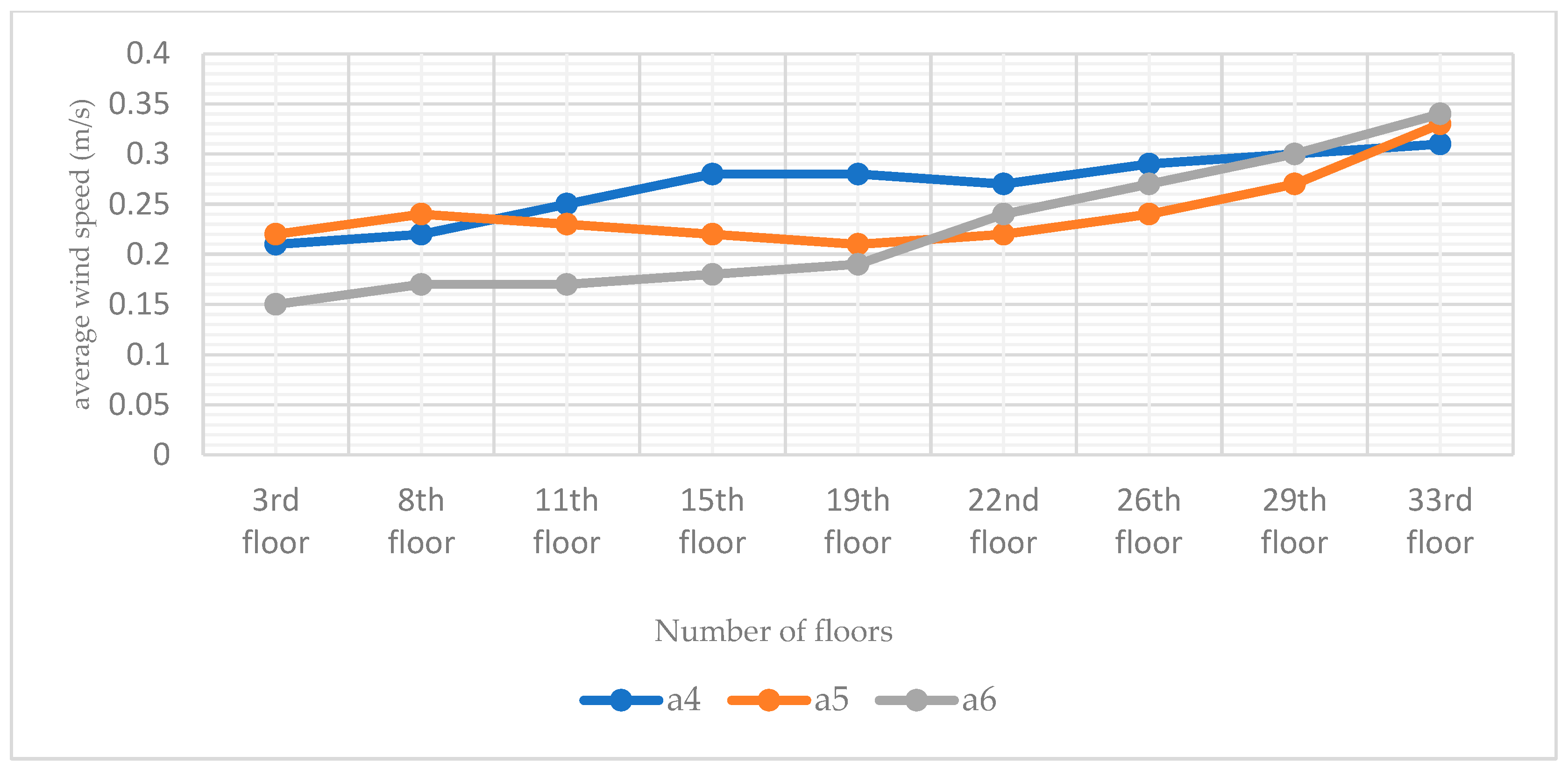
| Dual chamber | a4 | 0.21 | 0.22 | 0.25 | 0.28 | 0.28 | 0.27 | 0.29 | 0.30 | 0.31 | 0.10 |
| a5 | 0.22 | 0.24 | 0.23 | 0.22 | 0.21 | 0.22 | 0.24 | 0.27 | 0.33 | 0.11 | |
| a6 | 0.15 | 0.17 | 0.17 | 0.18 | 0.19 | 0.24 | 0.27 | 0.30 | 0.34 | 0.19 | |
| Model maximum wind speed difference | 0.11 | 0.10 | 0.10 | 0.12 | 0.10 | 0.09 | 0.10 | 0.04 | 0.06 | 0.15 | |
Disclaimer/Publisher’s Note: The statements, opinions and data contained in all publications are solely those of the individual author(s) and contributor(s) and not of MDPI and/or the editor(s). MDPI and/or the editor(s) disclaim responsibility for any injury to people or property resulting from any ideas, methods, instructions or products referred to in the content. |
© 2023 by the authors. Licensee MDPI, Basel, Switzerland. This article is an open access article distributed under the terms and conditions of the Creative Commons Attribution (CC BY) license (https://creativecommons.org/licenses/by/4.0/).
Share and Cite
Wei, Y.; Lin, Z.; Wang, Y.; Wang, X. Simulation and Optimization Study on the Ventilation Performance of High-Rise Buildings Inspired by the White Termite Mound Chamber Structure. Biomimetics 2023, 8, 607. https://doi.org/10.3390/biomimetics8080607
Wei Y, Lin Z, Wang Y, Wang X. Simulation and Optimization Study on the Ventilation Performance of High-Rise Buildings Inspired by the White Termite Mound Chamber Structure. Biomimetics. 2023; 8(8):607. https://doi.org/10.3390/biomimetics8080607
Chicago/Turabian StyleWei, Yangyang, Zhiying Lin, Yihan Wang, and Xinxia Wang. 2023. "Simulation and Optimization Study on the Ventilation Performance of High-Rise Buildings Inspired by the White Termite Mound Chamber Structure" Biomimetics 8, no. 8: 607. https://doi.org/10.3390/biomimetics8080607
APA StyleWei, Y., Lin, Z., Wang, Y., & Wang, X. (2023). Simulation and Optimization Study on the Ventilation Performance of High-Rise Buildings Inspired by the White Termite Mound Chamber Structure. Biomimetics, 8(8), 607. https://doi.org/10.3390/biomimetics8080607