Article

Effect of Gravity on the Scale of Compliant Shells

by
Victor Charpentier
* and
Sigrid Adriaenssens
Department of Civil and Environmental Engineering, Princeton University, Princeton, NJ 08544, USA
*
Author to whom correspondence should be addressed.
Biomimetics 2020, 5(1), 4; https://doi.org/10.3390/biomimetics5010004
Submission received: 3 November 2019 / Revised: 28 December 2019 / Accepted: 9 January 2020 / Published: 27 January 2020

Abstract

:
Thin shells are found across scales ranging from biological blood cells to engineered large-span roof structures. The engineering design of thin shells used as mechanisms has occasionally been inspired by biomimetic concept generators. The research goal of this paper is to establish the physical limits of scalability of shells. Sixty-four instances of shells across length scales have been organized into five categories: engineering stiff and compliant, plant compliant, avian egg stiff, and micro-scale compliant shells. Based on their thickness and characteristic dimensions, the mechanical behavior of these 64 shells can be characterized as 3D solids, thick or thin shells, or membranes. Two non-dimensional indicators, the Föppl–von Kármán number and a novel indicator, namely the gravity impact number, are adopted to establish the scalability limits of these five categories. The results show that these shells exhibit similar mechanical behavior across scales. As a result, micro-scale shell geometries found in biology, can be upscaled to engineered shell geometries. However, as the characteristic shell dimension increases, gravity (and its associated loading) becomes a hindrance to the adoption of thin shells as compliant mechanisms at the larger scales-the physical limit of compliance in the scaling of thin shells is found to be around 0.1 m.

1. Introduction

Thin shells, whether stiff or flexible, are curved solids with two large dimensions and a third one that is very small (thickness). In contrast to plates whose initial configuration is planar, shells are controlled by geometry and defined by their curvature. Shells built for stiffness are designed to maximize the material efficiency and reduce the overall weight-to-span ratio. By choosing an appropriate geometry for the given boundary conditions and given load case, a stiff shell experiences mostly membrane forces that can be resisted by using little material. The displacements resulting from the applied loads are practically nonexistent. In contrast, shells built for flexibility use geometry and inextensibility of materials to convert bending stresses into tuned, reversible large displacements. The use of shells as mechanisms is part of the broader, growing trend in compliant mechanisms to deform a large portion of a structure to produce movements (distributed compliance) [1,2,3,4,5,6] instead of lumped compliant hinges or common rigid body hinges.
However, when it comes to bio-inspiration, the question of scalability of natural structures becomes common. For instance, a closed shell, such as an avian egg, can rest on a plane without being damaged at a small scale. When scaled up, the shell’s self-weight, and thus the impact of gravity, increases. Under the same support conditions as the small-scale structure, the large upscaled shell could be subject to localized deformation such as buckling [7]. While this action of gravity is easily understood in this example of an egg-like shell, the question remains open to determine at which scale the action of gravity becomes too great for compliant shells to operate reliably. Shell structures span over 10 orders of magnitude across both biology and engineering. Shell mechanics are used to describe the large shape transitions of viruses [8], and of red blood cells [9], and are the mechanical system for some of the fastest repeatable plant movements [1]. Their flexibility allows the movement in engineered compliant structures such as hingeless joints [10], or active piezoelectric actuators [11]. All these flexible structures are elastically deformed, which makes them susceptible to undergo large stresses. However, similarly to their stiff counterparts, the geometry of compliant shells influences the magnitude of those stresses [12]. With advances in the modeling of large deformations [13,14], the use of shells as mechanisms is now made possible. While biologically compliant shells appear at the smallest of the 10 length scales cited above, the use of those structures in biology has started to inform the design of engineered mechanisms at larger scales. Examples of flexible shells observed in nature have inspired engineered scale adaptive structures [15,16,17,18] at the meter scale, but the question of whether such structures could be scaled up even further still remains open and drives this study. This succinct literature review shows that there is a clear gap of knowledge as to what the limiting scale of compliant shells is and what the defining parameter is that determines this scale.
The main hypothesis guiding this study is that the lack of large-scale compliant shells is due to the limiting effect of gravity-induced body forces on the shell’s movements. Therefore, the goal of this paper is to gain insight in the influence of gravity-induced forces on the ability of shells to perform as mechanisms through an order-of-magnitude approach. To achieve this goal, we are guided by the following four research tasks. First, we identify and catalogue the dimensions and mechanical characteristics of shell instances across 10 orders of magnitude of span. Second, we apply the non-dimensional Föppl–von Kármán number [19] to each of those shells to characterize the most likely deformation mode (i.e., bending or stretching). Third, in order to characterize the influence of gravity forces on a shell, we introduce a new non-dimensional number called the gravity impact number (Gi), which is the ratio of the elastogravity length scale [20,21] to the characteristic dimension of the shell. The elastogravity length scale determines the limit at which bending deformations due to gravity appear in the shell. Finally, using this newly introduced parameter, we measure the scale at which compliant shells become highly susceptible to gravity induced deformations.
This paper presents an order-of-magnitude study on the behavior of shells. The main parameter used to describe the scale of the shells is their characteristic dimension (R), also referred to as span in engineering practice. The thickness (H) of the shells is related to R by the definition of thin and thick shells. The definition of a shell comes from the ratio of span to thickness. This ratio is found between 8 and 20 for thick shells and between 20 and 100,000 for thin shells [22]. Other geometric parameters can be used to measure the order-of-magnitude of the size. The radius of curvature or the length of a geodesic line could also be used in the context of this study. However, two reasons led to the choice of the span as controlling scale parameter: both the radii of curvature and the length of geodesic line are, in most cases, of the same order of magnitude as the span of shell, and the characteristic dimension is much more accessible in scientific literature than the two other parameters.
The main contributions of the paper are (1) the cataloguing of stiff and compliant shells across scales of 10 orders of magnitude, (2) the use the Föppl–von Kármán number to characterize the mechanical behavior of those shells, (3) the introduction of the gravity impact number to describe the scale at which the pull of gravity becomes a dominant factor in the analysis of shells, and (4) the determination that this scale is ~0.1 m.
In Section 2, the typologies of shells are introduced. In addition, the assumptions and calculation methodologies for each non-dimensional number are presented. In Section 3 of the paper, the respective values of the Föppl–von Kármán number and the gravity impact number are reported for each category of shells. In Section 4, the results are discussed, and further analysis is provided to understand the trends in data from Section 3. In Section 5, conclusions are drawn from the paper and recommendations for the use of shells as mechanisms are provided. The complete list of shells used in the study is documented in the appendices. In addition to providing the list of all the structures included, the appendices also list the principal dimensions as well as the material properties of each one of the shell instances.

2. Methodology

In this section, the typologies of shells featured in the study are presented and the assumptions for the non-dimensional numbers used to characterize their mechanical behavior are detailed. The comparison of the shells is done using two non-dimensional numbers: the Föppl–von Kármán number and the gravity impact number. In this section, the hypotheses for the use of each number is presented. The Föppl–von Kármán number, γFvK, describes the type of deformation that dominates the mechanical behavior of a thin shell. The gravity impact number (Gi) characterizes the influence of the gravitational force on the shell. The thin shells are considered isotropic elastic in this study.

2.1. Sample of Fixed and Compliant Shells

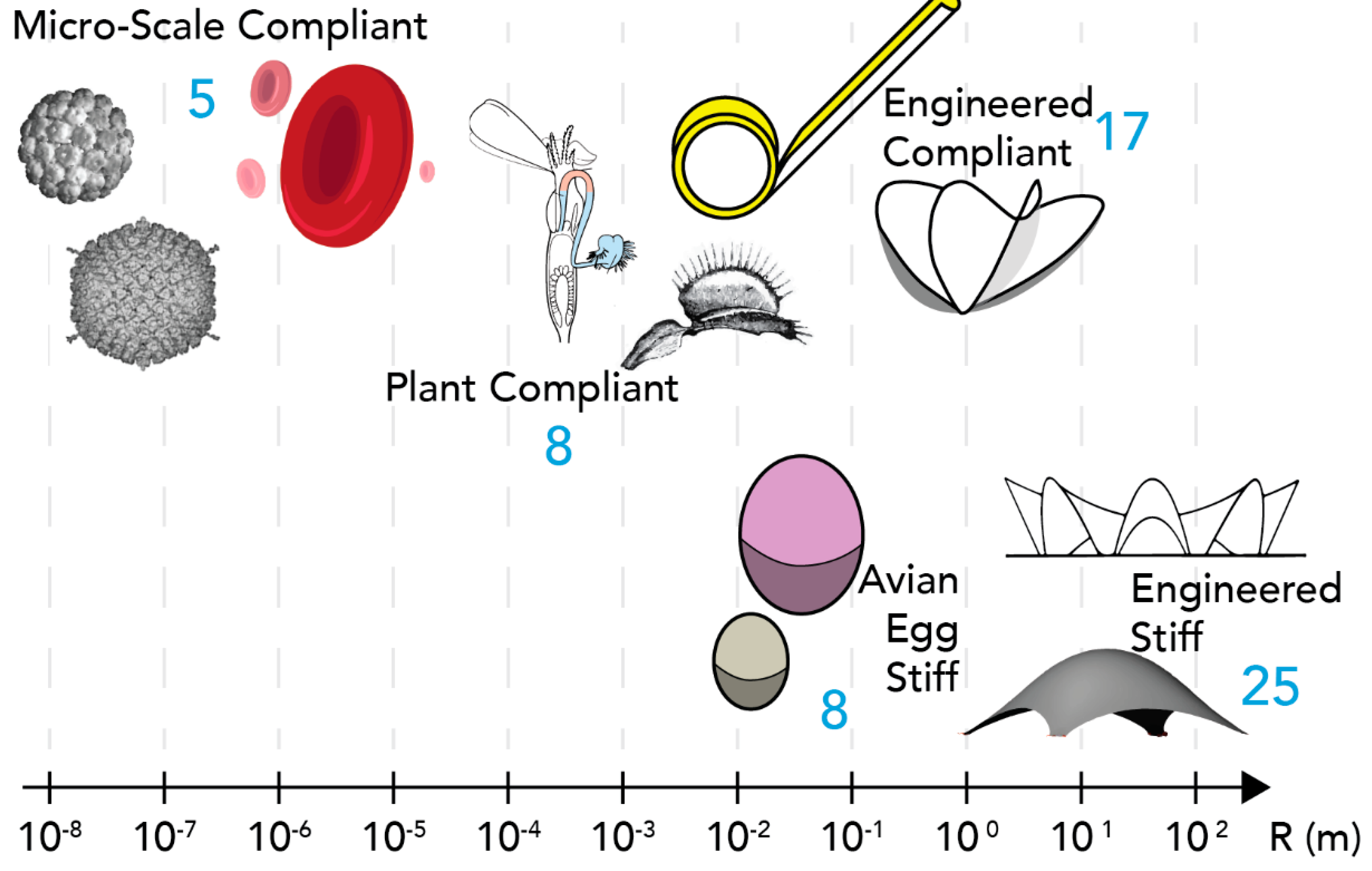
Across 10 orders of magnitude, 64 shell instances are selected from an extensive literature review that reported their mechanical behavior (Figure 1). The dimensions and references to all 64 shells are recorded in the section supplemental material (Appendix A). This study excluded several large scale compliant shells [23] for space applications since the forces due to gravity is reduced around earth’s orbit. The five categories of shells are:
  • Engineered stiff shells [15]. 25 large scale reinforced concrete (high Young’s modulus) thin shells used in buildings and architecture, their shape is fixed and can carry external applied loads. Their characteristic dimension (R) is in the [ 6 × 10 °   m ;   8 × 10 1   m ] range, while their thickness H is in the [ 5 × 10 2   m ; 4 × 10 1   m ] range
  • Engineered compliant shells [12,16,17,18,24,25,26,27,28,29,30,31,32]. 18 shells designed for use as mechanisms, they are very flexible. Materials are varied but all have high Young’s modulii. R in [ 2 × 10 2   m ; 8 × 10 0   m ] and H   in   [ 1.2 × 10 4   m ; 9 × 10 4   m ]
  • Plant compliant shells [33,34,35]. 8 plant structures that can be described as thin shells and exhibit fast and repeated motions. The material is a living tissue of low Young’s modulus ( ~ 10 6   N / m 2 ). R in [ 1.5 × 10 4   m ; 1 × 10 2   m ] and H   in   [ 3 × 10 5   m ; 4 × 10 4   m ]
  • Avian egg stiff shells [36,37,38]. 8 stiff bird eggshells. The geometry is rigid and the material is carbon silicate of various mechanical properties detailed in [38]. R in [ 3 × 10 2   m ; 1.55 × 10 1   m ] and H   in   [ 2.2 × 10 4   m ; 2.55 × 10 3   m ]
  • Micro-scale compliant shells [8,19,39,40,41,42]. 5 types of shells from red blood cells to virus. They have been described mechanically as a shell and deform significantly in operation. They are highly flexible. R in [ 2 × 10 8   m ; 5 × 10 4   m ] and H   in   [ 2 × 10 9   m ; 1 × 10 6   m ]

2.2. Quantification of Bending versus Stretching Deformation

Shells used as mechanisms rely on the property of very thin curved bodies to deform without distortion of their surface metric, i.e., without stretching. This type of deformation known as inextensional bending, or isometric bending [7,43,44] minimizes the strain energy because it does not stretch the material. The minimization of elastic strain energy is the core energy objective of compliant mechanisms. Smooth deformations without stretching are geometrically possible if the shell has free edges (and only exceptionally if the surface is closed) [44]. For thin shells, the strain energy density W includes stretching and bending. Bending in this context includes both bending and torsion. The stretching energy density W s t r e t c h i n g is proportional to the shell’s thickness H, while the bending energy density W b e n d i n g is proportional to the cube of the shell’s thickness H3 [45]. For equal energy levels, bending deformations can be much larger than stretching deformations. Therefore, bending allows the shell to deform with less impact on the overall elastic strain energy compared to stretching. Since isotropic thin shells are considered, the general form for the surface strain energy density W is given by the equation [45]
W = W s t r e c h i n g + W b e n d i n g
with the stretching and bending energy densities defined as
W s t r e t c h i n g ~ Y H ( 1 ν 2 )   ϵ 2
W b e n d i n g   ~   Y H 3 12 ( 1 ν 2 )   κ 2  
where  is Young’s modulus, ν is Poisson’s ratio, ϵ is average in-plane strain, and κ is average variation of shell curvature.
In order to measure and compare the tendency of bending-only-deformations in thin shells, the dimensionless γFvK, number [19] is used. This number measures the ratio of stretching to bending strain energy densities and is given by
γ F v K = Y H R 2 D
with R the characteristic length of the thin shell (in general of same order of magnitude as the principal curvature radii [46]) and D the bending modulus (also called the flexural stiffness),
D = Y H 3 12 ( 1 ν 2 )
such that after simplifications the γ F v K number becomes proportional to R 2 / H 2
γ F v K = Y H R 2 D = 12 ( 1 ν 2 ) R 2 H 2
The γFvK number predicts the type of deformation a shell will experience. Very large values of γFvK indicate that the shell behaves similarly to a membrane. Such shells accommodate elastic compressive strain by wrinkling and if very thin, crumpling [47]. The shells with high values of γFvK exhibit large bending and low stretching. Lower values of γFvK correspond to thicker shells that have a high bending stiffness. Such shells have both bending and stretching deformations and require large applied loading to be deformed. The ideal behavior for a thin shell used as a mechanism is characterized by a small actuation force that results in both bending deformations and preservation of the smoothness of the surface (i.e., no crumpling or wrinkling). This force can only be made small if it activates is low stiffness deformation mode of the shell [16]. This ideal behavior occurs if the shell is stiff enough to have a bending stiffness that preserve the continuity of the material under loading and flexible enough to allow large elastic out-of-plane deformation. The instances of compliant shells selected in this study fit this description, their γFvK values can be considered as characteristic for compliant shells. The range of γFvK values in this study is 103 to 108 (see Section 3). However, physically, the maximum value of the γFvK number is γFvK 10 14 . This value does not occur for shells since it describes the behavior of a 200 μ m square sheet of graphene [48]. Graphene is one-atom thick membrane with high in plane Young’s modulus ( Y = 500   GPa ). It has no bending stiffness and therefore is not relevant for this study. Since there is nothing thinner than a single layer of atoms, graphene constitutes the limit of physically feasible structures.

2.3. Influence of Gravity Body Forces on Shells

To establish the scale limits for compliant shell, the force resulting from gravity needs to be considered as a limiting factor for their movement. A non-dimensional number, called the gravity impact, Gi, number is introduced in this paper to quantify the gravitational impact on a shell’s behavior. The Gi number is defined as the ratio of the elastogravity length scale l e g [20,21] to the characteristic dimension of the shell R .
The gravitational potential energy density ( W g r a v i t y ) scales as
W g r a v i t y   ~   g ρ δ 2
With g being the acceleration of gravity, ρ being the volumetric mass density of the material, and δ being the deformation due to gravity. From a dimensional point of view, the variation of average curvature κ can be expressed as a function of δ as κ   ~   δ / R 2 . The gravitational pull causes the shell to bend when the bending energy and the gravitational potential energy are of the same order of magnitude, i.e., W b e n d i n g W g r a v i t y . This situation occurs for R   ~   l e g . Equating Equations (3) and (6) yields Equation (7)
l e g   ~   ( D g ρ ) 1 / 4
Therefore, the nondimensional Gi number for a thin shell is
G i = l e g R = ( D g ρ R 4 ) 1 / 4
Therefore, if Gi is larger than one, the characteristic dimension of a thin shell is smaller than l e g : the gravity effect on the behavior of the compliant shell can be ignored. The nondimensional Gi number determines the tendency of a compliant shell to be affected by the gravitational pull as a function of its scale. Values of Gi lower than unity indicate that gravitational forces exert a large influence on the shell’s mechanical behavior. In contrast, Gi values over one indicate gravitational forces are not of key importance in the deformation. The gravitational pull increases as the characteristic dimension of the shell increases. Compliant thin shells of large dimensions are rare but there are some examples of such shells where the characteristic dimension is in the order of magnitude of 10 0 m or below. Therefore, the Gi number is used in this study to detect and highlight the scaling limits of compliant thin shell.

3. Results

3.1. Föppl–von Kármán Number Values Across Scales

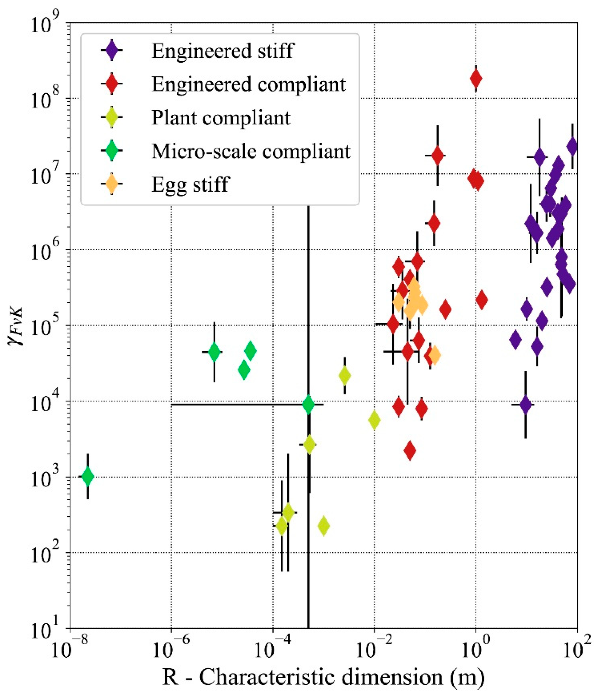
The 64 thin shells included in this study are plotted by thickness H and characteristic dimension R in Figure 2. γFvK describes whether stretching and/or bending deformations control the deformed state of the shell. Being a non-dimensional number, it applies to any shell, independent of the magnitude of its characteristic dimension R. The average values of γFvK shown in Table 1 are within the range 10 3 to 10 8 . To understand the variability observed in Table 1, we need to define precisely the subcategories of solids that appear on Figure 2. In this study the ratio R/H for a thin shell is adopted from [22] and given by
20   R H 100 , 000
In comparison, thick shells have a larger R/H ratio also defined in [22] and given by
8   R H t h i c k S h e l l   20
All stiff shells and compliant engineered shells in this study fall within the range of R/H ratios defined in Equations (9) and (10), respectively. The 3D solids with R/H values less than 8 are rigid bodies that cannot be described as having two spatial dimensions much larger than the third one. Therefore, they are not considered shells and Equations (3) and (9) do not apply to them, those structures appear on the left-hand side of Figure 2. In contrast, when the R/H ratio is larger than 100,000, shells become extremely thin. They lose any bending stiffness and can only experience in-plane forces (stretching). They can no longer be called shells and are referred to as membranes. (right-hand side of Figure 2). The average values of γFvK in Table 1 indicate a mechanical behavior dominated by bending deformation for both stiff and compliant shells. Overall, since thin shells have R/H ratios in the range of [ 20 ; 100 , 000 ], their γFvK values are bounded by lower ( γ F v K   ~ 10 3 ) and upper bounds ( γ F v K   ~ 10 8 ). This observation indicates that thin shells—whether they are engineered stiff or compliant, plant compliant, micro scale compliant, or egg stiff—exhibit similar mechanical behavior, which is dominated by bending deformations across scales.
Of the 64 thin shell typologies recorded in this study, 95% have values of γFvK between 10 3 and 10 8 , as shown in Figure 2 and Figure 3. In the sample of shells selected for this study, only some of the compliant plant shells present values of γFvK lower than 103 (Figure 3). Those same instances are on the border of the range of R/H ratios that characterizes shell structures (Figure 2). The main simplifying hypothesis of this study is that the material of the structures selected is isotropic elastic. In the case of the plant structures, the complex nature of the plant material (referred to as plant tissue) requires further justification for being included in this study. Biological tissues that constitute the moving organs of the plants instances included in the study are a hierarchized, non-homogeneous material [1]. As a living material, not all parts of tissue perform structural functions [49]. The structural layers of the tissue are thinner than the overall tissue [1] therefore in the cases presented in the study, the ratio R/H of the plants despite being loaer than other examples of shells are still accepted.
A specific example of this behavioral similarity can be found in the Algeciras Market Hall’s reinforced concrete shell [15] and red blood cells. Both of those structures have similar Föppl–von Kármán number γ F v K ~ 10 5 , which indicates a similar tendency to bending deformation over stretching deformations for both structures. This high γFvK indicates a high in-plane stiffness compared to the out-of-plane bending stiffness. Therefore, bending deformations are more likely to occur than stretching for both structures. In theory, the structure of the Algerciras Market hall should be able to undergo similar reversible large shape changes as red blood cells. The market hall is a stiff concrete shell considered a model of shell design [15]. While in pure mechanical terms the concrete structure could be used as a compliant shell, the actual Algerciras Market Hall is dominated by dead-load’s vertical action and subjected to edge boundary conditions.

3.2. Impact of Gravity on Shell Mechanical Behavior Across Scales

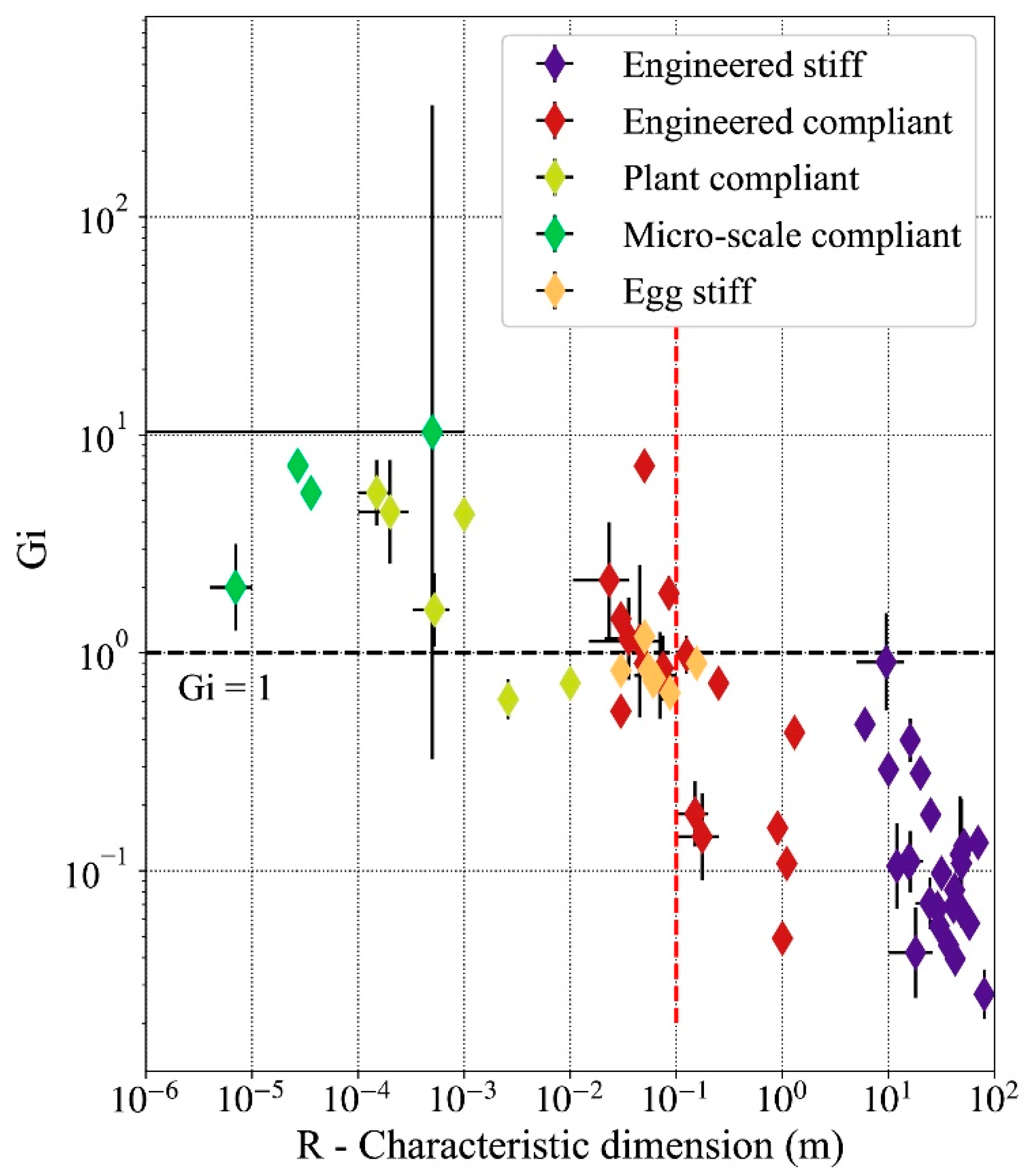
The thickness and the characteristic dimension of the shells are related by the ratio R/H discussed in Section 3.1. Therefore, the characteristic dimension will be taken as the reference indicator of a shell’s geometry going forward. The relationship between the Gi number and geometry is shown in Figure 4. The Figure shows that stiff engineered thin shells have the largest values of Gi, while micro-scale compliant shells have the lowest values.
In accordance with Equation (8), the gravitational force is larger (in magnitude) as the scale of the shell increases. This is appears in Figure 4 with thin shell of larger characteristic dimensions having low values of Gi such as for example façade shading shells [16,17,28]. Shells with a characteristic dimension R lower than 0.1 m tend to have G i > 1 . For these shells, large deformation caused by gravity does not occur. The relationship G i > 1 only occurs for one-third of compliant engineered shells, which means that most engineered shells must deal with the influence of gravity. All studied stiff engineered shells have an elastogravity length scale shorter than their characteristic dimension R. This observation indicates that for these shells the gravitational forces due to self-weight dominate the elastic bending resistance. The average value of Gi is found to be 0.109 for stiff engineered shells, 0.610 for compliant engineered shells, 2.465 for plant compliant shells, 0.822 for the egg shells, and 7.739 for the micro-scale compliant shells.
In addition, shells with a characteristic dimension larger than 0.1 m consistently have values of Gi lower than one (Figure 4). This scale is displayed by the red dotted line on Figure 4. No structure to the right of this line has a gravity impact number larger than one.
There is not a clear division defined by Gi between compliant and stiff thin shells. Some engineered compliant thin shells are used as mechanisms but have a lower Gi value than the one of stiff shells. A high value of Gi can also indicate a shell with large thickness H with a corresponding low γFvK value. The plant compliant shells have relatively high Gi values, which means the shell does not deform under the influence of gravity. The larger plant compliant shells have Gi values comparable to those of stiff engineered shells, indicating that the shell would be susceptible to the influence of gravity. However, for the living tissues, the ratio of volumetric mass density ρ to Young’s modulus Y is ~ 10 3 times lower than that for engineered shells, which explains some of the low values of Gi despite the small characteristic dimensions R.

4. Discussion

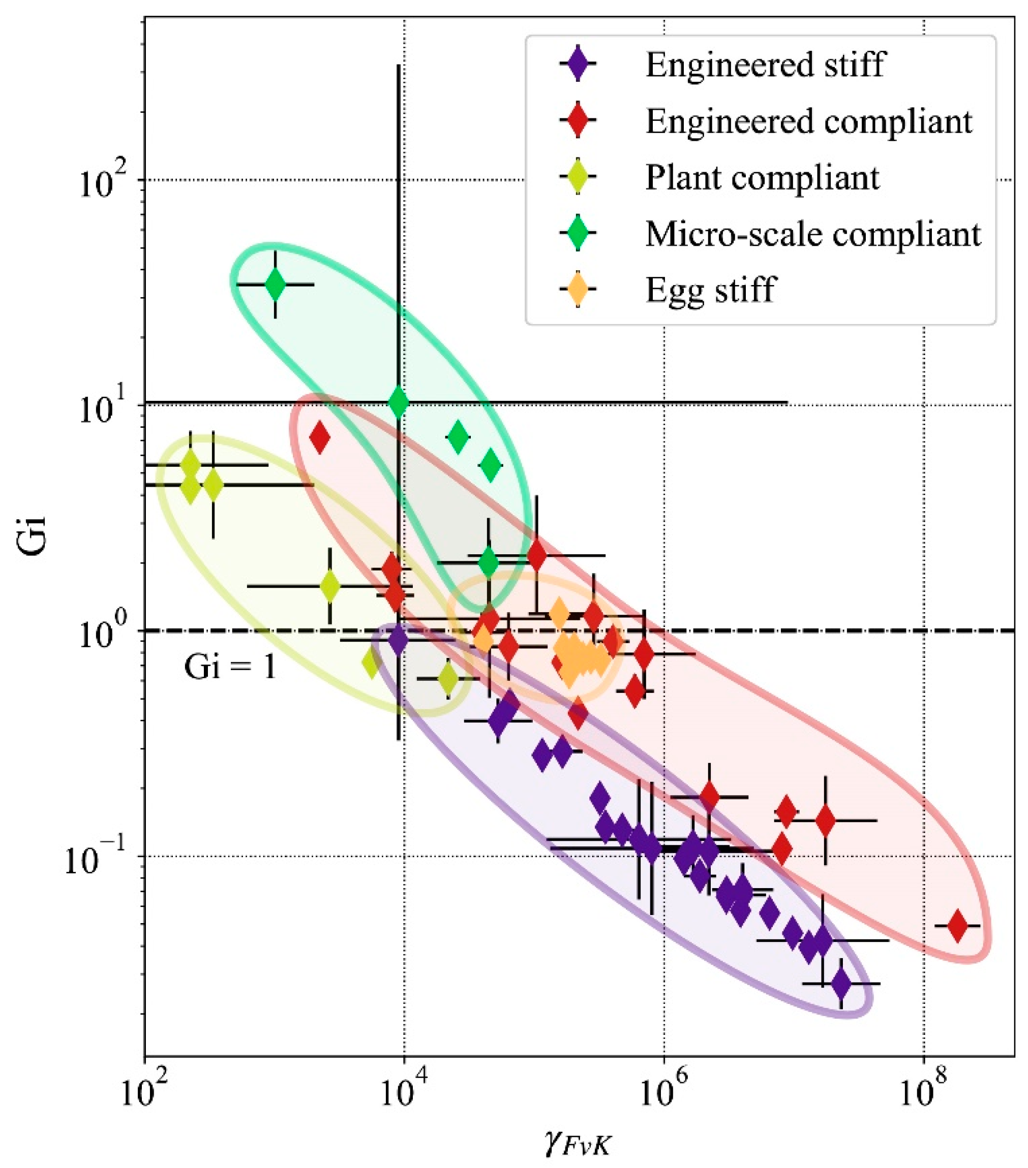
Thin shells have a tendency to deform in bending rather than in stretching across scales. Most thin shells studied have values of the Föppl–von Kármán number γFvK between 10 3 and 10 8 . This non-dimensional number is significant because it unifies the behavior of shells across scales. This outcome is in line with the bio-inspiration approach that distills geometries of a plant or micro-scale shell and scales them up for engineering applications [1,16]. As long as the ratio of characteristic dimension R over thickness H is kept high, the mechanical behavior of the compliant shell is similar at the large engineered scale and the observed biological scale. The five categories of thin shells presented in this paper (i.e., engineered stiff, engineered compliant, plant compliant, micro-scale compliant, and egg stiff) have instances with γ F v K in the range of 10 4 to 10 5 . This observation exemplifies the that shells used as mechanisms appear at all scales Figure 5. Thin shell can have a similar mechanical behavior dominated by bending deformation across 10 orders of magnitude of their characteristic dimension R.
Compliant shells found in plants are made from living tissues, a multileveled arrangement of cells. In this material, the transport of water generated by electro-chemical reactions increases the water pressure in select part of the tissue, thus generating actuation [1]. Plant tissues are a self-actuating material. As discussed in Section 3.1, despite being classified as thick shell or almost 3D solids, plant mechanisms still feature in this study due to the properties of the thin structural layers of the motile plant organs being the main structural component of the mechanisms. For plants, the elastogravity length leg scale is large compared to their characteristic dimension R. In the genus Stylidium for example, the characteristic dimension R of the mechanism is 4.3 times larger than the elastogravity length scale leg, which indicates that the plant’s movement is quasi unaffected by gravity. In general, plants can move without having the deformed geometry being influenced too much by gravity. The orientation of their mobile parts with respect to the gravitational pull does not obstruct or favor the shell movement.
Large-span stiff engineered shells use engineered materials with high Young’s moduli Y and are designed to have a fixed shape that minimizes bending stresses and can thus be made very thin. In contrast, compliant shells must repeat elastic deformations reliably at a low actuating cost. The scale at which shells’ compliant deformations start to be affected by gravity is R   ~   0.1   m . Below that scale, compliant shells operate independent of gravity. For instance, the adaptive air inlet for aeronautic applications described in [12] must be able to function under any orientation of the airplane. In contrast, a compliant shell for adaptive shading of buildings does not have the same constraints as it operates in a position aligned with gravity’s vertical orientation and can therefore be up scaled to larger sizes [16,17,18].

5. Conclusions

When upscaling stiff and compliant shells from small scale biology to large scale engineered applications, the pull of gravity needs to be accounted for. The first contribution of this paper is the identification and logging of the dimensions and mechanical characteristics of 64 shell instances across 10 orders of magnitude of span. The shells listed are drawn from micro-biology, plant biology, animal biology, and engineering. Using the non-dimensional Föppl–von Kármán number, bending was shown to be more likely to occur than stretching as the dominating deformation mode for shells across all scales. Stiff engineered shells are shaped so that this tendency is neutralized but compliant shells take advantage of it to deform (second contribution). In order to characterize the influence of gravity on those compliant shells across scales, Gi was introduced in this paper. This non dimensional number determines at what scale gravity becomes relevant in the study of shell mechanics (third contribution). In particular, Gi is defined as the ratio of the elastogravity length scale to the characteristic dimension of the shell and measures whether the scale at which bending deformation due to self-weight appears in a shell is larger or smaller than the actual size of the shell. The fourth contribution is the identification of the scale at which shells become influenced by gravity. Based on the characteristics of the 64 listed shells and using Gi, it is shown that the effect of gravity on compliant shells sets on at a scale of ~0.1 m. Compliant shells at larger scales (R > 0.1 m) are prone to self-weight deformation under gravity load. This deformation can hinder their function depending on the nature of the application. A mechanism based on compliant shells that needs to perform reliably under varying orientation (e.g., airplane wing) will not be able to be scaled to large scales. However, if the application does not demand a change of orientation, the structure can be scaled up providing that the orientation of gravity is taken into account in the design of the compliant shell.
The following strategies can be used for compliant thin shells to circumvent G i < 1 while having a high γFvK.
  • The mobile part of the shell is designed to possess enough stiffness to be cantilevered. In most compliant shell building shading systems [16,17,18], this stiffness is provided by curvature and built-up stresses.
  • The mechanism is oriented to limit the increase of cantilevered length during the movement. For example, the façade of the Yoesu Expo 2012 Pavilion was designed so that the flexible shell elements do not create large overhangs during the out-of-plane buckling deformation [28]. The longest elements are 8 m tall and still able to be elastically deformed repeatedly.
  • The bending deformation of thin shells can be predicted by studying the possible isometric deformation of their geometry [44]. The deformation of very curved surfaces could lead to mechanisms being able to withstand gravity better due to their doubly-curved geometry [26].
  • The final strategy to create large-scale compliant thin shells is to operate in outer space. The behavior of shells is similar across scales. Bending deformation modes dominate stretching modes when shells are thin enough. Being able to remove gravity forces could lead to large shells being used as compliant mechanisms.
Determining the limits of scalability of shell used as mechanisms will allow designers to expand the use of those structures, using the geometry of small-scale thin shells for inspiration in engineered applications. To support this development, further work should be carried on form finding applied to large displacements of shells. Throughout this paper, parallels have been made between the design of stiff shells and the design of compliant shells. There is a well-established field of structural research dedicated to the search for optimal forms for stiff shells. The development of tools for finding appropriate and custom flexible shell geometries could lead to structural designers departing from a pure mimetic based approach that upscales geometries to a generative approach that is able to generate appropriate flexible shapes for kinematic problems.
Author Contributions

Conceptualization, V.C. and S.A.; Methodology, V.C.; Formal analysis, V.C.; Investigation, V.C.; Data curation, V.C.; Writing—original draft preparation, V.C.; Writing—review and editing, V.C. and S.A.; Visualization, V.C.; Supervision, S.A. All authors have read and agreed to the published version of the manuscript.

Funding

This research received no external funding.

Conflicts of Interest

The authors declare no conflict of interest. The funders had no role in the design of the study; in the collection, analyses, or interpretation of data; in the writing of the manuscript, or in the decision to publish the results.

Abbreviations

RCharacteristic dimension of shells
HThickness
YYoung’s Modulus
γ F v K Föppl–von Kármán number
GiGravity impact number
W Strain energy density
W s t r e t c h i n g Stretching strain energy density
W b e n d i n g Bending strain energy density
ν Poisson’s ratio
ϵ Average in-plane strain
κ Average variation of shell curvature
l e g Elastogravity length scale
δ Deformation due to gravity
g Acceleration due to gravity
ρ Volumetric mass density
D Bending modulus (or flexural stiffness)

Appendix A. Sample of Cross-Scale Stiff and Compliant Thin Shells Instances

This appendix references the thin shells included in the study. Large scale thin shell structures found in literature are mostly stiff. In contrast, compliant thin shell structures present a characteristic dimension in the order-of-magnitude 10 0 m or below.

Appendix A.1. Stiff Engineered Thin Shells

Most structures considered in this section were constructed with concrete or reinforced concrete. This material gives a good order of magnitude for the material properties used in large scale engineered thin shells. The material properties needed for the calculation of the γ F v K and the Gi numbers are Young’s modulus, volumetric mass density and Poisson’s Ratio. Those values are taken from the Eurocode 2 [50] and presented in Table A1. The values reflect commonly used values of concrete in design. They are indicative of order-of-magnitude for the parameters considered.
Table A1. Material properties used in the calculation of γ F v K and Gi numbers for the engineered thin shells.
Material PropertyValue
Volumetric mass density (kg·m−3)2500
Modulus of Elasticity (GPa)35
Poisson’s ratio0.20
The structures selected for this study have been built throughout the 20th and 21st centuries. They have been extensively described in [15]. Their dimensions are reported in Table A2.
Table A2. Dimensions of large scale engineered thin shells included in the study. The structures are described in [15].
IdName/LocationDesignerRef.Span (m)Thickness (m)
Min.Max.Avg.Min.Max.Avg.
1AichtalBalz, Isler[15]42.042.042.00.0900.1200.105
2AlgecirasSanchew Arcas, Torroja[15]47.547.547.50.0890.4570.273
3BacardiCandela[15]36.836.836.80.0400.0400.040
4BundesgartenschauSBP[15]10.026.018.00.0120.0150.014
5Lomas De CuernavacaCandela[15]18.031.024.50.0400.0400.040
6MilagrosaCandela[15]11.021.016.00.0400.0400.040
7San Jose ObreroCandela[15]30.030.030.00.0400.0400.040
8Cosmic RaysCandela[15]12.012.012.00.0150.0500.033
9DeitingenIsler[15]31.631.631.60.0900.0900.090
10FloreliteIsler[15]41.041.041.00.0800.0800.080
11GiessHaussHenschel[15]16.016.016.00.1750.3200.248
12GringrinSasaki[15]70.070.070.00.4000.4000.400
13HeimbergIsler[15]48.548.548.50.0900.1000.095
14HippoSBP[15]29.029.029.00.0400.0600.050
15HyperthreadsZaha Hadid[15]6.06.06.00.0800.0800.080
16JeronimoDe Castillo, de Boitaca[15]10.010.010.00.0700.1000.085
17KakamigaraIto, Sasaki[15]20.020.020.00.2000.2000.200
18KitagataIsozaki, Sasaki[15]25.025.025.00.1500.1500.150
19KresgeSaarinen, B&H, A&W[15]48.848.848.80.0750.4550.265
20Los ManantialesCandela[15]42.542.542.50.0400.0400.040
21MapungubweRich, Ochsendorf, Ramage[15]5.014.09.50.3000.3000.300
22RolexSANAA, Sasaki[15]80.080.080.00.0400.0800.060
23Rio WarehouseCandela[15]15.315.315.30.0400.0400.040
24SicliHiberer, Isler[15]58.058.058.00.1000.1000.100
25TeshimaNishizawa, Sasaki[15]43.060.051.50.2500.2500.250

Appendix A.2. Compliant Engineered Thin Shells

More than any other type of shell structures in this study, engineered compliant thin shells have very different material properties from one to the other. Table A3 and Table A4 present those material properties and the characteristic dimensions.
Table A3. Material properties of the compliant engineered thin shells included in the study.
IdDescriptionRef.MaterialPoisson’s RatioYoung’s Modulus (N/m−2)Volumetric Mass Density (kg/m−3)
1Aldrovanda Half Sphere[16]CFRP0.37.60 × 10101800
2Snap Curved Helicoid[24]Polycaprolactone0.43.53 × 1081145
3Snap Curved Cylinder[24]PET0.45.00 × 1091380
4Flectofin[18]GFRP0.42.50 × 10101800
5Flectofold[17]GFRP0.41.15 × 10101100
6Gravity Compliant Shell[26]PETG0.42.35 × 1091300
7Multistable-Corrugated Shells[27]copper–beryllium0.31.31 × 10118950
8Multistable Inlet[12]CFRP0.37.60 × 10101800
9Yoesu One Ocean[28]GFRP0.42.50 × 10101800
10Scoliosis Brace Helix[29]CFRP0.37.60 × 10101800
11Scoliosis Brace Cantilever[29]Polycarbonate0.42.90 × 1091270
12Tape Spring [31]Steel0.32.10 × 10117800
13Stiffness Study Shell 1[32]Acrylic0.43.20 × 1091180
14Stiffness Study Shell 2[32]PETG0.42.06 × 1091270
15Antenna Tape Spring[30]CFRP0.33.56 × 10101440
16Collapsible Booms[25]CFRP0.37.60 × 10101800
17Deformable Mirrors[51]CFRP0.37.60 × 10101800
Table A4. Dimensions of the compliant engineered thin shells included in the study
IdDescriptionRef.Span (m)Thickness (m)
Min.Max.Avg.Min.Max.Avg.
1Aldrovanda Half Sphere[16]0.8001.0000.9005.00 × 10−48.00 × 10−46.50 × 10−4
2Snap Curved Helicoid[24]0.0250.0350.0301.00 × 10−3 1.00 × 10−31.00 × 10−3
3Snap Curved Cylinder[24]0.0250.0350.0301.20 × 10−41.20 × 10−41.20 × 10−4
4Flectofin[18]0.2500.2500.2502.00 × 10−32.00 × 10−32.00 × 10−3
5Flectofold[17]1.1001.1001.1001.25 × 10−31.25 × 10−31.25 × 10−3
6Gravity Compliant Shell[26]0.0500.1000.0759.00 × 10−49.00 × 10−49.00 × 10−4
7Multistable-Corrugated Shells[27]0.1000.2500.1751.25 × 10−41.25 × 10−41.25 × 10−4
8Multistable Inlet[12]0.0400.1000.0702.50 × 10−42.50 × 10−42.50 × 10−4
9Yoesu One Ocean[28]1.3008.0004.6509.00 × 10−39.00 × 10−39.00 × 10−3
10Scoliosis Brace Helix[29]0.0500.0500.0503.50 × 10−33.50 × 10−33.50 × 10−3
11Scoliosis Brace Cantilever[29]0.0700.1000.0853.00 × 10−33.00 × 10−33.00 × 10−3
12Tape Spring [31]0.0210.0500.0362.00 × 10−42.00 × 10−42.00 × 10−4
13Stiffness Study Shell 1[32]0.1000.1500.1252.00 × 10−32.00 × 10−32.00 × 10−3
14Stiffness Study Shell 2[32]0.0150.0750.0455.00 × 10−45.00 × 10−45.00 × 10−4
15Antenna Tape Spring[30]0.0500.0500.0502.25 × 10−43.00 × 10−42.63 × 10−4
16Collapsible Booms[25]0.0110.0360.0232.00 × 10−42.00 × 10−42.00 × 10−4
17Deformable Mirrors[51]1.0001.0001.0002.00 × 10−43.00 × 10−42.50 × 10−4

Appendix A.3. Compliant Plant Thin Shells

The material properties of plant mechanisms are presented in Table A5. Their characteristic dimensions are presented in Table A6. In plants, parenchyma cells are alive and constitute the bulk of tissue in the thin shell [49].
Table A5. Material properties used in the calculation of γ F v K and Gi numbers for the compliant plant thin shells [34].
Material PropertyValue
Volumetric mass density (kg·m−3)1300
Modulus of Elasticity (MPa)5
Poisson’s ratio0.5
Table A6. Dimensions of the compliant plant thin shells included in the study.
idNameRefSpan (m)Thickness (m)
Min.Max.Avg.Min.Max.Avg.
1Stylidium crossocephalum[33]1.00 × 10−31.00 × 10−31.00 × 10−35.00 × 10−45.00 × 10−45.00 × 10−4
2Stylidium graminifolium[33]1.00 × 10−31.00 × 10−31.00 × 10−35.00 × 10−45.00 × 10−45.00 × 10−4
3Stylidium piliferum[33]1.00 × 10−31.00 × 10−31.00 × 10−35.00 × 10−45.00 × 10−45.00 × 10−4
4Aldrovanda vesiculosa[34]2.60 × 10−32.60 × 10−32.60 × 10−34.00 × 10−57.00 × 10−55.50 × 10−5
5Dionea muscipula[34]1.00 × 10−21.00 × 10−21.00 × 10−24.00 × 10−44.00 × 10−44.00 × 10−4
6Utricularia Sp.[35]1.00 × 10−42.00 × 10−41.50 × 10−42.00 × 10−54.00 × 10−53.00 × 10−5
7Utricularia vulgaris[35]1.00 × 10−43.00 × 10−42.00 × 10−42.00 × 10−54.00 × 10−53.00 × 10−5
8Utricularia australis[35]3.30 × 10−47.20 × 10−45.25 × 10−42.00 × 10−54.00 × 10−53.00 × 10−5

Appendix A.4. Compliant Micro-Scale Thin Shells

The material properties of micro-scale compliant shells are presented in Table A7. Their characteristic dimensions are presented in Table A8.
Table A7. Material properties of the compliant micro-scale thin shells included in the study.
IdDescriptionRef.Poisson’s RatioYoung’s Modulus (N/m−2Volumetric Mass Density (kg/m−3)
1Red Blood Cell[40]0.53.10 × 1061000
2Artificial Capsules[19,39]0.51.00 × 1091000
3Virus[8,19]0.53.10 × 1061000
4Vesicle 1[41]0.51.00 × 1091000
5Vesicle 2[41]0.51.00 × 1091000
Table A8. Dimensions of the compliant micro-scale thin shells included in the study.
IdDescriptionRef.Span (m)Thickness (m)
Min.Max.Avg.Min.Max.Avg.
1Red Blood Cell[40]4.00 × 10−61.00 × 10-57.00 × 10−69.00 × 10−89.00 × 10−89.00 × 10−8
2Artificial Capsules[19,39]1.00 × 10−61.00 × 10−35.01 × 10−41.00 × 10−61.00 × 10−61.00 × 10−6
3Viruses[8,19]1.50 × 10−83.00 × 10−82.25 × 10−82.00 × 10−92.00 × 10−92.00 × 10−9
4Vesicle 1[41]2.40 × 10−53.00 × 10−52.70 × 10−55.00 × 10−75.00 × 10−75.00 × 10−7
5Vesicle 2[41]3.20 × 10−54.00 × 10−53.60 × 10−55.00 × 10−75.00 × 10−75.00 × 10−7

Appendix A.5. Stiff Eggshells

The material properties of micro-scale compliant shells are presented in Table A9. Their characteristic dimensions are presented in Table A10.
Table A9. Material properties of the avian egg thin shells.
IdDescriptionRefPoisson’s RatioYoung’s Modulus (N/m−2)Volumetric Mass Density (kg/m−3)
1Hen’s Egg[36,37]0.37.24 × 10102710
2Quail Egg[38]0.31.05 × 10102710
3Chicken Pullet Egg[38]0.31.48 × 10102710
4Chicken White Egg[38]0.32.75 × 10102710
5Chicken Organic Egg[38]0.31.80 × 10102710
6Chicken Jumbo Egg[38]0.32.46 × 10102710
7Goose Egg[38]0.31.04 × 10102710
8Ostrich Egg[38]0.36.60 × 10102710
Table A10. Dimensions of the avian egg thin shells.
IdDescriptionRef.Span (m)Thickness (m)
Min.Mix.AverageMin.Mix.Average
1Hen’s Egg[36,37]4.54 × 10−25.50 × 10−25.02 × 10−23.50 × 10−45.00 × 10−44.25 × 10−4
2Quail Egg[38]3.00 × 10−23.00 × 10−23.00 × 10−22.20 × 10−42.20 × 10−42.20 × 10−4
3Chicken Pullet Egg[38]5.45 × 10−25.45 × 10−25.45 × 10−24.40 × 10−44.40 × 10−44.40 × 10−4
4Chicken White Egg[38]6.04 × 10−26.04 × 10−26.04 × 10−23.50 × 10−43.50 × 10−43.50 × 10−4
5Chicken Organic Egg[38]6.04 × 10−26.04 × 10−26.04 × 10−24.10 × 10−44.10 × 10−44.10 × 10−4
6Chicken Jumbo Egg[38]6.31 × 10−26.31 × 10−26.31 × 10−24.00 × 10−44.00 × 10−44.00 × 10−4
7Goose Egg[38]8.74 × 10−28.74 × 10−28.74 × 10−26.70 × 10−46.70 × 10−46.70 × 10−4
8Ostrich Egg[38]1.55 × 10−11.55 × 10−11.55 × 10−12.55 × 10−32.55 × 10−32.55 × 10−3

References

  1. Charpentier, V.; Hannequart, P.; Adriaenssens, S.; Baverel, O.; Viglino, E.; Eisenman, S. Kinematic amplification strategies in plants and engineering. Smart Mater. Struct. 2017, 26. [Google Scholar] [CrossRef] [Green Version]
  2. Verotti, M.; Dochshanov, A.; Belfiore, N.P. A comprehensive survey on microgrippers design: Mechanical structure. J. Mech. Des. 2017, 139. [Google Scholar] [CrossRef]
  3. Sun, J.; Guan, Q.; Liu, Y.; Leng, J. Morphing aircraft based on smart materials and structures: A state-of-the-art review. J. Intell. Mater. Syst. Struct. 2016, 27, 2289–2312. [Google Scholar] [CrossRef]
  4. Li, S.; Wang, K. Plant-inspired adaptive structures and materials for morphing and actuation: A review. Bioinspir. Biomim. 2016, 12. [Google Scholar] [CrossRef] [PubMed]
  5. Zhang, Z.; Li, Y.; Yu, X.; Li, X.; Wu, H.; Wu, H.; Jiang, S.; Chai, G. Bistable morphing composite structures: A review. Thin-Walled Struct. 2019, 142, 74–97. [Google Scholar] [CrossRef]
  6. Chillara, V.; Dapino, M.J. Review of Morphing Laminated Composites. Appl. Mech. Rev. 2020, 72. [Google Scholar] [CrossRef]
  7. Pogorelov, A.V.E. Bendings of Surfaces and Stability of Shells; American Mathematical Society: Providence, RI, USA, 1988; Volume 72. [Google Scholar]
  8. Lidmar, J.; Mirny, L.; Nelson, D.R. Virus shapes and buckling transitions in spherical shells. Phys. Rev. E 2003, 68. [Google Scholar] [CrossRef] [Green Version]
  9. Fedosov, D.A.; Noguchi, H.; Gompper, G. Multiscale modeling of blood flow: From single cells to blood rheology. Biomech. Modeling Mechanobiol. 2014, 13, 239–258. [Google Scholar] [CrossRef]
  10. Ferraro, S.; Pellegrino, S. Topology Optimization of Composite Self-Deployable Thin Shells with Cutouts. In Proceedings of the AIAA Scitech 2019 Forum, San Diego, CA, USA, 7–9 January 2019; p. 1524. [Google Scholar]
  11. Tzou, H.H. Piezoelectric Shells: Sensing, Energy Harvesting, and Distributed Control, 2nd ed.; Springer: Berlin/Heidelberg, Germany, 2018; Volume 247. [Google Scholar]
  12. Daynes, S.; Weaver, P.; Trevarthen, J. A morphing composite air inlet with multiple stable shapes. J. Intell. Mater. Syst. Struct. 2011, 22, 961–973. [Google Scholar] [CrossRef]
  13. Salahifar, R.; Mohareb, M. Generalized theory for the dynamic analysis of thin shells with application to circular cylindrical geometries. Thin-Walled Struct. 2019, 139, 347–361. [Google Scholar] [CrossRef]
  14. Guo, Y.; Do, H.; Ruess, M. Isogeometric stability analysis of thin shells: From simple geometries to engineering models. Int. J. Numer. Methods Eng. 2019, 118, 433–458. [Google Scholar] [CrossRef]
  15. Adriaenssens, S.; Block, P.; Veenendaal, D.; Williams, C. Shell Structures for Architecture: Form Finding and Optimization; Routledge: Abingdon, UK, 2014. [Google Scholar]
  16. Charpentier, V.; Adriaenssens, S.; Baverel, O. Large displacements and the stiffness of a flexible shell. Int. J. Space Struct. 2015, 30, 287–296. [Google Scholar] [CrossRef]
  17. Körner, A.; Born, L.; Mader, A.; Sachse, R.; Saffarian, S.; Westermeier, A.; Poppinga, S.; Bischoff, M.; Gresser, G.; Milwich, M. Flectofold—A biomimetic compliant shading device for complex free form facades. Smart Mater. Struct. 2017, 27. [Google Scholar] [CrossRef]
  18. Lienhard, J.; Schleicher, S.; Poppinga, S.; Masselter, T.; Milwich, M.; Speck, T.; Knippers, J. Flectofin: A hingeless flapping mechanism inspired by nature. Bioinspir. Biomim. 2011, 6. [Google Scholar] [CrossRef] [PubMed]
  19. Boltz, H.-H.; Kierfeld, J. Shapes of sedimenting soft elastic capsules in a viscous fluid. Phys. Rev. E 2015, 92. [Google Scholar] [CrossRef] [PubMed] [Green Version]
  20. Holmes, D.P. Elasticity and Stability of Shape Changing Structures. Curr. Opin. Colloid Interface Sci. 2019, 40, 118–137. [Google Scholar] [CrossRef] [Green Version]
  21. Lister, J.R.; Peng, G.G.; Neufeld, J.A. Viscous control of peeling an elastic sheet by bending and pulling. Phys. Rev. Lett. 2013, 111. [Google Scholar] [CrossRef] [Green Version]
  22. Ventsel, E.; Krauthammer, T. Thin Plates and Shells: Theory: Analysis, and Applications; CRC Press: Boca Raton, FL, USA, 2001. [Google Scholar]
  23. Datashvili, L.; Nathrath, N.; Lang, M.; Baier, H.; Fasold, D.; Pellegrino, S.; Soykasap, O.; Tan, L.; Kueh, A.; Mangenot, C. New concepts and reflecting materials for space borne large deployable reflector antennas. In Proceedings of the 28th ESA Antenna Workshop on Space Antenna Systems and Technologies (ESTEC), Noordwijk, The Netherlands, 31 May–3 June 2005. [Google Scholar]
  24. Bende, N.P.; Evans, A.A.; Innes-Gold, S.; Marin, L.A.; Cohen, I.; Hayward, R.C.; Santangelo, C.D. Geometrically controlled snapping transitions in shells with curved creases. Proc. Natl. Acad. Sci. USA 2015, 112, 11175–11180. [Google Scholar] [CrossRef] [Green Version]
  25. Leclerc, C.; Wilson, L.L.; Bessa, M.A.; Pellegrino, S. Characterization of ultra-thin composite triangular rollable and collapsible booms. In Proceedings of the 4th AIAA Spacecraft Structures Conference, Grapevine, TX, USA, 9–13 January 2017; p. 0172. [Google Scholar]
  26. Radaelli, G.; Herder, J. Gravity balanced compliant shell mechanisms. Int. J. Solids Struct. 2017, 118, 78–88. [Google Scholar] [CrossRef]
  27. Norman, A.; Seffen, K.; Guest, S. Multistable corrugated shells. Proc. R. Soc. A Math. Phys. Eng. Sci. 2008, 464, 1653–1672. [Google Scholar] [CrossRef]
  28. Knippers, J.; Scheible, F.; Oѝѝђ, M.; Jungjohann, H. Bio-inspired Kinetic GFRP-façade for the Thematic Pavilion of the EXPO 2012 in Yeosu. In Proceedings of the International IASS Symposium, Seoul, Korea, 11–15 July 2012. [Google Scholar]
  29. Nijssen, J.P.; Radaelli, G.; Herder, J.L.; Kim, C.J.; Ring, J. Design and analysis of a shell mechanism based two-fold force controlled scoliosis brace. In Proceedings of the ASME 2017 International Design Engineering Technical Conferences and Computers and Information in Engineering Conference, Cleveland, OH, USA, 6–9 August 2017; p. V05AT08A014. [Google Scholar]
  30. Soykasap, O.; Pellegrino, S.; Howard, P.; Notter, M. Folding large antenna tape spring. J. Spacecr. Rocket. 2008, 45, 560–567. [Google Scholar] [CrossRef] [Green Version]
  31. de Jong, M.; van de Sande, W.; Herder, J.L. Properties of two-fold tape loops: The influence of the subtended angle. J. Mech. Robot. 2019, 11. [Google Scholar] [CrossRef]
  32. Leemans, J.R.; Kim, C.J.; van de Sande, W.W.P.; Herder, J.L. Unified Stiffness Characterization of Nonlinear Compliant Shell Mechanisms. J. Mech. Robot. 2019, 11. [Google Scholar] [CrossRef]
  33. Findlay, G.; Findlay, N. Anatomy and movement of the column in Stylidium. Funct. Plant Biol. 1975, 2, 597–621. [Google Scholar] [CrossRef]
  34. Poppinga, S.; Joyeux, M. Different mechanics of snap-trapping in the two closely related carnivorous plants Dionaea muscipula and Aldrovanda vesiculosa. Phys. Rev. E 2011, 84. [Google Scholar] [CrossRef] [Green Version]
  35. Singh, A.K.; Prabhakar, S.; Sane, S.P. The biomechanics of fast prey capture in aquatic bladderworts. Biol. Lett. 2011, 7, 547–550. [Google Scholar] [CrossRef]
  36. Brooks, J.; Hale, H. Strength of the shell of the hen’s egg. Nature 1955, 175, 848. [Google Scholar] [CrossRef]
  37. Darvizeh, A.; Rajabi, H.; Nejad, S.F.; Khaheshi, A.; Haghdoust, P. Biomechanical properties of hen׳ s eggshell: Experimental study and numerical modeling. World Acad. Sci. Eng. Technol. 2013, 78, 468–471. [Google Scholar]
  38. Hahn, E.N.; Sherman, V.R.; Pissarenko, A.; Rohrbach, S.D.; Fernandes, D.J.; Meyers, M.A. Nature’s technical ceramic: The avian eggshell. J. R. Soc. Interface 2017, 14. [Google Scholar] [CrossRef] [Green Version]
  39. Vinogradova, O.I.; Lebedeva, O.V.; Kim, B.-S. Mechanical behavior and characterization of microcapsules. Annu. Rev. Mater. Res. 2006, 36, 143–178. [Google Scholar] [CrossRef]
  40. Fung, Y.-C. Biomechanics: Mechanical Properties of Living Tissues; Springer Science & Business Media: Berlin, Germany, 2013. [Google Scholar]
  41. Minetti, C.; Callens, N.; Coupier, G.; Podgorski, T.; Dubois, F. Fast measurements of concentration profiles inside deformable objects in microflows with reduced spatial coherence digital holography. Appl. Opt. 2008, 47, 5305–5314. [Google Scholar] [CrossRef] [PubMed]
  42. Vliegenthart, G.A.; Gompper, G. Mechanical deformation of spherical viruses with icosahedral symmetry. Biophys. J. 2006, 91, 834–841. [Google Scholar] [CrossRef] [PubMed] [Green Version]
  43. Spivak, M.D. A Comprehensive Introduction to Differential Geometry; Publish or Perish: Houston, TX, USA, 1970. [Google Scholar]
  44. Audoly, B.; Pomeau, Y. Elasticity and Geometry: From Hair Curls to the Nonlinear Response of Shells; Oxford University Press: Oxford, UK, 2010. [Google Scholar]
  45. Gol’Denveizer, A.L. Theory of Elastic Thin Shells: Solid and Structural Mechanics; Elsevier: Amsterdam, The Netherlands, 2014; Volume 2. [Google Scholar]
  46. Landau, L.; Lifshitz, E. Theory of elasticity. Course Theor. Phys. 1986. [Google Scholar] [CrossRef]
  47. Narain, R.; Pfaff, T.; O’Brien, J.F. Folding and crumpling adaptive sheets. ACM Trans. Graph. (Tog) 2013, 32, 51. [Google Scholar] [CrossRef]
  48. Bowick, M.J.; Košmrlj, A.; Nelson, D.R.; Sknepnek, R. Non-Hookean statistical mechanics of clamped graphene ribbons. Phys. Rev. B 2017, 95. [Google Scholar] [CrossRef] [Green Version]
  49. Niklas, K.J. Plant Biomechanics: An Engineering Approach to Plant Form and Function; University of Chicago press: Chicago, IL, USA, 1992. [Google Scholar]
  50. EN, B. 1-1. Eurocode 2: Design of concrete structures–Part 1-1: General rules and rules for buildings. Eur. Comm. Stand. (CEN) 2004. [Google Scholar]
  51. Steeves, J.; Pellegrino, S. Ultra-thin highly deformable composite mirrors. In Proceedings of the 54th AIAA/ASME/ASCE/AHS/ASC Structures, Structural Dynamics, and Materials Conference, Boston, MA, USA, 8–13 April 2013; p. 1523. [Google Scholar]
Figure 1. Varying size/scale (R) of the five types of shells included in the study. The number of typologies for each type of shell is shown in blue.
Biomimetics 05 00004 g001
Figure 2. Geometric properties and γFvK values for stiff and compliant thin shells, plant compliant thin shells, and compliant micro-scale shells. The scale for both axes is logarithmic.
Biomimetics 05 00004 g002
Figure 3. Föppl–von Kármán number, γ F v K , in thin shells as a function of the characteristic dimension. The scale for both axes is logarithmic.
Biomimetics 05 00004 g003
Figure 4. Gravitational force density impact in thin shells as a function of the characteristic dimension. The scale for both axes is logarithmic. The horizontal dotted line indicates values Gi = 1 for which the gravitational force becomes predominant in the equilibrium of the shell. The red dotted line at R = 0.1 m represent the approximate limit at which thin shells start to be constrained by gravity.
Biomimetics 05 00004 g004
Figure 5. Classification of compliant and stiff thin shells. The nondimensional gravitational force density Gi is plotted as a function of the Föppl–von Kármán number γFvK. The dotted line indicates values Gi = 1 for which the gravitational force becomes predominant in the equilibrium of the shell.
Biomimetics 05 00004 g005
Table 1. Average values of γFvK for the five types of shells.
Shell Type Average   γ F v K
Stiff Engineered 3.95   × 10 6
Compliant Engineered 1.33 × 10 7
Stiff Avian Egg 1.98 × 10 5
Compliant Plant 3.84 × 10 3
Compliant Micro-Scale 2.54 × 10 4