1. Introduction
In robotic precision manipulation and industrial automation, secure grasping and precise control critically depend on the synergistic operation of vision-force perception systems. Machine vision systems can effectively acquire the target object state information, including the spatial pose and surface characteristics; however, they cannot capture critical mechanical data during actual grasping procedures. Although conventional pressure-sensor-based force-feedback mechanisms provide reliable contact force information, their hardware dependency restricts their application in specialized scenarios, such as flexible object grasping. To overcome this technical bottleneck, vision-based sensorless force detection methods have recently gained significant attention because they maintain visual state perception while deducing grasping force conditions from visual information [
1,
2,
3,
4,
5,
6]. The visual modality dominates noncontact force estimation, with existing research broadly categorized into deformation-driven and data-driven approaches. While deformation-driven methods establish physical relationships between object deformation and force, they generally suffer from limited applicability: Although Luo and Nelson’s [
7] snake-FEM framework improves segmentation rationality and adaptive deformation capability, its reliance on manual contour initialization and sensitivity to image noise hinder automated processing. While Fonkoua et al. [
8] enhanced real-time environmental interaction using RGB-D cameras and dynamic FEM, their depth-dependence renders the method ineffective with monocular cameras. Although marker-based methods by Fu et al. and Yu et al. [
9] improved external force estimation accuracy, their requirement for artificial markers severely restricts natural interaction scenarios. In contrast, our SuperPoint-SIFT fusion method eliminates dependencies on artificial markers and depth information, enabling feature extraction with standard monocular cameras and significantly improving generalizability.
Data-driven approaches map force information through visual features, yet face several inherent limitations. While pioneering work by Lee [
10] has demonstrated the feasibility of human visuo-tactile perception and deep learning has advanced the field, these approaches lack robust quantitative analysis frameworks. Lee et al. [
11] developed conditional GANs to generate tactile images from visual inputs, simulating GelSight sensor’s mechanical characterization, albeit requiring extensive annotated datasets for training. Hwang et al. [
12] proposed an end-to-end force estimation model based on sequential image deformation, yet its applicability is restricted to scenarios with substantial deformation. Cordeiro et al. [
13] innovatively integrated spatiotemporal features of surgical tool trajectories, expanding multimodal visual force estimation boundaries at the cost of significantly increased system complexity. Notably, Zhu et al. [
14] revealed that micro-deformations in rigid objects lead to image feature degradation—a fundamental limitation pervasive in vision-only methods. To address this critical challenge, our work innovatively incorporates finite element analysis (FEA) into a visual force estimation framework, leveraging physical modeling to enhance micro-deformation resolution and compensate for data-driven shortcomings. Regarding hybrid methodologies, while Sebastia [
15], Liu [
16], and Zhang [
17] improved force estimation by incorporating proprioceptive information, their reliance on joint torque sensors or motor current measurements prevents genuine sensor-free implementation.
The proposed methodology demonstrates three distinct advantages over existing approaches: (1) Our designed multiscale feature-fusion strategy innovatively combines deep convolutional networks (SuperPoint) with traditional descriptors (SIFT), preserving SIFT’s geometric invariance advantages [
18] while harnessing SuperPoint’s semantic perception capabilities [
19], thereby substantially improving the feature-matching robustness and computational efficiency in complex environments. (2) We establish a complete closed-loop system, bridging visual features with mechanical analysis. The feature-fusion outputs are transformed into displacement boundary conditions for FEA via 3D displacement field reconstruction, enabling solutions to nonlinear mechanical problems and achieving cross-domain mapping from an image’s feature space to its physical-parameter space. (3) We developed a dynamic video-sequence-based mechanics-detection approach: feature point displacement fields decode object deformation dynamics, and a video similarity comparison mechanism noninvasively validates the spatiotemporal consistency between FEA simulations and real-world deformations. This framework eliminates the reliance on conventional pressure sensors, and requires only standard cameras and algorithms without complex sensors or markers. Its cost-effectiveness and operational simplicity render it particularly suitable for marker-free natural scenarios, offering a universal solution for external force detection in applications such as precision assembly and medical robotics.
The paper is organized as follows:
Section 2 first introduces the feature point definition methodology for deformable grasped objects, which serves as the foundation for subsequent feature extraction. Building upon this foundation, we present the SuperPoint-SIFT fused feature extraction algorithm and its corresponding 3D reconstruction method. Subsequently, we detail the proposed vision-based force sensor alternative, comprising (1) a displacement-based FEA contact force-estimation method and (2) a keyframe-feature-guided FEA co-validation approach.
Section 3 comprehensively describes the experimental setup and validates the proposed sensorless external force detection method integrating SuperPoint-SIFT feature extraction with FEA. Finally,
Section 4 concludes the paper by summarizing its key contributions and outlining potential future improvements.
2. Feature Point Definition and Extraction
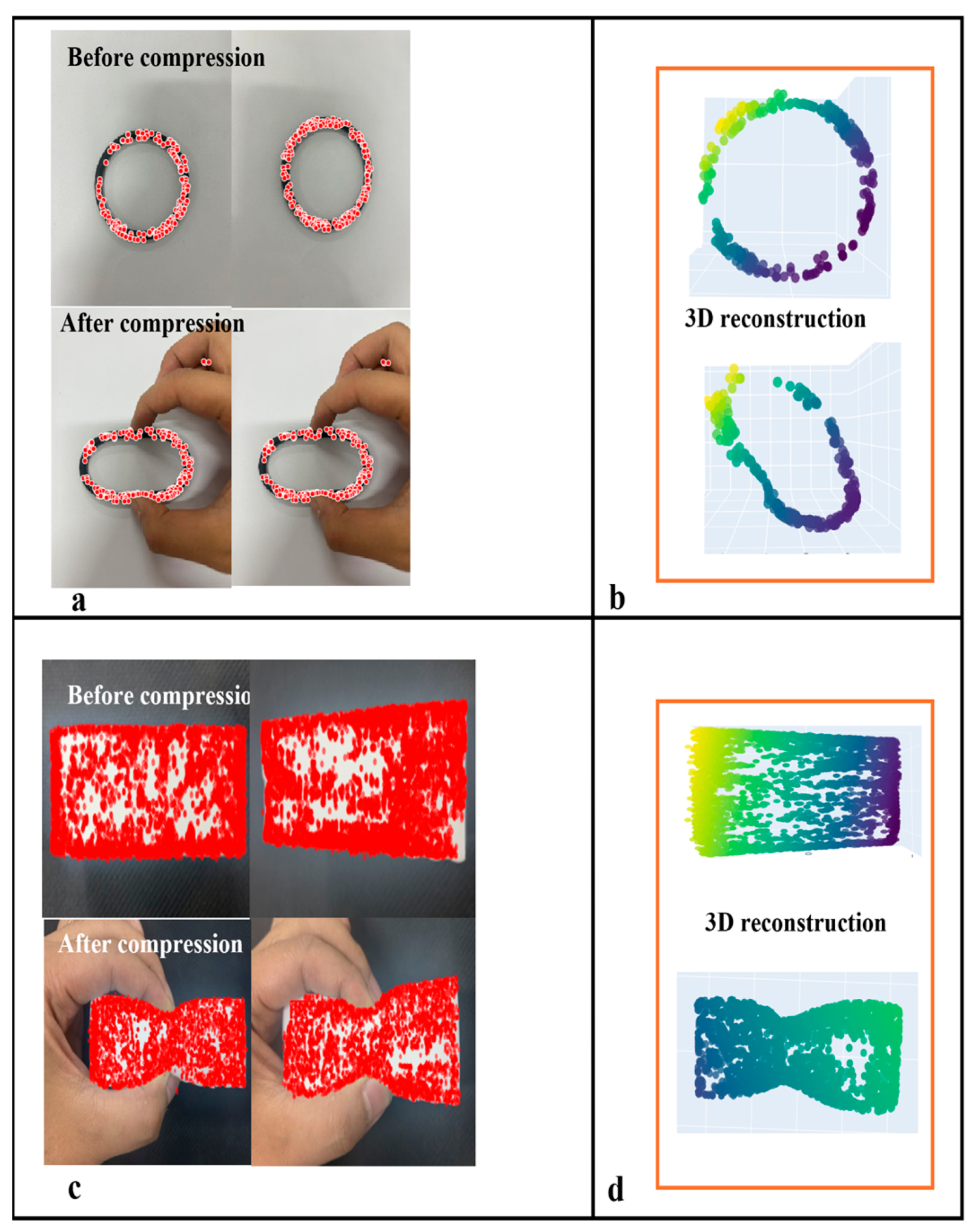
When reconstructing 3D displacement fields using feature-fusion algorithms, accurate acquisition of the feature information of the target object and grasping parameters is a prerequisite, making the precise definition of object features essential. In general applications, feature points refer to distinctive local structures in images that satisfy certain criteria, such as repeatability, distinctiveness, geometric invariance, and computational efficiency. In the proposed method, critical feature points for deformable object grasping are defined as local image structures that satisfy the following criteria: (1) salient features within the object-gripper contact region or (2) features exhibiting significant spatial or geometric state variations during object deformation. Multiple feature points from the contact region images can be tracked to monitor their displacements across different deformation states or consecutive frames. The displacement vectors of these feature points were then analyzed to quantify the local strain and global deformation patterns on the contact surface using the computed distance relationships within the point set. To validate method generality, we selected standardized black nitrile butadiene rubber (NBR) O-ring gaskets as representative test specimens, using the following specified parameters: outer diameter 65 ± 0.2 mm, cross-section diameter 5 ± 0.1 mm, and Shore A hardness 70 ± 2. These gaskets exhibit smooth surfaces and perfectly circular cross-sections. Although simple, these are representative geometric characteristics that thoroughly validate the capability of the algorithm to extract fundamental geometric features and establish benchmark references for subsequent analyses of complex-shaped objects. Although O-rings were used for validation, the feature fusion algorithm (SuperPoint-SIFT) and FEA framework are inherently generalizable. SuperPoint handles low-texture regions using deep semantic perception, while SIFT ensures geometric invariance, enabling the method to adapt to objects with diverse shapes and materials.
(a) Displacement points of O-ring gaskets.
These represent the terminal points of the displacement vectors between the actual positions under external loading and the theoretical positions in the unloaded state. The displacement magnitude can be determined by comparing the measured post-load positions with the initial unloaded positions, as illustrated in
Figure 1—that is, displacement point
of the O-ring gaskets characterized the local deformation under loading. We define the feature point displacement vector as the spatial vector difference between the measured deformed position
and the theoretical undeformed position
P (both 3D points in the world coordinate system):
.
(b) Forced bearing contact points.
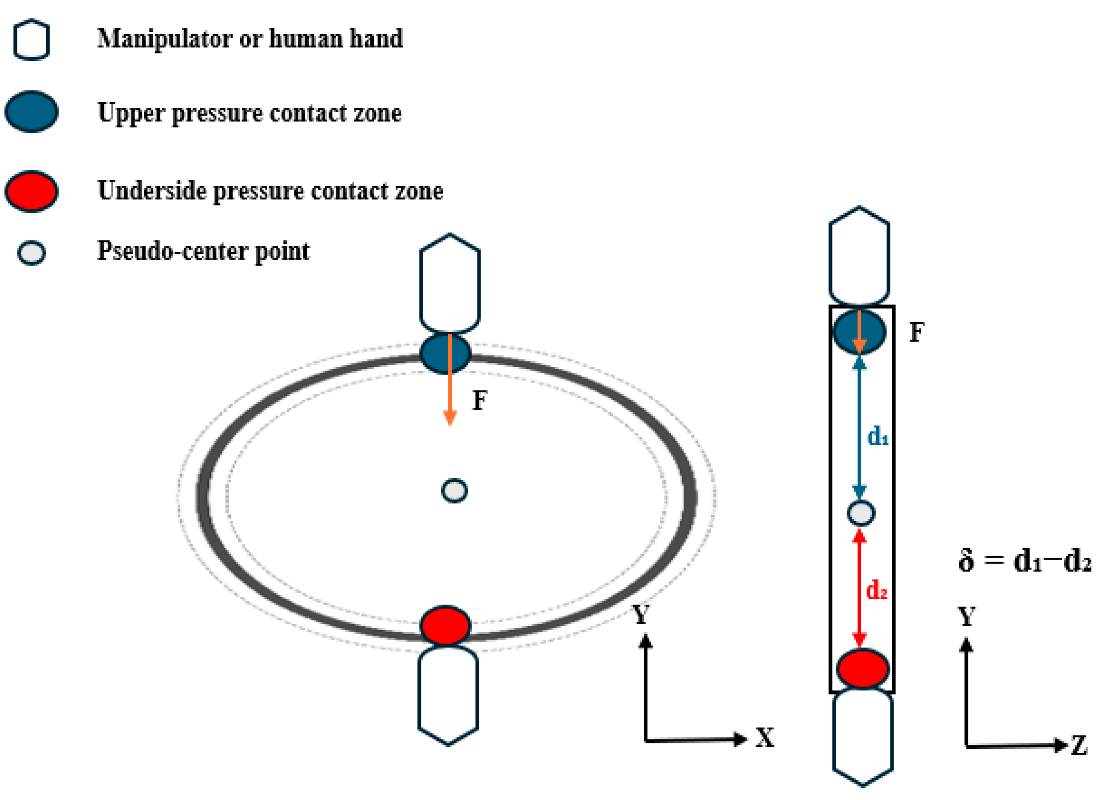
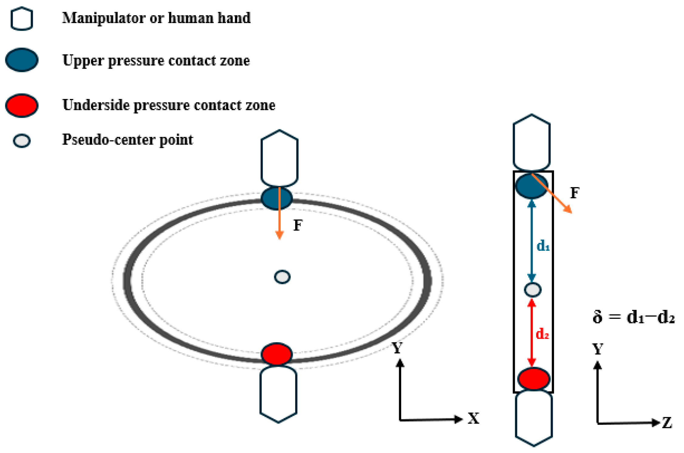
The contact feature points
and
represent the vertex regions formed during the gripper–O-ring interaction, defined as the uppermost and lowermost points of the contact area contour, respectively, as shown in
Figure 2 and
Figure 3. The pseudo-center-point
is defined as the representative geometric center of the O-ring in our study. The interboundary distance
indicates the contact zone span; the reduction in this zone under a constant contact area shows a positive correlation with the applied pressure.
Pressure distribution symmetry serves as a critical indicator for evaluating the vertical equilibrium. We quantify the symmetry by computing the offset
δ between upper/lower pressure centroids (
) and the pseudo-center as follows:
and denote the coordinate positions of the upper and lower contact pressure center points, respectively, while represents the system-defined pseudo-center reference point.
Under compression, the O-rings develop localized indentation deformations (forming contact feature points), and the spatial distributions of these deformations provide crucial grasp state indicators. Pressure distributions exhibit two modes: isotropic (symmetric centroids creating uniform stress fields) and anisotropic (asymmetric deformation from the centroid offset causing non-uniform stresses). The gasket’s mechanical state is quantified using both 3D feature-point distributions and δ: when δ ≈ 0, coincident centroids indicate equilibrium with axisymmetric indentation and uniform annular contact, and increasing δ values reflect growing asymmetry; these mechanical characteristics enable a discriminative grasp-state assessment.
When robotic/human hands grasp objects, HSV color-space segmentation is employed due to its perceptual uniformity and robustness to illumination variations. Unlike RGB, HSV separates luminance (
V) from chrominance (
H and
S), which minimizes the impact of lighting changes during the grasping process. This method provides reliable foreground masking for feature extraction in the environment.
The functionM(x,y) outputs 1 when a pixel’s hue H(x,y), saturation S(x,y), and brightness V(x,y) simultaneously fall within their respective threshold ranges, [, ], [, ], and [, ], and 0 otherwise.
2.1. Fusion Feature Extraction and 3D Reconstruction
Figure 4 illustrates the feature fusion extraction and displacement field reconstruction pipeline, where the output displacement vector is considered as the boundary condition for mechanical estimation. The integrated feature extraction and 3D reconstruction approach comprises four key steps [
18]: (1) SuperPoint-SIFT feature detection, (2) feature point matching, (3) essential/fundamental matrix estimation via epipolar geometry, and (4) triangulation-based 3D point-cloud reconstruction. Our approach synergizes traditional SIFT features with deep learning-based SuperPoint features to enhance feature extraction for subsequent 3D reconstruction.
To address the feature-matching challenges in markerless low-texture object deformation detection, we independently extracted SuperPoint features (for low-texture regions) and SIFT features (for texture-rich regions) within segmented ROIs and subsequently merged them using a late-fusion strategy. The pipeline involves (1) independent feature points and descriptor extraction using SuperPoint [
18] and SIFT, (2) spatial filtering via shared foreground masks, (3) k-nearest neighbor matching with Lowe’s ratio test for both feature types, and (4) merged match-pair refinement using RANSAC [
19].
Figure 5 illustrates the two-view stereo vision pipeline used for 3D reconstruction [
20]: using matched feature pairs and camera calibration parameters, we implemented structure-from-motion (SfM) [
21] via OpenCV’s findEssentialMat and recoverPose functions, followed by dense point cloud reconstruction using triangulatePoints [
22]. This process adheres to standard epipolar constraints and triangulation principles [
23], thereby minimizing reprojection errors for pose estimation and 3D point optimization.
2.2. Contact Force Estimation Based on Displacement and Finite Element Analysis
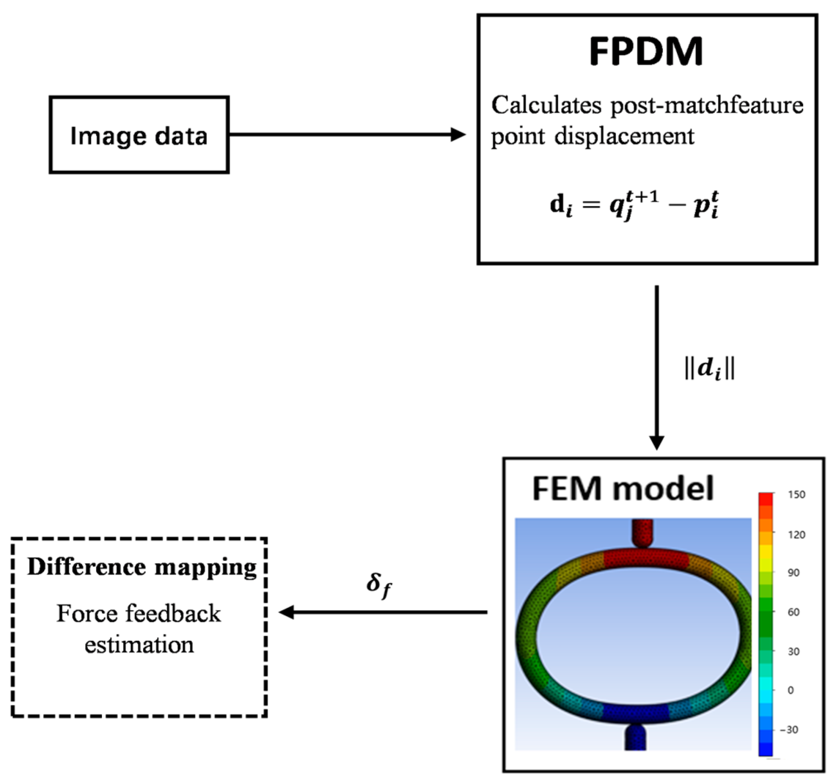
The proposed method acquires the displacement variations in the surface feature points through 3D reconstruction, which are then input as boundary conditions into a finite element model. Integration with feature-fusion algorithms enables contact-force computations, as shown in
Figure 6.
The Feature Point Displacement Module (FPDM) computes the displacements of the matched feature points, taking pre- and post-deformation 3D point clouds as inputs, and outputs the mean displacement vector of the matched point pairs as the FEA boundary conditions. Here, denotes the feature point displacement vector and represents the stress computed by the FEM based on these displacement vectors.
Following feature fusion and 3D reconstruction, the deformation displacement was quantified by establishing precise correspondence between the pre- and post-deformation point clouds. For matched point pairs (
, where
denotes the i-th point in the pre-deformation cloud
and
denotes the j-th matched point in the post-deformation cloud
, the displacement vector
is computed as follows:
This vector explicitly captures both the direction and magnitude of the 3D displacement. To quantify the displacement amplitude, we computed the Euclidean norm (geometric length) as follows:
Superscripts
x,
y, and
z denote the three coordinate components. This computation captured both local displacements and global deformation patterns. The obtained surface displacement vectors
serve as boundary conditions for the finite element model. We employed a hyperelastic constitutive model with the Mooney–Rivlin strain energy function to characterize the rubber material properties as follows:
The Mooney–Rivlin model was selected for its capability to accurately characterize the deformation behavior of rubber-like materials, where
is the strain energy density,
and
are material constants;
and
denote the first and second deviatoric strain invariants, representing the isochoric deformation resistance and shape-change resistance, respectively, and
J indicates the volume ratio (
J < 1 corresponds to compression). These parameters were calibrated using uniaxial compression tests on NBR O-rings to ensure physical accuracy. Finite element discretization yields a nonlinear equation,
, where K is the stiffness matrix and F is the nodal force vector. The Newton–Raphson iteration [
8] solves these equations to obtain the displacement-stress responses. A precomputed FEM forward simulation database establishes a mapping between the feature point displacements and contact forces, enabling direct force estimation via displacement-based interpolation.
The proposed framework establishes a nonlinear displacement-stress field mapping, creating a complete vision–mechanics coupling system that enables FEM-based force detection solely through feature point deformation observations.
2.3. Based on the Keyframe Feature Point-Finite Element Collaborative Comparison Method
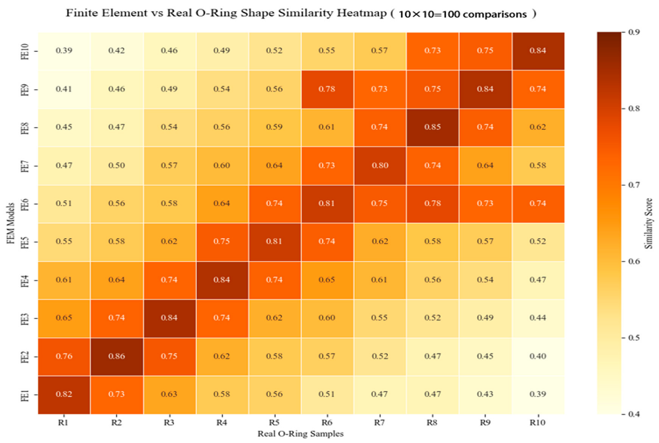
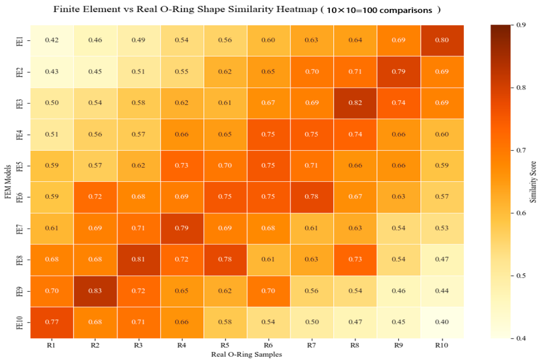
The video temporal alignment begins with uniform frame sampling , where the i-th keyframe position , which eliminates segmentation-dependent noise by extracting ten keyframes without relying on shot-boundary detection. This enables localized feature similarity computation between video sequences. The extracted frames underwent a three-stage similarity validation: (1) feature matching using the Euclidean distance, (2) point cloud registration via Iterative Closest Point (ICP), and (3) similarity assessment. This pipeline robustly bridges the 2D image features for 3D geometric verification.
During feature matching, given two feature sets
and
, we established a cross-view correspondence by performing a k-nearest neighbor search (
k = 2) [
24] for each query feature in the target descriptor space.
Here,
d1 and
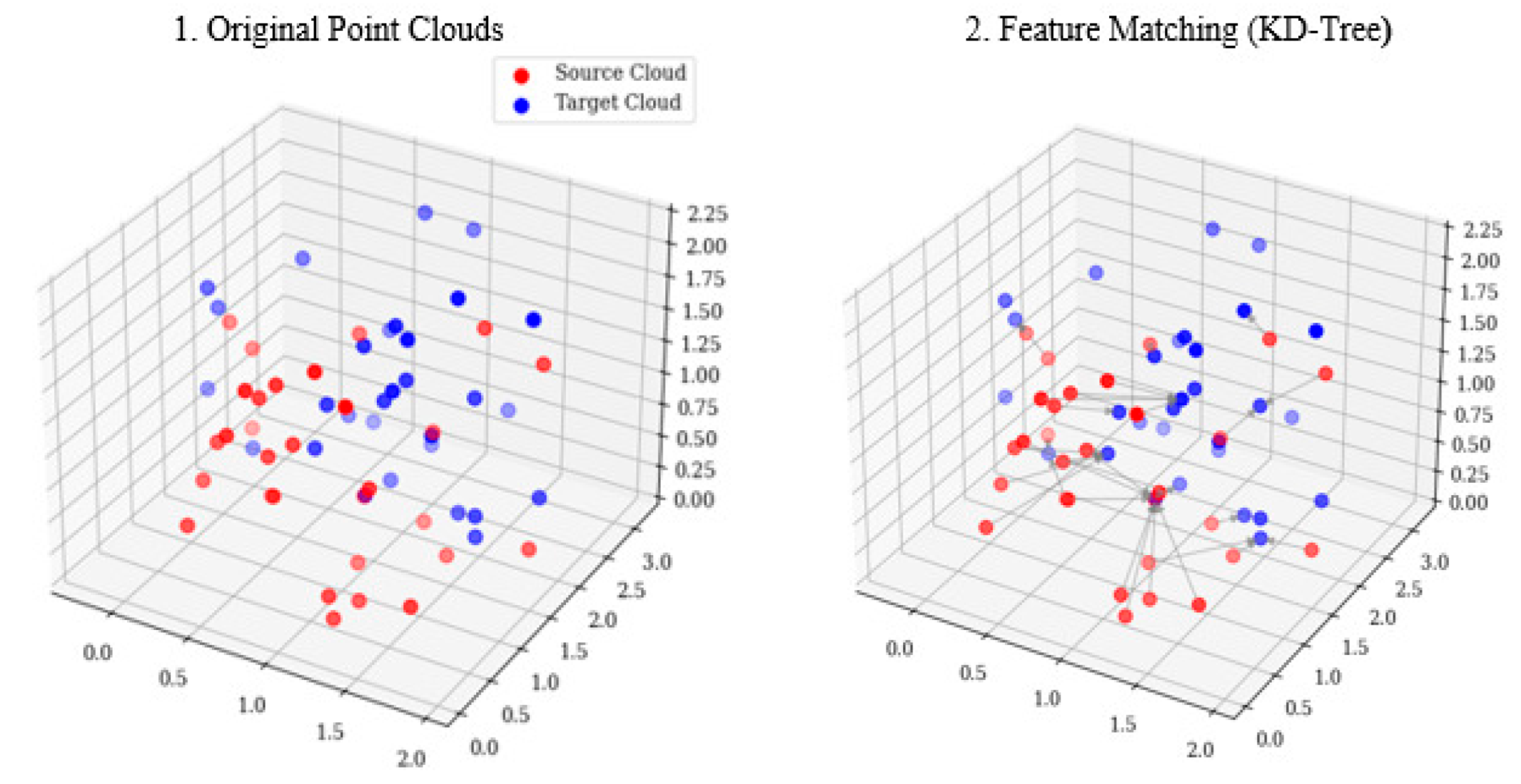
d2 denote the distances to the first- and second-nearest neighbors, respectively. The matches output contains correspondence lists with DMatch objects indicating best/second matches in the target images, where smaller distances imply higher feature similarity. Point cloud registration aligns 3D features from multiple views into a unified coordinate system via (1) a KD-tree-based nearest-neighbor search to establish the initial correspondence between point clouds
P1 and
P2, where each
p ∈
P1 finds its closest point in
P2, as shown in
Figure 7, and (2) computing optimal rigid transformation (rotation
R and translation
t) via SVD by minimizing the squared Euclidean distance,
, where
p1i ∈
P1 and
p2i ∈
P2 are matched pairs. The derived transform optimally aligns the point clouds [
25].
The similarity assessment employs the mean Euclidean distance between registered point clouds as follows:
where
T denotes the estimated rigid transformation,
, and
are the matched point pairs, and
N is the number of valid correspondences. To mitigate scale variation, we defined the normalized similarity score as follows:
Here, represents maximum inter-cloud distance, normalizing similarity to [0, 1] (1: perfect alignment; 0: no match).
High similarity scores indicate geometric deformation consistency between the real frames and FEA simulations, thereby providing foundational evidence for establishing cross-modal mapping. When the geometric similarity exceeds the thresholds, real-world deformations spatially correspond to the FEA predictions, enabling accurate stress/displacement field transfer from simulations to physical states.
The proposed method concurrently acquires experimental videos of the compressed objects and their corresponding FEA simulations, achieving spatiotemporal alignment through uniform temporal sampling and spatial point cloud registration. Video similarity matching establishes real-to-simulation mappings, ultimately enabling vision-based state estimation without a physical sensor, as shown in
Figure 8.
4. Conclusions
Conventional pressure sensors face limitations around hardware deployment and flexible scenario adaptation, whereas current vision-based force-estimation methods still exhibit insufficient robustness under markerless, low-texture, and microdeformation conditions. This study proposes a sensorless force-detection framework that integrates SuperPoint-SIFT feature fusion with FEA, enabling external force estimation by using 3D reconstruction and video feature comparison.
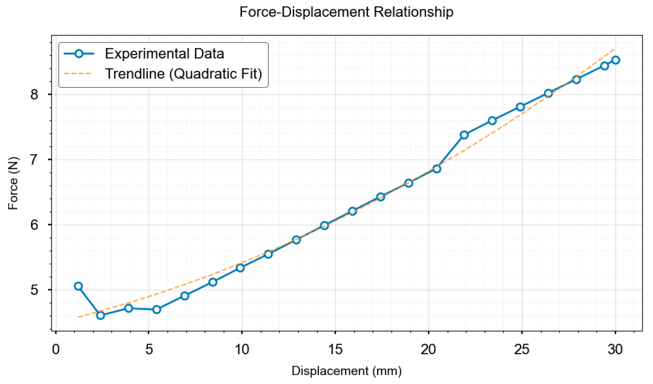
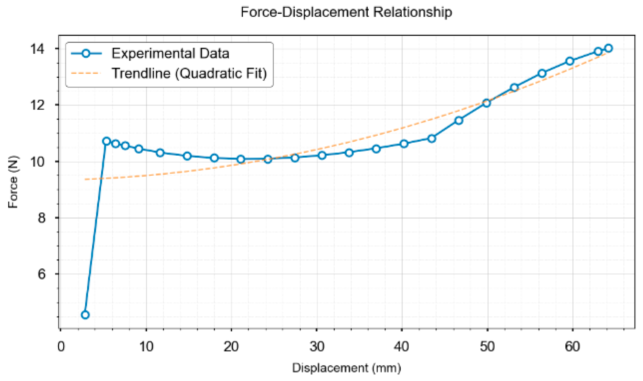
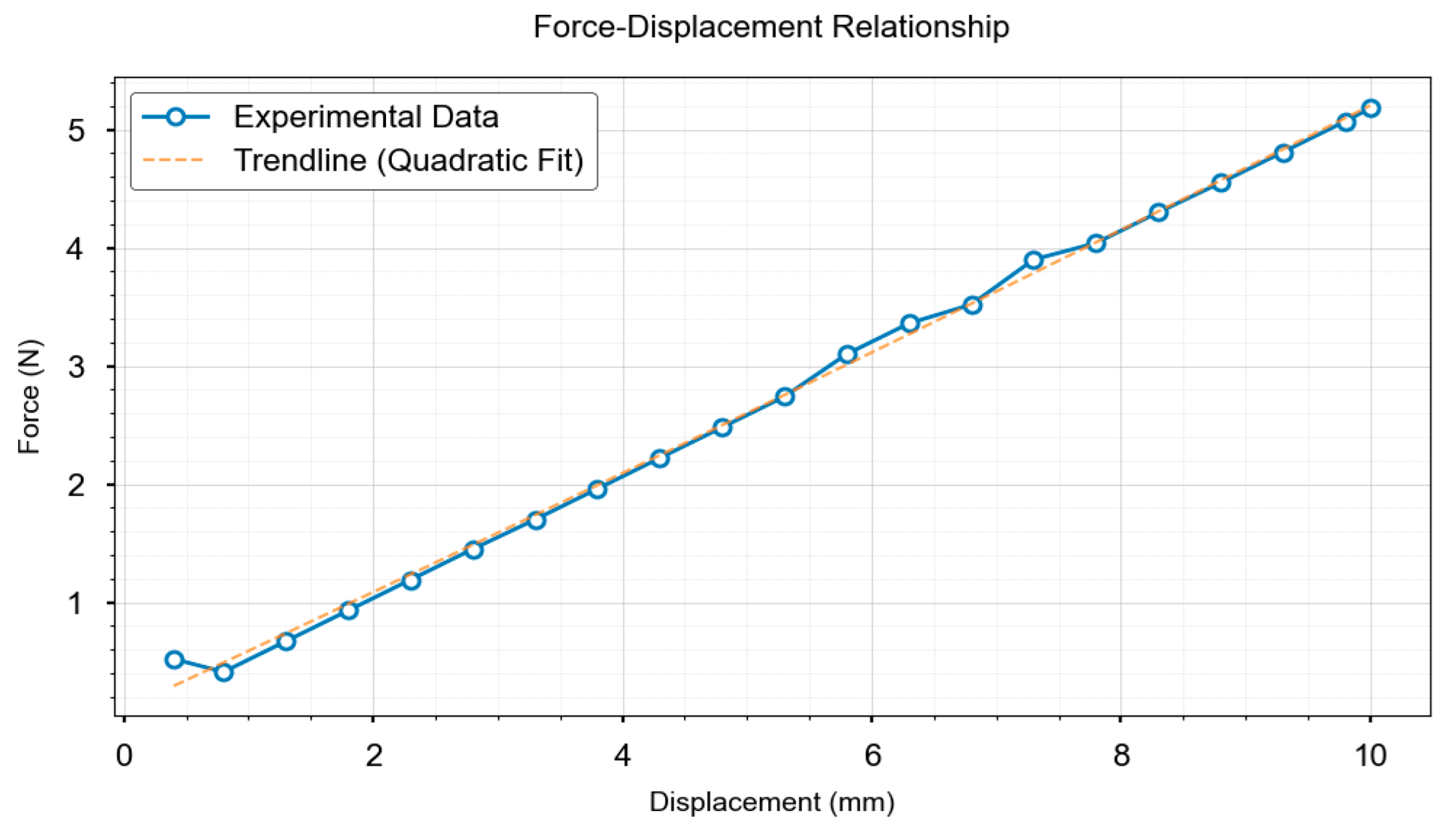
By combining SuperPoint’s semantic awareness and SIFT’s geometric invariance, we enhanced feature-matching robustness in markerless and low-texture scenarios. The novel vision-displacement FEA-fusion framework achieved sensorless contact force estimation with a mean error of <10 %. A video-based deformation dynamics analysis and similarity comparison validated the spatiotemporal consistency between the FEA predictions and actual deformations, establishing a reliable sensorless verification framework. The method is effective under markerless monocular conditions, estimating external stress distributions solely using visual data with notable generalizability. Although offline FEA reduces computational burden, the recalibration of material parameter changes (e.g., nonlinear hyperelasticity) substantially limits online adaptability. Current limitations include (1) robustness under extreme illumination/occlusion, (2) generalizability to complex geometries or heterogeneous materials, and (3) real-time performance for highly dynamic interactions. Future work will focus on (1) developing online material identification and ML-based FEA surrogate models to reduce parameter dependency and (2) optimizing algorithms with parallel computing for real-time performance. (3) In human–robot interaction applications, this method serves as a cost-effective alternative to conventional torque sensors, being particularly suitable for cost-sensitive and non-extreme high-speed collaborative scenarios such as delicate object manipulation and low-speed assembly tasks. However, under the current framework, its response latency and computational delays in highly dynamic operations (e.g., rapid grasping or sudden collision response) require further improvements through algorithmic acceleration and hardware co-optimization to fully meet the demands of high-accuracy real-time human–robot interactions. Despite these limitations, our method innovatively provides sensorless force perception, showing significant value in precision assembly and surgical robotics, which require high-accuracy force control. Further optimization can overcome the limitations of traditional force-sensing and advanced robotic dexterous manipulation technologies.

