
A Bipedal Robotic Platform Leveraging Reconfigurable Locomotion Policies for Terrestrial, Aquatic, and Aerial Mobility


Abstract
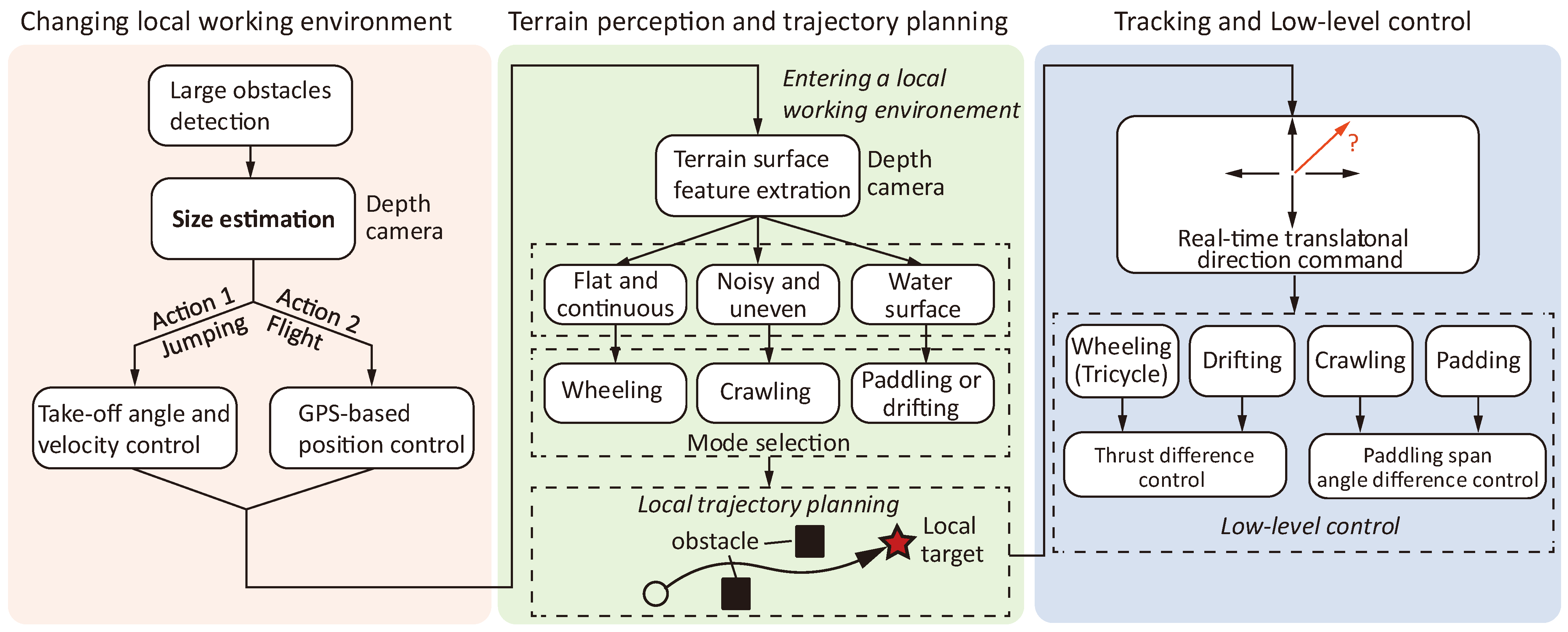
1. Introduction
2. Materials and Methods
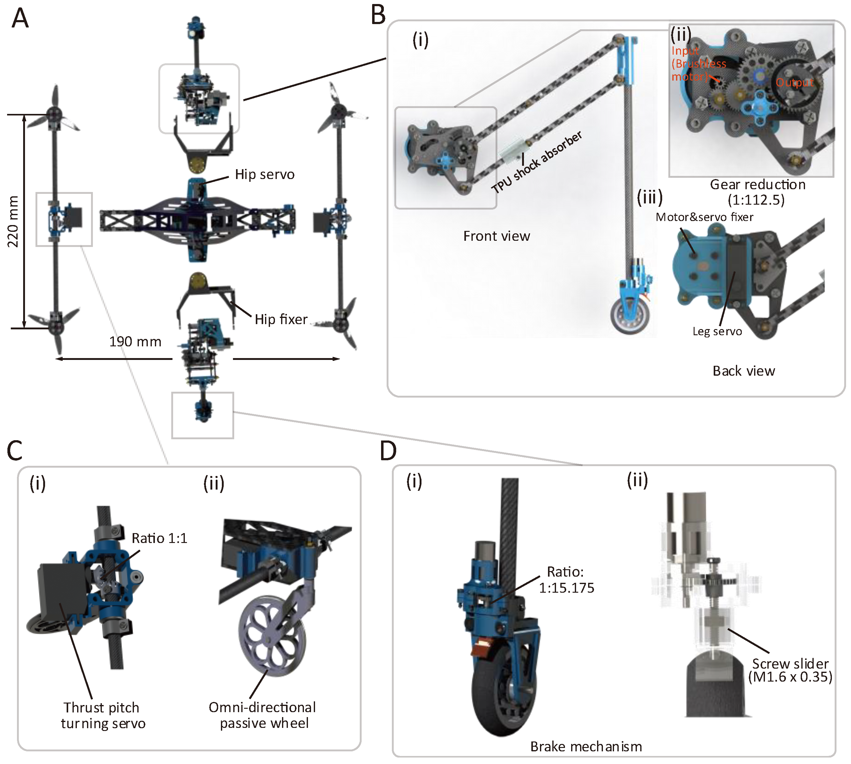
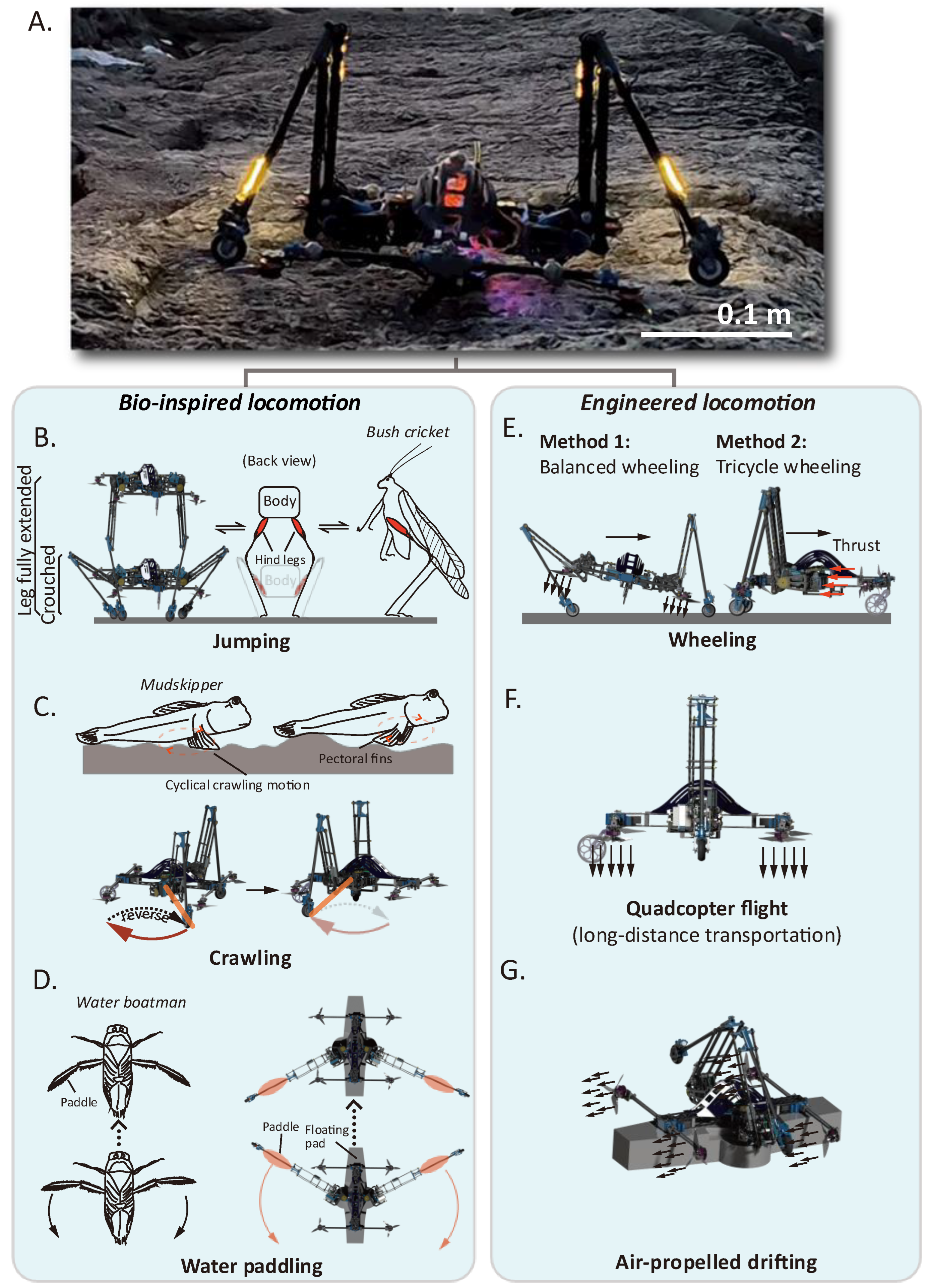
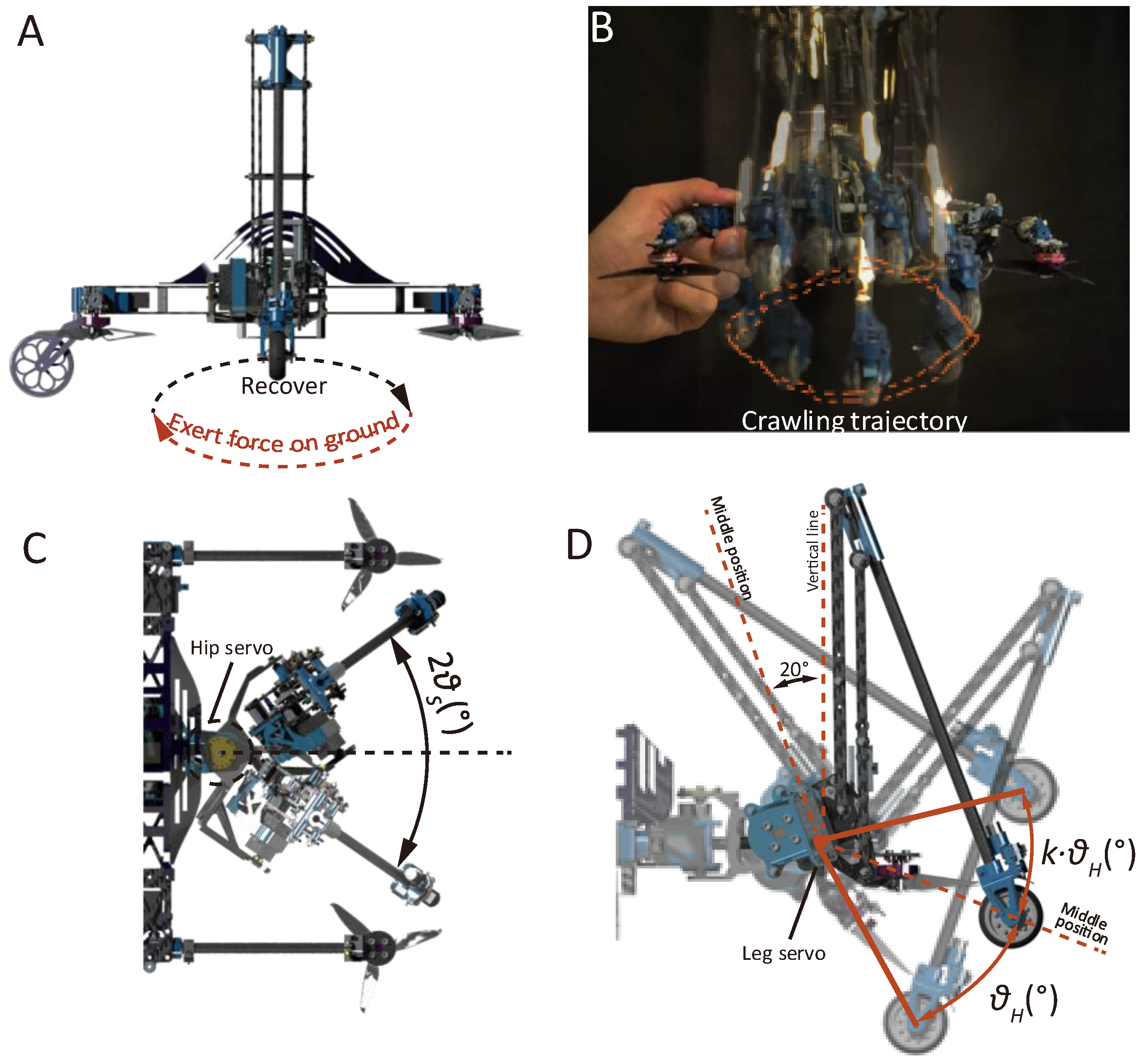
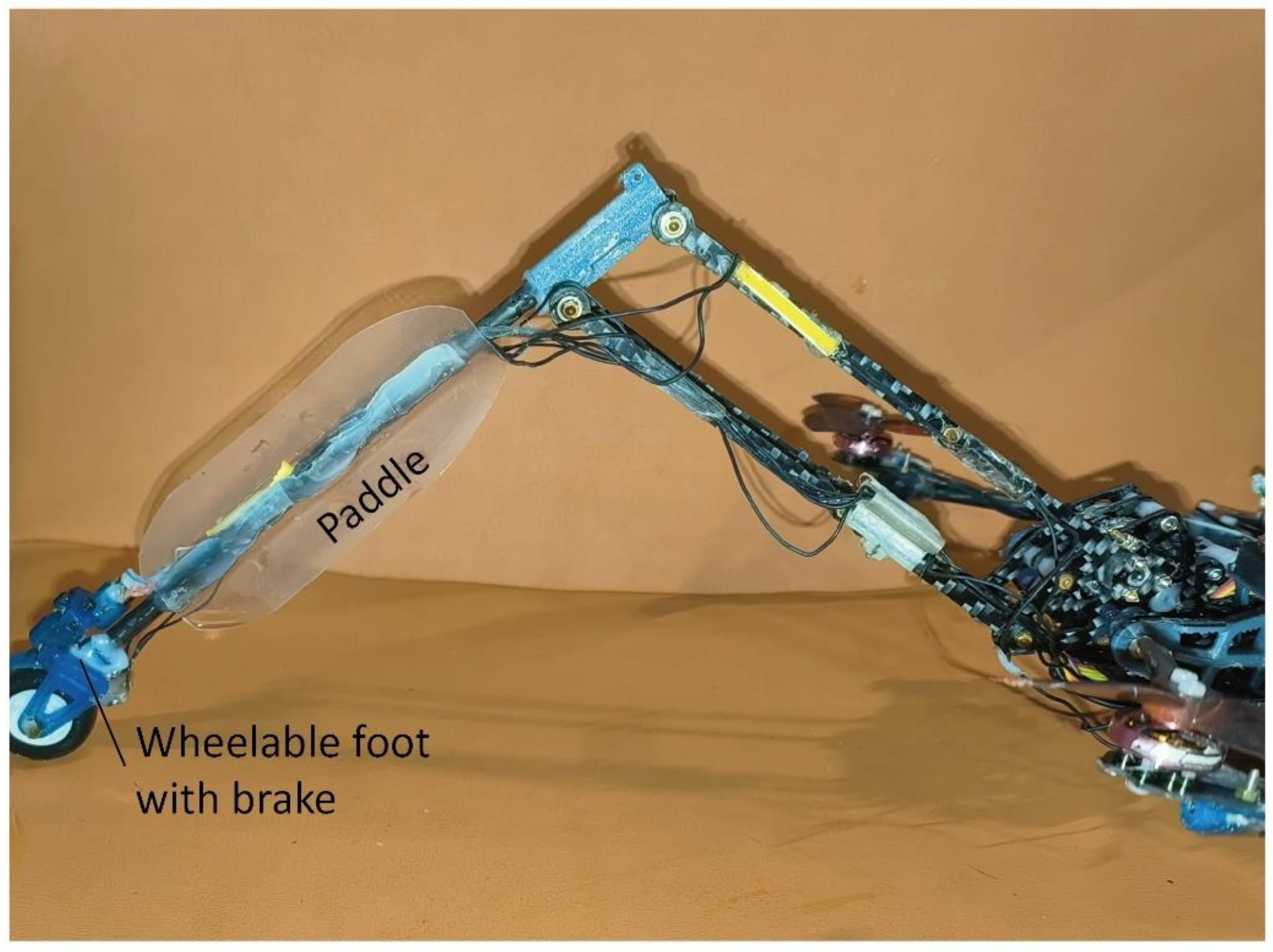
2.1. Demonstration of the Robot Structure and Locomotion Modes
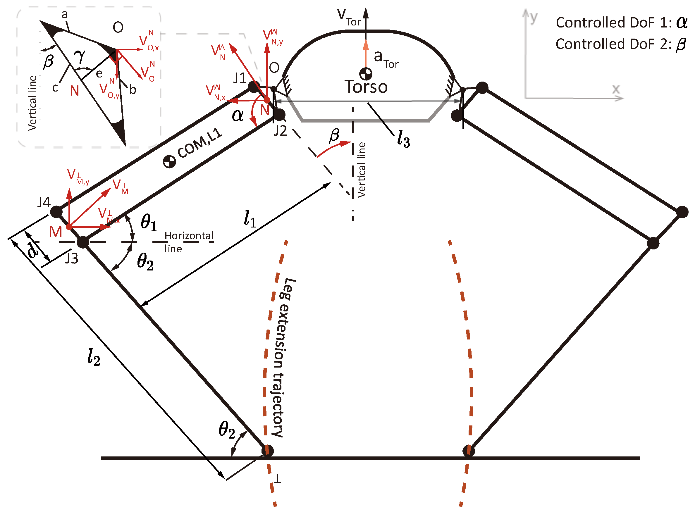
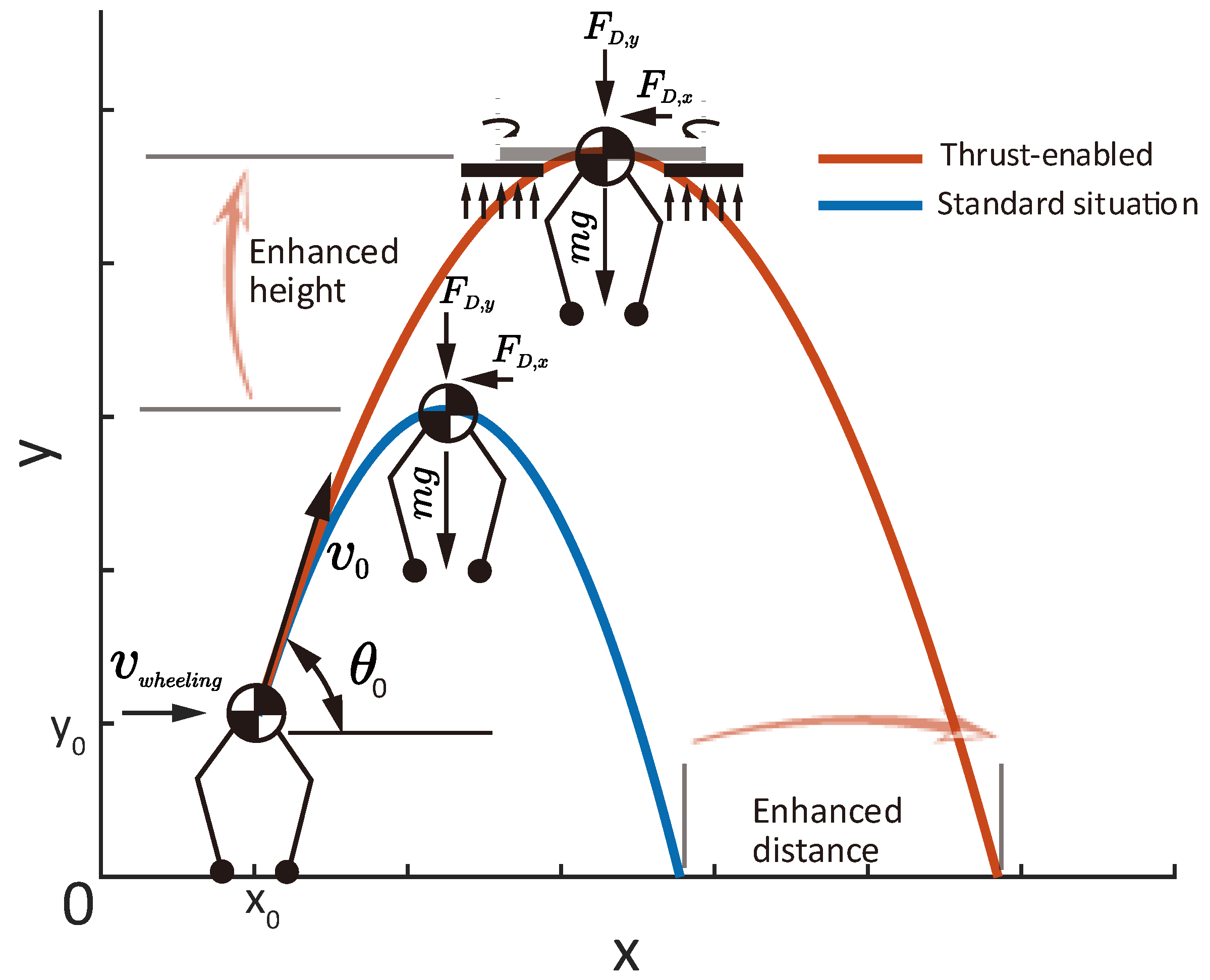
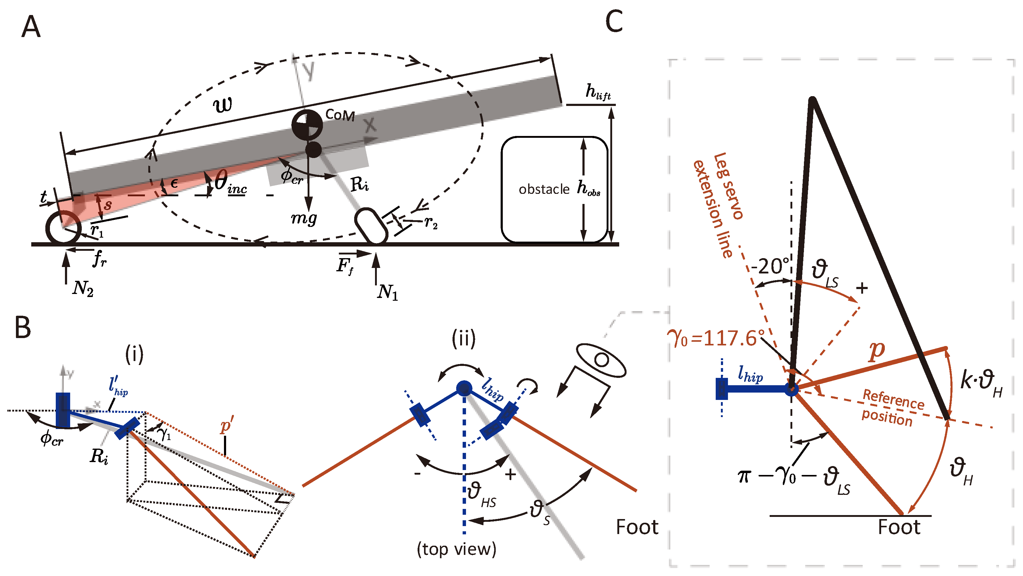
2.2. Analysis of the Jumping Acceleration and Aerial Phases
2.2.1. Kinematics Analysis of the Jumping Process
2.2.2. Aerial Phase Analysis
2.2.3. Motor Commands
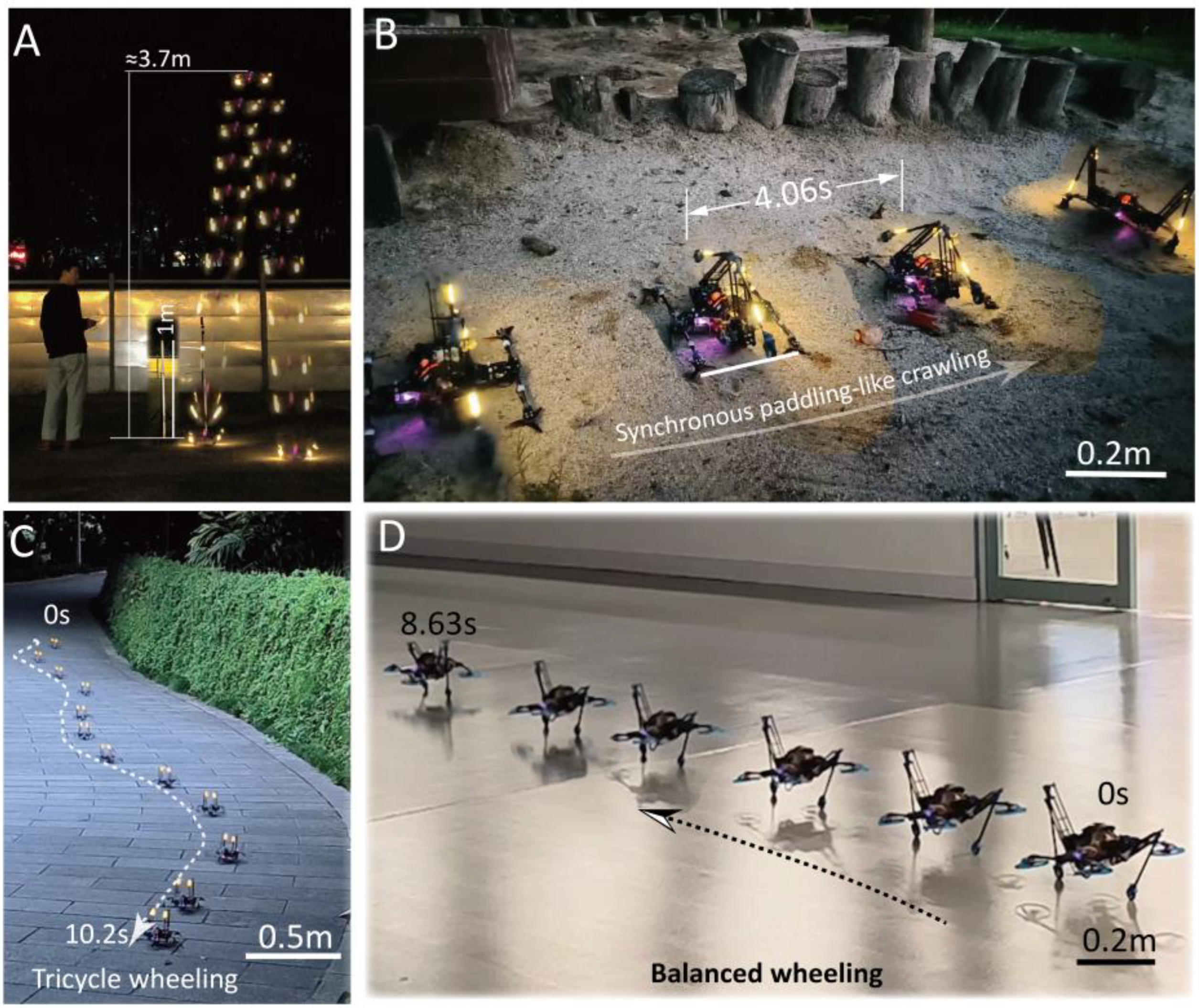
2.3. Synchronous Paddling-like Motion
2.3.1. Crawling Method
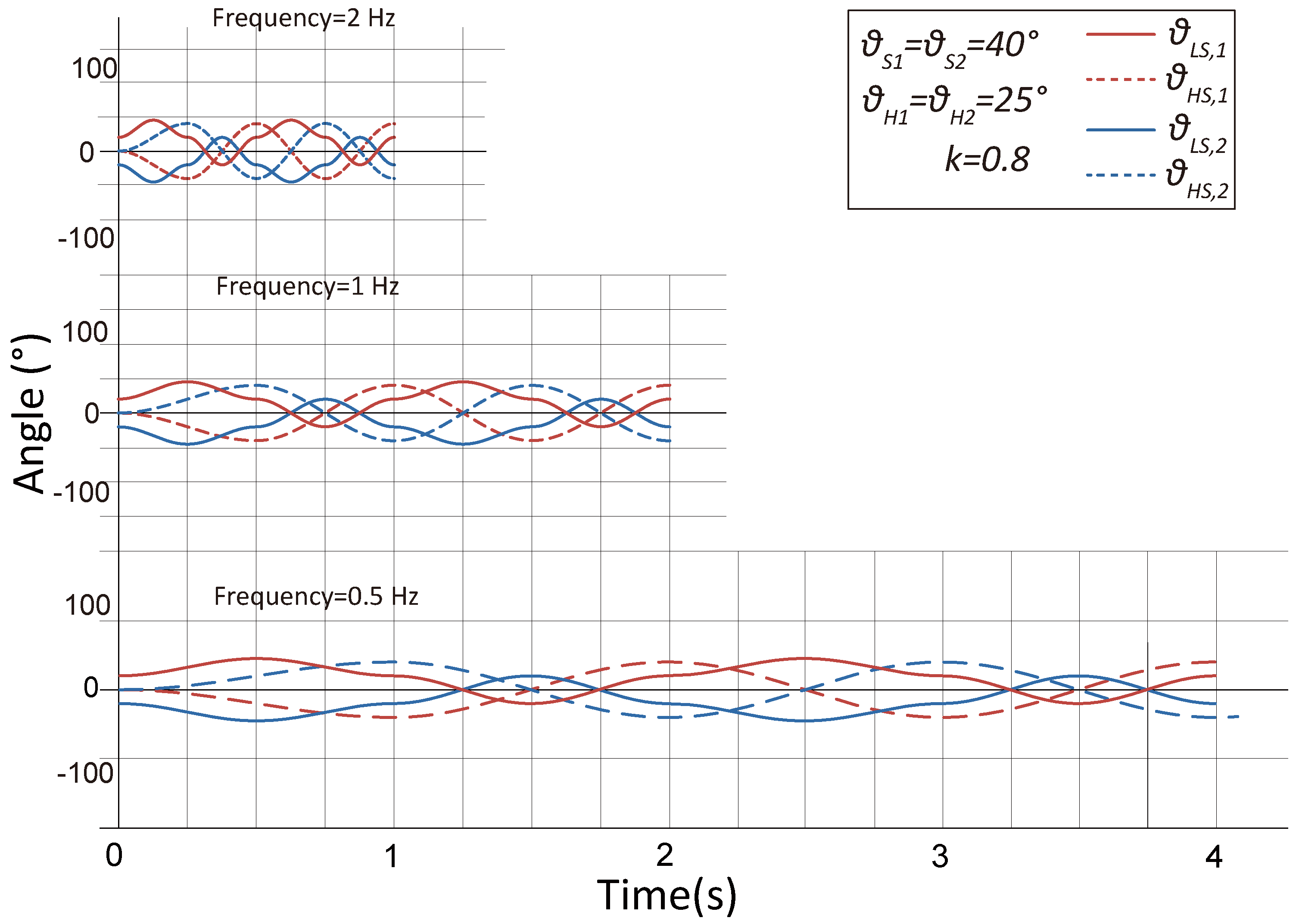
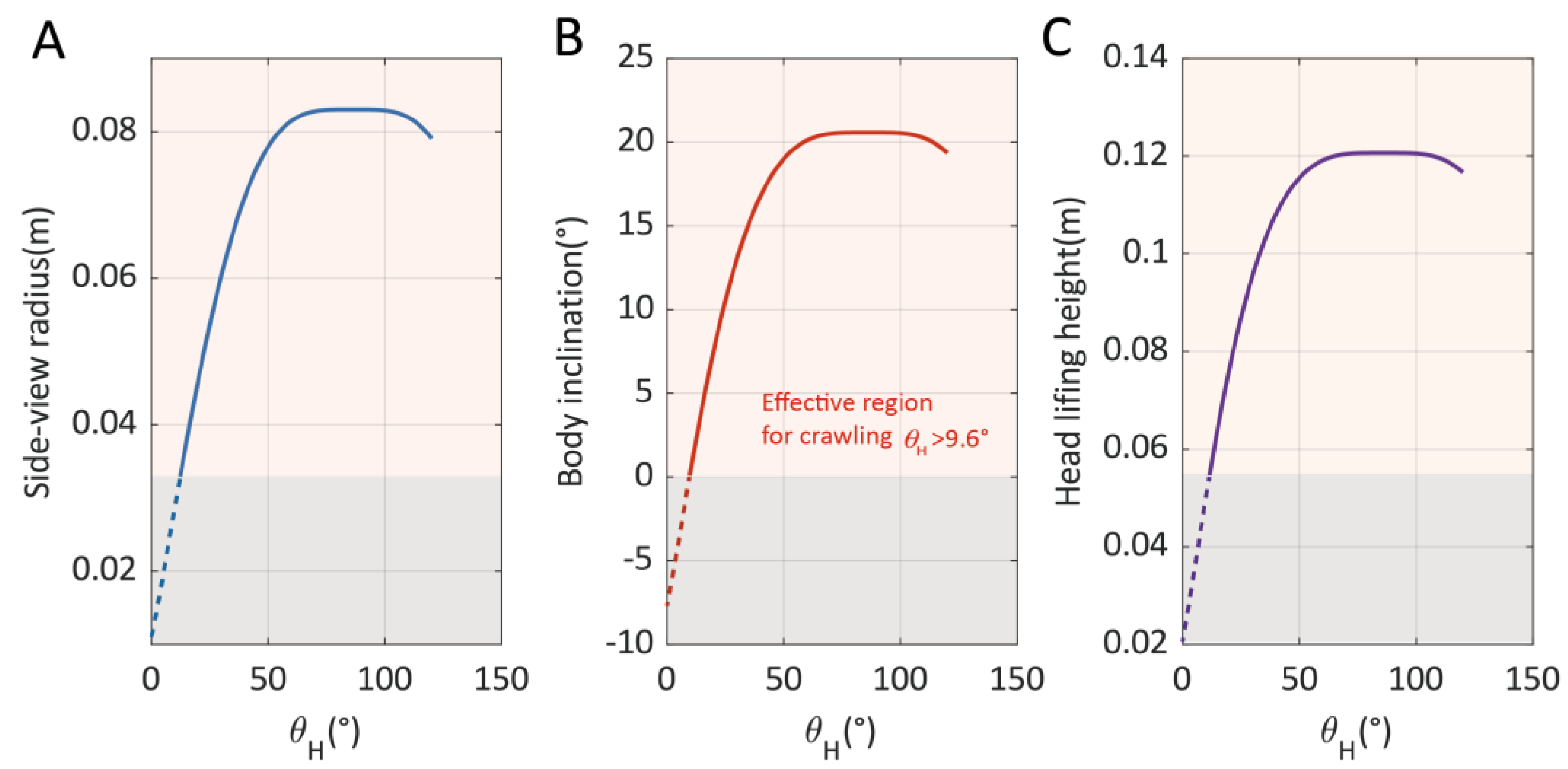
2.3.2. Crawling Motion Modeling
2.3.3. Water Paddling Design for the Swimming Mode
2.4. Method for the Wheeling Mode
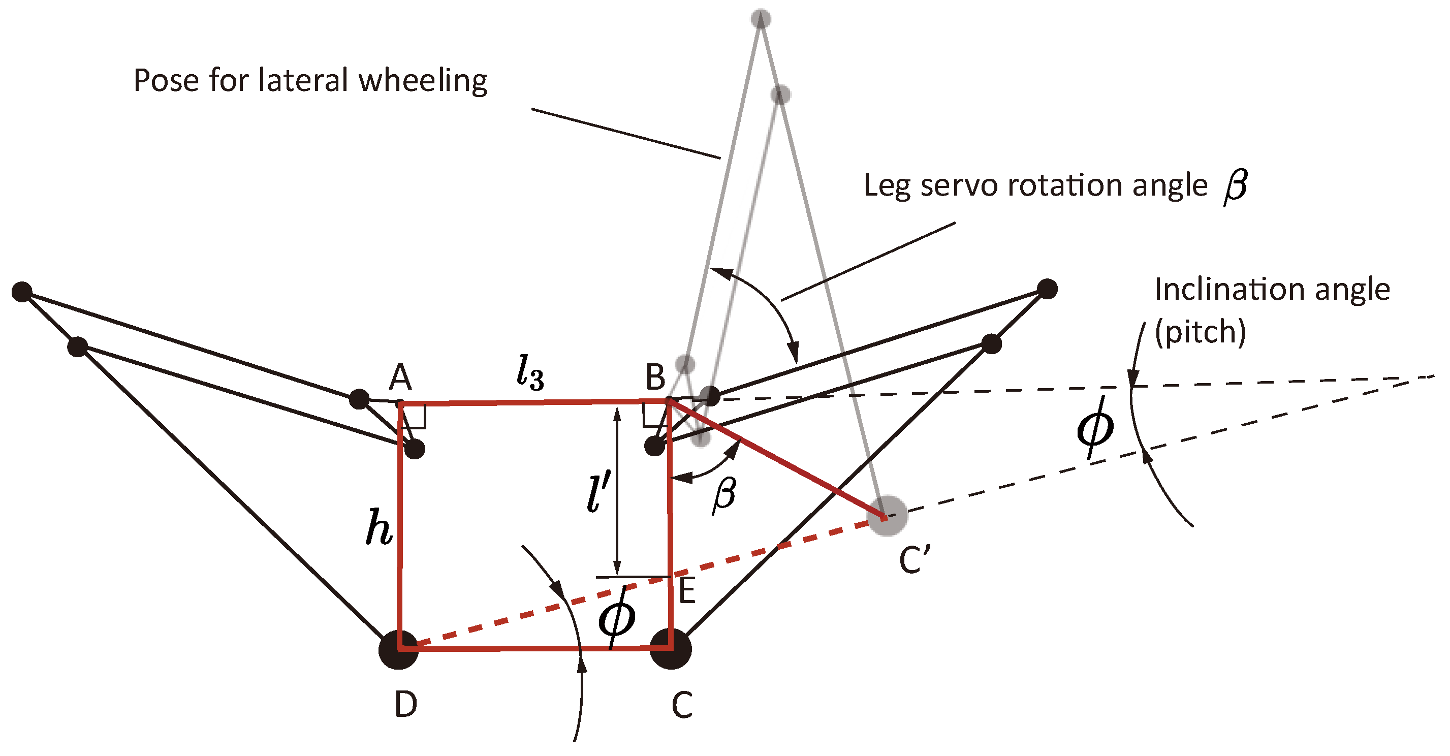
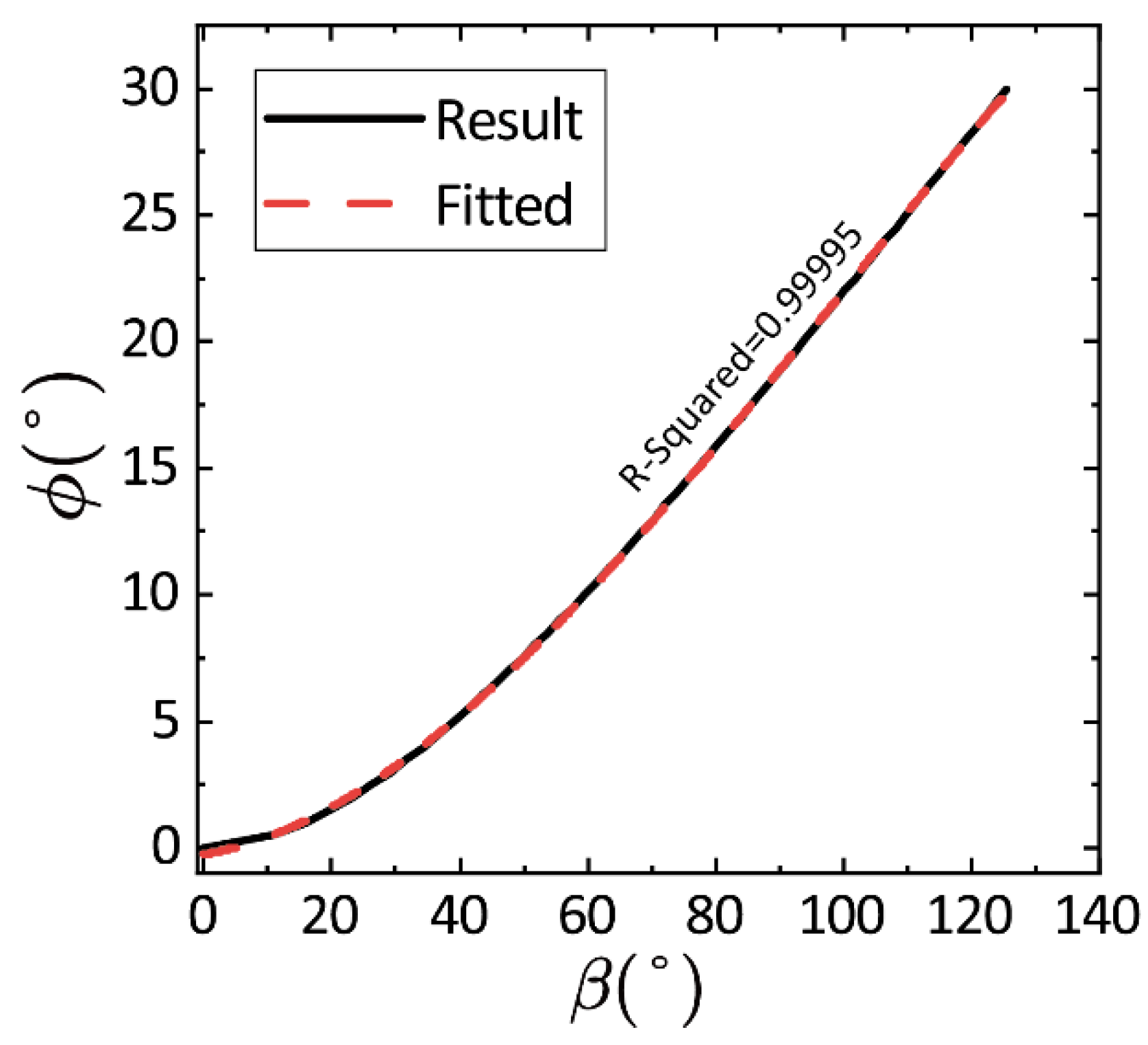
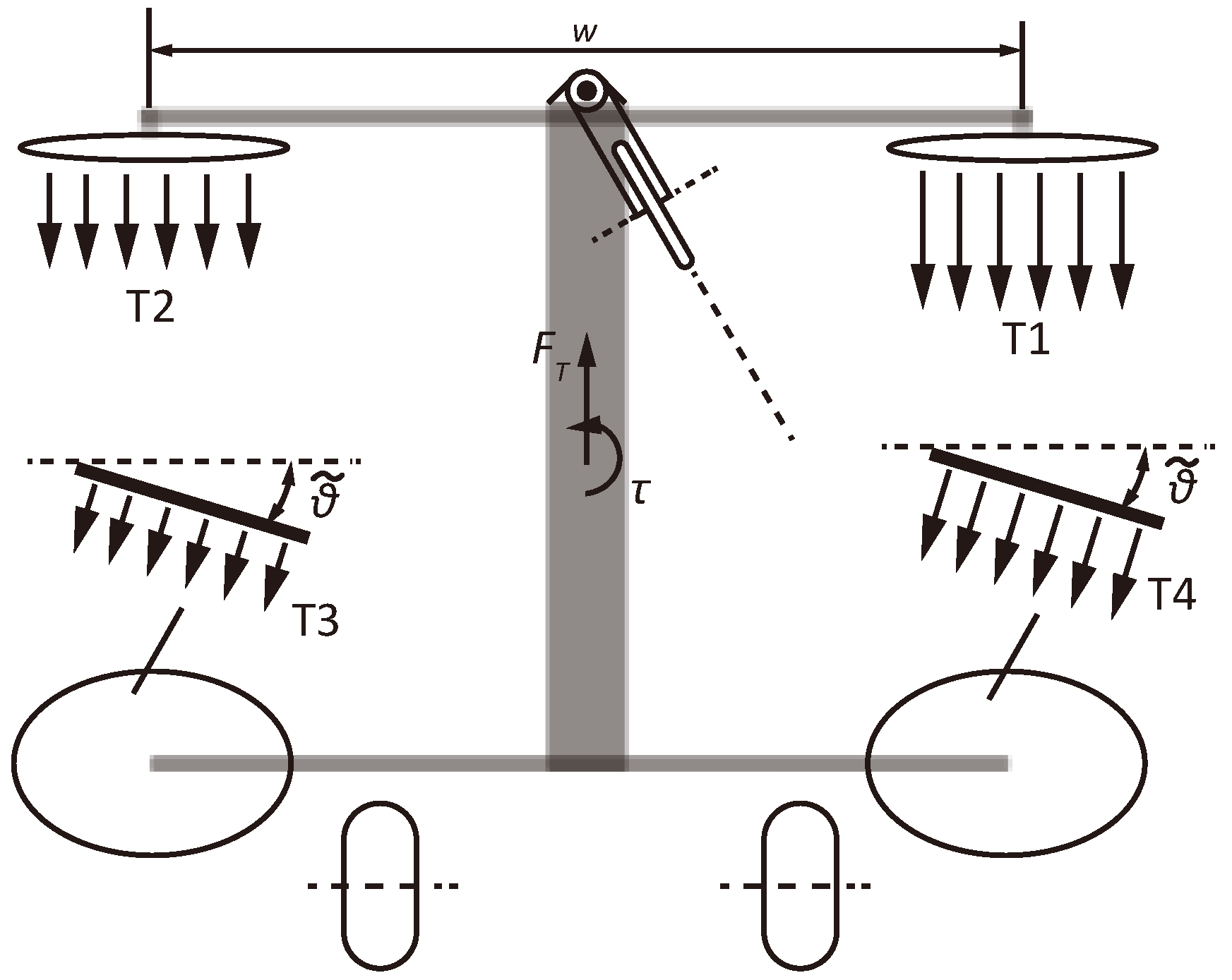
2.4.1. Balanced Wheeling Mode
2.4.2. Tricycle Wheeling Mode
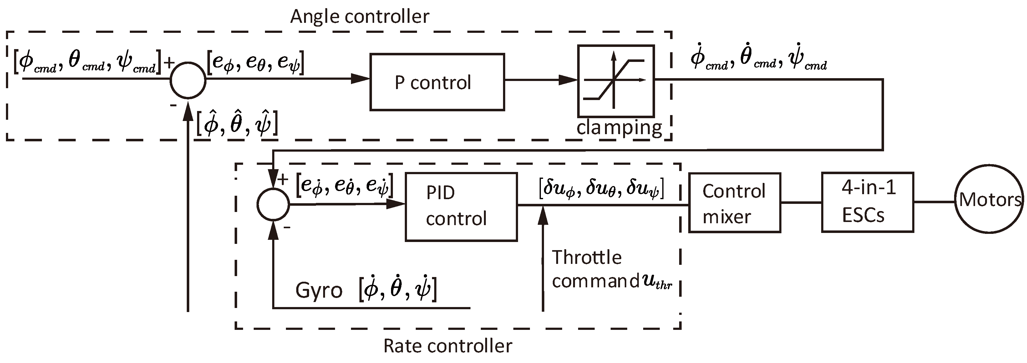
2.5. PID Attitude Controller for Balancing and Flight
3. Results
3.1. Validation of Terrestrial Locomotion Modes
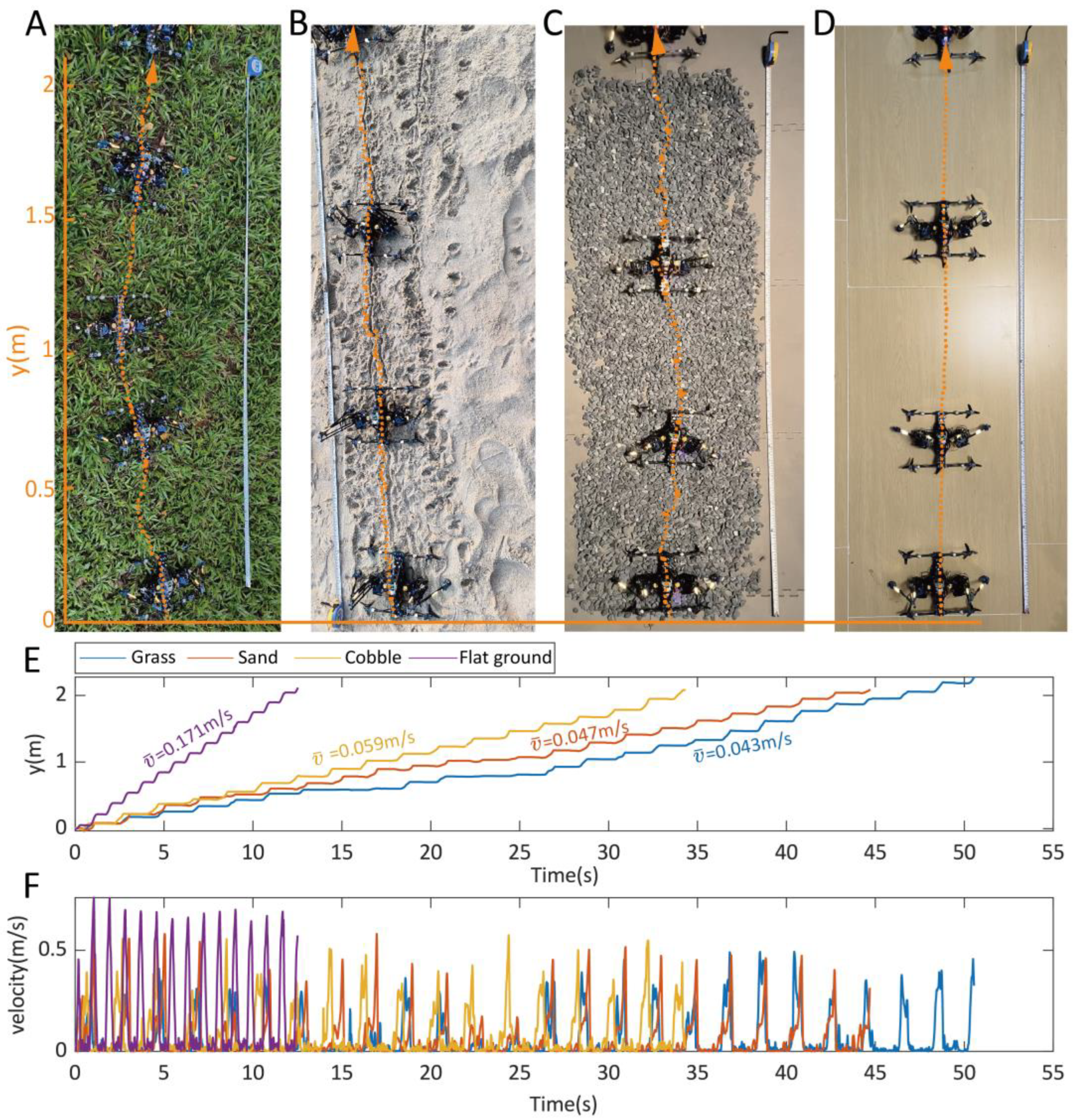
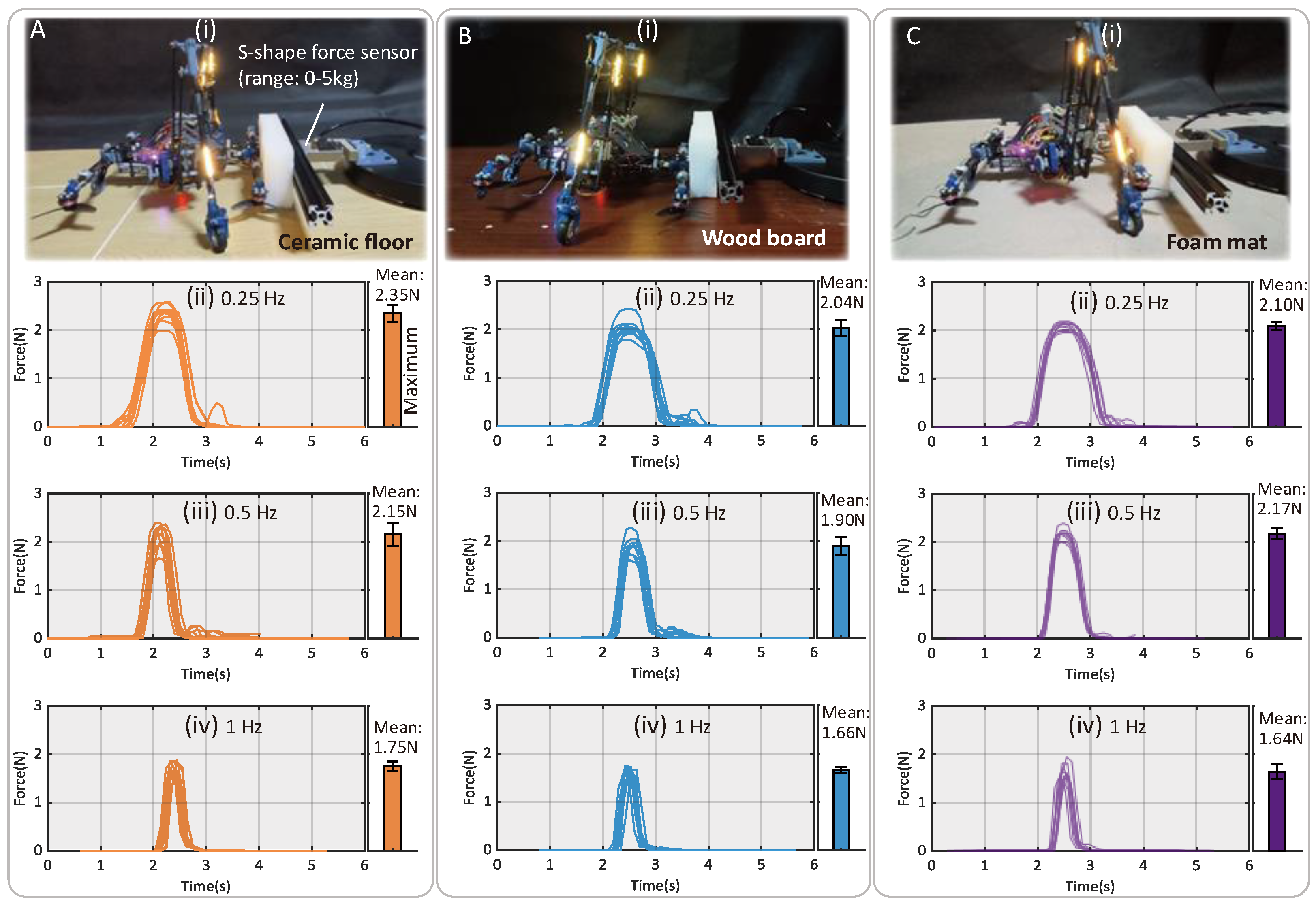
3.2. Synchronous Crawling on Various Terrains
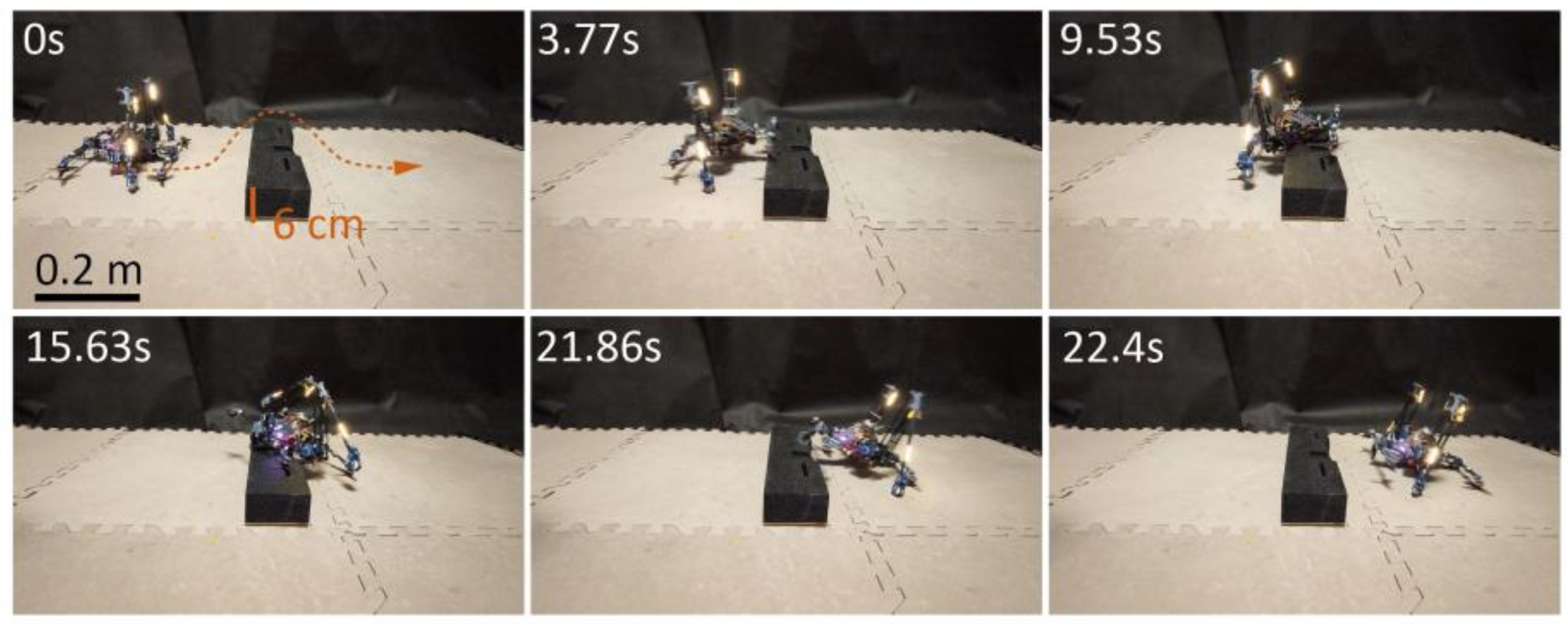
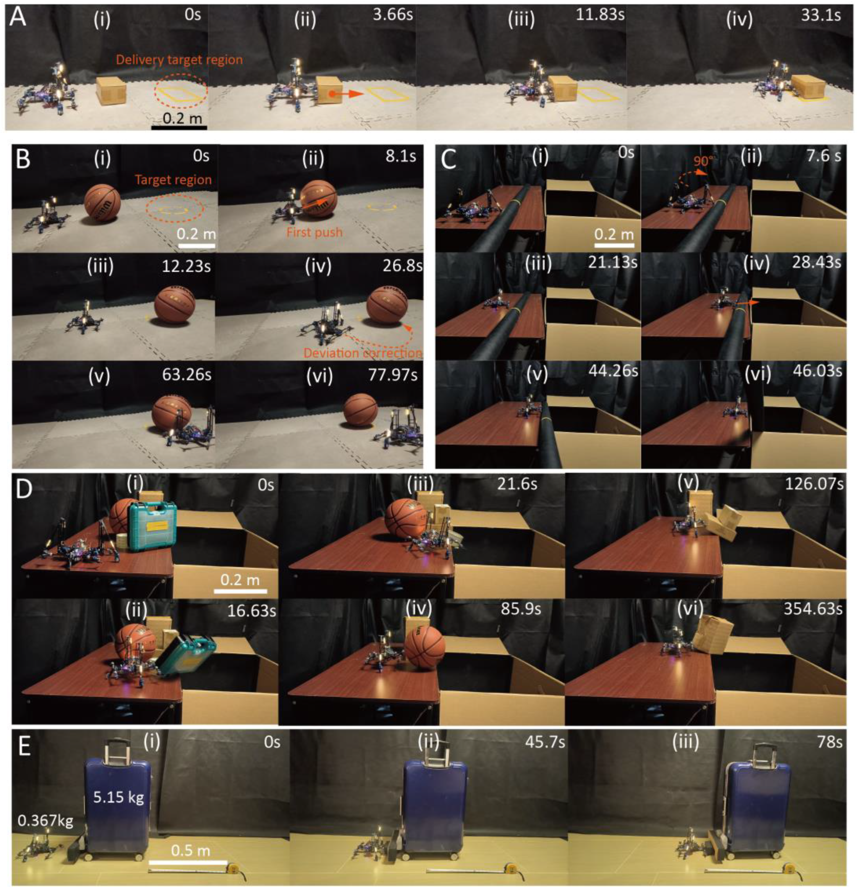
3.3. Object Transfer Tasks
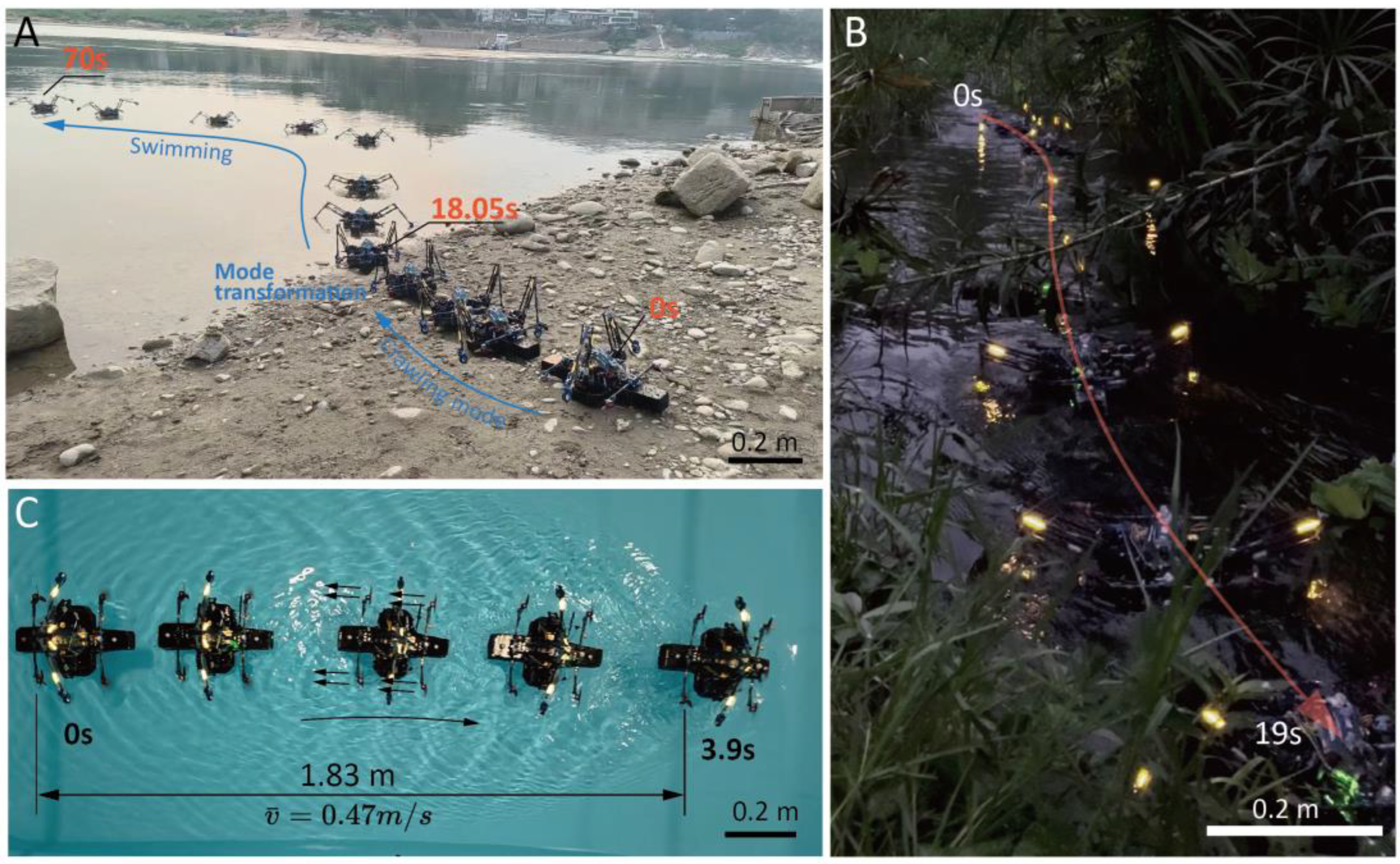
3.4. Locomotion in Aquatic Regions
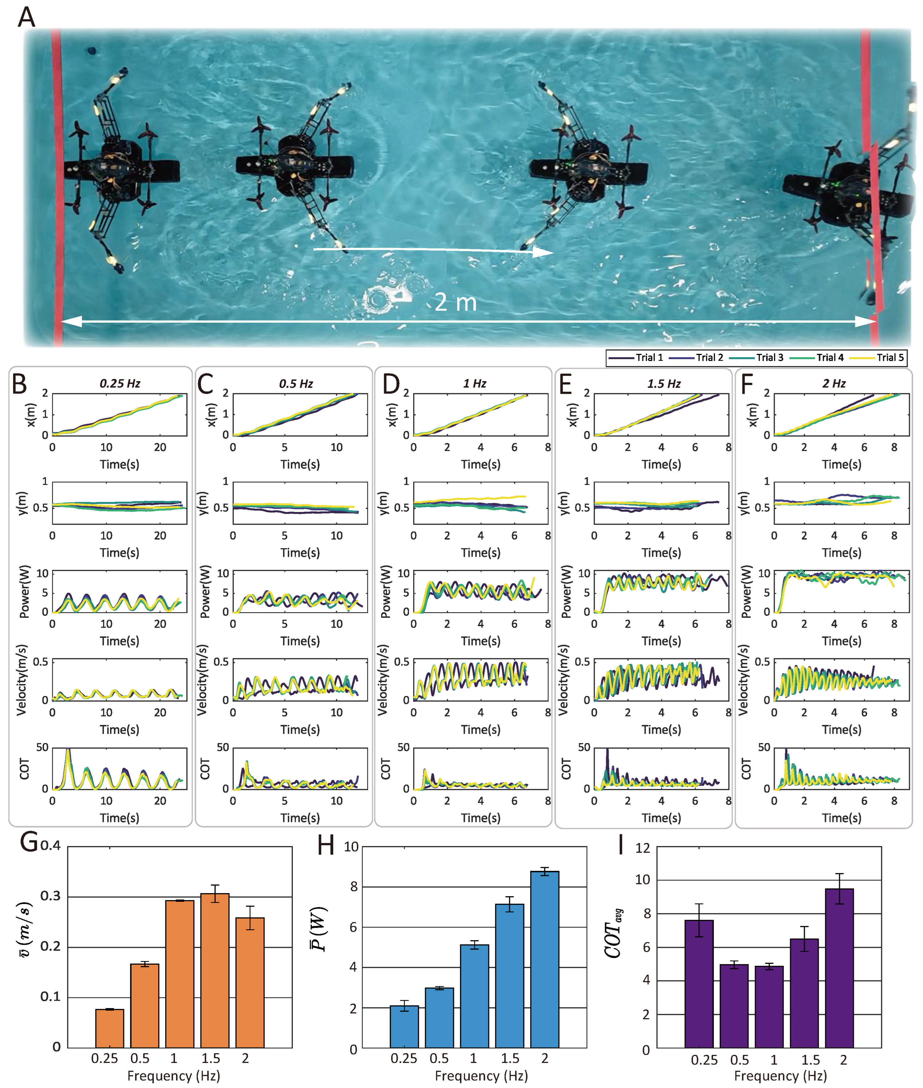
3.5. Aquatic Swimming Statistical Tests
3.5.1. Speed, Power, and Cost of Transport (COT) Influenced by Paddling Frequency
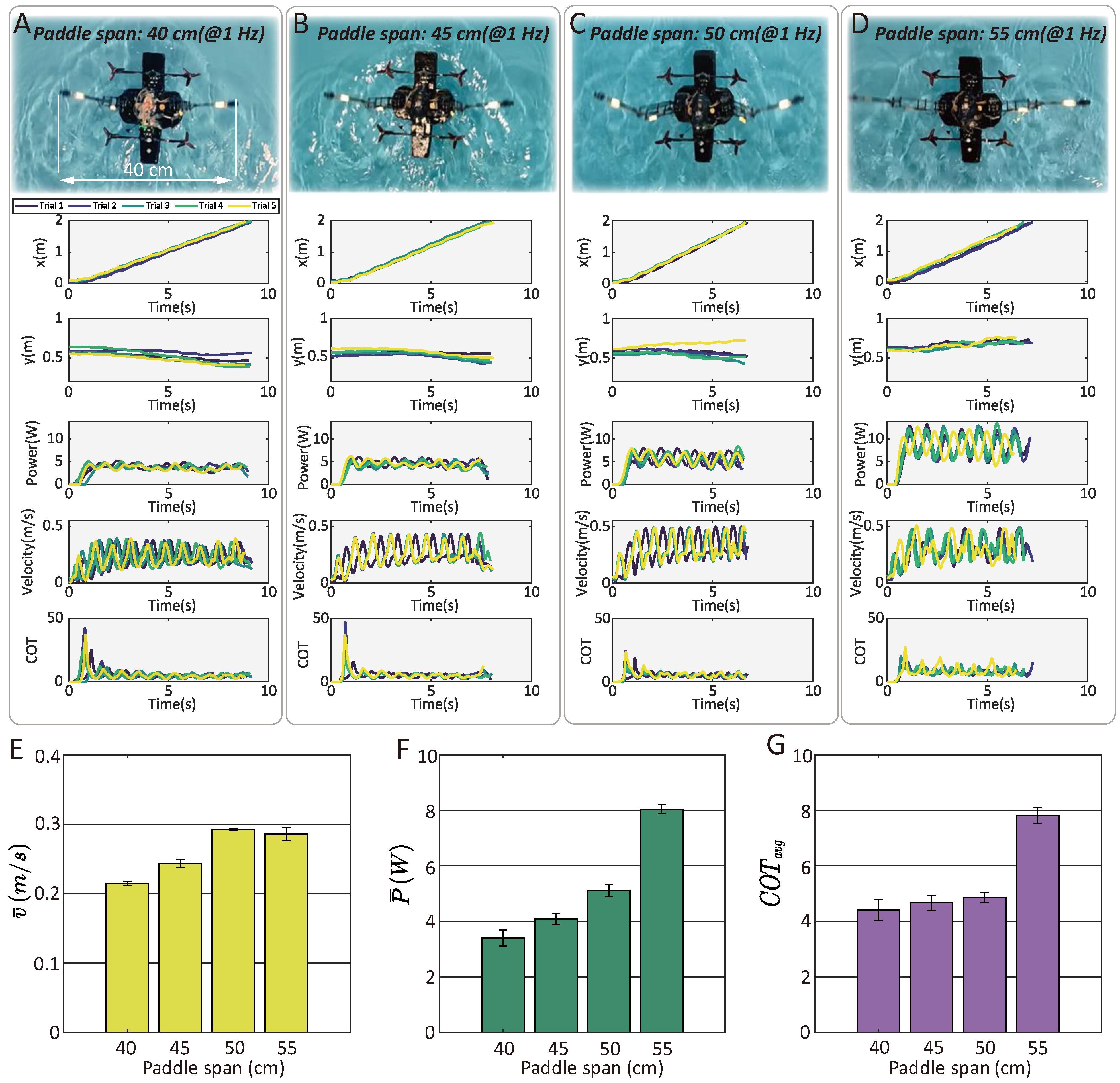
3.5.2. Speed, Power, and Cost of Transport (COT) Influenced by Paddling Span
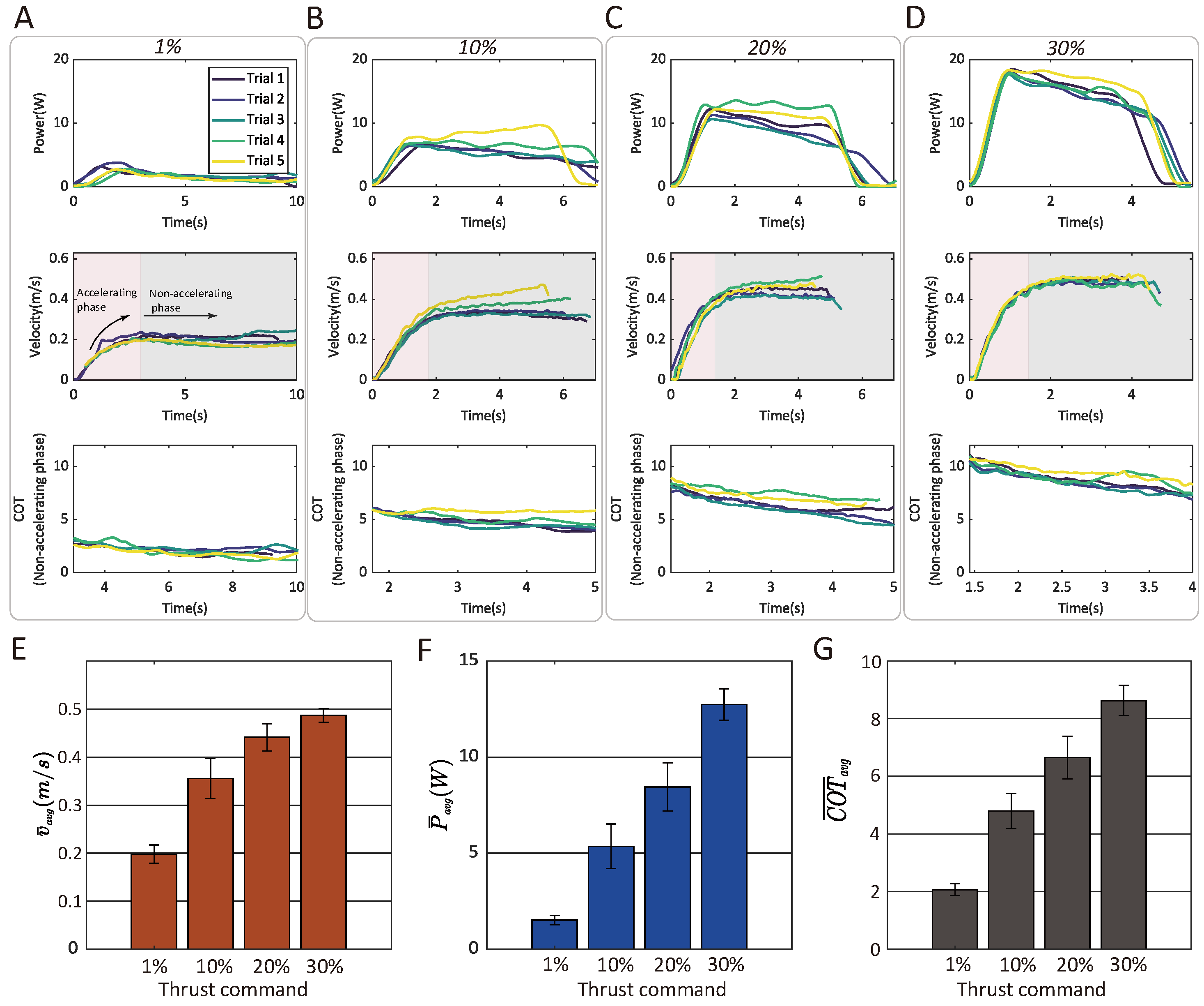
3.5.3. Correlation Between the Air-Propelled Drifting Speed, Power, and COT and Thrust Command
3.6. Jumping Assistive Flight
4. Discussion
- Leg unit: crawling, jumping, paddling, and balanced wheeling (four modes).
- Flight unit: jumping, flight, drifting, and tricycle/balanced wheeling (five modes).
Supplementary Materials
Author Contributions
Funding
Data Availability Statement
Acknowledgments
Conflicts of Interest
References
- Garthe, S.; Guse, N.; Montevecchi, W.A.; Rail, J.-F.; Grégoire, F. The daily catch: Flight altitude and diving behavior of northern gannets feeding on Atlantic mackerel. J. Sea Res. 2014, 85, 456–462. [Google Scholar] [CrossRef]
- Davenport, J. How and why do flying fish fly? Rev. Fish Biol. Fish. 1994, 4, 184–214. [Google Scholar] [CrossRef]
- Pan, Y.; Tang, G.; Liu, S.; Mei, D.; He, L.; Zhu, S.; Wang, Y. Tumro: A Tunable Multimodal Wheeled Jumping Robot Based on the Bionic Mechanism of Jumping Beetles. Adv. Intell. Syst. 2024, 6, 2400024. [Google Scholar] [CrossRef]
- Spiegel, S.; Sun, J.; Zhao, J. A shape-changing wheeling and jumping robot using tensegrity wheels and bistable mechanism. IEEE/ASME Trans. Mechatron. 2023, 28, 2073–2082. [Google Scholar] [CrossRef]
- Misu, K.; Yoshii, A.; Mochiyama, H. A compact wheeled robot that can jump while rolling. In Proceedings of the 2018 IEEE/RSJ International Conference on Intelligent Robots and Systems (IROS), Madrid, Spain, 1–5 October 2018; IEEE: Piscataway, NJ, USA, 2018; pp. 7507–7512. Available online: https://ieeexplore.ieee.org/abstract/document/8593895/ (accessed on 28 March 2025).
- Lambrecht, B.G.; Horchler, A.D.; Quinn, R.D. A small, insect-inspired robot that runs and jumps. In Proceedings of the 2005 IEEE International Conference on Robotics and Automation, Barcelona, Spain, 18–22 April 2005; IEEE: Piscataway, NJ, USA, 2005; pp. 1240–1245. Available online: https://ieeexplore.ieee.org/abstract/document/1570285/ (accessed on 28 March 2025).
- Jung, G.-P.; Casarez, C.S.; Lee, J.; Baek, S.-M.; Yim, S.-J.; Chae, S.-H.; Fearing, R.S.; Cho, K.-J. JumpRoACH: A trajectory-adjustable integrated jumping–crawling robot. IEEE/ASME Trans. Mechatron. 2019, 24, 947–958. [Google Scholar] [CrossRef]
- Chae, S.-H.; Baek, S.-M.; Lee, J.; Cho, K.-J. Agile and energy-efficient jumping–crawling robot through rapid transition of locomotion and enhanced jumping height adjustment. IEEE/ASME Trans. Mechatron. 2022, 27, 5890–5901. [Google Scholar] [CrossRef]
- Woodward, M.A.; Sitti, M. MultiMo-Bat: A biologically inspired integrated jumping-gliding robot. Int. J. Robot. Res. 2014, 33, 1511–1529. [Google Scholar] [CrossRef]
- Baek, S.-M.; Yim, S.; Chae, S.-H.; Lee, D.-Y.; Cho, K.-J. Ladybird beetle-inspired compliant origami. Sci. Robot. 2020, 5, eaaz6262. [Google Scholar] [CrossRef]
- Zufferey, R.; Ancel, A.O.; Farinha, A.; Siddall, R.; Armanini, S.F.; Nasr, M.; Brahmal, R.V.; Kennedy, G.; Kovac, M. Consecutive aquatic jump-gliding with water-reactive fuel. Sci. Robot. 2019, 4, eaax7330. [Google Scholar] [CrossRef]
- Kovač, M.; Fauria, O.; Zufferey, J.-C.; Floreano, D. The EPFL jumpglider: A hybrid jumping and gliding robot with rigid or folding wings. In Proceedings of the 2011 IEEE International Conference on Robotics and Biomimetics, Karon Beach, Thailand, 7–11 December 2011; IEEE: Piscataway, NJ, USA, 2011; pp. 1503–1508. Available online: https://ieeexplore.ieee.org/abstract/document/6181502/?casa_token=uG_IkmtUOE4AAAAA:9_kf5Enc4pZ_uKIx18SsJ-27UIXHLFSSFPqENNfpuRBYSa9U6CEfirUDR4DyE3cRWGlF2WLq8g (accessed on 18 October 2024).
- Vidyasagar, A.; Zufferey, J.-C.; Floreano, D.; Kovač, M. Performance analysis of jump-gliding locomotion for miniature robotics. Bioinspir. Biomim. 2015, 10, 025006. [Google Scholar] [CrossRef]
- Armour, R.; Paskins, K.; Bowyer, A.; Vincent, J.; Megill, W. Jumping robots: A biomimetic solution to locomotion across rough terrain. Bioinspir. Biomim. 2007, 2, S65. [Google Scholar] [CrossRef] [PubMed]
- Tang, L.; Li, Y.; Li, B. Moobot: A miniature origami omnidirectional jumping robot with high trajectory accuracy. IEEE Trans. Ind. Electron. 2023, 71, 6032–6040. Available online: https://ieeexplore.ieee.org/abstract/document/10191042/ (accessed on 18 December 2024). [CrossRef]
- Lachat, D.; Crespi, A.; Ijspeert, A.J. BoxyBot: A swimming and crawling fish robot controlled by a central pattern generator. In Proceedings of the First IEEE/RAS-EMBS International Conference on Biomedical Robotics and Biomechatronics, BioRob 2006, Pisa, Italy, 20–22 February 2006; IEEE: Piscataway, NJ, USA, 2006; pp. 643–648. Available online: https://ieeexplore.ieee.org/abstract/document/1639162/ (accessed on 28 March 2025).
- Crespi, A.; Lachat, D.; Pasquier, A.; Ijspeert, A.J. Controlling swimming and crawling in a fish robot using a central pattern generator. Auton. Robot. 2008, 25, 3–13. [Google Scholar] [CrossRef]
- Crespi, A.; Badertscher, A.; Guignard, A.; Ijspeert, A.J. AmphiBot I: An amphibious snake-like robot. Robot. Auton. Syst. 2005, 50, 163–175. [Google Scholar] [CrossRef]
- Crespi, A.; Ijspeert, A.J. AmphiBot II: An amphibious snake robot that crawls and swims using a central pattern generator. In Proceedings of the 9th International Conference on Climbing and Walking Robots (CLAWAR 2006), Brussels, Belgium, 1 September 2006; pp. 19–27. Available online: https://infoscience.epfl.ch/bitstreams/351631ef-02c9-4737-8fd8-f474268d7320/download (accessed on 28 March 2025).
- Crespi, A.; Ijspeert, A.J. Online optimization of swimming and crawling in an amphibious snake robot. IEEE Trans. Robot. 2008, 24, 75–87. [Google Scholar] [CrossRef]
- Karakasiliotis, K.; Thandiackal, R.; Melo, K.; Horvat, T.; Mahabadi, N.K.; Tsitkov, S.; Cabelguen, J.M.; Ijspeert, A.J. From cineradiography to biorobots: An approach for designing robots to emulate and study animal locomotion. J. R. Soc. Interface 2016, 13, 20151089. [Google Scholar] [CrossRef]
- Melo, K.; Horvat, T.; Ijspeert, A.J. Animal robots in the African wilderness: Lessons learned and outlook for field robotics. Sci. Robot. 2023, 8, eadd8662. [Google Scholar] [CrossRef]
- Baines, R.; Patiballa, S.K.; Booth, J.; Ramirez, L.; Sipple, T.; Garcia, A.; Fish, F.; Kramer-Bottiglio, R. Multi-environment robotic transitions through adaptive morphogenesis. Nature 2022, 610, 283–289. [Google Scholar] [CrossRef]
- Wu, M.; Xu, X.; Zhao, Q.; Afridi, W.H.; Hou, N.; Afridi, R.H.; Zheng, X.; Wang, C.; Xie, G. A Fully 3D-Printed Tortoise-Inspired Soft Robot with Terrains-Adaptive and Amphibious Landing Capabilities. Adv. Mater. Technol. 2022, 7, 2200536. [Google Scholar] [CrossRef]
- Xing, H.; Guo, S.; Shi, L.; Hou, X.; Liu, Y.; Liu, H.; Hu, Y.; Xia, D.; Li, Z. A novel small-scale turtle-inspired amphibious spherical robot. In Proceedings of the 2019 IEEE/RSJ International Conference on Intelligent Robots and Systems (IROS), Macau, China, 3–8 November 2019; IEEE: Piscataway, NJ, USA, 2019; pp. 1702–1707. Available online: https://ieeexplore.ieee.org/abstract/document/8968304/ (accessed on 28 March 2025).
- Sihite, E.; Kalantari, A.; Nemovi, R.; Ramezani, A.; Gharib, M. Multi-Modal Mobility Morphobot (M4) with appendage repurposing for locomotion plasticity enhancement. Nat. Commun. 2023, 14, 3323. [Google Scholar] [CrossRef]
- Meiri, N.; Zarrouk, D. Flying STAR, a Hybrid Crawling and Flying Sprawl Tuned Robot. In Proceedings of the 2019 International Conference on Robotics and Automation (ICRA), Montreal, QC, Canada, 20–24 May 2019; pp. 5302–5308. [Google Scholar] [CrossRef]
- Askari, M.; Benciolini, M.; Phan, H.-V.; Stewart, W.; Ijspeert, A.J.; Floreano, D. Crash-perching on vertical poles with a hugging-wing robot. Commun. Eng. 2024, 3, 98. [Google Scholar] [CrossRef]
- Daler, L.; Mintchev, S.; Stefanini, C.; Floreano, D. A bioinspired multi-modal flying and walking robot. Bioinspir. Biomim. 2015, 10, 016005. [Google Scholar] [CrossRef]
- Chen, Y.; Wang, H.; Helbling, E.F.; Jafferis, N.T.; Zufferey, R.; Ong, A.; Ma, K.; Gravish, N.; Chirarattananon, P.; Kovac, M.; et al. A biologically inspired, flapping-wing, hybrid aerial-aquatic microrobot. Sci. Robot. 2017, 2, eaao5619. [Google Scholar] [CrossRef]
- Li, L.; Wang, S.; Zhang, Y.; Song, S.; Wang, C.; Tan, S.; Zhao, W.; Wang, G.; Sun, W.; Yang, F.; et al. Aerial-aquatic robots capable of crossing the air-water boundary and hitchhiking on surfaces. Sci. Robot. 2022, 7, eabm6695. [Google Scholar] [CrossRef]
- Li, L.; Liu, W.; Tian, B.; Hu, P.; Gao, W.; Liu, Y.; Yang, F.; Duo, Y.; Cai, H.; Zhang, Y.; et al. An Aerial-Aquatic Hitchhiking Robot with Remora-Inspired Tactile Sensors and Thrust Vectoring Units. Adv. Intell. Syst. 2023, 2300381. [Google Scholar] [CrossRef]
- Tan, Y.H.; Siddall, R.; Kovac, M. Efficient aerial–aquatic locomotion with a single propulsion system. IEEE Robot. Autom. Lett. 2017, 2, 1304–1311. [Google Scholar] [CrossRef]
- Burrows, M.; Morris, O. Jumping and kicking in bush crickets. J. Exp. Biol. 2003, 206, 1035–1049. [Google Scholar] [CrossRef]
- Haldane, D.W.; Plecnik, M.M.; Yim, J.K.; Fearing, R.S. Robotic vertical jumping agility via series-elastic power modulation. Sci. Robot. 2016, 1, eaag2048. [Google Scholar] [CrossRef]
- Pace, C.M.; Gibb, A.C. Mudskipper pectoral fin kinematics in aquatic and terrestrial environments. J. Exp. Biol. 2009, 212, 2279–2286. [Google Scholar] [CrossRef]
- Blake, R.W. Hydrodynamics of swimming in the water boatman, Cenocorixa bifida. Can. J. Zool. 1986, 64, 1606–1613. [Google Scholar] [CrossRef]
- Controller Diagrams|PX4 Guide (Main). Available online: https://docs.px4.io/main/en/flight_stack/controller_diagrams.html (accessed on 2 April 2025).
- Kim, K.; Spieler, P.; Lupu, E.-S.; Ramezani, A.; Chung, S.-J. A bipedal walking robot that can fly, slackline, and skateboard. Sci. Robot. 2021, 6, eabf8136. [Google Scholar] [CrossRef]
- Shin, W.D.; Phan, H.-V.; Daley, M.A.; Ijspeert, A.J.; Floreano, D. Fast ground-to-air transition with avian-inspired multifunctional legs. Nature 2024, 636, 86–91. [Google Scholar] [CrossRef]
- Shin, W.D.; Park, J.; Park, H.-W. Development and experiments of a bio-inspired robot with multi-mode in aerial and terrestrial locomotion. Bioinspir. Biomim. 2019, 14, 056009. [Google Scholar] [CrossRef] [PubMed]
- Haldane, D.W.; Yim, J.K.; Fearing, R.S. Repetitive extreme-acceleration (14-g) spatial jumping with Salto-1P. In Proceedings of the 2017 IEEE/RSJ International Conference on Intelligent Robots and Systems (IROS), Vancouver, BC, Canada, 24–28 September 2017; IEEE: Piscataway, NJ, USA, 2017; pp. 3345–3351. Available online: https://ieeexplore.ieee.org/abstract/document/8206172/ (accessed on 23 March 2025).
- Kenneally, G.; De, A.; Koditschek, D.E. Design principles for a family of direct-drive legged robots. IEEE Robot. Autom. Lett. 2016, 1, 900–907. [Google Scholar] [CrossRef]
- Katz, B.; Di Carlo, J.; Kim, S. Mini cheetah: A platform for pushing the limits of dynamic quadruped control. In Proceedings of the 2019 International Conference on Robotics and Automation (ICRA), Montreal, QC, Canada, 20–24 May 2019; IEEE: Piscataway, NJ, USA, 2019; pp. 6295–6301. Available online: https://ieeexplore.ieee.org/abstract/document/8793865/ (accessed on 28 February 2025).
- De, A.; Koditschek, D.E. The Penn Jerboa: A Platform for Exploring Parallel Composition of Templates. arXiv 2016, arXiv:1502.05347. Available online: http://arxiv.org/abs/1502.05347 (accessed on 3 October 2023).
- Zaitsev, V.; Gvirsman, O.; Hanan, U.B.; Weiss, A.; Ayali, A.; Kosa, G. A locust-inspired miniature jumping robot. Bioinspir. Biomim. 2015, 10, 066012. [Google Scholar] [CrossRef]
- Lo, J.; Parslew, B. Characterising the take-off dynamics and energy efficiency in spring-driven jumping robots. Mech. Mach. Theory 2024, 199, 105688. [Google Scholar] [CrossRef]
- Kovac, M.; Fuchs, M.; Guignard, A.; Zufferey, J.-C.; Floreano, D. A miniature 7g jumping robot. In Proceedings of the 2008 IEEE International Conference on Robotics and Automation, Pasadena, CA, USA, 19–23 May 2008; IEEE: Piscataway, NJ, USA, 2008; pp. 373–378. Available online: https://ieeexplore.ieee.org/abstract/document/4543236/ (accessed on 2 October 2023).
- Zhao, J.; Xu, J.; Gao, B.; Xi, N.; Cintron, F.J.; Mutka, M.W.; Xiao, L. MSU jumper: A single-motor-actuated miniature steerable jumping robot. IEEE Trans. Robot. 2013, 29, 602–614. [Google Scholar] [CrossRef]
- Zhakypov, Z.; Mori, K.; Hosoda, K.; Paik, J. Designing minimal and scalable insect-inspired multi-locomotion millirobots. Nature 2019, 571, 381–386. [Google Scholar] [CrossRef] [PubMed]
- Scarfogliero, U.; Stefanini, C.; Dario, P. Design and development of the long-jumping “grillo” mini robot. In Proceedings of the 2007 IEEE International Conference on Robotics and Automation, Rome, Italy, 10–14 April 2007; IEEE: Piscataway, NJ, USA, 2007; pp. 467–472. Available online: https://ieeexplore.ieee.org/abstract/document/4209135/?casa_token=eWb2_4-jRKwAAAAA:ADN6pvvbBaHNay98uWZtJvTp_X_t2g9gawAV_PpNhBO5QFM2xOiEJ_tn_iLG0j5k8ZdTy7awMw (accessed on 18 October 2024).
- Van Den Berg, S.C.; Scharff, R.B.; Rusák, Z.; Wu, J. OpenFish: Biomimetic design of a soft robotic fish for high speed locomotion. HardwareX 2022, 12, e00320. [Google Scholar] [CrossRef]
- Katzschmann, R.K.; DelPreto, J.; MacCurdy, R.; Rus, D. Exploration of underwater life with an acoustically controlled soft robotic fish. Sci. Robot. 2018, 3, eaar3449. [Google Scholar] [CrossRef] [PubMed]
- Nguyen, D.Q.; Ho, V.A. Anguilliform Swimming Performance of an Eel-Inspired Soft Robot. Soft Robot. 2022, 9, 425–439. [Google Scholar] [CrossRef] [PubMed]
- Marchese, A.D.; Onal, C.D.; Rus, D. Autonomous Soft Robotic Fish Capable of Escape Maneuvers Using Fluidic Elastomer Actuators. Soft Robot. 2014, 1, 75–87. [Google Scholar] [CrossRef]
- Tang, Y.; Chi, Y.; Sun, J.; Huang, T.-H.; Maghsoudi, O.H.; Spence, A.; Zhao, J.; Su, H.; Yin, J. Leveraging elastic instabilities for amplified performance: Spine-inspired high-speed and high-force soft robots. Sci. Adv. 2020, 6, eaaz6912. [Google Scholar] [CrossRef]
- Tang, C.; Ma, W.; Li, B.; Jin, M.; Chen, H. Cephalopod-Inspired Swimming Robot Using Dielectric Elastomer Synthetic Jet Actuator. Adv. Eng. Mater. 2020, 22, 1901130. [Google Scholar] [CrossRef]
- Shintake, J.; Cacucciolo, V.; Shea, H.; Floreano, D. Soft Biomimetic Fish Robot Made of Dielectric Elastomer Actuators. Soft Robot. 2018, 5, 466–474. [Google Scholar] [CrossRef]
- Tang, Y.; Qin, L.; Li, X.; Chew, C.-M.; Zhu, J. A frog-inspired swimming robot based on dielectric elastomer actuators. In Proceedings of the 2017 IEEE/RSJ International Conference on Intelligent Robots and Systems (IROS), Vancouver, BC, Canada, 24–28 September 2017; pp. 2403–2408. [Google Scholar] [CrossRef]
- Li, T.; Li, G.; Liang, Y.; Cheng, T.; Dai, J.; Yang, X.; Liu, B.; Zeng, Z.; Huang, Z.; Luo, Y.; et al. Fast-moving soft electronic fish. Sci. Adv. 2017, 3, e1602045. [Google Scholar] [CrossRef]
- Li, G.; Chen, X.; Zhou, F.; Liang, Y.; Xiao, Y.; Cao, X.; Zhang, Z.; Zhang, M.; Wu, B.; Yin, S. Self-powered soft robot in the Mariana Trench. Nature 2021, 591, 66–71. [Google Scholar] [CrossRef]
- Christianson, C.; Goldberg, N.N.; Deheyn, D.D.; Cai, S.; Tolley, M.T. Translucent soft robots driven by frameless fluid electrode dielectric elastomer actuators. Sci. Robot. 2018, 3, eaat1893. [Google Scholar] [CrossRef]
- Bayat, B.; Crespi, A.; Ijspeert, A. Envirobot: A bio-inspired environmental monitoring platform. In Proceedings of the 2016 IEEE/OES Autonomous Underwater Vehicles (AUV), Tokyo, Japan, 6–9 November 2016; IEEE: Piscataway, NJ, USA, 2016; pp. 381–386. Available online: https://ieeexplore.ieee.org/abstract/document/7778700/ (accessed on 10 May 2025).
- Porez, M.; Boyer, F.; Ijspeert, A.J. Improved Lighthill fish swimming model for bio-inspired robots: Modeling, computational aspects and experimental comparisons. Int. J. Robot. Res. 2014, 33, 1322–1341. [Google Scholar] [CrossRef]
- Yan, J.H.; Zhang, X.B.; Zhao, J.; Liu, G.F.; Cai, H.G.; Pan, Q.M. A miniature surface tension-driven robot using spatially elliptical moving legs to mimic a water strider’s locomotion. Bioinspir. Biomim. 2015, 10, 046016. [Google Scholar] [CrossRef] [PubMed]
- Yan, J.; Yang, K.; Liu, G.; Zhao, J. Flexible driving mechanism inspired water strider robot walking on water surface. IEEE Access 2020, 8, 89643–89654. [Google Scholar] [CrossRef]
- Ozcan, O.; Wang, H.; Taylor, J.D.; Sitti, M. STRIDE II: A Water Strider-inspired Miniature Robot with Circular Footpads. Int. J. Adv. Robot. Syst. 2014, 11, 85. [Google Scholar] [CrossRef]
- Song, Y.S.; Sitti, M. Surface-tension-driven biologically inspired water strider robots: Theory and experiments. IEEE Trans. Robot. 2007, 23, 578–589. [Google Scholar] [CrossRef]
- Kim, D.; Gwon, M.; Kim, B.; Ortega-Jimenez, V.M.; Han, S.; Kang, D.; Bhamla, M.S.; Koh, J.-S. Design of a biologically inspired Water-Walking robot powered by artificial muscle. Micromachines 2022, 13, 627. [Google Scholar] [CrossRef]

| Environment | Functions | Method | Dedicated Scenarios |
|---|---|---|---|
| Terrestrial | Jumping | Leg synchronous extension while balanced by air thrust force | Overcoming large local obstacles |
| Crawling | Synchronous paddling-like pulling motion | Rough terrain (e.g., cobbles, sand, and grassland) | |
| Balanced wheeling | Balanced while using horizontal thrust force to drive passive wheels | To seamlessly initiate jumping | |
| Tricycle wheeling | Morphology transformation + Forward thrust propels passive wheels | Fast and efficient motion on flat terrain | |
| Object transfer | Synchronous paddling motion (low-frequency) | Delivery tasks of small-scale objects or when paths are blocked | |
| Aquatic | Synchronous paddling | Paddling motion | Delicate motions in aquatic regions |
| Air-propelled drifting | Forward air thrust force | Efficiency in aquatic regions | |
| Aerial | Quadcopter flight | Cascaded PID attitude control | Long-distance transportation |
| Parameters | a | b | c | d | e | l1 | l2 | l3 |
| Dimensions (m) | 0.014 | 0.02065 | 0.025 | 0.025 | 0.01245 | 0.12 | 0.175 | 0.160 |
| Settings | KP | KI | KD |
|---|---|---|---|
| Roll rate | 0.150 | 0.150 | 0.0020 |
| Pitch rate | 0.150 | 0.150 | 0.0020 |
| Yaw rate | 0.20 | 0.14 | - |
| Roll angle | 8 | - | - |
| Pitch angle | 6 | - | - |
| Yaw angle | 5 | - | - |
| Frequency (Hz) | Trial 1 | Trial 2 | Trial 3 | Trial 4 | Trial 5 | Mean | Standard Deviation | |
|---|---|---|---|---|---|---|---|---|
| Velocity (m/s) | 0.25 | 0.0770 | 0.0753 | 0.0760 | 0.0759 | 0.0791 | 0.0766 | 0.0015 |
| 0.5 | 0.1667 | 0.1617 | 0.1643 | 0.1753 | 0.1657 | 0.1667 | 0.0051 | |
| 1 | 0.2923 | 0.2929 | 0.2915 | 0.2917 | 0.2947 | 0.2926 | 0.0013 | |
| 1.5 | 0.2765 | 0.3067 | 0.3193 | 0.3144 | 0.3156 | 0.3065 | 0.0174 | |
| 2 | 0.2988 | 0.2441 | 0.2568 | 0.2415 | 0.2504 | 0.2583 | 0.0234 | |
| Power (W) | 0.25 | 2.4531 | 2.2898 | 1.9859 | 1.8187 | 1.9445 | 2.0984 | 0.2632 |
| 0.5 | 3.0156 | 3.0881 | 2.9325 | 2.9640 | 2.8877 | 2.9779 | 0.0774 | |
| 1 | 5.2520 | 4.8359 | 4.9783 | 5.2088 | 5.3426 | 5.1235 | 0.2095 | |
| 1.5 | 7.7084 | 7.2885 | 6.8253 | 7.0312 | 6.8162 | 7.1339 | 0.3744 | |
| 2 | 8.5947 | 8.9848 | 8.8965 | 8.8226 | 8.5199 | 8.7637 | 0.1987 | |
| COT | 0.25 | 8.8489 | 8.4463 | 7.2579 | 6.6556 | 6.8280 | 7.6073 | 0.9850 |
| 0.5 | 5.0246 | 5.3045 | 4.9575 | 4.6964 | 4.8405 | 4.9647 | 0.2272 | |
| 1 | 4.9907 | 4.5859 | 4.7436 | 4.9598 | 5.0354 | 4.8631 | 0.1914 | |
| 1.5 | 7.7434 | 6.6007 | 5.9373 | 6.2117 | 5.9989 | 6.4984 | 0.7428 | |
| 2 | 7.9894 | 10.2236 | 9.6225 | 10.1472 | 9.4507 | 9.4867 | 0.9001 |
| Span (cm) | Trial 1 | Trial 2 | Trial 3 | Trial 4 | Trial 5 | Mean | Standard Deviation | |
|---|---|---|---|---|---|---|---|---|
| Velocity (m/s) | 40 | 0.2109 | 0.2143 | 0.2135 | 0.2158 | 0.2191 | 0.2147 | 0.0030 |
| 45 | 0.2394 | 0.2503 | 0.2416 | 0.2488 | 0.2365 | 0.2433 | 0.0030 | |
| 50 | 0.2923 | 0.2929 | 0.2915 | 0.2917 | 0.2947 | 0.2926 | 0.0013 | |
| 55 | 0.2933 | 0.2691 | 0.2896 | 0.2882 | 0.2896 | 0.2860 | 0.0096 | |
| Power (W) | 40 | 3.5902 | 3.2897 | 2.9904 | 3.7332 | 3.4426 | 3.4092 | 0.2866 |
| 45 | 4.1841 | 4.1584 | 3.8069 | 3.9864 | 4.2929 | 4.0857 | 0.1907 | |
| 50 | 5.2520 | 4.8359 | 4.9783 | 5.2088 | 5.3426 | 5.1235 | 0.2095 | |
| 55 | 8.1304 | 7.9619 | 7.9591 | 8.2818 | 7.8744 | 8.0415 | 0.1633 | |
| COT | 40 | 4.7283 | 4.2638 | 3.8904 | 4.8050 | 4.3642 | 4.4104 | 0.3711 |
| 45 | 4.8545 | 4.6146 | 4.3766 | 4.4504 | 5.0418 | 4.6676 | 0.2782 | |
| 50 | 4.9907 | 4.5859 | 4.7436 | 4.9598 | 5.0354 | 4.8631 | 0.1914 | |
| 55 | 7.6995 | 8.2180 | 7.6336 | 7.9817 | 7.5524 | 7.8171 | 0.2763 |
| Thrust Command (%) | Trial 1 | Trial 2 | Trial 3 | Trial 4 | Trial 5 | Mean | Standard Deviation | |
|---|---|---|---|---|---|---|---|---|
| Velocity (m/s) | 40 | 0.2166 | 0.2036 | 0.2142 | 0.1801 | 0.1758 | 0.1981 | 0.0191 |
| 45 | 0.3227 | 0.3360 | 0.3234 | 0.3750 | 0.4201 | 0.3554 | 0.0420 | |
| 50 | 0.4468 | 0.4207 | 0.4064 | 0.4788 | 0.4530 | 0.4411 | 0.0284 | |
| 55 | 0.4960 | 0.4785 | 0.4833 | 0.4699 | 0.5051 | 0.4866 | 0.0140 | |
| Power (W) | 40 | 1.6699 | 1.7744 | 1.6407 | 1.2416 | 1.2584 | 1.5170 | 0.2488 |
| 45 | 4.3260 | 4.8352 | 4.6638 | 5.7431 | 7.2159 | 5.3568 | 1.1641 | |
| 50 | 8.5736 | 7.4197 | 7.1378 | 10.2607 | 8.8451 | 8.4474 | 1.2483 | |
| 55 | 12.7753 | 12.0593 | 12.2610 | 12.4449 | 14.1319 | 12.7345 | 0.8244 | |
| COT(non-accelerating phase) | 40 | 2.0079 | 2.2905 | 2.2909 | 1.9009 | 1.8493 | 2.0679 | 0.2113 |
| 45 | 4.4080 | 4.5092 | 4.3264 | 4.9282 | 5.8075 | 4.7959 | 0.6111 | |
| 50 | 6.5132 | 6.1372 | 5.7991 | 7.5755 | 7.2102 | 6.6470 | 0.7376 | |
| 55 | 8.9585 | 8.1117 | 8.1481 | 8.5955 | 9.3282 | 8.6284 | 0.5238 |
| Prototype | Reused Structure | |
|---|---|---|
| Aerial Unit | Terrestrial Unit | |
| Leonardo [39] | Thruster/High/IV | Leg/High/III |
| M4 [26] | Thruster/High/III | Leg/High/IV; Wheel/High/IV |
| MultiMo-Bat [9] | Fixed wing/Low/I | Jumping linkage/Medium/II |
| EPFL RAVEN [40] | Fixed wing/low/I; Thruster/low/I | Leg/High/III |
| Flying STAR [27] | Thruster/Medium/II | Wheel/Low/I |
| UIUC flying squirrel [41] | Gliding membrane/Medium/II | Leg/High/III |
| This work | Thruster/High/V | Leg/High/IV |
Disclaimer/Publisher’s Note: The statements, opinions and data contained in all publications are solely those of the individual author(s) and contributor(s) and not of MDPI and/or the editor(s). MDPI and/or the editor(s) disclaim responsibility for any injury to people or property resulting from any ideas, methods, instructions or products referred to in the content. |
© 2025 by the authors. Licensee MDPI, Basel, Switzerland. This article is an open access article distributed under the terms and conditions of the Creative Commons Attribution (CC BY) license (https://creativecommons.org/licenses/by/4.0/).
Share and Cite
Sun, Z.; Li, Y.; Teng, L. A Bipedal Robotic Platform Leveraging Reconfigurable Locomotion Policies for Terrestrial, Aquatic, and Aerial Mobility. Biomimetics 2025, 10, 374. https://doi.org/10.3390/biomimetics10060374
Sun Z, Li Y, Teng L. A Bipedal Robotic Platform Leveraging Reconfigurable Locomotion Policies for Terrestrial, Aquatic, and Aerial Mobility. Biomimetics. 2025; 10(6):374. https://doi.org/10.3390/biomimetics10060374
Chicago/Turabian StyleSun, Zijie, Yangmin Li, and Long Teng. 2025. "A Bipedal Robotic Platform Leveraging Reconfigurable Locomotion Policies for Terrestrial, Aquatic, and Aerial Mobility" Biomimetics 10, no. 6: 374. https://doi.org/10.3390/biomimetics10060374
APA StyleSun, Z., Li, Y., & Teng, L. (2025). A Bipedal Robotic Platform Leveraging Reconfigurable Locomotion Policies for Terrestrial, Aquatic, and Aerial Mobility. Biomimetics, 10(6), 374. https://doi.org/10.3390/biomimetics10060374