1. Introduction
In recent years, increasing attention has been given to utilizing captured human motion data to simplify the complex process of robot motion programming and learning [
1,
2,
3,
4]. Motion imitation not only enables robots to learn how to perform tasks by observing human movements but also expands the possibilities for enhancing the responsiveness and autonomy of humanoid robots [
1,
5,
6]. While previous studies have made significant progress in this field [
7,
8], achieving efficient and precise motion imitation remains a challenging problem [
9]. The core challenges in the context of multi-robot simultaneous motion imitation are twofold: (1) Existing retargeting methods struggle to simultaneously achieve geometric configuration similarity and precise end-effector position tracking. (2) Motion imitation relies on pose estimation, and traditional multi-person pose estimation often requires multiple motion capture devices, leading to data synchronization issues and increased system complexity. Moreover, these methods typically lack the generalization capability to accommodate different imitation subjects.
In the field of motion imitation, there are two main approaches: learning-based methods and model-based methods. In the domain of animation, reinforcement learning (RL) has been applied to generate complex human motions and perform various tasks. By using RL to train virtual character controllers, these motions can be replicated while exhibiting distinctive styles [
10,
11], scalability [
12,
13,
14], and reusability [
15,
16]. In the context of full-sized humanoid robots, some studies [
17,
18] have employed imitation learning to transfer human-like styles to controllers. However, precise tracking of human movements remains a significant challenge, primarily due to numerous discrepancies between simulation and the real world. These discrepancies include parameter mismatches and hardware limitations, such as those related to torque and joint constraints. Cheng et al. [
19] utilized animation datasets in conjunction with RL-driven techniques to achieve upper-body motion imitation, enabling actions such as handshakes, boxing punches, and dancing. However, their method supports only a single robot, and an increase in the number of imitation targets leads to greater training complexity. Additionally, it cannot track the end-effector position, which limits its ability to perform precise tasks.
Model-based approaches can be subdivided into Cartesian-space-based motion mapping and joint-space-based motion mapping. In Cartesian-space-based motion imitation, the goal for the upper body is to track the end-effector pose of the demonstrator’s hands. J. Koenemann et al. [
20] proposed a method based on inverse kinematics (IK) to imitate human hand and foot positions while ensuring stability through a balancing controller. M. Arduengo et al. [
21] utilized a quadratic programming (QP) controller for solving inverse kinematics and introduced a variable admittance controller to ensure safety during imitation and interaction.
Their approach was validated through multiple experiments on the TIAGo robot. The advantage of this approach lies in its intuitive task execution. However, it requires obtaining the demonstrator’s end-effector positions and poses, which imposes higher demands on pose estimation. Additionally, it cannot guarantee consistent arm configurations during the imitation process, which makes it challenging to meet obstacle avoidance requirements during motion.
In joint space-based motion imitation, the goal is to track the movement of each joint in the demonstrator’s arms. L. Penco et al. [
22] proposed a direct joint angle retargeting method that reduces computational complexity, and they validated it through multiple experiments on the iCub robot. In work by Zhang et al. [
23], a novel analytical method was introduced, which geometrically computes the joint angles of a human skeletal model based on the construction of 3D keypoints using link vectors and virtual joints. These angles are then mapped to the humanoid robot Nao. However, since this method was specifically designed for the Nao robot, which lacks an external–internal rotation joint in the shoulder, the algorithm cannot compute the corresponding shoulder rotation angles of the human, making it impossible for the robot to accurately imitate human motions. The advantage of this method lies in its high motion similarity and the ability to maintain consistent arm configurations, which enables obstacle avoidance during the imitation process. However, it cannot ensure accurate tracking of the end-effector position during task execution, making it difficult to perform operational tasks.
One of the key challenges in humanoid robotic arm motion imitation is ensuring both kinematic consistency and precise end-effector tracking. Although previous studies have explored human-to-humanoid retargeting, they have yet to effectively address this issue. To tackle this challenge, we propose an improved retargeting algorithm. Specifically, we first establish a geometric model of the human arm and solve for joint angles using inverse kinematics. These joint angles are then used as the initial conditions for a quadratic programming-based optimization in Cartesian space, ensuring that the final solution satisfies both joint-space constraints and end-effector tracking accuracy.
The advantages of multi-robot collaborative task execution lie in task parallelism and enhanced adaptability, enabling significant improvements in efficiency and fault tolerance [
24,
25]. In collaborative tasks requiring high precision and adaptability, a key challenge is the real-time correction of robot actions. Recent studies have shown that providing robots with real-time feedback similar to human interaction can improve their performance and safety across various application scenarios [
26]. One critical technology in this context is human posture estimation. Conventional multi-person pose estimation typically relies on multiple motion capture devices, which increases system complexity and introduces issues such as data asynchrony [
4,
27]. Moreover, different imitation targets require generalized mapping algorithms capable of handling diverse motion patterns [
28,
29].
With regard to posture estimation, a number of methodologies have been proposed in recent times [
30,
31,
32], based on different camera devices, functional principles, and performance. Researchers have obtained new results using a monocular camera [
33] or multiple synchronized cameras [
34], but the inference time in real-time applications has not been considered in these works. Hwang Y. et al. [
35] developed a posture monitoring method that combines information obtained from a monocular camera and the robot, enabling real-time upper limb posture estimation without the need for a training process. In the field of multi-person pose estimation, OpenPose [
36] provides real-time 2D multi-person keypoint detection with inference time superior to previous methods, while maintaining high-quality results. However, due to its nature as a heat map-based approach, the inference speed may be reduced, and residual errors may occur. William McNally et al. [
37] proposed a new method for multi-person 2D pose estimation that can simultaneously detect keypoint objects and human pose objects. The proposed method performs significantly faster and more accurately on the Microsoft COCO Keypoints benchmark. Although this method achieves good results in 2D human pose estimation, it does not consider extending it to 3D pose estimation.
Another critical challenge in multi-humanoid synchronized imitation is real-time, efficient multi-person 3D pose estimation. To enable humanoid robots not only to perform tasks independently but also to collaborate on complex tasks, we integrate 2D pose estimation with depth information and propose an efficient multi-person 3D pose estimation method. This approach relies solely on a single RGB-D camera to capture and estimate human motion in real time, reducing system complexity while enhancing efficiency.
In summary, we present a comprehensive real-time multi-humanoid robotic arm motion imitation system. By utilizing our improved retargeting algorithm, multiple robots can more accurately and dynamically mimic human arm movements. Additionally, by integrating multi-person pose estimation, the system enables simultaneous imitation and task collaboration among multiple robots. The main contributions of this work include the following:
- (1)
An improved retargeting algorithm that ensures consistency in the arm’s geometric configuration and precise end-effector tracking in robotic arm motion imitation.
- (2)
An efficient multi-person 3D pose estimation method, which ensures the system maintains real-time performance and does not significantly increase computational load as the number of detected objects grows.
- (3)
Experimental validation on a self-developed bipedal humanoid robot platform, demonstrating successful arm motion imitation, task execution, and multi-robot collaboration, thereby verifying the effectiveness and generalizability of the proposed approach.
2. Method
2.1. Design of Motion Imitation System
Figure 1 depicts the robot arm motion imitation system created in this paper. This hardware system is comprised of four distinct parts: the visual capture system, the upper processor, the lower processor, and the mechanical movement system.
The motion capture system can utilize a standard RGB-D camera, and in this paper, the Intel D435 depth camera is used. During the experiment, the camera is positioned directly in front of the subject at a height of approximately 1.5 m above the ground. The captured human body images are transmitted in real time to the upper-level processor via a USB interface.
The upper-level processor is a PC, specifically equipped with an Intel Core i7-12700H processor (2.30 GHz), 16 GB of RAM, and a GeForce RTX 3060 GPU (Intel, Santa Clara, CA, USA). During the experiment, the captured human image data are transmitted to the upper-level processor, where a pose estimation algorithm extracts 2D keypoint data for the human arm joints. Next, the depth information obtained from the camera is fused with the 2D keypoint data to generate 3D keypoints, which are then processed using a Kalman filter. Communication between the upper-level and lower-level processors is achieved through the ROS protocol, with the filtered keypoint data being sent to the lower-level processor.
The lower-level processor is an R86S host equipped with an N6005 CPU. Upon receiving the keypoint data via ROS, the initial joint angles of the arm are calculated based on the geometric model of the human arm, which serves as the initial reference for the end-effector position tracking optimization problem. Through iterative optimization, joint angles that satisfy both the geometric constraints and the end-effector position requirements are obtained. Finally, the target joint angles are transmitted to the mechanical motion system via the CAN bus, driving the motors of the robot arm joints.
The mechanical motion system comprises the robot’s dual arms, servo motors, and drivers. The humanoid robot employed in this study is a wholly self-designed robot, as illustrated in
Figure 2, featuring six degrees of freedom for each mechanical arm and a pair of end effectors. The arm joints include the shoulder flexion–extension joint, shoulder abduction–adduction joint, shoulder external–internal rotation joint, elbow flexion–extension joint, forearm pronation–supination joint, and wrist flexion–extension joint, which together allow for any posture in space (
Figure 3).
2.2. Multi-Person Pose Estimation
The human pose estimation technique utilizes a fusion of 2D pose estimation and camera depth information to obtain 3D information of human keypoints. The 2D pose estimation is implemented using the Keypoints And Poses As Objects (KAPAO) algorithm. The KAPAO algorithm employs a deep convolutional neural network
N, with an input consisting of a single RGB image
(where
h and
w represent the height and width of the image, respectively). The output comprises four types of output grids, denoted as
, where
[
37].
is the number of anchor channels and
is the number of output channels for each object.
Each grid utilizes different anchors, with smaller grids exhibiting larger receptive fields optimized for predicting large objects, while larger grids have smaller receptive fields better suited for predicting small objects [
38]. Through this set of grids, pose detection objects
and keypoint objects
are obtained. However, there may be redundancy between
and
, which is addressed by non-maximum suppression to obtain candidate pose objects
and keypoint matching objects
. Finally, a matching algorithm
is used to fuse
and
into the final pose estimation result.
For the calculation of keypoint coordinates, the output channel
contains the properties of the predicted object
, including objectness
(the probability that an object exists), intermediate bounding boxes
, object class scores
, and intermediate keypoints for human pose objects
[
37].
Following [
39], the intermediate bounding box
of an object is predicted in grid coordinates relative to the grid cell origin
using the following formula:
and represent the width and height of the anchor boxes, respectively. The value of s is determined based on the corresponding grid, taking values of 8, 16, 32, or 64. The symbol denotes the sigmoid function, and represents the intermediate values of the bounding boxes.
This detection strategy is extended to the keypoints of pose objects. The intermediate keypoints
for a pose object are predicted in grid coordinates and relative to the grid cell origin
using the following formula:
is used to constrain the possible values of the keypoints, and represents the intermediate values of the keypoints.
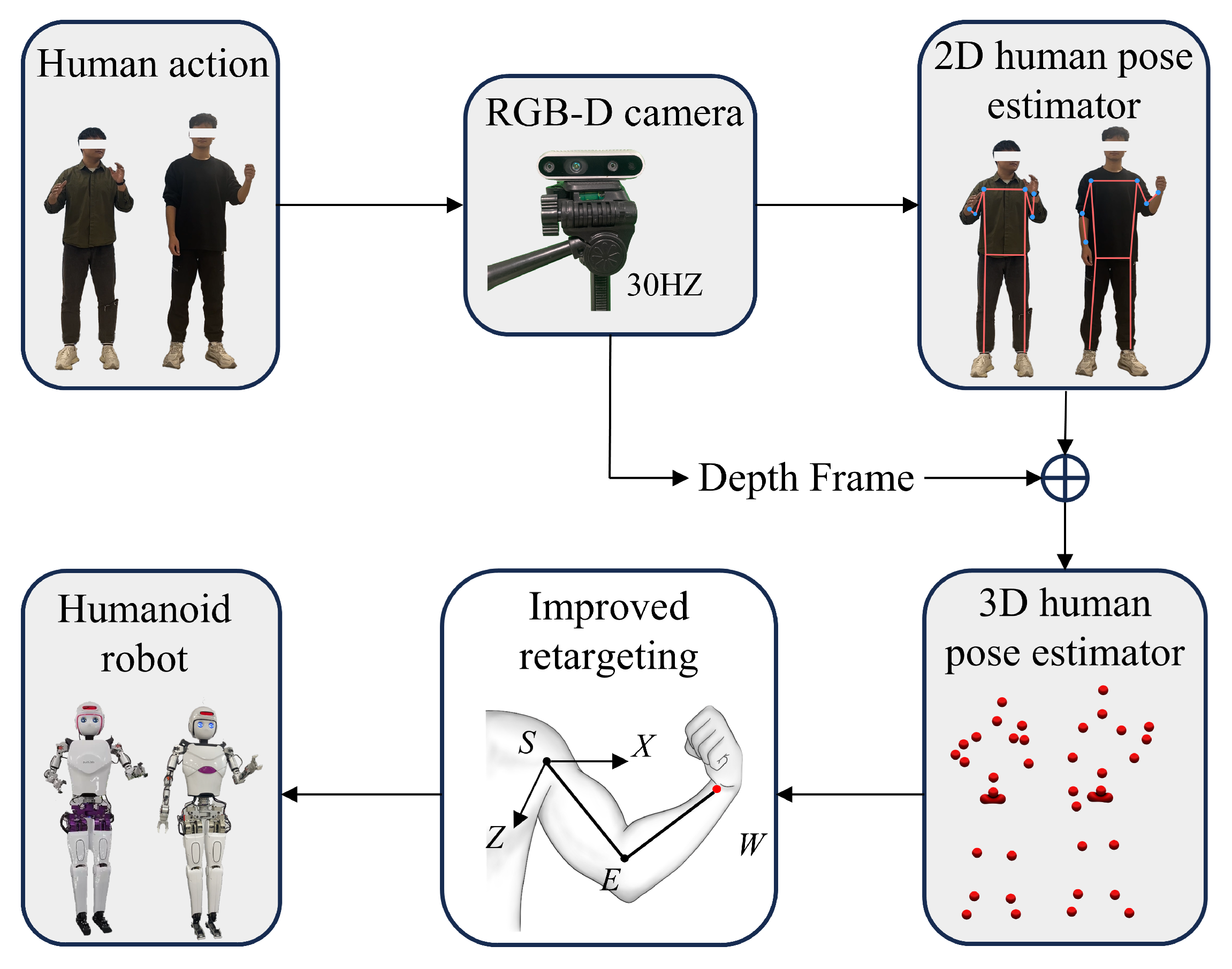
The standard output of KAPAO includes a set of 17 keypoints, which are used to construct a complete human skeleton model. A subset of these 17 keypoints is utilized in the system, corresponding to the 6 keypoints required for the upper body motion imitation on the robot through direct human pose mapping. It should be noted note that
Figure 4 illustrates that RGB and depth images are captured simultaneously in the current system. After obtaining the RGB frame, the image is passed to the KAPAO algorithm for processing. The algorithm then outputs a list of 17 2D keypoints, which are overlaid on the original image to outline the recognized human skeleton. Subsequently, using the depth information, these keypoints are transformed in depth space to obtain the 3D coordinates of the human keypoints. The 3D coordinates of three keypoints on the arm (shoulder, elbow, and wrist) are used as input for the improved retargeting method.
2.3. Improved Retargeting
2.3.1. Geometric Modeling of Human Arm Motion
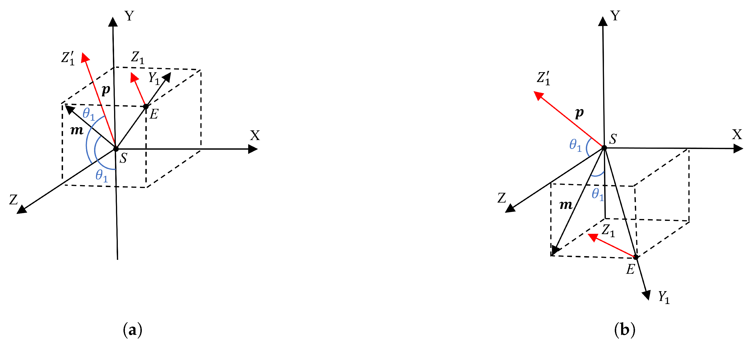
Since the shoulder and elbow primarily influence the movement of the arm, while the wrist mainly affects the hand’s motion, this study focuses on the geometric modeling of the shoulder and elbow joints. To clearly illustrate the modeling approach for the shoulder and elbow, the following presents the modeling process for the left arm.
Modeling of Human Shoulder Joints
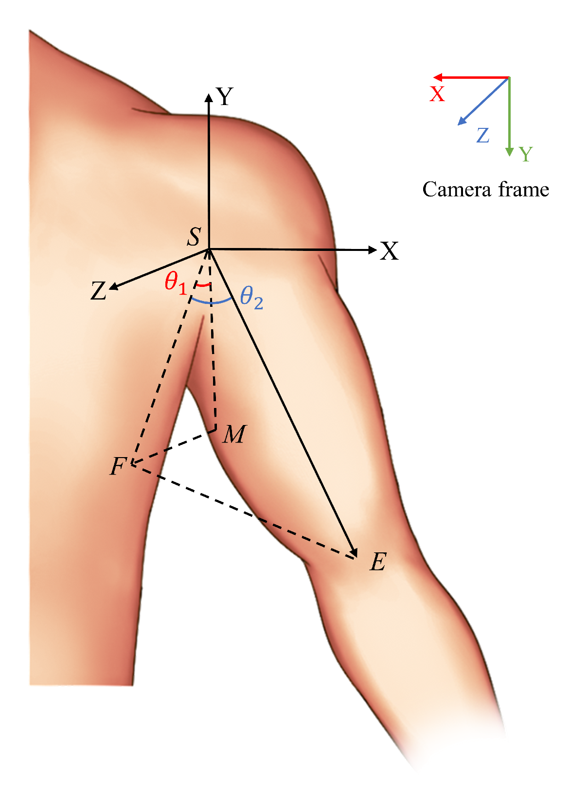
As illustrated in
Figure 3, the
S point represents the left arm shoulder joint, the
E point is the left arm elbow joint, and the
M point is a point along the Y axis with a length of
a.
According to the aforementioned definition, it can be demonstrated that . The coordinates of each point in the camera coordinate system are obtained through pose estimation as follows: , , . The coordinates of each point in the shoulder coordinate system, with the S point as the origin, are as follows: the coordinates of point S are , those of point E are , and those of point M are .
The projection of point E onto the plane is point F, with the coordinates . The projection of the vector onto the plane forms an angle with the negative direction of the Y axis, denoted as , where represents the shoulder flexion–extension joint angle. The angle between and its projection onto the plane is , denoted as , where represents the shoulder abduction–adduction joint angle.
In the context of geometric relationships, the value of
in
can be determined.
The direction of can be determined by examining . When , it indicates that the arm is swung forward. Conversely, when , it indicates that the arm is swung backward.
In
FSE, settle
:
where,
Modeling of the Human Elbow Joint
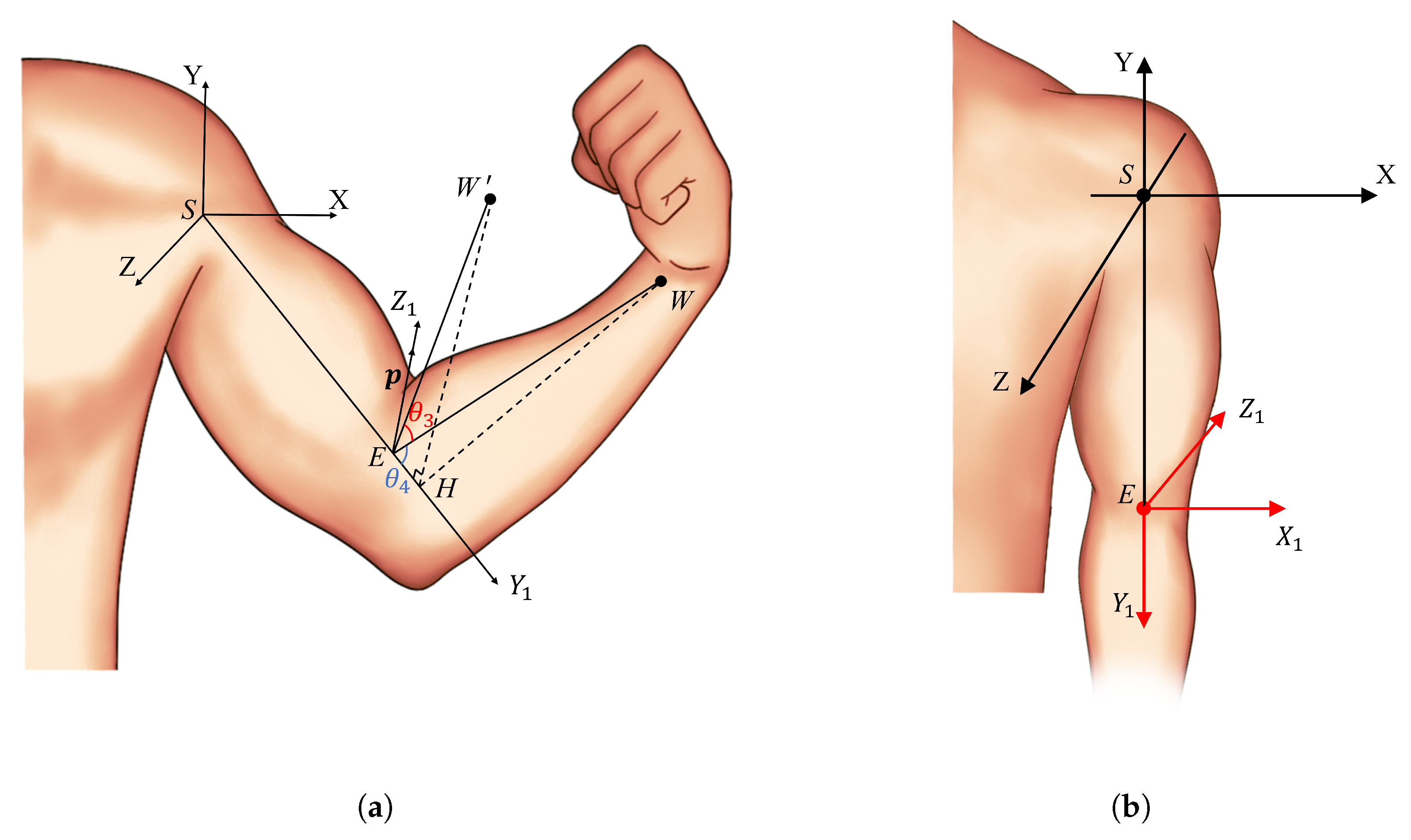
As shown in
Figure 5a,
W represents the actual position of the wrist, and
represents the assumed initial position of the wrist (where
). The angle
is defined as the angle between the vector
, which points from the elbow to the wrist, and its initial position vector
. The angle
is defined as the angle between vector
and the extended line of vector
.
When the wrist is in position
, the coordinate system of the elbow joint is denoted as
. Assuming the initial state of the arm is such that
,
,
, and
are all zero, the elbow joint coordinate system is as shown in
Figure 5b.
Using pose estimation, the absolute coordinates of points
S,
E, and
W in the camera coordinate system can be obtained as
,
, and
, respectively. The coordinates of the wrist
W in the shoulder-relative coordinate system are given by
. As shown in
Figure 5a, in the shoulder-relative coordinate system,
can be calculated using the dot product of vectors
and
The range of motion for the human elbow joint is
, where the coordinates of the vector
are
.
To solve for
, given the actual wrist position
W, we first need to compute
. As shown in
Figure 5a, the
axis is defined as the line always pointing from the shoulder joint to the elbow joint, meaning the
axis is along the vector
. Since
is already determined, regardless of changes in
, the angles between
,
, and
(
axis) will remain
. In other words, the line
, connecting the elbow and the wrist, rotates around the
axis, serving as the rotation axis, to form
.
Thus, by using , the vector can be obtained.
It is important to note that while the shoulder coordinate system remains fixed during arm movement, the elbow coordinate system changes its orientation, as shown in
Figure 6. During arm movement, the elbow coordinate system rotates to a new state. In
Figure 6, the direction of the
axis changes according to the value of
. The
axis represents the translation of the
axis from the elbow joint to the shoulder joint. The direction vector along the
axis is denoted as
, and
and
. Therefore,
. As shown in
Figure 6,
represents the direction of the
axis at the elbow joint when the wrist reaches position
. Given
and the direction vector
, which is parallel to
,
can be determined.
2.3.2. End-Effector Cartesian Position Tracking
After obtaining the arm joint angles through human geometric modeling, these angles can be directly used as target angles to control the movement of the robotic arm. While this method can mimic the motion, it does not achieve precise end-effector position tracking, which makes it difficult to perform tasks with high accuracy. To address this issue, we introduce end-effector position tracking constraints.
Considering the differences between the robot and human models, such as size, degrees of freedom, and physical parameters, the end-effector position may differ even if the joint angles are the same. To meet the Cartesian position tracking requirements during task execution, we use the change in the end-effector position (relative to the set initial arm position
) as the control target.
By monitoring the variation in the human arm’s end-effector position, precise tracking of the robot’s arm movement in task space is achieved. Based on this, the four joint angles obtained from the geometric modeling of the arm are used as initial conditions for the quadratic programming (QP) optimization. This method ensures that the geometric configuration of the robot arm remains consistent with that of the human arm while tracking the Cartesian target position.
The velocity mapping relationship between the joint space and task space can be obtained through differential kinematics.
Compute the Lagrangian function of the Equation (
18)
According to OSQP [
40], where the Hessian matrix
and the gradient vector
, the bounds are given by the following:
The overall algorithm flow is shown in Algorithm 1, ultimately solving for the arm joint angles
q that satisfy both the geometric configuration constraints and the end-effector position constraints.
| Algorithm 1 Fusion of geometric modeling and quadratic programming. |
Require: Reference joint angles obtained through geometric modeling Ensure: - 1:
Compute the initial position using forward kinematics: - 2:
Set simulation parameters: - 3:
Step size , number of steps - 4:
Previous position - 5:
Compute position increment: - 6:
for do - 7:
Step 1: Compute the updated Cartesian velocity and the Hessian matrix: - 8:
Step 2: Compute the joint velocities: - 9:
Step 3: Update the information: - 10:
Update joint positions: - 11:
Update the current Cartesian position: - 12:
end for - 13:
return q
|
3. Experiments
3.1. Single-Person Motion Imitation
In order to validate the accuracy of the human arm kinematic modeling and pose estimation algorithms, we first perform experimental verification through single-person motion imitation. The steps are as follows:
Step 1: Initialize the robot, ensuring all joints move to their zero positions.
Step 2: The demonstrators stand in front of the motion capture system (camera), ensuring that their bodies are within the camera’s field of view, and then activate the camera. The demonstrators begin performing the action, while the upper-level processor uses the pose estimation algorithm described in
Section 2.2 to obtain the keypoint coordinates of the shoulder, elbow, and wrist.
Step 3: In the lower-level processing, the keypoint coordinates of the shoulder, elbow, and wrist obtained from pose estimation are used to apply the human arm geometry model described in
Section 2.3.1. This allows for the calculation of the shoulder flexion–extension joint angle (
), shoulder abduction–adduction joint angle (
), elbow flexion–extension joint angle (
), and shoulder internal–external rotation joint angle (
). Then, through the end-effector position tracking described in
Section 2.3.2, the adjusted target joint angles
q for the robot are obtained.
Step 4: The computed target joint angles of the arm are directly transmitted to the robot, completing the motion imitation process.
As shown in
Figure 7, eight frames were selected from the continuous actions of the demonstrator to illustrate the process of the robot imitating human arm movements. The first and second sets demonstrate the robot imitating the human left arm movement, while the third and fourth sets showcase the robot imitating the human right arm movement. The final four sets present the robot simultaneously imitating the dual-arm actions.
By comparing the arm movements of the demonstrator and the robot, it is evident that the robot can accurately replicate human arm movements through the action imitation method. This validates that the pose estimation algorithm can precisely identify the three-dimensional coordinates of the keypoints of the human arm (shoulder, elbow, and wrist), and the improved redirection algorithm can correctly calculate the arm joint angles, enabling the robot to successfully replicate human arm motions.
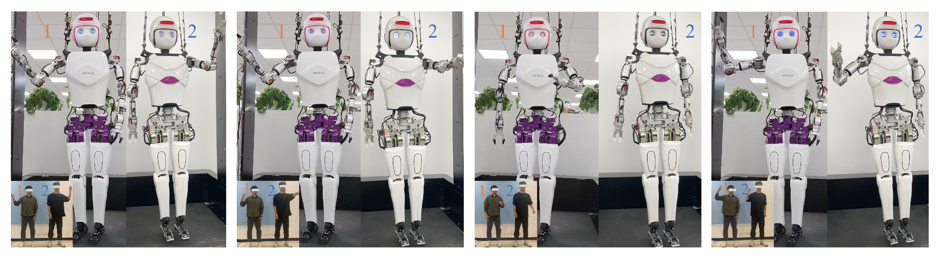
3.2. Multi-Person Motion Imitation
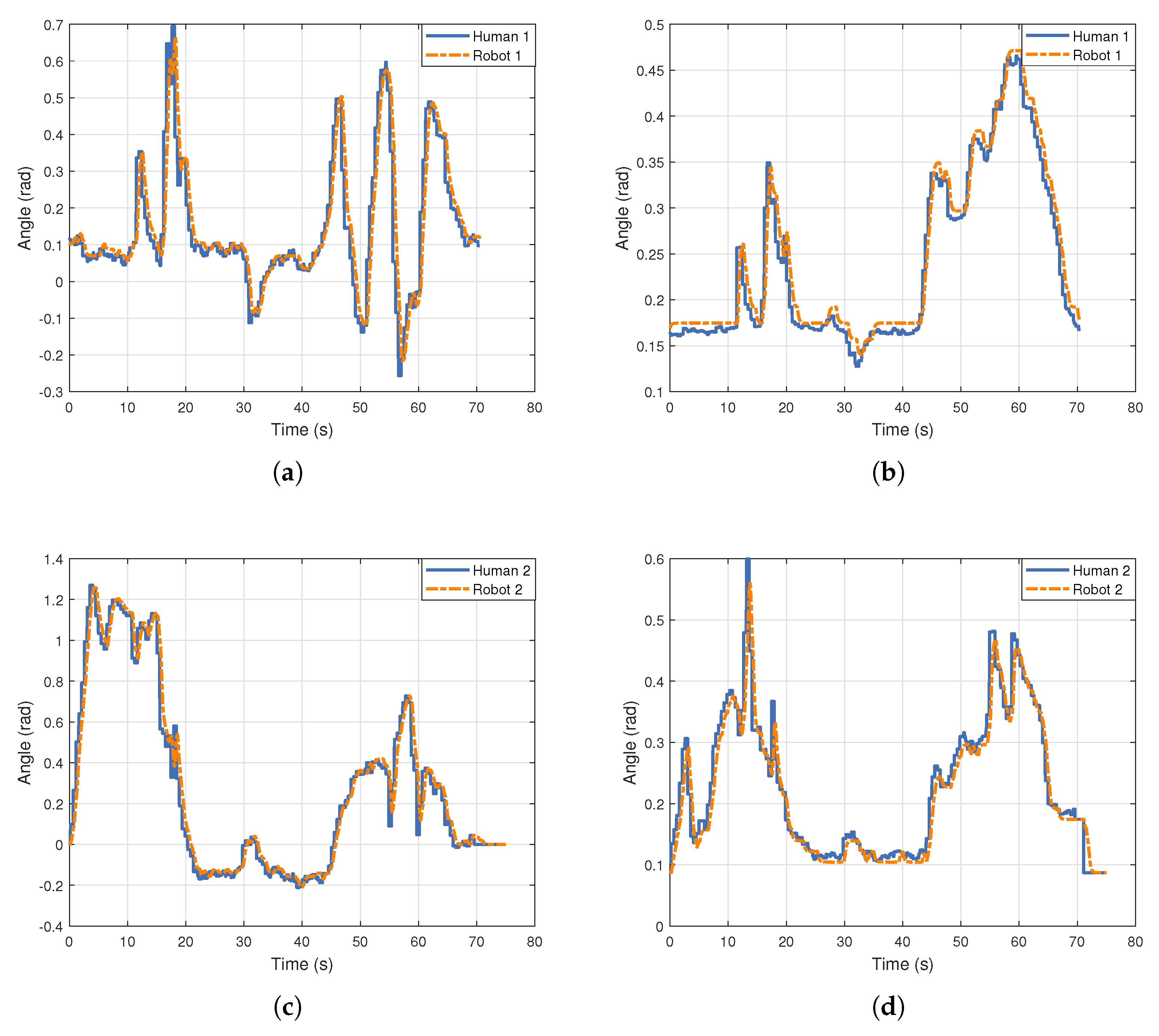
In the dual-person action imitation, although both robots have identical structural dimensions, the two demonstrators differ in height proportions and arm joint sizes.
Figure 8 illustrates four sets of different action states, each featuring distinct arm movements. Despite the physical differences between the two demonstrators, both robots can smoothly replicate the arm movements and end-effector positions of the demonstrators. This demonstrates the versatility of the improved redirection method and the real-time performance of multi-person pose estimation using a single camera.
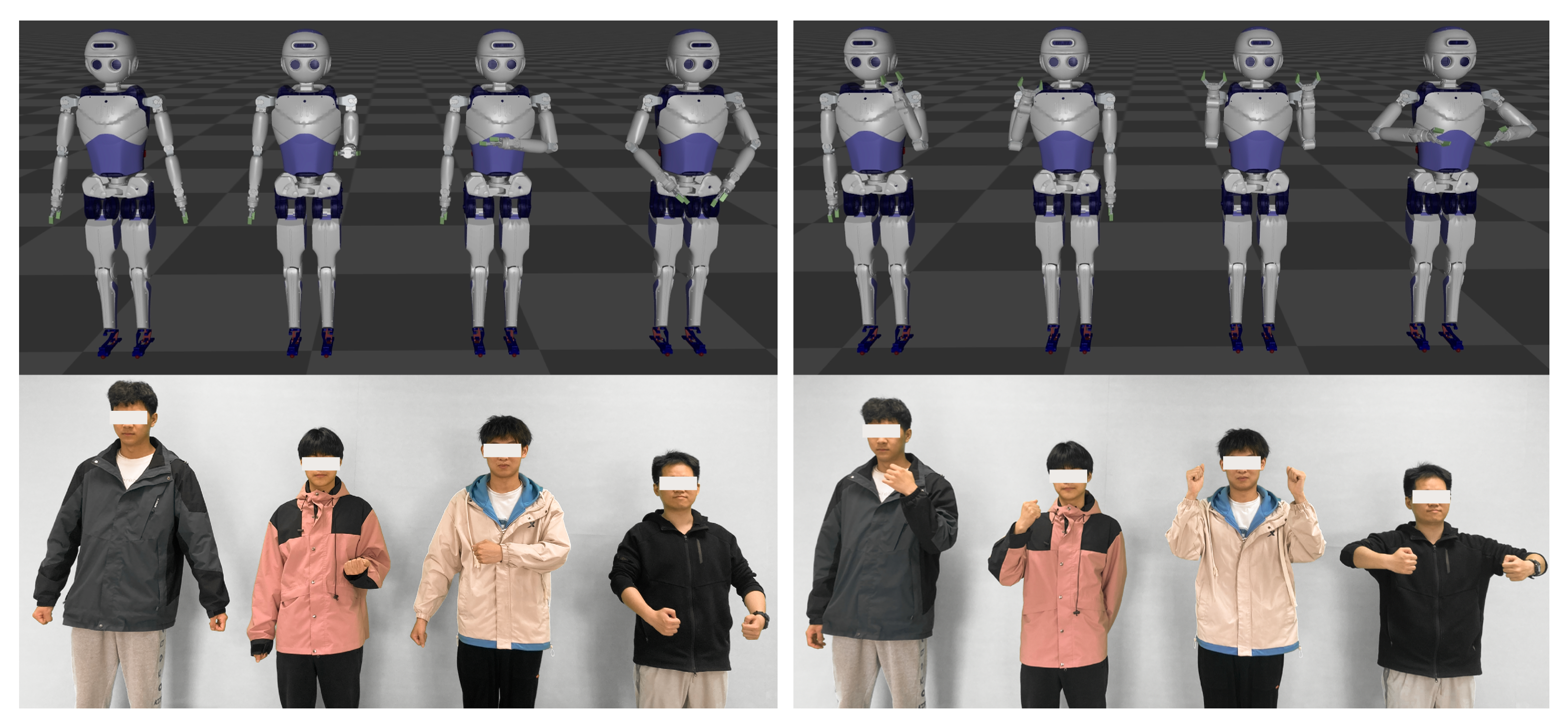
To evaluate the real-time performance of pose estimation as the number of detected objects increases, as well as the generalization ability of the action imitation algorithm, we conducted a multi-person action imitation experiment in a simulation environment. As shown in
Figure A1, four robot models were created in the Mujoco simulation environment. The movements of four demonstrators were captured by a motion capture system and used as input for pose estimation to generate keypoints for the arms. These keypoints were then processed using the improved redirection method to generate four sets of target arm joint angles, which drive the movement of the simulated robot joints. The joint control system operates with a 500 Hz PD position controller to ensure that its refresh rate matches the position control frequency of the physical robot, ensuring synchronization between the simulation and the actual control.
In the experiments, despite an increase in the number of demonstrators detected, the frame rate of multi-person pose estimation consistently remained at 30 FPS, with no significant impact on real-time performance. Furthermore, the improved redirection algorithm employed effectively ensured the similarity and generalization capability of motion imitation.
3.3. Task Operation
To evaluate the feasibility of our multi-person motion imitation system in real-world task scenarios, we selected four tasks: two single-arm imitation tasks (pouring and classification) and two dual-arm collaboration tasks (handover and transport). These tasks cover a range of scenarios that may occur in practical applications. To facilitate task execution, we used a handheld controller to operate the robot’s forearm pronation–supination joint, wrist flexion–extension joint, and the end effector’s gripper.
For the pouring task, as shown in
Figure 9, the robot needs to pour water from a bottle into a designated cup. This task presents certain risks for the robot and requires stability and accuracy.
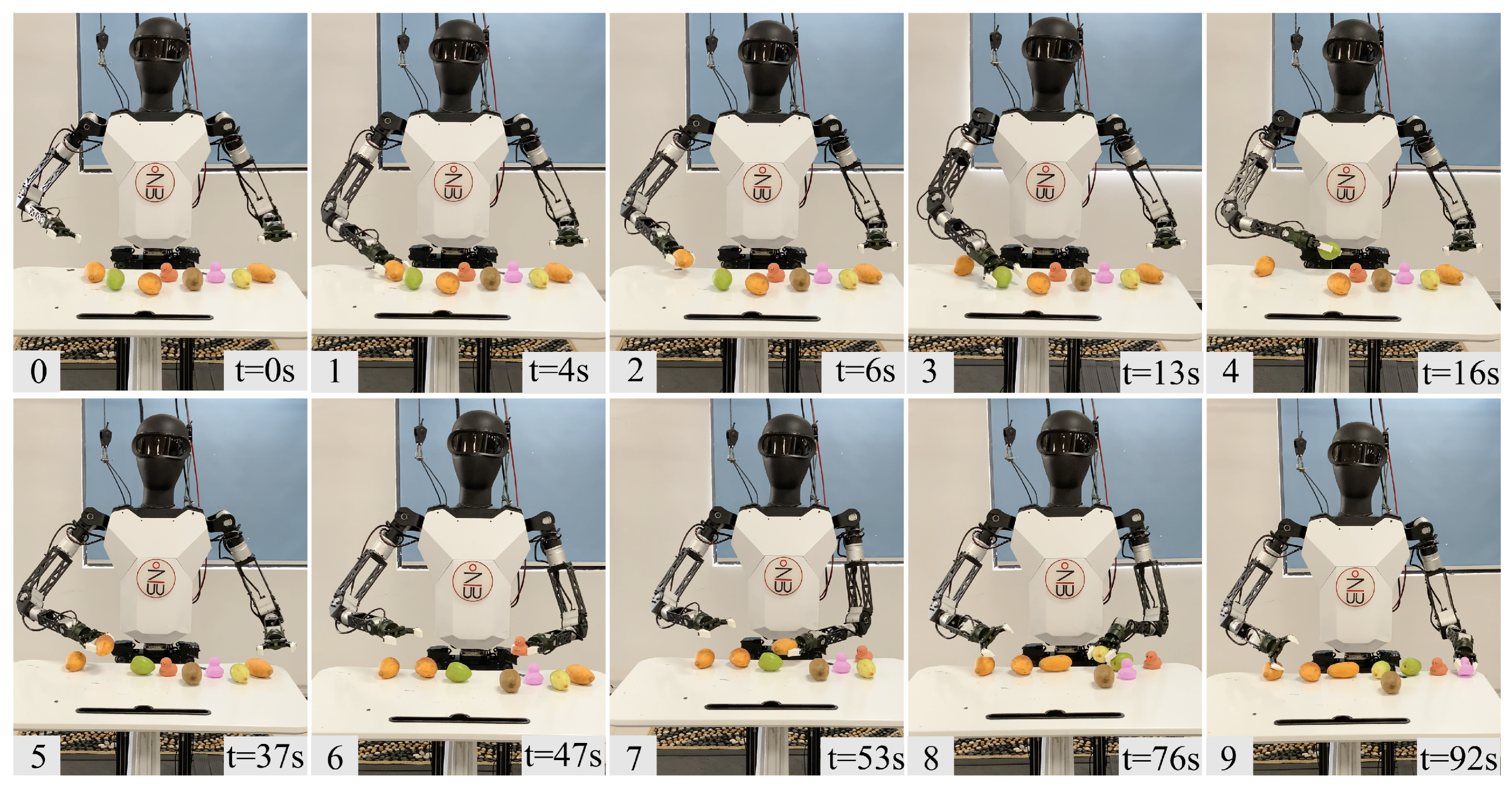
For the object classification task, also shown in
Figure 10, there are four types of items on the table: mangoes, dates, kiwis, and toys. The robot must move these items to their respective areas. This task is similar to everyday classification tasks and requires manipulation with both hands. Due to the restricted workspace of the single-arm robot, even the completion of the task would necessitate a longer time frame.
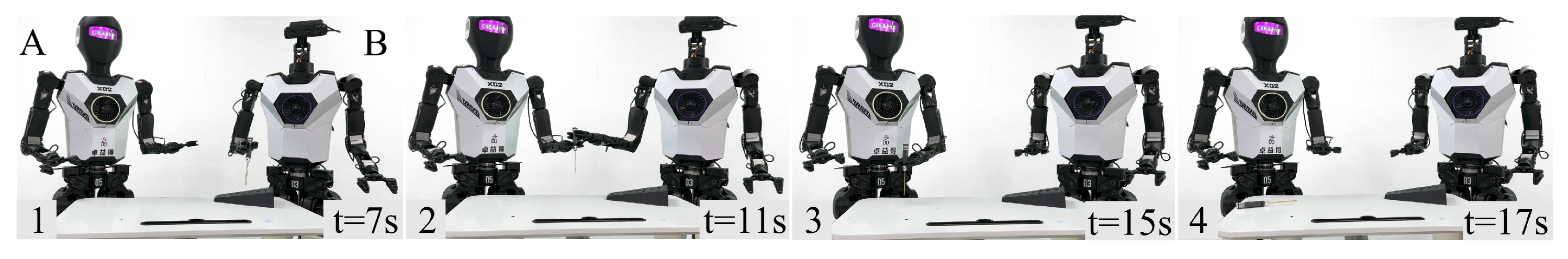
For the cooperative handover task, as shown in
Figure 11, a toolbox is placed on the table containing a hex screwdriver. Robot B needs to pick up the screwdriver from the toolbox and pass it to Robot A. Robot A then places the screwdriver onto the table. This task requires mutual collaboration between the robots.
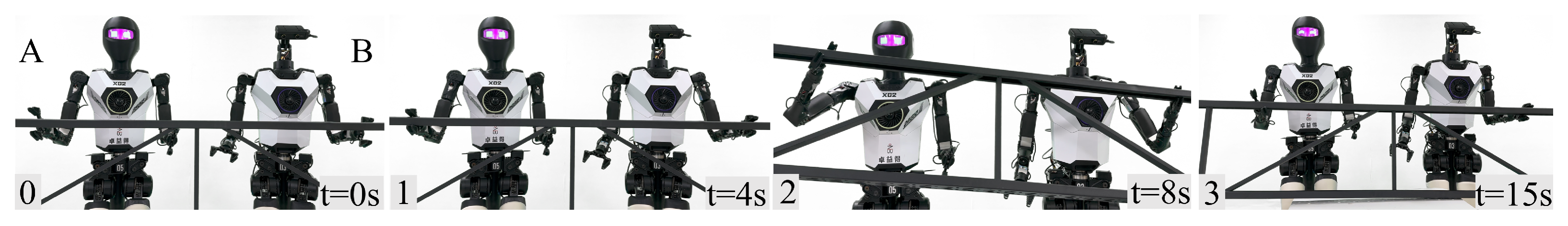
For the large object transport task, as shown in
Figure 12, the table contains a metal frame (length—180 cm, width—40 cm, weighing—3.1 kg). Two robots collaborate to transport this frame. Due to the size and weight of the target object, a single robot would face challenges such as instability in maintaining the center of gravity and insufficient torque in the arm motors. By working together, the two robots can grasp and lift the object cooperatively, reducing the difficulty of the task.
It should be noted that while the appearance of the bipedal robots executing the tasks differs from those previously described, the structural dimensions of the robot arms are identical.
5. Conclusions
This paper presents a comprehensive real-time multi-humanoid robot arm motion imitation framework, which employs an improved retargeting method to successfully achieve an optimal balance between arm kinematic configuration and end-effector accuracy. By integrating multi-person pose estimation technology, the framework not only supports collaborative motion among multiple humanoid robots but also provides an effective solution for multi-robot cooperation in complex tasks.
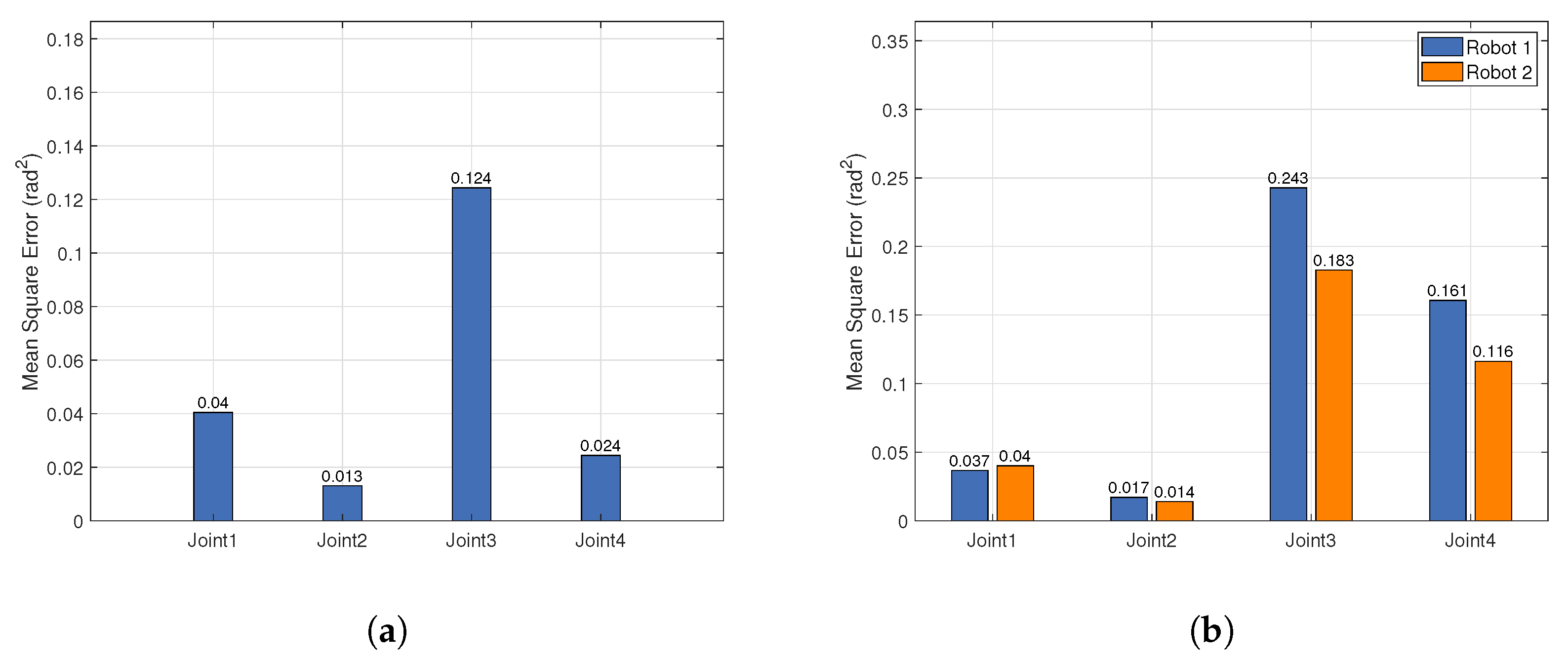
Experimental results demonstrate that the robots can successfully replicate various human arm movements. Although pose estimation errors increase with the number of demonstrators, the overall motion imitation still maintains high tracking accuracy and end-effector precision. Additionally, in tasks such as pouring water, item classification, and collaboration, we further verified the superior performance of the improved retargeting method in ensuring both arm kinematic structure integrity and end-effector accuracy. Furthermore, with the integration of multi-person pose estimation technology, the system maintains good real-time performance even as the number of detected objects increases, effectively avoiding significant computational load increases.
Although the framework performs excellently in terms of both high accuracy and efficiency, there are still certain limitations in pose tracking. Future research will focus on further optimizing pose estimation techniques to achieve comprehensive tracking of both position and posture, thereby enhancing the robot’s flexibility and precision in complex tasks and enabling it to play a greater role in multi-agent interactions and cooperative tasks.


 ,
, 


