Abstract
Aluminum alloy is crucial for lightweight and fuel-efficient vehicles due to its strength, lightness, and corrosion resistance. However, welding aluminum vehicle parts poses challenges, particularly porosity issues caused by trapped hydrogen gas in the weld metal. This study aimed to investigate the impact of the welding room environment on the health and properties of aluminum welding joints. To achieve this, an isolated room was created, where variations in airflow velocity (1.1 m/s, 1.6 m/s, and 2.1 m/s) and temperature (19 °C, 27 °C, and 35 °C) were implemented. The fume condition of the room was assessed to determine its impact on health aspects, while bead appearance and macrostructure were evaluated to assess weld joint quality. Results revealed that higher airflow velocity and temperature reduced fume concentration in the welding room, indicating a healthier environment. However, these conditions also led to increased porosity defects and influenced the performance of the shielding gas. Additionally, higher ambient temperatures increased hydrogen solubility in the molten aluminum, exacerbating porosity issues. For optimal welder comfort and high-quality weld joints, it is recommended to maintain a low temperature and airflow velocity in the welding room, ensuring a healthier working environment while minimizing porosity defects.
1. Introduction
Steel is increasingly being substituted by aluminum in the last few decades [1]. This is due to the fact that aluminum and its alloys are the most important materials to meet future automotive needs because of their numerous advantages such as light weight and corrosion resistance [2]. For example, aluminum is widely used to manufacture light rail transit (LRT) and high-speed trains (HST) because of its high strength, excellent machinability, and low price [3,4].
The automotive car body joining and production processes involve the application of different welding techniques to ensure effectiveness. Meanwhile, welding is defined as the process of joining materials through the application of heat to ensure they are melted with or without pressure and filler metals [5]. The widespread use of welding is due to its good metallurgical and superior mechanical properties as well as low cost [6]. However, welding joints of aluminum have certain weaknesses such as the porosity in the weld metal [7] due to the solubility of hydrogen, with further effects on the weld quality [8]. This is mainly because the hydrogen solubility in molten aluminum is higher than in the solid form. Therefore, the solubility usually increases as the temperature increases, especially when the aluminum melts during the welding process, thereby leading to the trapping of a lot of hydrogen gas in the weld metal [9,10,11].
The welding environment is one source of hydrogen, and it is important to the control of joint porosity. Its influence on porosity can be associated with wind speed, humidity, dissolved oxygen, and air temperature [1], and this means controlled environmental conditions can produce good welding [12]. Moreover, there is also the need to consider the health aspects in addition to the environment due to the ability of welding fumes to cause problems and potential health risks for the welder [13]. It is important to note that welding fumes are a complex mixture of solid metal particles and gases [14]. These particles are so small that they can be inhaled by the welders, with consequences on their respiratory system. The formation of these fumes depends on amperage, voltage, gas, arc temperature, duration, electrode, material, and heat input in the welding process [15,16]. Those produced in aluminum welding have been reported to be more dangerous for the welder’s health than steel because the process associated with aluminum welding contains NOx, Zn, CrO, Ni, Cu, Mn, and high exposure to Al [17]. These contents can cause several diseases such as Parkinson’s [18,19], fatigue, muscle aches, headaches, bronchial hyperactivity, pleuritic chest pain, aspergillus pneumonia, hemoptysis, and pneumoconiosis [20]. Meanwhile, the welding fume can be controlled by increasing the ventilation and ensuring the circulation of air in the welding room to reduce the quantity to be inhaled by the welder.
The previous studies on aluminum welding joints have only focused on evaluating the basic mechanical and physical properties without examining the environmental factors. Information on the environmental effects is limited. Therefore, this study was conducted to determine the effect of airflow velocity and temperature on the physical characteristics of the AA5083 welding joints as well as the air quality of the welding room. The findings are expected to be utilized in designing a healthy welding environment to produce high-quality welding joints of aluminum.
2. Materials and Methods
Aluminum alloy AA5083 with a size of 300 mm × 300 mm × 6 mm was welded using ER5356 filler wire (SOWESCO—Pinnacle Alloys, Houston, TX, USA) with a diameter of 1.0 mm. The chemical compositions of both are indicated in Table 1. Moreover, the welding process was conducted in an isolation room equipped with an air conditioner and blower, presented in Figure 1, to ensure proper control of the environmental parameters. The air conditioner was used to control the temperature, while the blower was applied to set the airflow velocity. The welding specimen was a single V butt joint welding joint. It is important to note that a V groove at an angle of 60° and a gap of 1 mm were used such that the gap was applied to increase the welding penetration as illustrated in Figure 2, while the forehand method of welding was also used as illustrated in Figure 3. The welding was performed by a certified welder using Gas Metal Arc Welding MERKLE COMPACT MIG PRO 210 K (Merkle Schweissanlagen, Kötz, Germany) with 99% argon shielding gas, 24.5 Volt, 150–170 ampere. It is pertinent to state that the environmental parameters used included the airflow velocity, which was varied at 1.1, 1.6, and 2.1 m/s, as well as the air temperature at 19 °C, 27 °C, and 35 °C, as listed in Table 2.

Table 1.
The chemical composition of AA5083 and AA5356 (wt%).
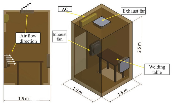
Figure 1.
Welding isolation room.
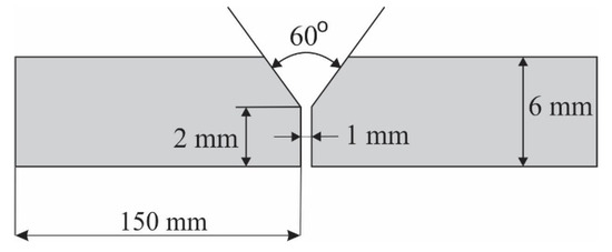
Figure 2.
Geometry of the welding specimen.
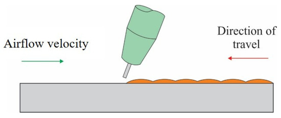
Figure 3.
Forehand welding technique.

Table 2.
Research parameters.
The experiment was conducted to determine the amount and particle size of the welding fume as well as the air quality of the welding room. The particle size was measured using the KRISBOW 10,207,854 (PT. Kawan Lama, Jakarta, Indonesia) presented in Figure 4 for 6 min during the welding process. Meanwhile, the air quality measurement tool was placed in the welding isolation room and on a portable near the welder as shown in Figure 5. The particles were collected during welding using 8 pieces of clear glass measuring 10 mm × 10 mm placed at the closest distance to the welding groove, as illustrated in Figure 6. The particles of the welding fumes collected were transferred to a container for further analysis using SEM-EDX ZEISS EVO MA 10 (Carl Zeiss, Oberkochen, Germany) for detailed characterization based on the quantity, size, shape, and chemical content. Moreover, the welding fume was captured visually from the front position using a digital camera to determine its direction after several environmental parameters had been set.
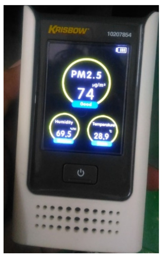
Figure 4.
Air quality measuring device.
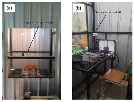
Figure 5.
Position of the air quality device: (a) side view and (b) front view.
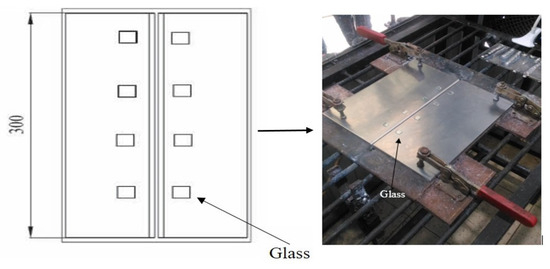
Figure 6.
Collector glass for the welding fume particles.
Bead appearance and macrostructural observations were made using an OLYMPUS SZ2 ILST stereo zoom microscope (Labexchange, Burladingen, Germany) with a magnification of 1.5X to identify welding defects. The standard procedures to analyze the macrostructure include cutting, framing, polishing with sandpaper, and etching. It is important to note that the etching solution composition consisted of 2 mL HF, 3 mL HCL, 5 mL HNO₃, and 190 mL water according to the ASTM E407-07 test standard. The observed areas were the base metal, HAZ (heat-affected zone), and weld metal.
3. Results and Discussion
3.1. Distribution of Welding Fume Particles
Welding fumes consist of small particles generated during the welding process as a result of combustion. These particles can pose a risk to human health when inhaled excessively. Typically, they are formed when solid materials vaporize at high temperatures. Recent studies have highlighted the significant contribution of electrode vaporization to the production of welding fumes [21]. Research findings have demonstrated that the airflow velocity and temperature play crucial roles in determining the concentration of welding fumes in a welding room (refer to Figure 7, Figure 8, Figure 9 and Figure 10). Figure 7 indicates that an airflow velocity of 1.1 m/s and a temperature of 19 °C resulted in the highest recorded fume content, whereas the lowest concentration was observed at 2.1 m/s and 35 °C (Figure 9). This observation can be attributed to the fact that high airflow velocity facilitates the efficient removal of fumes from the welding room, ensuring a smooth circulation of air. Dajian et al. [22] also reported that high airflow velocity contributes to reducing fume concentration within a welding room. Maintaining arc stability has been identified as another crucial factor in minimizing welding fume production. This aligns with the findings of Vishnu et al. [23], who observed that improved welding arc stability resulted in lower welding fume levels. However, it is important to note that excessively high airflow velocity can have adverse effects. Such conditions can lead to erratic movement of fumes, creating a vortex of fumes that accumulates within the welding room. Therefore, striking a balance between adequate airflow velocity and stability is crucial for managing welding fume exposure effectively.
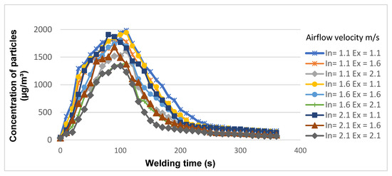
Figure 7.
Welding fume particles in the welding room at 19 °C.
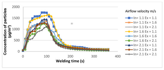
Figure 8.
Welding fume particles in the welding room at 27 °C.
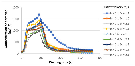
Figure 9.
Welding fume particles in the welding room at 35 °C.
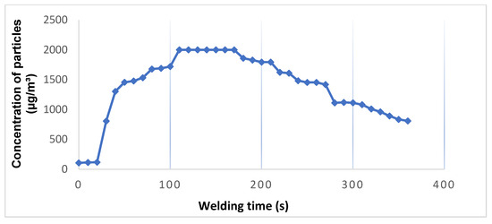
Figure 10.
Welding fume particles in the welding room without air circulation.
The findings presented in Figure 10 indicate that the number of welding fume particles in the welding room without airflow and at room temperature is higher compared to in the conditions with airflow. This can be attributed to the lack of airflow to push the fumes out of the room, resulting in their accumulation. The accumulation of welding fume particles in the absence of air circulation is a cause for concern due to the potential risks they pose to welders. A previous report [24] has already established that a large amount of welding fume can create a dangerous environment for welders. When the fumes are not effectively removed from the air, they remain suspended for longer periods, increasing the likelihood of inhalation by the welder. Inhalation of welding fume particles can lead to various health issues and respiratory problems [17]. The particles may contain hazardous substances such as metal oxides, volatile organic compounds, and other toxic components, depending on the materials being welded. Prolonged exposure to these particles can result in short-term effects like irritation of the respiratory system, coughing, and wheezing. Additionally, long-term exposure may lead to more serious conditions such as chronic lung diseases, including occupational asthma, bronchitis, and even lung cancer [17]. To ensure a safe working environment for welders, proper ventilation and air circulation are crucial. Adequate airflow helps to remove welding fumes from the work area, minimizing the concentration of harmful particles in the air. This can be achieved through the use of ventilation systems, such as local exhaust ventilation (LEV), which captures the fumes at the source and directs them away from the welder’s breathing zone.
The temperature within the welding room was found to have an impact on the presence of welding fume particles, as indicated by the results showing a lower number of particles at 35 °C compared to 19 °C. This observation suggests that higher temperatures can slow down the growth rate of welding fumes and reduce the density of the particles [25]. This finding aligns with the research conducted by Vishnyakov et al. [26], which demonstrated a significant decrease in the total generation rate of welding fumes with increasing temperature. While higher temperatures may contribute to better air quality by reducing the production of fumes, it is not recommended to weld at excessively high temperatures. The primary concern during welding operations is not only to ensure good air quality but also to maintain the welder’s comfort and safety. The recommended temperature range for welding falls between 23 °C and 26 °C, as indicated in Table 3 [27]. This range provides a comfortable working environment for the welder, even though it may not be optimal for achieving the best air quality. It is crucial to consider the welding environment holistically in order to ensure both the comfort of the welder and the production of high-quality welding joints. While higher temperatures may help improve air quality, they should be regulated within the recommended range to prioritize the well-being and safety of the welder. Other factors such as proper ventilation, appropriate personal protective equipment, and adherence to established safety guidelines should also be considered to create a comfortable and safe working environment. By taking these factors into account, it is possible to strike a balance between maintaining comfortable working conditions for the welder and ensuring good air quality. This approach contributes to the overall goal of promoting the health and safety of welders while producing welds of high quality.

Table 3.
Recommended air quality parameter standard values.
The welding fumes in the study were identified through visual observation of glass samples placed around the aluminum being welded using a scanning electron microscope (SEM). The results revealed that the shape and size of the welding fume particles were consistent across all the samples tested. This included specimens welded in both the no-airflow-velocity, no-temperature-control welding room and the room with an inhaust–exhaust of 2.1 m/s airflow velocity and a temperature of 35 °C. The shape and chemical composition of the two samples are presented in Figure 11 and Figure 12, respectively. The analysis indicated that the welding fume particles had an average size in the micron range and accumulated in various shapes, sizes, and quantities. The average size of the particles was approximately <2 µm, making them easily inhalable by humans. This poses a potential health risk due to the chemical content of the fumes, which can lead to various diseases. Furthermore, the energy-dispersive X-ray (EDX) test results, shown in Figure 11b and Figure 12b, provided insights into the chemical composition of the welding fumes. In the no-airflow room, the dominant elements were aluminum (Al) and oxygen (O). These elements can combine to form aluminum oxide (Al2O3), indicating the presence of both aluminum oxide (Al2O3) and pure aluminum in the sample. Pure aluminum was predicted to be located in the central region and have a larger size, while aluminum oxide (Al2O3) was found in the outer layer with a smaller size. On the other hand, in the room with airflow, the dominant elements in the welding fumes were carbon (C) and oxygen (O). These elements can bond to produce carbon monoxide (CO). Additionally, aluminum (Al) and magnesium (Mg) were also present, forming the compound aluminum magnesium (AlMg). Trace elements of silicon (Si), chromium (Cr), chloride (Ca), and titanium (Ti) were also detected in both samples. These elements were formed from the residue obtained during the burning of the base metal and filler materials. It is worth noting that the chemical composition of the welding fume particles depends on the composition of the filler wire, which does not undergo significant changes with the metal transfer mode [28]. This implies that the chemical composition of the welding fumes can be influenced by the specific materials used in the welding process. The comprehensive analysis of the shape and chemical composition of the welding fumes provides valuable insights into their characteristics and potential health implications. By understanding the nature of these particles, appropriate measures can be implemented to mitigate their risks and protect the health and safety of welders.
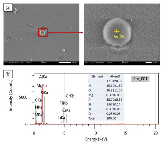
Figure 11.
The shape of the welding fume in no-airflow room (a) and the chemical composition of the fume particles (b).
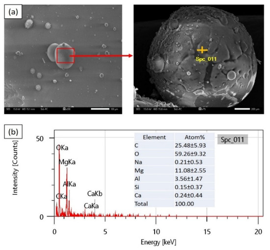
Figure 12.
The shape of the welding fume in room with the airflow velocity inhaust–exhaust of 2.1 m/s and at a temperature of 35 °C (a) and the chemical composition of the welding fume particles (b).
3.2. Welding Fume Flow Direction
The presence of an inhaust and exhaust fan in the welding room offers several benefits for the welder, particularly in terms of fume extraction. The effectiveness of the airflow in removing welding fumes from the room was captured using a digital camera. The high airflow velocity facilitated the immediate extraction of fumes from the welding area. This finding aligns with the observation made by Dajian [22], who stated that fume levels tend to decrease in the welding room as airflow velocity increases. Furthermore, another study highlighted the significant influence of airflow velocity and temperature on the concentration of welding fumes in a room [29]. Adequate ventilation and proper airflow are essential for maintaining a healthy welding environment. When the welding fumes can escape through the provided ventilation system, the number of particles in the room decreases significantly. By implementing an effective inhaust and exhaust fan system, the concentration of welding fumes in the room can be reduced, providing a healthier and safer working environment for the welder. The extraction of fumes through proper ventilation helps to minimize the welder’s exposure to hazardous particles, mitigating potential health risks associated with inhalation. It is crucial to ensure that the ventilation system is appropriately designed and maintained to achieve optimal fume extraction. This includes positioning the exhaust fan near the welding source to capture the fumes directly at the point of generation. Additionally, regular inspection and cleaning of the ventilation system are necessary to prevent clogging and maintain its efficiency.
3.3. Physical Characteristics of Weld Joint
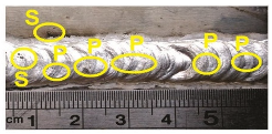
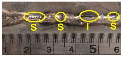
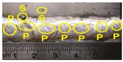
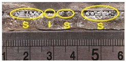
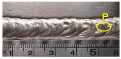
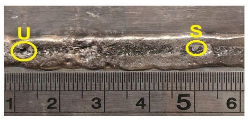
The visual observations conducted on the welding joints revealed a wide variety of bead shapes, making them difficult to differentiate. Furthermore, the impact of temperature and airflow velocity on the welds was visually identified, as shown in Table 4. It was observed that the bead width of the joint welded at 19 °C with an inhaust–exhaust of 1.1 m/s airflow velocity appeared to be smaller compared to that of those welded at 35 °C with 2.1 m/s. The findings indicated that the application of a lower temperature in the welding room resulted in a smaller welding bead and a faster cooling rate. This observation aligns with a previous study that suggested a lower ambient temperature generally leads to a narrower welding bead width [30]. The cooling rate during the welding process is influenced by various factors, including ambient temperature, heat input, and the thermal conductivity of the materials being welded. A smaller welding bead width caused by low temperature can have implications for the overall weld quality and strength. It may indicate a rapid solidification and reduced fusion between the base metals, potentially leading to weaker joints. It is important to ensure adequate fusion and proper penetration during the welding process to achieve strong and reliable welds. Controlling the temperature and ensuring appropriate heat input are critical factors in achieving desired weld characteristics. The specific welding parameters, such as temperature, current, and travel speed, should be carefully selected and optimized based on the materials, joint design, and intended application. This helps to achieve the desired bead size, penetration, and fusion while maintaining the integrity of the welded joint. Bead shape and width are not the only factors determining the quality of a weld. Other parameters, such as penetration depth, bead reinforcement, and the absence of defects like porosity and cracks, also contribute to the overall weld quality. Visual observations of the welds provide valuable insights into the appearance of the weld, allowing for the identification of potential issues and the implementation of necessary adjustments.

Table 4.
Welding bead appearance due to environment parameters (spatter (S), incomplete penetration (I), and porosity (P)).
The welding defects identified on a weld involving AA5083 aluminum are indicated in Figure 13. The welding defects identified on a weld involving AA5083 aluminum are indicated in Figure 13, and those found through visual observations included spatter (S), incomplete penetration (I), and porosity (P). The porosity was observed to be numerous and often appeared on the welding surface with the highest number recorded at the inhaust–exhaust of 2.1 m/s airflow velocity with a temperature of 35 °C, while the least was at 1.1 m/s and 19 °C. It means an increase in room temperature can increase the level of porosity. It is pertinent to note that the high quantity of porosity is due to the increment in the hydrogen content which was caused by the high temperatures in the welding environment. Zhao et al. [31] stated that hydrogen can dissolve readily in a weld pool at high temperatures. It is also important to state that the airflow velocity can disrupt the shielding gas and reduce its protection ability. This makes the hydrogen gas dissolve quickly, settle, and become trapped in the weld metal, thereby leading to porosity [8].
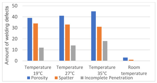
Figure 13.
Number of defects on the welding bead.
The presence of spatter defects was observed in all the specimens, with varying numbers depending on the welding conditions. Visual observations revealed that the highest amount of spatter was recorded at 19 °C, while the lowest amount was found at 35 °C. The large amount of spatter produced at low-ambient-temperature conditions can be attributed to the high cooling rate. Rapid cooling leads to the rapid solidification of spatter on the base metal, making it more difficult to remove. This observation aligns with the findings of Wagner et al. [32], who reported that spatter solidifies quickly on the base metal when subjected to rapid cooling. Furthermore, the airflow velocity in the welding environment plays a role in the behavior of welding droplets. The airflow velocity causes the welding droplets to be carried in the direction of the airflow velocity, which is opposite to the direction of the welding process. This disrupts the stability of the welding arc and can contribute to increased spatter production. The welding speed also influences the occurrence of spatter defects. An increase in welding speed is generally associated with a reduction in spatter. This finding is consistent with previous studies [33], which have shown that higher welding speeds can help minimize spatter formation. Spatter defects are undesirable in welding as they can affect the appearance, integrity, and quality of the weld. Spatter can lead to porosity, reduced fusion, and weaker joints if not properly addressed. Therefore, measures should be taken to minimize spatter during the welding process.
The depth of welding penetration can be enhanced by utilizing appropriate shielding gas parameters [34]. It is important to ensure that the shielding gas is properly maintained during the welding process as a disturbed or disrupted shielding gas can result in reduced penetration depth and the formation of cavities at the base of the weld metal. Incomplete penetration defects were primarily observed in specimens welded at 35 °C with an inhaust airflow velocity of 2.1 m/s. The high airflow velocity in this condition allows air to enter the bottom of the weld, interfering with the welding process. As a consequence, the molten filler wire is unable to adequately fill the weld cavity, resulting in incomplete penetration. The unstable arc caused by the high airflow velocity further exacerbates the issue by reducing the filling of the weld metal at the bottom of the welding path [35]. Incomplete penetration defects can negatively impact the quality and strength of the weld joint. Insufficient fusion between the base metals and the filler material can lead to weakened welds, compromising their structural integrity. It is essential to ensure complete penetration to achieve robust and reliable welds. To mitigate incomplete penetration defects, it is crucial to maintain a stable shielding gas environment. This involves ensuring proper gas flow, adequate shielding gas coverage, and appropriate nozzle design. Additionally, optimizing welding parameters such as arc length, travel speed, and current can contribute to achieving satisfactory penetration depth.
The macrostructure of the welding joints was examined, revealing the presence of more porosity defects in specimens welded at 35 °C with an inhaust airflow velocity of 2.1 m/s compared to in those welded at 19 °C with an inhaust airflow velocity of 1.1 m/s, as illustrated in Figure 14. This disparity can be attributed to the direct contact between the airflow velocity and the welding arc. The high temperature and increasing airflow velocity at 35 °C and 2.1 m/s, respectively, facilitate the faster diffusion of hydrogen into the weld pool. The hydrogen atoms then precipitate on the weld metal, leading to the formation of porosity [36]. During the welding process, hydrogen bubbles enter the weld pool due to the high temperatures. Hydrogen atoms have the ability to dissolve easily in the liquid weld pool at elevated temperatures [37]. The presence of hydrogen in the weld pool can cause porosity defects to form as the hydrogen atoms accumulate and coalesce, creating gas pockets within the solidified weld metal. Porosity defects in welds can compromise the structural integrity and mechanical properties of the joint. These voids act as stress concentrators and may lead to reduced load-bearing capacity, increased susceptibility to cracking, and reduced corrosion resistance. Therefore, minimizing porosity is crucial to ensure the quality and reliability of the weld. To mitigate porosity defects, it is important to address the sources of hydrogen in the welding process. This involves implementing proper cleaning and preparation techniques to remove contaminants from the base metal and filler material. Additionally, controlling the welding environment, including the shielding gas composition and flow rate, can help minimize the introduction of hydrogen during the welding process.
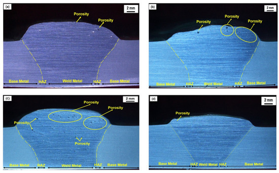
Figure 14.
The macrostructure of the welding joints in room with (a) inhaust 1.1 m/s, exhaust 1.1 m/s, and 19 °C, (b) inhaust 1.6 m/s, exhaust 1.6 m/s, and 27 °C, and (c) inhaust 2.1 m/s, exhaust 2.1 m/s, and 35 °C, as well as (d) without airflow.
4. Conclusions
This study analyzed the effect of airflow velocity and temperature on the physical properties of AA5083 welding joints and the air quality in the welding room, and the conclusions drawn are as follows:
- Airflow velocity and ambient temperature affect the fume content in the welding room. This is indicated by the fact that a higher airflow velocity was observed to lead to the removal of more welding fume from the welding room. Meanwhile, an increase in the temperature slowed down the growth rate and reduced the density of welding fume particles;
- Increased airflow velocity and temperature during welding caused porosity defects and incomplete penetration. It was also discovered that welding at low temperatures led to spatter defects.
Author Contributions
Conceptualization, N.M. and T.T.; methodology, R.D.A.; software, E.P.B.; validation, A.M.K.; investigation, R.D.A.; writing—original draft preparation, R.D.A.; writing—review and editing, T.T.; visualization, E.P.B.; supervision, A.M.K.; funding acquisition, T.T. All authors have read and agreed to the published version of the manuscript.
Funding
This research was funded by through Matching Fund 2023 grant with contract 265/E1/HK.02.02/2023 and 9055/UN1.P/DPU/HK.08.00/2023, and Mandatory Universitas Sebelas Maret 2023 grant with contract 228/UN27.22/PT.01.03/2023.
Institutional Review Board Statement
Not applicable.
Informed Consent Statement
Not applicable.
Data Availability Statement
The data presented in this study are available on request from the corresponding author.
Acknowledgments
Authors would like to thank the University of Sebelas Maret Surakarta, Indonesia, a lot for providing many facilities, Arif for preparing equipment set-ups, the BARISTA program, and all students in the METALS research group for assisting with this research.
Conflicts of Interest
The authors declare no conflict of interest. The funder had no role in the design of the study; in the collection, analyses, or interpretation of data; in the writing of the manuscript; or in the decision to publish the results.
References
- Ardika, R.D.; Triyono, T.; Muhayat, N. A review porosity in aluminium welding. Procedia Struct. Integr. 2021, 33, 171–180. [Google Scholar] [CrossRef]
- Chinakhov, D.A.; Vorobyev, A.V.; Grigorieva, E.G.; Mayorova, E.I. Study of Wind Velocity Impact upon the Quality of Shielding and upon the Thermal Processes under MAG Welding. Appl. Mech. Mater. 2015, 770, 253–257. [Google Scholar] [CrossRef]
- Ni, W.; Yang, S.; Jia, J.; Bai, J.; Lin, Y. Fatigue property of Al-5Zn-2Mg aluminium alloy welding joints used in high-speed trains. Xiyou Jinshu Cailiao Yu Gongcheng/Rare Met. Mater. Eng. 2016, 45, 2774–2778. [Google Scholar] [CrossRef]
- Liu, Y.; Wang, W.; Xie, J.; Sun, S.; Wang, L.; Qian, Y.; Meng, Y.; Wei, Y. Microstructure and mechanical properties of aluminium 5083 weldments by gas tungsten arc and gas metal arc welding. Mater. Sci. Eng. A 2012, 549, 7–13. [Google Scholar] [CrossRef]
- Jeffus, L. Welding: Principles and Applications, 9th ed.; Cengage Learning: Singapore, 2020; pp. 3–4. [Google Scholar]
- Dhanashekar, M.; Loganathan, P.; Ayyanar, S.; Mohan, S.R.; Sathish, T. Mechanical and wear behaviour of AA6061/SiC composites fabricated by powder metallurgy method. Mater. Today Proc. 2020, 21, 1008–1012. [Google Scholar] [CrossRef]
- Cueca, F.; Patarroyo, A.; Rojas, F.; Solano, E.; Morales, A.; Muñoz, R. Study of the weld ability of Aluminium Alloy 5083 H116 with Pulsed Arc GMAW (GMAW-P). Ship Sci. Technol. 2012, 6, 43–56. [Google Scholar] [CrossRef][Green Version]
- Yu, H.; Xu, Y.; Song, J.; Pu, J.; Zhao, X.; Yao, G. On-line monitor of hydrogen porosity based on arc spectral information in Al–Mg alloy pulsed gas tungsten arc welding. Opt. Laser Technol. 2015, 70, 30–38. [Google Scholar] [CrossRef]
- Han, Y.; Xue, S.; Fu, R.; Lin, L.; Lin, Z.; Pei, Y.; Sun, H. Influence of hydrogen embrittlement on impact property and microstructural characteristics in aluminium alloy weld. Vacuum 2020, 172, 109073. [Google Scholar] [CrossRef]
- Han, Y.; Xue, S.; Fu, R.; Zhang, P. Effect of hydrogen content in ER5183 welding wire on the tensile strength and fracture morphology of Al–Mg MIG weld. Vacuum 2019, 166, 218–225. [Google Scholar] [CrossRef]
- Huang, Y.; Yuan, Y.; Yang, L.; Wu, D.; Chen, S. Real-time monitoring and control of porosity defects during arc welding of aluminium alloys. J. Mater. Process. Technol. 2020, 286, 116832. [Google Scholar] [CrossRef]
- Gou, G.; Zhang, M.; Chen, H.; Chen, J.; Li, P.; Yang, Y.P. Effect of humidity on porosity, microstructure, and fatigue strength of A7N01S-T5 aluminium alloy welded joints in high-speed trains. Mater. Des. 2015, 85, 309–317. [Google Scholar] [CrossRef]
- Chang, Y.; Sproesser, G.; Neugebauer, S.; Wolf, K.; Scheumann, R.; Pittner, A.; Rethmeier, M.; Finkbeiner, M. Environmental and Social Life Cycle Assessment of welding technologies. Procedia CIRP 2015, 26, 293–298. [Google Scholar] [CrossRef]
- Rana, H.K.; Akhtar, M.R.; Ahmed, M.B.; Liò, P.; Quinn, J.M.W.; Huq, F.; Moni, M.A. Genetic effects of welding fumes on the progression of neurodegenerative diseases. NeuroToxicology 2019, 71, 93–101. [Google Scholar] [CrossRef] [PubMed]
- Safe Work Australia. Guidance on the Interpretation of Workplace Exposure Standards for Airborne Contaminants. Available online: http://www.safeworkaustralia.gov.au/sites/SWA/about/Publications/Documents/680/Guidance_Interpretation_Workplace_Exposure_Standards_Airborne_Contaminants.pdf (accessed on 6 June 2022).
- Schoonover, T.; Conroy, L.; Lacey, S.; Plavka, J. Personal exposure to metal fume, NO2, and O3 among production welders and non-welders. Ind. Health 2011, 49, 63–72. [Google Scholar] [CrossRef] [PubMed]
- Golbabaei, F.; Khadem, M. Air Pollution in Welding Processes—Assessment and Control Methods. Current Air Quality Issues; InTech: London, UK, 2015. [Google Scholar] [CrossRef]
- Racette, B.A.; Criswell, S.R.; Lundin, J.I.; Hobson, A.; Seixas, N.; Kotzbauer, P.T.; Evanoff, B.A.; Perlmutter, J.S.; Zhang, J.; Sheppard, L.; et al. Increased risk of parkinsonism associated with welding exposure. NeuroToxicology 2012, 33, 1356–1361. [Google Scholar] [CrossRef] [PubMed]
- Sakib, N.; Chowdhury, U.N.; Islam, M.B.; Quinn, J.M.; Moni, M.A. A systems biology approach to identifying genetic factors affected by aging, lifestyle factors, and type 2 diabetes that influences Parkinson’s disease progression. Inform. Med. Unlocked 2020, 21, 100448. [Google Scholar] [CrossRef]
- Hull, M.J.; Abraham, J.L. Aluminium welding fume-induced pneumoconiosis. Hum. Pathol. 2002, 33, 819–825. [Google Scholar] [CrossRef]
- Vishnyakov, V.I.; Kiro, S.A.; Ennan, A.A. Formation of primary particles in welding fume. J. Aerosol Sci. 2013, 58, 9–16. [Google Scholar] [CrossRef]
- Dajian, L. Research on Diffusion and Control Technology of Welding Fume. J. Energy Nat. Resour. 2017, 6, 1. [Google Scholar] [CrossRef][Green Version]
- Vishnu, B.R.; Sivapirakasam, S.P.; Satpathy, K.K.; Albert, S.K.; Chakraborty, G. Influence of nano-sized flux materials in the reduction of the Cr (VI) in the stainless steel welding fumes. J. Manuf. Process. 2018, 34, 713–720. [Google Scholar] [CrossRef]
- Hong, T.S.; Ghobakhloo, M. Safety and Security Conditions in Welding Processes. Compr. Mater. Process. 2014, 6, 213–225. [Google Scholar] [CrossRef]
- Vishnyakov, V.I.; Kiro, S.A.; Oprya, M.V.; Ennan, A.A. Effects of shielding gas temperature and flow rate on the welding fume particle size distribution. J. Aerosol Sci. 2017, 114, 55–61. [Google Scholar] [CrossRef]
- Vishnyakov, V.I.; Kiro, S.A.; Oprya, M.V.; Ennan, A.A. Effect of shielding gas temperature on the welding fume particle formation: Theoretical model. J. Aerosol Sci. 2018, 124, 112–121. [Google Scholar] [CrossRef]
- Azmarini, A.N.; Majid, S.A.; Zakaria, S.H.; Sulaiman, S.A. A study on IAQ in a welding laboratory. Appl. Mech. Mater. 2013, 393, 947–952. [Google Scholar] [CrossRef]
- De Meneses, V.A.; Gomes, J.F.P.; Scotti, A. The effect of metal transfer stability (spattering) on fume generation, morphology and composition in short-circuit MAG welding. J. Mater. Process. Technol. 2014, 214, 1388–1397. [Google Scholar] [CrossRef]
- Duan, M.; Wang, Y.; Gao, D.; Yang, Y.; Cao, Z. Modeling dispersion mode of high-temperature particles transiently produced from industrial processes. Build. Environ. 2017, 126, 457–470. [Google Scholar] [CrossRef]
- Keanini, R.G.; Rubinsky, B. Three-dimensional simulation of the plasma arc welding process. Int. J. Heat Mass Transf. 1993, 36, 3283–3298. [Google Scholar] [CrossRef]
- Zhao, Y.; Zhou, X.; Liu, T.; Kang, Y.; Zhan, X. Investigate on the porosity morphology and formation mechanism in laser-MIG hybrid welded joint for 5A06 aluminium alloy with Y-shaped groove. J. Manuf. Process. 2020, 57, 847–856. [Google Scholar] [CrossRef]
- Wagner, D.C.; Yang, Y.K.; Kou, S. Spatter and porosity in gas-metal arc welding of magnesium alloys: Mechanisms and elimination. Weld. J. 2013, 92, 347s–362s. [Google Scholar]
- Wu, D.; Hua, X.; Huang, L.; Zhao, J. Numerical simulation of spatter formation during fiber laser welding of 5083 aluminium alloy at full penetration condition. Opt. Laser Technol. 2018, 100, 157–164. [Google Scholar] [CrossRef]
- Ming, G.; Xiaoyan, Z.; Qianwu, H. Effects of gas shielding parameters on weld penetration of CO2 laser-TIG hybrid welding. J. Mater. Process. Technol. 2007, 184, 177–183. [Google Scholar] [CrossRef]
- Chen, L.; Wang, C.; Xiong, L.; Zhang, X.; Mi, G. Microstructural, porosity and mechanical properties of lap joint laser welding for 5182 and 6061 dissimilar aluminium alloys under different place configurations. Mater. Des. 2020, 191, 108625. [Google Scholar] [CrossRef]
- Lu, K.; Lin, J.; Chen, Z.; Wang, W.; Yang, H. Safety assessment of incomplete penetration defects at the root of girth welds in pipelines. Ocean Eng. 2021, 230, 109003. [Google Scholar] [CrossRef]
- Toda, H.; Hidaka, T.; Kobayashi, M.; Uesugi, K.; Takeuchi, A.; Horikawa, K. Growth behavior of hydrogen micropores in aluminium alloys during high-temperature exposure. Acta Mater. 2009, 57, 2277–2290. [Google Scholar] [CrossRef]
Disclaimer/Publisher’s Note: The statements, opinions and data contained in all publications are solely those of the individual author(s) and contributor(s) and not of MDPI and/or the editor(s). MDPI and/or the editor(s) disclaim responsibility for any injury to people or property resulting from any ideas, methods, instructions or products referred to in the content. |
© 2023 by the authors. Licensee MDPI, Basel, Switzerland. This article is an open access article distributed under the terms and conditions of the Creative Commons Attribution (CC BY) license (https://creativecommons.org/licenses/by/4.0/).


