Article

Neutron Imaging at LANSCE—From Cold to Ultrafast

by
Ronald O. Nelson
1,*,
Sven C. Vogel
2,
James F. Hunter
3,
Erik B. Watkins
4,
Adrian S. Losko
2,
Anton S. Tremsin
5,
Nicholas P. Borges
2,6,
Theresa E. Cutler
7,
Lee T. Dickman
8,
Michelle A. Espy
3,
Donald Cort Gautier
3,
Amanda C. Madden
9,
Jaroslaw Majewski
10,11,
Michael W. Malone
12,
Douglas R. Mayo
13,
Kenneth J. McClellan
2,
David S. Montgomery
14,
Shea M. Mosby
1,
Andrew T. Nelson
15,
Kyle J. Ramos
16,
Richard C. Schirato
9,
Katlin Schroeder
17,
Sanna A. Sevanto
8,
Alicia L. Swift
18,
Long K. Vo
2,19,
Thomas E. Williamson
20 and
Nicola M. Winch
7
add Show full author list remove Hide full author list
1
LANSCEWeapons Physics (P-27), Los Alamos National Laboratory, Los Alamos, NM 87545, USA
2
Materials Science in Radiation Extremes (MST-8), Los Alamos National Laboratory, Los Alamos, NM 87545, USA
3
Applied Engineering Technology (AET-6), Los Alamos National Laboratory, Los Alamos, NM 87545, USA
4
Materials Synthesis and Integrated Devices (MPA-11), Los Alamos National Laboratory, Los Alamos, NM 87545, USA
5
Space Sciences Laboratory, University of California, Berkeley, Berkeley, CA 94720, USA
6
Department of Physics, Worcester Polytechnic Institute, Worcester, MA 01609, USA
7
Advanced Nuclear Technology (NEN-2), Los Alamos National Laboratory, Los Alamos, NM 87545, USA
8
Earth System Observations (EES-14), Los Alamos National Laboratory, Los Alamos, NM 87545, USA
9
Space Science and Applications (ISR-1), Los Alamos National Laboratory, Los Alamos, NM 87545, USA
10
Center for Integrated Nanotechnologies (MPA-CINT), Los Alamos National Laboratory, Los Alamos, NM 87545, USA
11
Molecular Biophysics Cluster BIO/MCB Molecular and Cellular Biosciences, National Science Foundation, Alexandria, VA 22314, USA
12
Applied Modern Physics (P-21), Los Alamos National Laboratory, Los Alamos, NM 87545, USA
13
Monte Carlo Codes (XCP-3), Los Alamos National Laboratory, Los Alamos, NM 87545, USA
14
Plasma Physics (P-24), Los Alamos National Laboratory, Los Alamos, NM 87545, USA
15
Engineered Materials (MST-7), Los Alamos National Laboratory, Los Alamos, NM 87545, USA
16
HE Science and Technology (M-7), Los Alamos National Laboratory, Los Alamos, NM 87545, USA
17
Department of Biology, University of New Mexico, Albuquerque, NM 87131, USA
18
Y-12 National Security Complex, P.O. Box 2009, Oak Ridge, TN 37831-8245, USA
19
Department of Nuclear Engineering, Kansas State University, Manhattan, KS 66506, USA
20
Paleontology, New Mexico Museum of Natural History and Science, Albuquerque, NM 87131, USA
*
Author to whom correspondence should be addressed.
J. Imaging 2018, 4(2), 45; https://doi.org/10.3390/jimaging4020045
Submission received: 5 December 2017 / Revised: 9 February 2018 / Accepted: 9 February 2018 / Published: 23 February 2018
(This article belongs to the Special Issue Neutron Imaging)

Abstract

:
In recent years, neutron radiography and tomography have been applied at different beam lines at Los Alamos Neutron Science Center (LANSCE), covering a very wide neutron energy range. The field of energy-resolved neutron imaging with epi-thermal neutrons, utilizing neutron absorption resonances for contrast as well as quantitative density measurements, was pioneered at the Target 1 (Lujan center), Flight Path 5 beam line and continues to be refined. Applications include: imaging of metallic and ceramic nuclear fuels, fission gas measurements, tomography of fossils and studies of dopants in scintillators. The technique provides the ability to characterize materials opaque to thermal neutrons and to utilize neutron resonance analysis codes to quantify isotopes to within 0.1 atom %. The latter also allows measuring fuel enrichment levels or the pressure of fission gas remotely. More recently, the cold neutron spectrum at the ASTERIX beam line, also located at Target 1, was used to demonstrate phase contrast imaging with pulsed neutrons. This extends the capabilities for imaging of thin and transparent materials at LANSCE. In contrast, high-energy neutron imaging at LANSCE, using unmoderated fast spallation neutrons from Target 4 [Weapons Neutron Research (WNR) facility] has been developed for applications in imaging of dense, thick objects. Using fast (ns), time-of-flight imaging, enables testing and developing imaging at specific, selected MeV neutron energies. The 4FP-60R beam line has been reconfigured with increased shielding and new, larger collimation dedicated to fast neutron imaging. The exploration of ways in which pulsed neutron beams and the time-of-flight method can provide additional benefits is continuing. We will describe the facilities and instruments, present application examples and recent results of all these efforts at LANSCE.

1. Introduction

More than 80 years after the first neutron image was produced [1,2] and 70 years after publication [1,3], advances in accelerator and, potentially, laser-driven neutron sources, as well as in detector technology and computing are creating imaging capabilities that are unique, powerful and complementary to X-ray and charged particle imaging. The availability of nuclear reactors in the 1960’s started the wider development of thermal neutron imaging. The status of the field in 1965 was described by Berger [4]. The 1980’s and 1990’s, with the advent of spallation neutron sources, were a time of testing for high-energy neutron imaging but spatial resolution and system efficiency were often not sufficient. Most of the techniques and equipment now being used quite effectively were under development 20 years ago [5]. In the early 2000’s very successful thermal neutron imaging programs were underway at PSI [6], FRM-2 [7], HZB [8] and NIST [9], with cold neutron advancements following [10]. More recently, neutron imaging is also available at J-PARC [11,12], ISIS [13] and other reactor and accelerator facilities with support from universities, government laboratories and companies.
The International Atomic Energy Agency (IAEA) maintains a list of reactor-based radiography facilities [14] and a recent publication by Lehmann [15] describes both spallation-neutron-source-based imaging facilities and reactor-based facilities. A detailed discussion and timeline for thermal neutron imaging development are provided in [2,16]. Of particular interest in this article is the development of time-of-flight (TOF) neutron imaging, also called energy-selective or energy-resolved neutron imaging. Early work on TOF neutron imaging at cold neutron energies was demonstrated in 1997 at LANSCE [17] and soon after in Japan [18]. While LANSCE was a neutron user facility since its inception in the 1980s [19], neutron imaging as described here became available only recently. The LANSCE User Program description and access is available on the web at http://lansce.lanl.gov/.
Non-destructive analysis techniques have been important at Los Alamos since the laboratory’s creation. Neutron radiography with thermal neutrons was performed for many years using the Omega West Reactor with routine use starting in 1976 [20,21]. The reactor was decommissioned in 1994 after almost 40 years of service. Numerous conventional and task specific X-ray and neutron radiography systems have been used over the years with X-rays spanning the range from a few keV sources to 20 MeV sources. In 1998, a portable neutron computed tomography (CT) capability was established using the recently developed commercial amorphous-Silicon (a-Si) flat panel technology [22]. The complementary technique of proton radiography was developed at the Los Alamos Neutron Science Center (LANSCE) in the mid 1990’s providing fast timing and magnetic lens magnification capabilities [23]. More recently muon imaging, invented at Los Alamos [24], using natural cosmic ray background radiation, is being used, for example, to aid in locating the nuclear fuel in the damaged Fukushima reactors [25,26], in assessing the integrity of ancient buildings [27] and locating voids in the Egyptian pyramids [28,29].
At LANSCE, high-energy (1–600 MeV) neutron radiography experiments were conducted in the mid 1990’s [30] and thermal and cold neutron imaging experiments followed [31]. The cold neutron measurements used a fast scintillator and CCD camera to perform energy-selective imaging exploiting Bragg-edge transmission [17]. However, only recently has interest in the imaging capabilities possible at LANSCE been rekindled, driven in large measure by advances in detectors, electronics and computers that make it possible to take full advantage of the beam properties at LANSCE.
LANSCE operates four neutron sources: (1) a moderated (water and liquid hydrogen) spallation neutron source—Target 1/Lujan Center, (2) a pulsed proton beam facility that may be configured as a neutron source for special pulsed modes (Target 2/Blue Room), (3) an unmoderated, high-energy spallation source (Target 4/WNR) and (4) a specially moderated source of ultra-cold neutrons (UCN) [32,33] (Target 3 was decommissioned and removed.). Targets 1 and 4 are utilized for neutron imaging, providing capabilities that span the energy range from cold neutrons to hundreds of MeV (ultrafast) and take advantage of the short-pulse characteristics of the LANSCE beams. The short (270 ns for Target 1 and < 1 ns for Target 4) proton beam pulses are uniquely well-suited for fast, time-gated imaging, both for nuclear resonances (eV to keV) to perform isotope- and element-specific imaging and at MeV energies to develop improved detectors and techniques for very-penetrating high-energy neutron imaging. Capabilities for specialized imaging, for example, phase contrast imaging using cold or thermal neutrons have been developed to provide contrast enhancement of edges, voids and other defects in materials that otherwise have contrast too poor for imaging. Objects studied range from phantoms inside thick uranium shielding to ancient fossils of large dinosaurs and of early mammals, from nuclear fuel pellets to doped scintillator materials and from small defects in materials to water uptake in roots and stems of plants. A wide range of state of the art imaging detector technologies has been used in these studies and new detectors are actively being developed.
Now at LANSCE, these advances are being used with the fast-pulsed and intense LANSCE neutron beams to perform previously unattainable measurements of element and isotope specific imaging by gating on specific nuclear resonances. High-energy neutron imaging has been developed to provide higher resolution and shorter imaging times than previously available. In addition, the high-energy neutron imaging detector developed at LANSCE has been employed with a state of the art laser-driven neutron source in a first demonstration of the potential for this new type of neutron source. This laser source creates possibilities for (1) very small source sizes (magnification and excellent resolution); (2) fast timing for flash neutron radiography and (3) reduced radiation backgrounds due to the directional nature of the source [34,35,36]. A neutron radiograph produced with high-energy neutrons from a single, laser-driven pulse from the TRIDENT laser at LANL is shown in Figure 1. This paper describes recent advances in neutron imaging with various neutron energies at LANSCE, provides application examples and presents some prospects for the future.

2. Materials and Methods

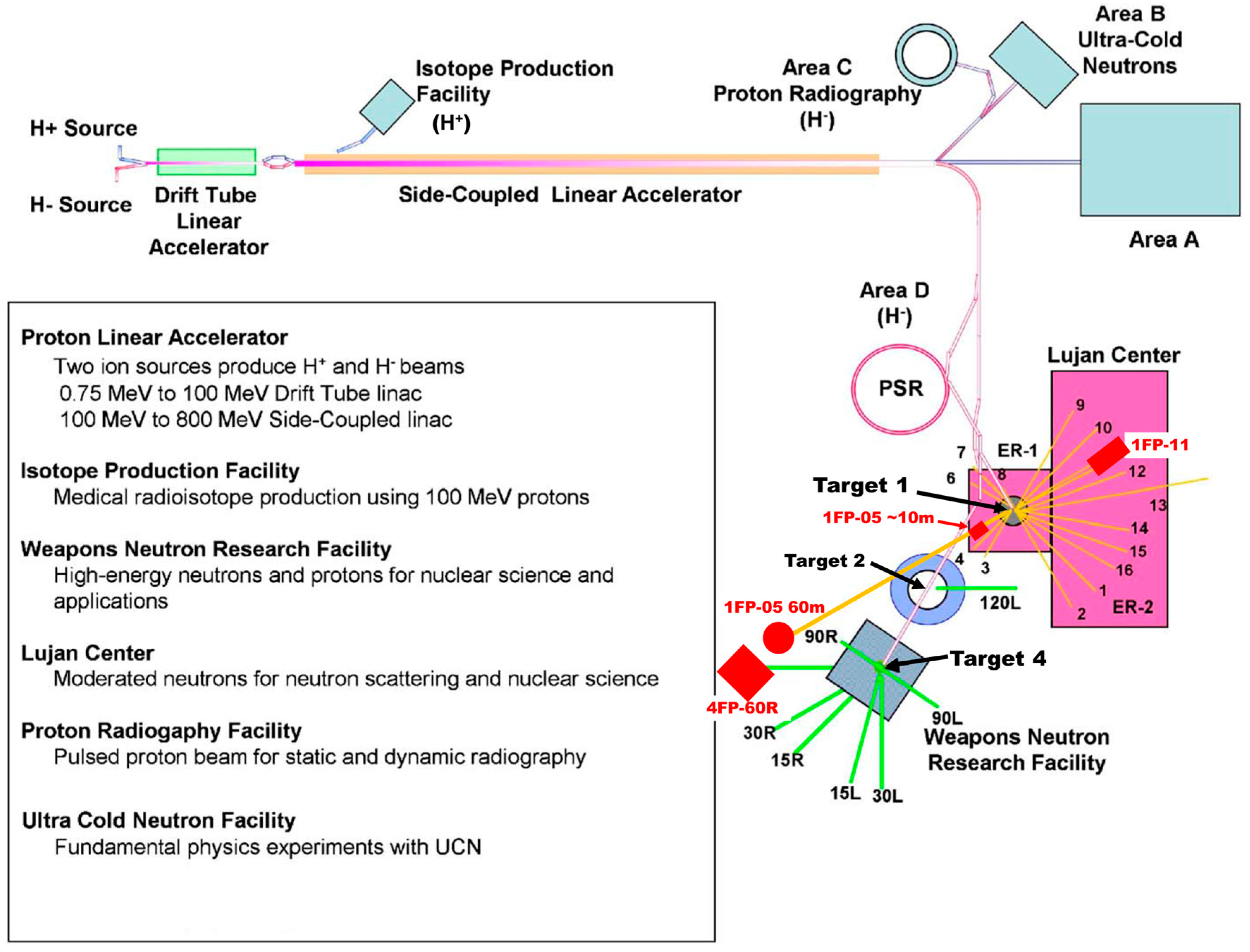
The LANSCE accelerator is an 800 MeV proton linear accelerator. A description of the facility and the neutron production targets is given by Lisowski and Schoenberg (2006) [32] and by Lisowski et al. (1990) [33]. A schematic overview of the facility is given in Figure 2. Two neutron production targets are routinely used. Target 1 is moderated by both water (thermal) and liquid hydrogen (cold) moderators with a total of 16 flight paths. Target 4 is an unmoderated neutron production target for high-energy (0.1 to 600 MeV) spallation neutron production, serving six beam lines. For Target 1, the spallation neutron pulses are created at 20 Hz by 270 ns long 800 MeV H+ pulses impinging on a tungsten target. For Target 4, the protons impinge on a tungsten target at 100 Hz with a typical macro-pulse length of 650 µs, broken down into sub-nanosecond wide micro-pulses separated by typically 1.8 µs. The neutron imaging work is currently carried out on three flight paths utilizing all of these energy ranges: (1) cold neutron imaging is performed on Target 1, Flight Path 11 (1FP-11) known as ASTERIX; (2) thermal neutron and resonance imaging is performed on Target 1, Flight Path 5 (1FP-05) and (3) high-energy neutron imaging uses the 60-degree right flight path of Target 4 (4FP-60R). Table 1 lists some typical parameters for these flight paths. A strength of the LANSCE neutron targets is the number of flight paths, the space available on the flight paths and that many of the flight paths can be configured to meet experiment needs. For example, there is considerable vertical space for imaging tall specimens.
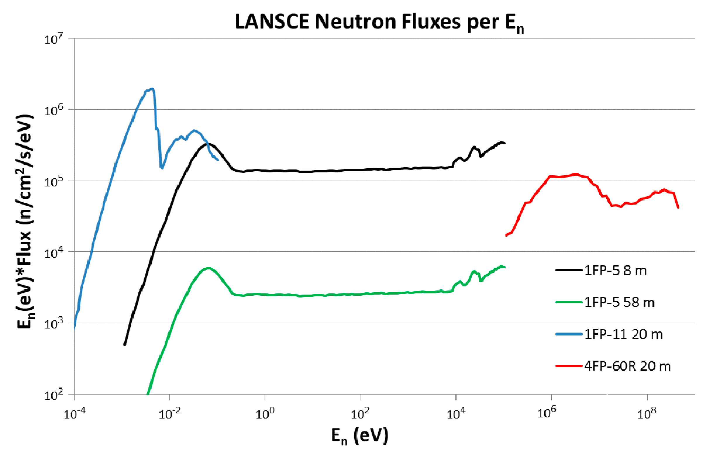
The LANSCE neutron fluxes versus incident energy are shown in Figure 3 plotted as neutron energy times flux. This is a useful way to represent the flux because it accounts for the increasing size of available energy bins with increasing neutron energy. The flux numbers plotted are the number of neutrons in a neutron energy bin of the same width as the center energy for that bin. For example, on the 4FP-60R beam line, at En = 10 MeV there are 6 × 10⁴ neutrons/cm2s in a 10 MeV wide energy bin from 5 to 15 MeV. The more often seen flux/eV (or /MeV) gives the mistaken impression that there are very few high-energy neutrons, when this is often far from the truth.
As shown in Table 2, the imaging detectors used in this work include, a Micro Channel Plate (MCP) low-energy neutron detector with Medi-Pix readout as described by Tremsin, et al. [38,39,40], a wide variety of CCD cameras including MCP fast-gating for TOF use, amorphous-silicon (a-Si) flat panel medical imaging detectors and storage phosphor image plates. These are described in more detail in the following sections.

3. Energy-Selective Neutron Imaging at 1FP-05

The combination of a pulsed, moderated neutron source with a pixelated neutron time-of-flight detector, recording several thousand neutron radiographs per neutron pulse, enables novel neutron imaging applications. Selection of radiographs at neutron energies (or time-of-flight) where a single isotope dominates the contrast (energy-selective neutron imaging) visualizes the distribution of that isotope. Similarly, neutron energies where a given feature is provided with the best possible contrast can be selected after the data collection. Fitting known cross-section data to the measured transmission data allows quantification of areal isotope densities, as well as non-destructive chemical analysis similar to X-ray fluorescence or mass-spectrometry but probing the bulk of a sample instead of its surface. The neutron energy resolution is determined by the time width of the proton beam (270 ns) that produces the neutrons and the flight path length (typically 8 m). To our knowledge, only LANSCE, J-PARC [41] and ISIS [42] have sufficient neutron energy resolution for eV to keV-region TOF imaging at present. This section describes the method and provides application examples.

3.1. Instrument Setup

The beam line utilized for energy-resolved neutron imaging is Flight-Path-5 (FP-05) at the Lujan Neutron Scattering Center (for a description see M. Mocko et al. [43]). The spallation neutrons are moderated using liquid water at room temperature and collimated using interchangeable, 1 or 2-inch-thick steel and polyethylene disks with round holes of diameters typically increasing from 2 cm to 5 cm with a length of 4.5 m to 6 m (measured from moderator). The resulting spectrum for neutrons at FP-05 is shown in Figure 3. It provides a thermal neutron flux of ~2.4 × 10⁷ n/cm2 s at ~8.8 m from the moderator with a peak at 25 meV [37]. A schematic of the flight path from the target-moderator system is shown in Figure 4.
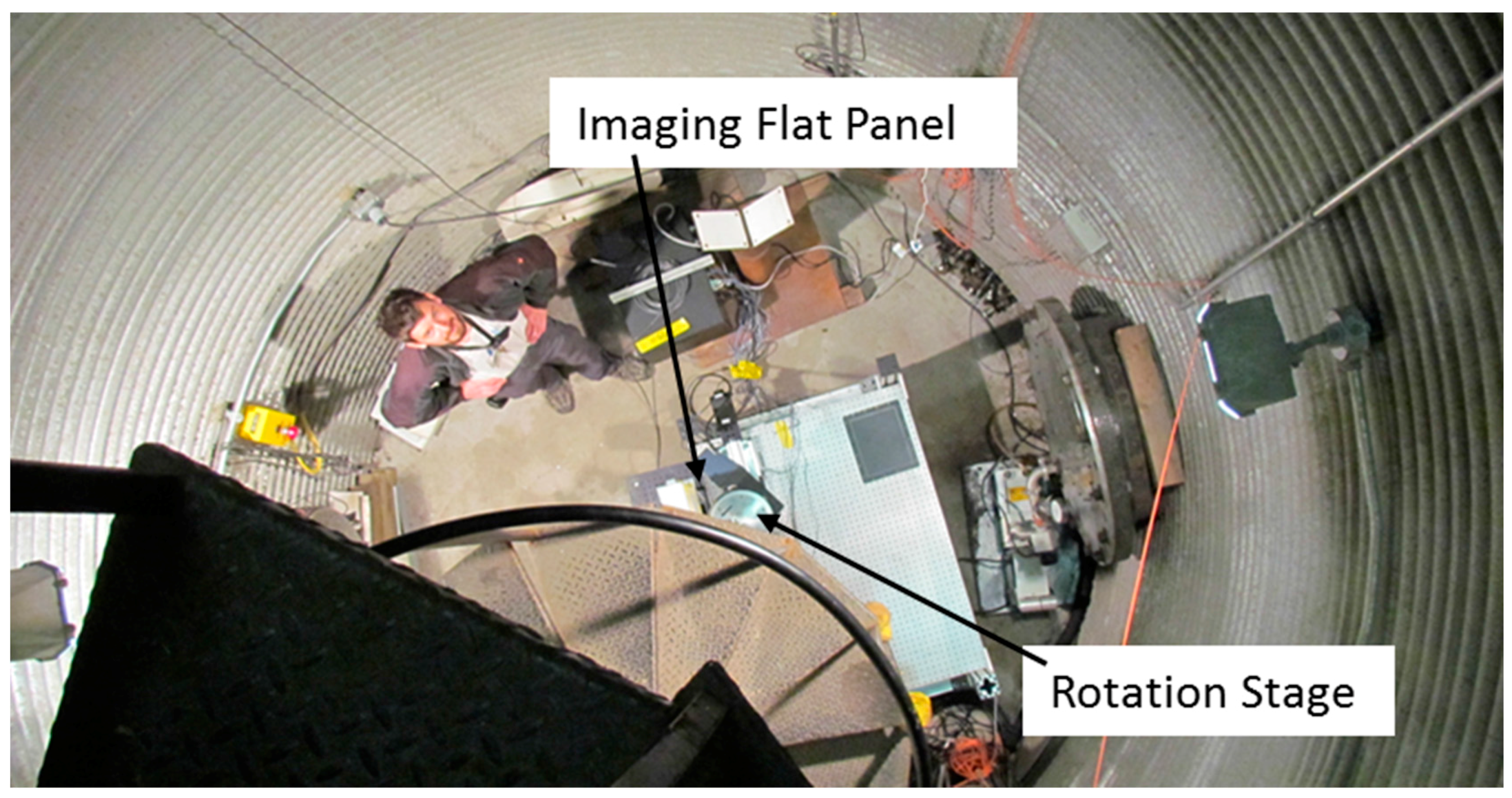
The main detector used for energy-resolved neutron imaging was developed by A. Tremsin [38,39,40] with early demonstrations on nuclear fuels [44]. See Table 2 for some technical details of the detector. Pixel- or event-centroiding means assigning a detection event to a detector location based on the center of gravity of a group of pixels triggered by the same neutron, thus providing spatial resolution better than the size of detector pixels. This approach was recently implemented for energy-resolved neutron imaging and is reported in this same issue. Besides the instrument cave with source-sample distances ranging from ~6.5 to ~11.5 m, FP-05 offers a station with source-sample distances from ~58 to 61 m (the “Silo”). The cave and silo are connected by a ~47 m long, 76 cm (30 inches) diameter evacuated pipe with borated polyethylene beam scrapers. At this station, the collimated beam has diverged to cover ~80 cm diameter. This can be utilized for imaging with a large field of view using e.g., amorphous silicon imaging detectors with scintillators or a camera viewing a scintillator via a mirror. Figure 5 shows the view from the top of the 60 m station.
Due to the longer flight path length, this station can be also used for high neutron-energy-resolution resonance measurements using the same collimation system shown in Figure 4, albeit without spatial resolution or imaging capability. A 500 MHz event rate detector with 55 photomultiplier tubes viewing 55 10B loaded liquid scintillator volumes is installed at that station [45]. The efficiency values reported by Yen et al. [45] are 95%, 85%, 71% for 10, 100, 1000 eV neutron energies. This is far superior to the efficiency of the MCP glass, that is quoted as 50% and 70% at 25 meV (thermal neutrons) and 5 meV (cold neutrons) [38] (see also a more recent evaluation of the efficiency [46]). For epi-thermal neutrons (>0.4 eV), the MCP efficiency is in the percent range and essentially zero for keV neutrons.
With the 10B detector, selected regions of a sample could be aligned within a small (0.1–1 mm) neutron beam to increase the available neutron energy range for resonance analysis, after bulk tomographic characterization with the typical ~2.5 cm diameter beam and MCP detector. The liquid scintillator detector with neutron resonance analysis of superior quality could then be used to e.g., characterize the chemical nature of an inclusion detected by tomography.
Neutron resonance based methods probing the properties of the phonons within a solid and thus connecting nuclear physics with solid state physics [47] were demonstrated at LANSCE in the past, e.g., temperature measurements [48], including during dynamic events [49], or the discrimination between alloying elements being contained in the host matrix or forming nano-clusters [50]. J-PARC [51] and ISIS [42] also have performed neutron resonance temperature measurements. These methods can be applied with this setup after selecting a region of interest from a radiographic or tomographic characterization, e.g., an inclusion or the most homogeneous volume within a sample to measure temperature or chemistry most reliably. Scanning of a slice of a sample characterized with bulk tomography with a small beam is also possible, using the translation and rotation stages of the imaging setup, providing increased isotope density resolution and energy range at the price of spatial resolution of only ~0.1–1 mm diameter, depending on the chosen collimation. However, due to the superior efficiency and large area of the 10B detector (compared to the MCP-based imaging detector), the majority of transmitted neutrons can be captured and even tomography of selected slices might be possible in the future.
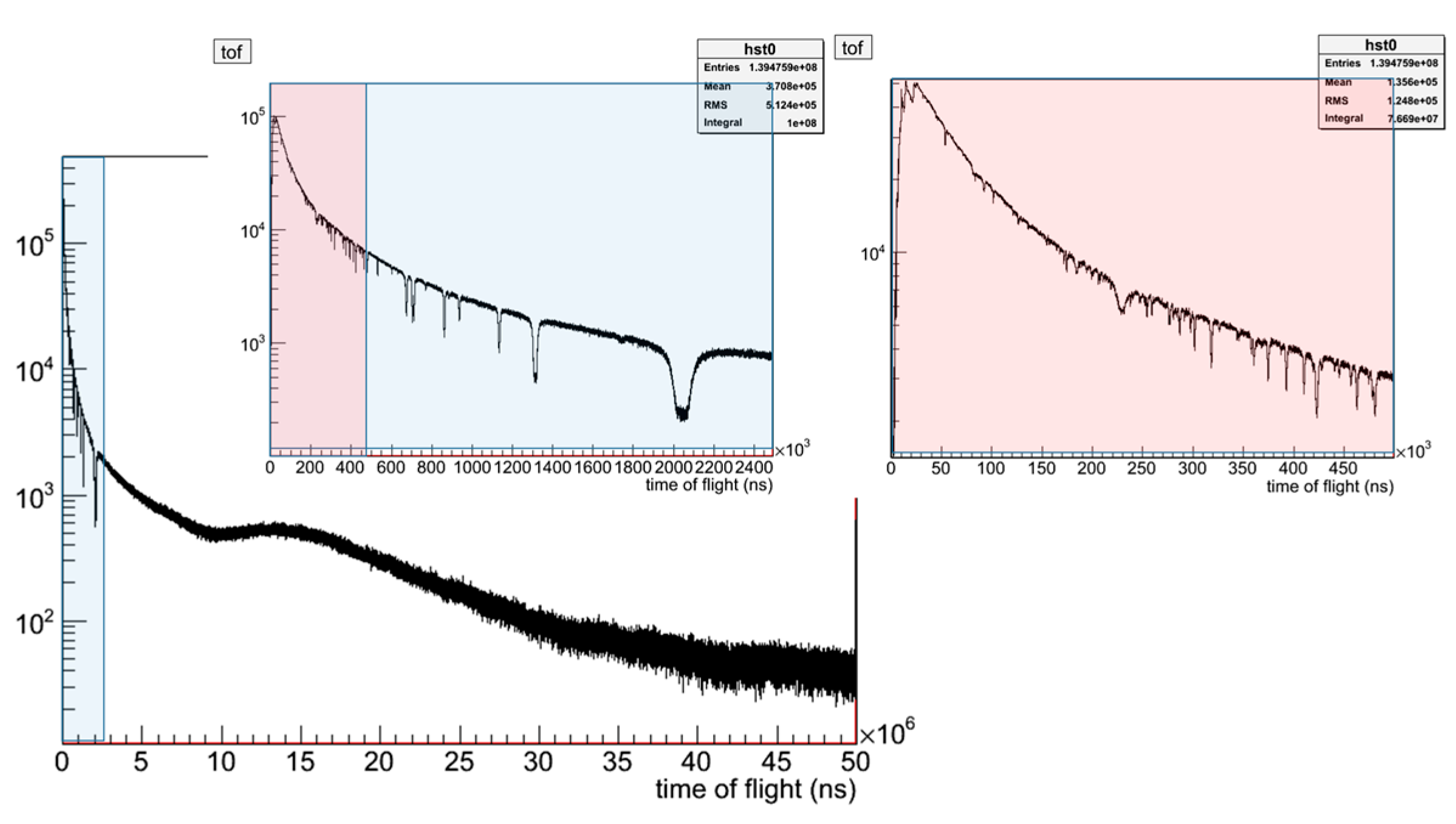
Figure 6 shows some sample data of the liquid scintillator detector at the 60 m silo station. The resonance observed at ~60 µs corresponds to a neutron energy of ~500 eV, illustrating the greatly extended energy range accessible with the detector. Note that the detector is not properly calibrated at this time and the data shown below are raw data, i.e., neither normalized nor background corrected, which are forthcoming activities.

3.2. Data Processing

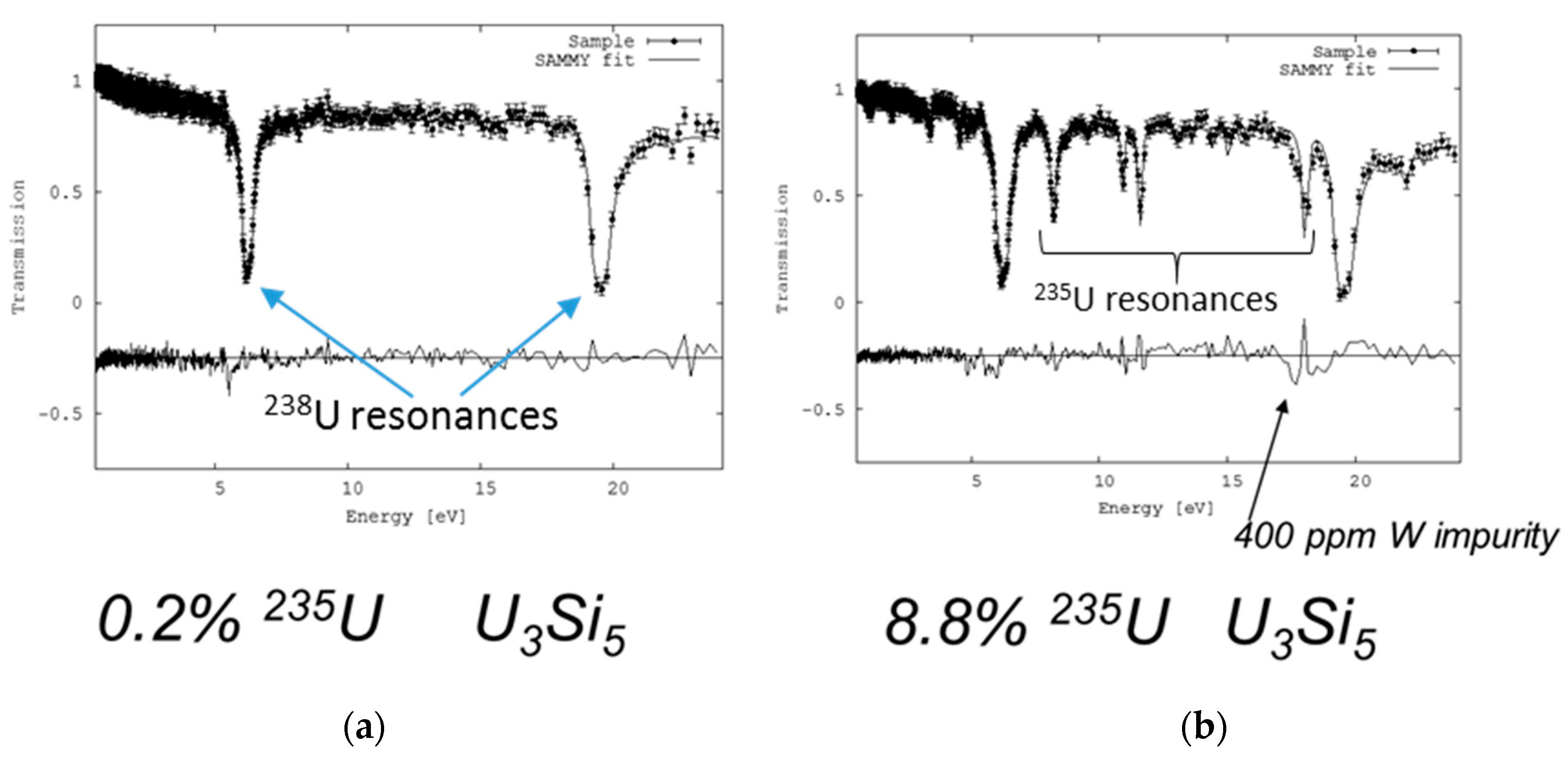
For non-energy-resolved neutron radiography, i.e., radiography using the integrated radiograph of cold, thermal and epi-thermal neutrons, pixel-by-pixel normalization with open beam radiographs is used to correct for intensity and detector response variations. For energy-selective neutron imaging, a much narrower neutron energy-band is selected by neutron time-of-flight cuts on the full spectrum, covering only the ~0.5 eV resonance of a given isotope. This same energy range is used for the normalization to open beam images. For quantitative energy-resolved neutron imaging, the transmission data recorded by the pixelated imaging detector for each pixel can be processed similar to a cross-section measurement, i.e., background corrected and normalized for each energy bin of the incident intensity and then analyzed with cross-section analysis codes such as SAMMY [52]. Utilizing the typically accurately known cross-section data of the isotopes, areal densities for multiple isotopes present in the sample can be determined. Such fitting can include neutron energy ranges from 0.5 eV to 100 eV with the present setup, thus covering multiple resonances. Fitting of multiple resonances is similar to Rietveld analysis of diffraction data, where multiple overlapping diffraction peaks are fit with fractions of each individual peak constrained by the computed structure factor and the peak positions constrained by the unit cell parameters. In resonance analysis, the cross-sections (‘intensities’) and energies (‘positions’) of neutron resonances are known and kept fixed, with only the common scale factor determined by the areal density refined. Figure 7 provides examples of such fits from data of U3Si5 nuclear fuel pellets with different enrichment levels. The difference in enrichment levels is visible by the differences in the depth of the 235U resonances (additional resonances in the right graph). A peak in the difference curve of the more highly enriched sample originates from the 18.6 eV resonance of tungsten, which is present as a ~400 ppm contamination in the more highly enriched fuel per chemical analysis, illustrating the sensitivity of the neutron method. Selecting a rectangular region of ~100 pixels on the centerline of a fuel pellet allowed measurement of the enrichment level to within 0.1% of the nominal value with an exposure time of ~45 min. Using radiographs with intensities replaced by areal density values from the cross-section analysis as input for tomographic density calculations allows a measurement of the mass in each voxel of the tomographic reconstruction. This allows, in turn, the density in g/cm3 for each isotope present to be calculated. In solids, this can be used to measure enrichment levels. In gases, energy-resolved neutron imaging provides a method to measure partial gas pressures as demonstrated by Tremsin et al. [53]. This work also demonstrates identification of the chemistry of different objects using energy-selective neutron imaging.

3.3. Application Examples

The majority of the research on flight-path 5 is funded by the U.S. Department of Energy’s Nuclear Energy program because neutrons, both for imaging and diffraction, are a unique probe to interrogate entire nuclear fuel pellets. Neutrons provide rich information on parameters ranging from crystallographic parameters (e.g., atomic positions, thermal motion parameters, strains), to meso-scale parameters (e.g., dislocation densities), to micro-structural features (e.g., weight or volume fractions of phases, grain orientation distribution or texture), to macroscopic features (e.g., dimensions, voids, cracks, isotope densities). Furthermore, the ability to penetrate shielding containers offers the opportunity to conduct this characterization on highly radioactive materials, ultimately providing detailed characterization of the same specimen pre- and post-irradiation. Pulsed neutrons, such as provided by the LANSCE spallation neutron source, provide distinct benefits over the continuous neutron flux provided by a reactor source. The Advanced Post-Irradiation Examination (APIE) efforts at LANL have developed novel techniques, such as energy-resolved neutron imaging described here and applied both novel and established techniques, such as neutron diffraction, to nuclear fuel forms ranging from ceramic fuels (oxides, nitrides, carbides, silicides) to metallic fuels (transmutation fuels, CONVERT fuels).
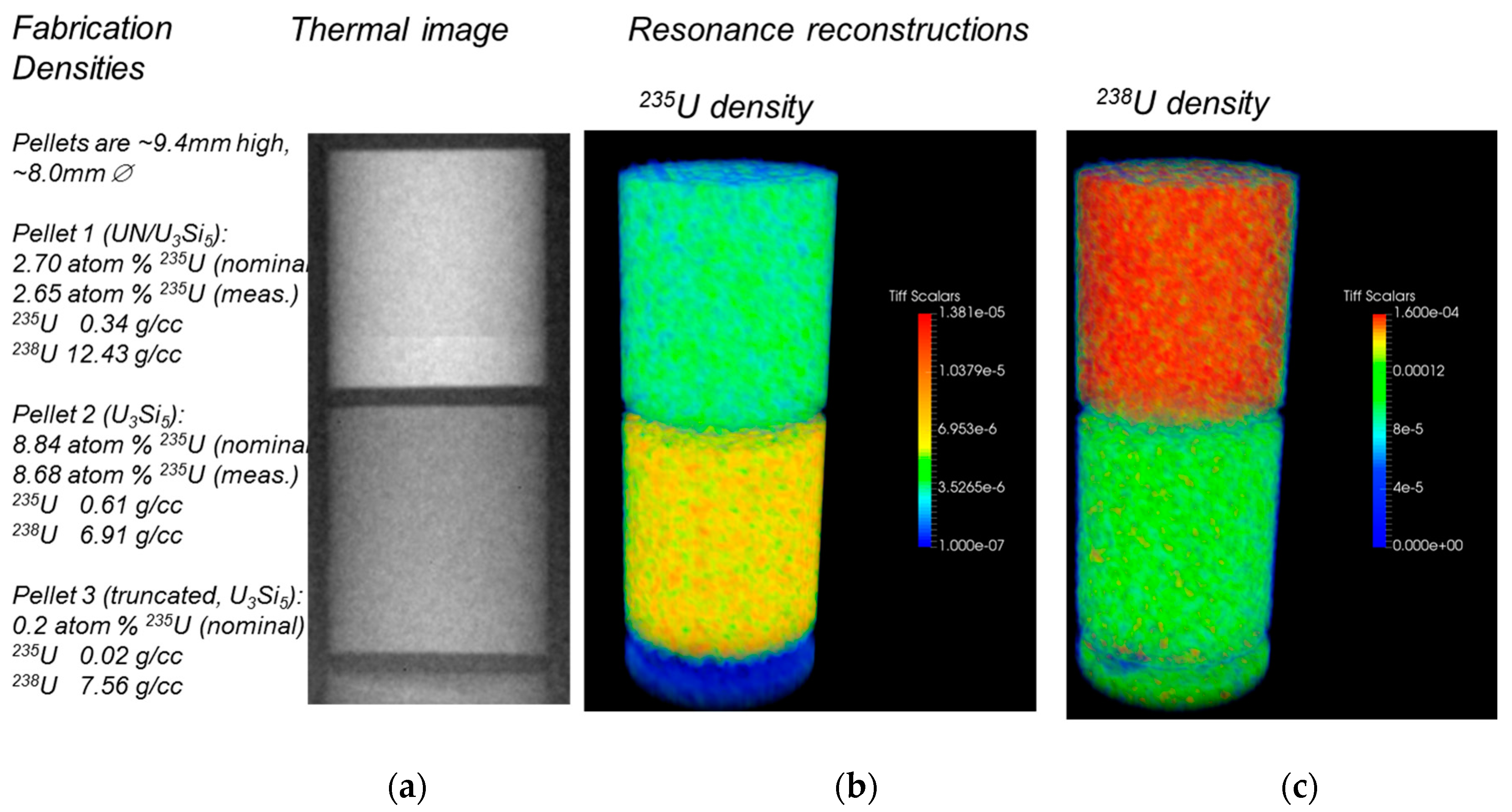
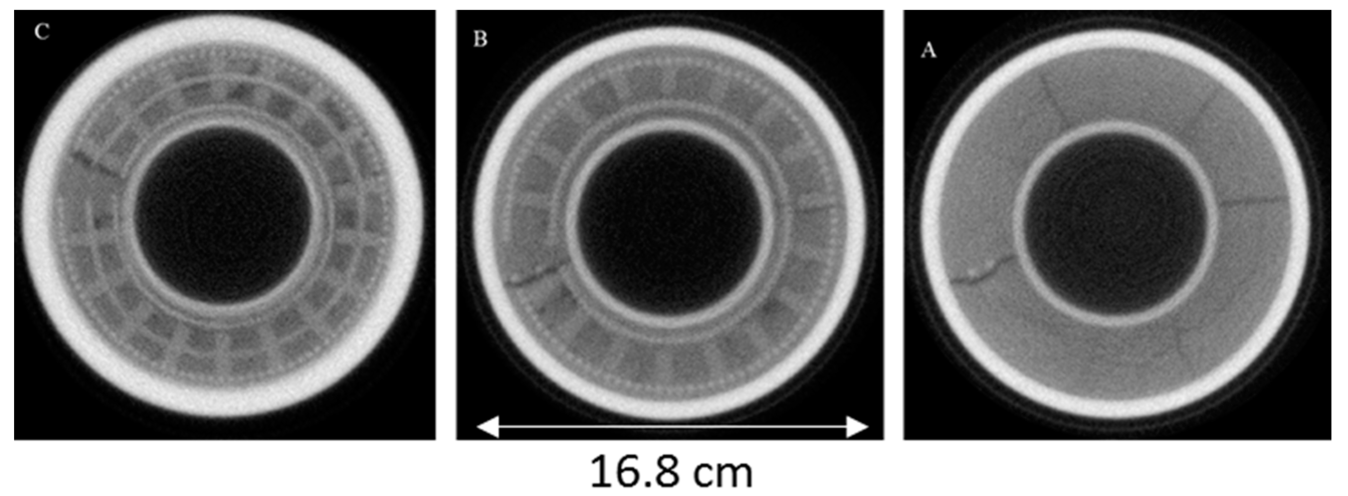
As an example of the thorough characterization outlined above, investigations on UN/U-Si composite fuels are shown in Figure 8, providing 3D isotope densities in UN/U3Si5 and U3Si5 pellets, with different enrichment levels, encapsulated in a stainless steel container. The average enrichment levels measured by neutron resonance transmission analysis are within 0.1% of the nominal enrichment levels. While characterization with thermal neutrons, as shown in Figure 8a, does not allow distinguishing the highest (8.8%) and lowest (0.2%) enrichment level pellets due to the overall attenuation being also affected by the UN/U3Si5 ratio, the reconstruction of the isotope density of 235U clearly (Figure 8b) allows that distinction. Figure 7 gives examples of the neutron transmission fits on which the reconstruction is based. Neutron diffraction, performed in mm slices along the axis of the samples, complements the characterization by energy-resolved neutron imaging and provides micro-structural information such as texture and volume fractions of crystallographic phases not available from neutron imaging.
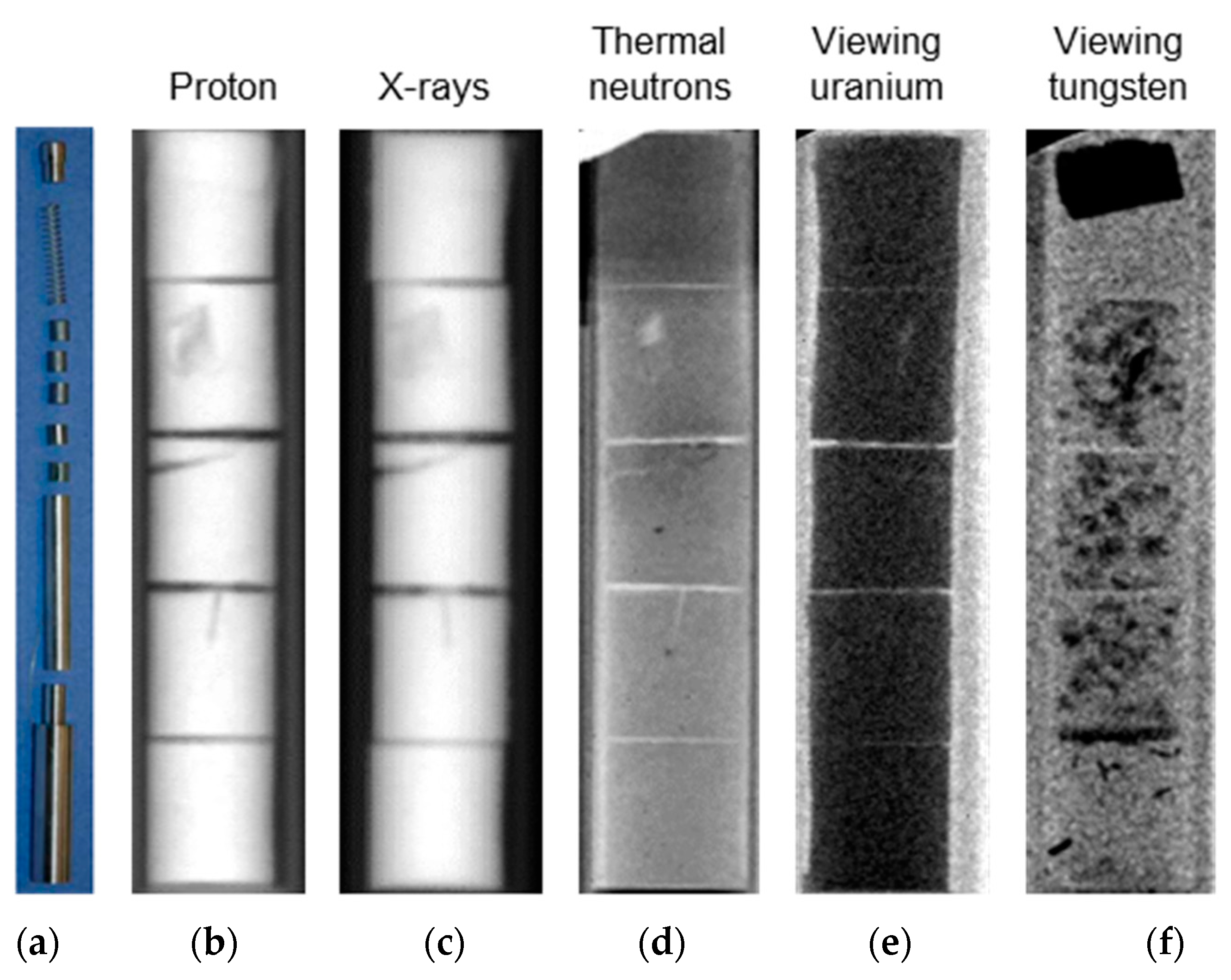
Figure 9 illustrates the differences of the radiography modalities available at LANL on depleted uranium-oxide (dUO2) fuel pellets inside a steel cladding: The interaction of protons and X-rays with matter are both to a first approximation governed by the atomic number, Z, of the atoms (number of electrons for X-rays and number of protons in nucleus for protons) and the radiographs obtained with 800 MeV protons and 450 keV X-rays are similar. Neutrons provide a different contrast mechanism from the nuclear interaction of the radiation with the atoms in the sample. While thermal neutrons complement characterization by X-rays and protons, only the resonance imaging with the epithermal neutrons allows one to unambiguously identify and quantify the distribution of specific isotopes. The fuel pellet on the top of all radiographs had a tungsten wedge embedded while the others had W filings mixed in with the dUO2 powder prior to sintering. Only the epithermal neutron imaging viewed at the 18.6 eV tungsten resonance allows visualization of the distribution of the tungsten, while protons, X-rays and thermal neutrons do not even provide an indication that tungsten is present.
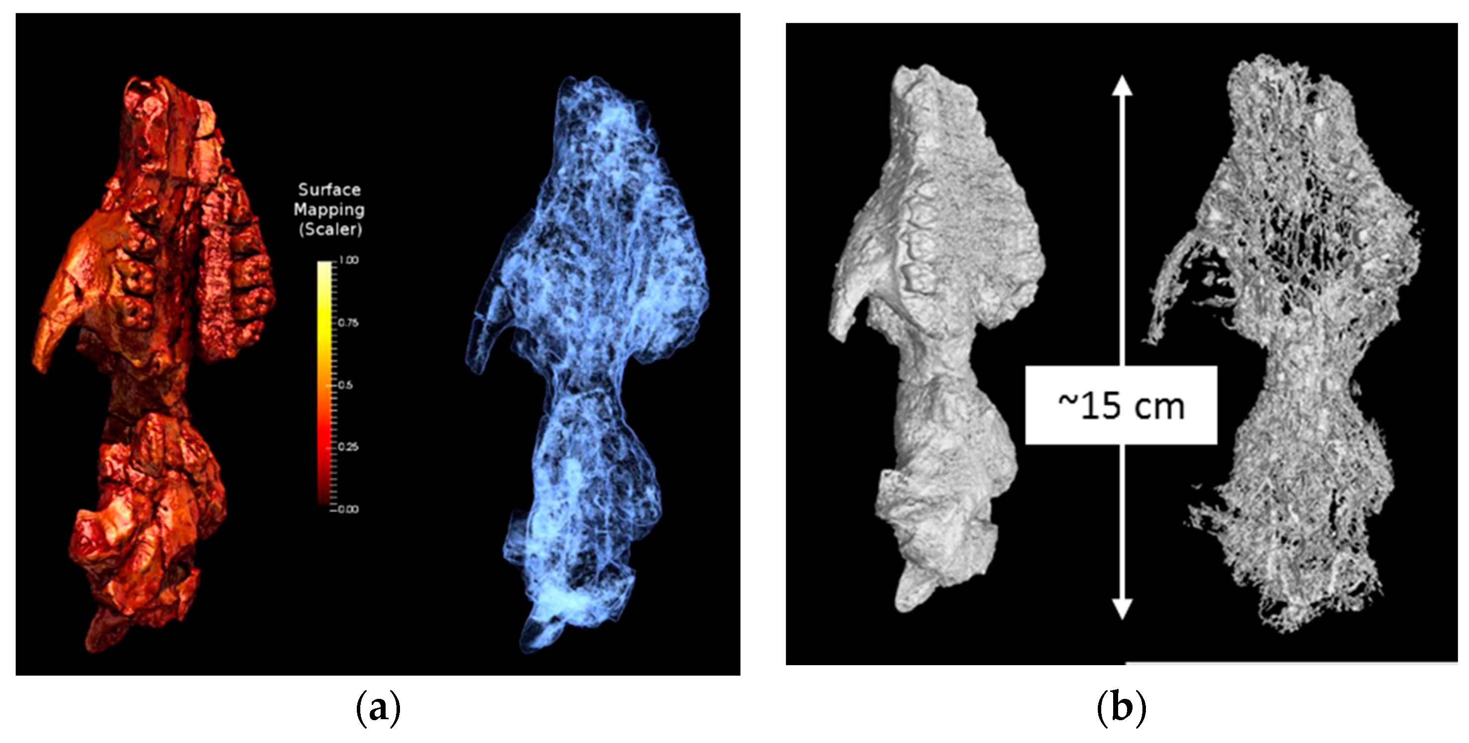
Besides research related to nuclear fuels, in recent years characterization of scintillator crystals was a significant part of the research portfolio at FP-05. The results of these efforts are reported in several publications [55,56,57]. Furthermore, the unique capabilities of energy-resolved neutron imaging for single crystal characterization were applied to characterize natural gold single crystals [58]. In an effort partially supported by the New Mexico Consortium and DOE/NNSA science campaigns, LANL was able to characterize fossilized skulls with both neutron and hard X-ray CT. This aids LANL in continuing algorithm development and cross-comparing different probes on the same specimen. For the paleontology community, neutron imaging with neutron energies covering both moderated (cold, thermal, epi-thermal) and unmoderated (fast) neutrons provides valuable insight on samples with limited X-ray contrast, too thick for X-ray CT, or containing minerals with elements (e.g., iron or uranium minerals) that obscure lower attenuation materials from X-ray interrogation. As an example, for the fossil characterization conducted on Flight Path 5, Figure 10 compares thermal neutron CT with hard X-ray CT. Having both data sets available, originating from different contrast mechanisms, provides information for the paleontology community not available from a single data set.
Data analysis techniques, in particular tomographic reconstruction algorithms, providing a combined reconstruction of both data sets while taking into account differences in the underlying physics that leads to the differing contrasts, are required as such combined studies become more common. A similar analysis problem exists with the nuclear fuel data sets collected by Tremsin et al. [44] using energy-selective neutron imaging which were also characterized by 450 keV X-ray and 800 MeV proton radiography [54], leading to three separate CT data sets of identical samples (Figure 9).
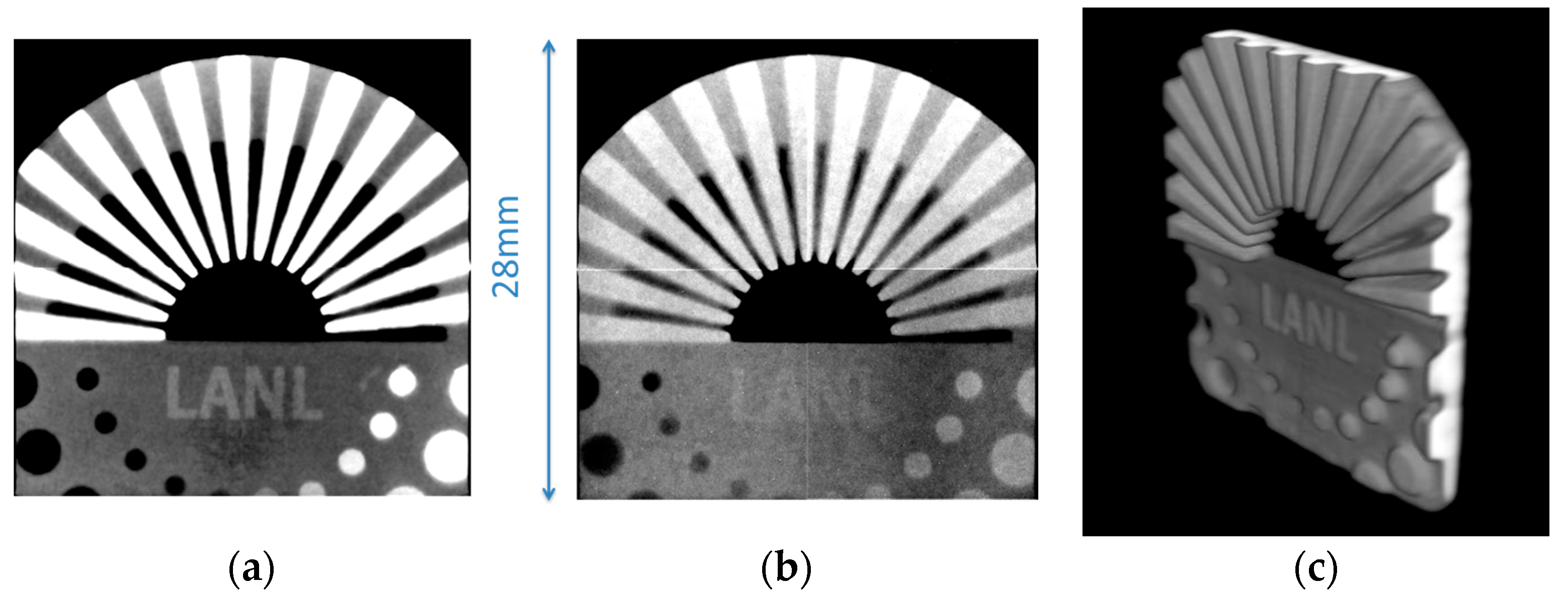
To further illustrate the unique material characterization potential of combining cold and thermal neutron radiography with neutron resonance tomography, an additively manufactured (3D printed and sintered) disk-shaped tungsten object was characterized. The object has a diameter of 40 mm. Figure 11 shows the thermal neutron radiograph with various inhomogeneities appearing as shadows around the LANL logo (e.g., a dark spot below the word “LANL” and a bright spot left of the top most white circle). Both features are almost invisible in the radiograph from neutron energies around the strong (~45 kbarn) W resonance at 18.6 eV. This finding indicates that the brighter spot in the thermal image (stronger thermal neutron attenuation) originates from atoms with a stronger thermal neutron attenuation than the tungsten matrix. This makes residues of the hydrogen-containing binder material from the additive manufacturing process a potential candidate as an explanation for this spot. The availability of element specific radiographs or CT reconstructions greatly enhances the data available to interpret features found during material characterization.

3.4. Water Transport in Plants

The Lujan center neutron beam lines have also been used to support studies of water transport in plants. Despite decades of research and method development [59,60,61], non-destructive, in vivo measurements of water uptake and flow in plants are challenging because of the opacity of soil and of the plant tissues. Especially challenging is the intricate nature of the water transport system. In this system, fine roots are connected to microbial networks supporting the plants and opposing pressure gradients in adjacent tissues are responsible for water uptake from the soil and delivery of carbohydrates produced in the leaves.
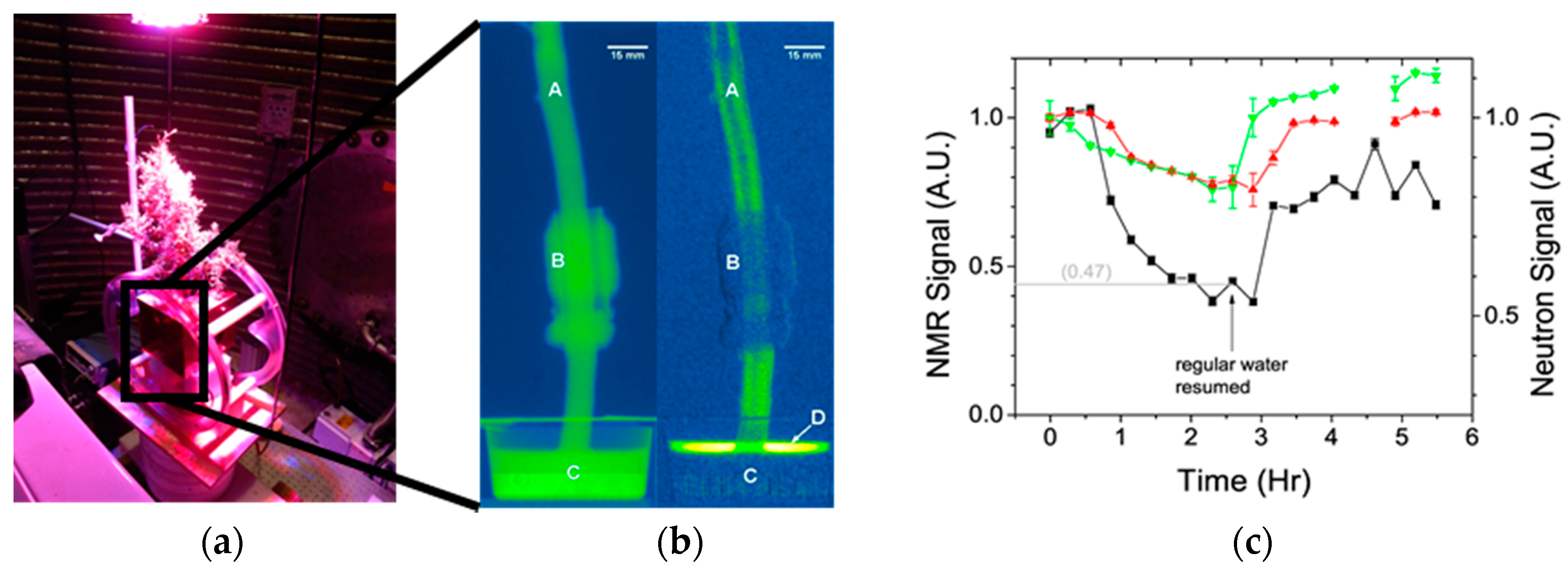
Using the contrast properties of D2O and H2O in neutron imaging combined with the ability of plants to take up D2O as normal water, we used neutron radiography to image water transport in pine and juniper branches and detect water exchange between the adjacent tissues responsible for water uptake and carbohydrate delivery, see Figure 12 [62]. Imaging was conducted simultaneously with low field NMR to calibrate the NMR system.
In Figure 12, the photograph on the left shows the NMR coil for producing the magnetic field surrounding the branch that is placed in the neutron beam coming from the right. The neutron detector is on the left. Middle, left: the neutron image shows the branch (A), the NMR detector solenoid on the branch (B) and the cup holding heavy water (C). Middle, right: Subtracting subsequent neutron images from the first creates difference images that can be used for analyzing water movement in the branch and provides a direct measurement for the water uptake rate from the cup (D). Right: The signal intensity of both the NMR (black squares) and the neutrons decline when D2O reaches the measurement point and recover after watering with H2O. From the time lag in signal strength between measurement below the NMR coil (green diamonds) and above the NMR coil (red triangles) flow rates can be calculated and by comparing the slope of signal decay and the time needed for reaching saturation, water distribution between different tissues can be determined. Figure modified from [62].
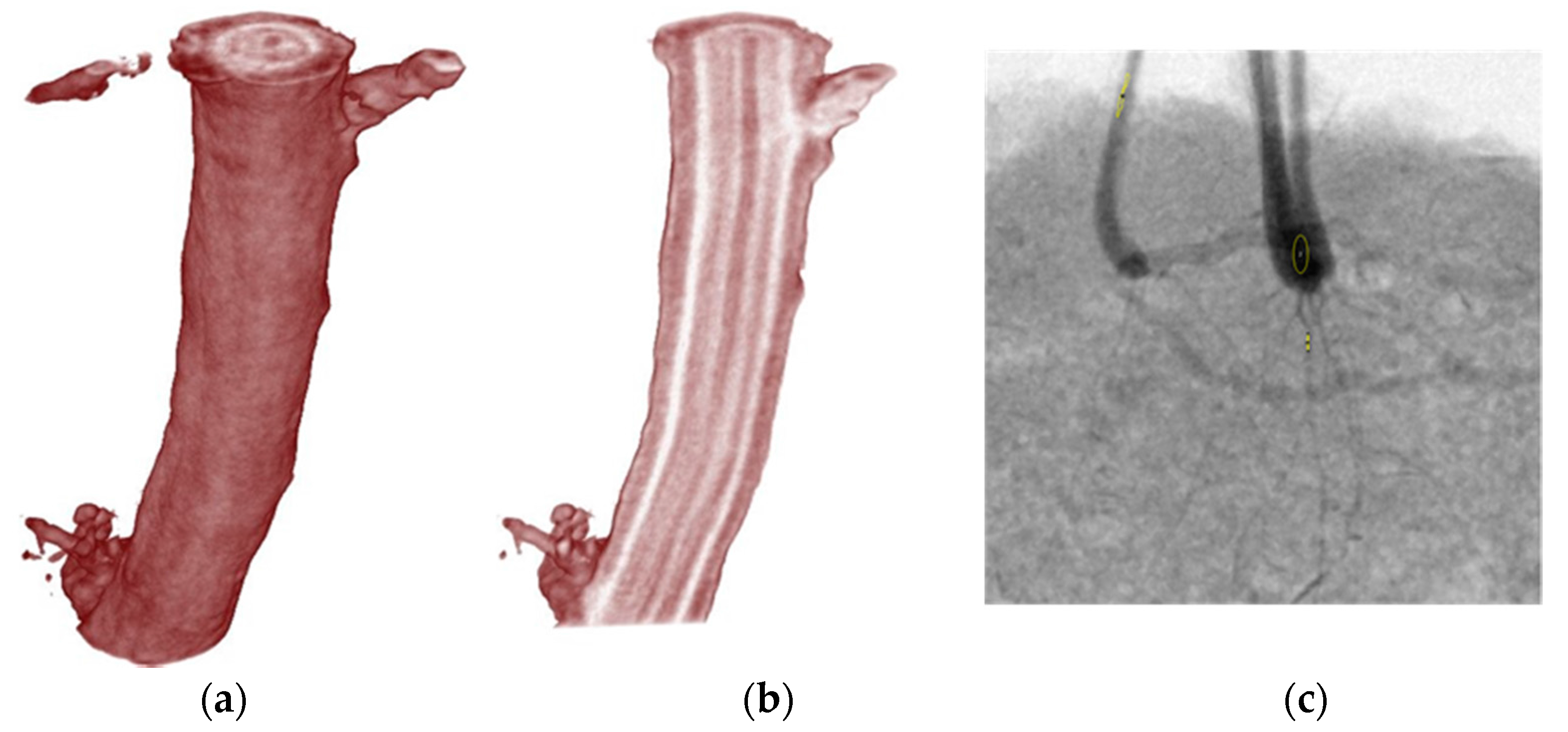
Using similar D2O labeling and neutron imaging through soil, we have imaged water uptake and water content in plant roots using the MCP detector [38,39,40] on FP-05 at the 8 m station, see Figure 13. Such measurements give an advantage of non-destructive functional characterization of roots and soil-root interactions enabling linking root anatomy to function in situ. Efforts are underway to use the 1FP-11 cold neutron imaging to improve the contrast in these studies.

3.5. Large Area Thermal Neutron Imaging

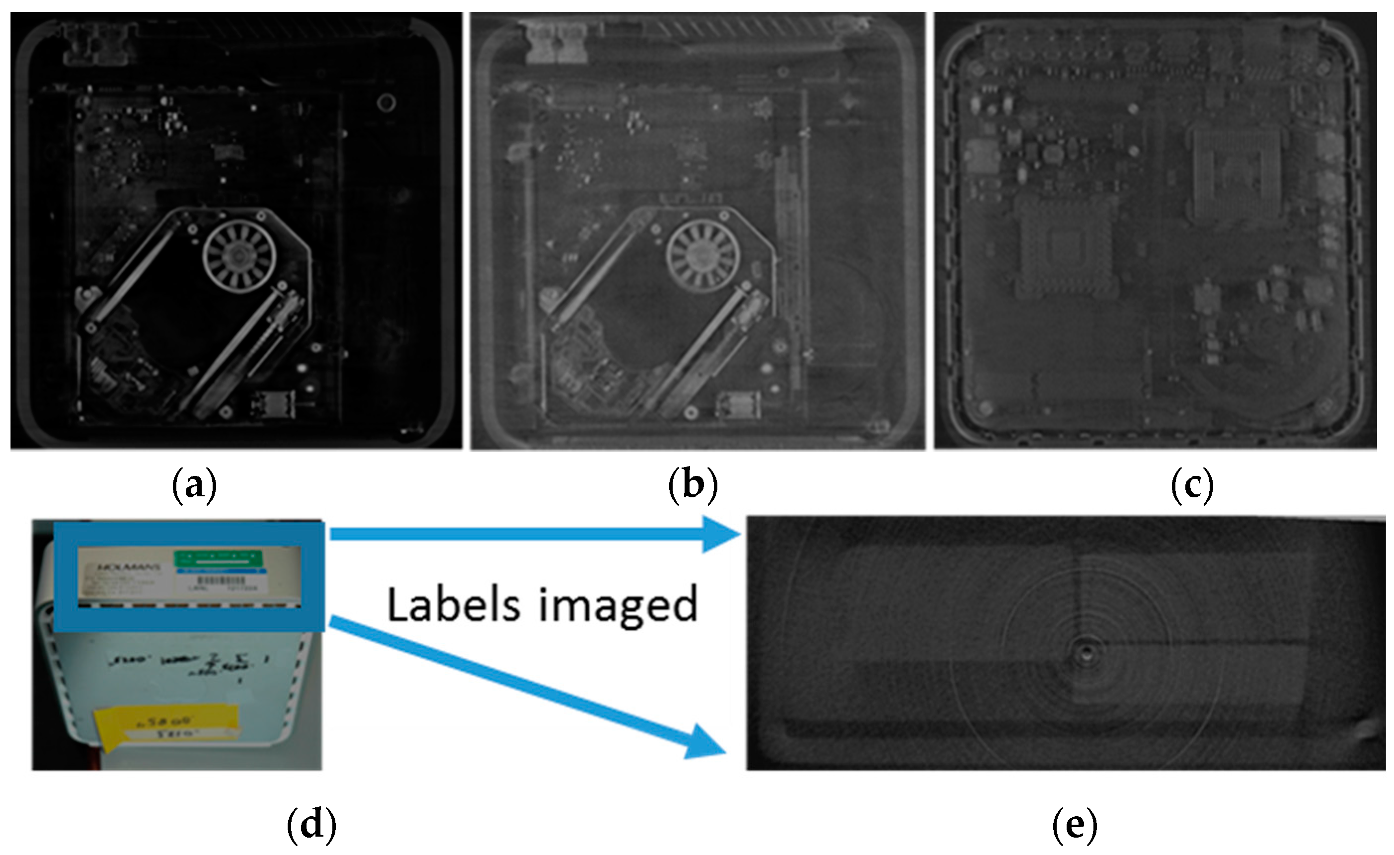
An example of thermal neutron images taken at the 60 m station on 1FP-05 is shown in Figure 14, a Mac Minicomputer (200 mm × 200 mm × 36 mm) was CT scanned using a flat panel with a GadOx scintillator screen. For comparison, the Mac mini was also characterized with 6 MeV X-rays. Due to the difference in contrast mechanisms between neutrons and X-rays with circuit board components, motors, labels, etc. thermal neutron imaging can provide better contrast in many areas than X-ray imaging, or the lower-energy techniques previously described.

4. High-Energy Neutron Imaging

High-energy neutron imaging has been pursued, in general, with two main goals in mind, (1) to perform energy-selective (TOF-gated) imaging to use resonance-structure-related cross section differences to resolve concentrations of the elements, C, N and O, useful in explosives detection [63,64,65], for example and (2) imaging features shielded by high-Z, materials that are often dense and may be thick [66] and thus are intractable to image even with very high-energy (>1 MeV) X-rays. In addition to these uses, energy-selective imaging can be used to investigate the performance of scintillators and imaging systems as functions of incident neutron energy in order to understand characteristics and to choose or develop optimal components for neutron imaging. [67,68,69]

4.1. The WNR 4FP60R Flight Path Imaging

The Target 4 neutron production target is a 3.0 cm diameter by 7.5 cm long tungsten cylinder mounted with the long axis aligned with the 100 Hz, 800 MeV proton beam that is directed at 8 degrees from horizontal. For the 60 degree right flight path, the target is viewed, at an angle of 60 degrees with respect to the beam direction. The neutron beam is typically defined and controlled by a 1.9 m long, steel neutron shutter extending from 4.6 to 6.5 m with an opening of 8.1 cm diameter that views the entire neutron production target. The result is that the neutron source has dimensions of about 3 cm in the vertical direction and about 7 cm in the horizontal direction. Without smaller defining apertures, the L/D ratio at 21 m is 700 vertical and 300 horizontal. Three sets of collimators follow the neutron shutter with substantial shielding around each. This provides a well-collimated beam and low background environment at the sample position, with several collimator choices to reduce backgrounds by limiting the field of view as needed. Measurements have shown that thermal neutron backgrounds are small as long as no large amount of moderating material is placed directly in the neutron beam.
Substantial shielding consisting of high-density magnetite concrete blocks surrounds the sample position and the entire flight path to reduce radiation dose rates to personnel to levels below 2 mR/h maximum. The shielding was modeled and designed using the Monte Carlo code MCNP6 [70] to accommodate the largest neutron beams and to account for large samples that are highly scattering in the forward direction as well as highly attenuating samples that produce higher radiation levels at the sample position.
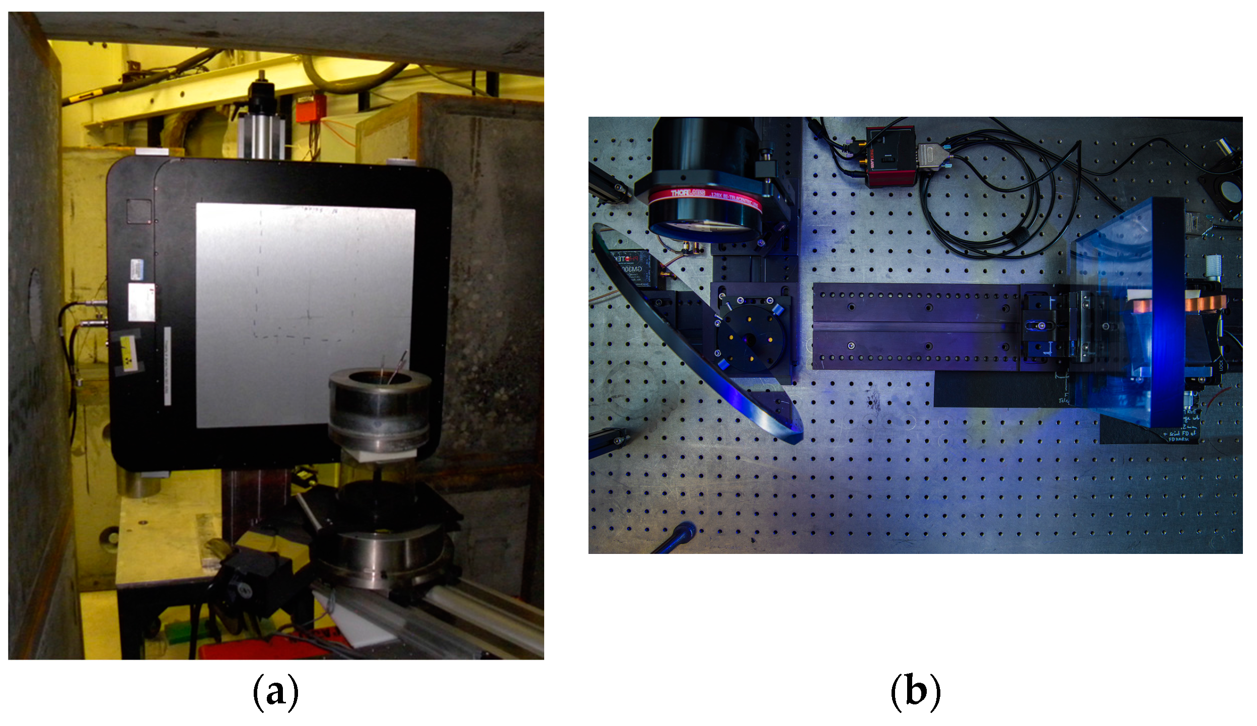
Imaging equipment typically consists of a precision rotation stage mounted on a translation stage for CT imaging. These stages are mounted on a lift table for vertical positioning. An a-Si flat panel (Perkin Elmer, now Varex Imaging, model 1621 High-Sensitivity) [71] with 40 × 40 cm active area with an attached 2.5 mm thick PP + ZnS:Cu scintillator from RC Tritec [72] has demonstrated maximum light output with good contrast, although thinner scintillators provide better spatial resolution. Polypropylene with ZnS:Cu (and Ag) was first produced commercially by Industrial Quality, Inc. 30 or more years ago. In high-energy neutron imaging at LANSCE in the 1990’s it was observed to have the highest light output of any scintillator tested. In 1993, Yoshii and Mya [73] also examined the characteristics of ZnS:Ag plus polypropylene for fast neutron imaging. We tested both Cu-doped and Ag-doped ZnS and found that the good match between the green light from ZnS:Cu and the peak spectral response of a-Si flat panels resulted in about 3 times greater sensitivity than observed with ZnS:Ag. At our request, RC Tritec researched and began production of these scintillators. Spatial resolution approaching the pixel size of 200 microns has been demonstrated for resolution gauges near the scintillator. For imaging through thick uranium, features of 2 mm can be reliably observed. Figure 15 shows a flat panel detector mounted in the inner shielding on 4FP-60R.
Two different TOF CCD camera configurations have been used to perform fast time-gated imaging to select specific neutron energy ranges. Only one energy range can be selected per exposure but the time gating can range from sub nanosecond to an entire beam macro pulse, typically 1.8 microseconds. Princeton Instruments Pi-Max 4 cooled iCCD camera [74] and Spectral Instruments, Inc. model 830 cooled CCD camera [75] with a PhoTek model 375 MCP image intensifier [76] have been used. A pellicle mirror at 45 degrees is used to reflect the image to the camera that is out of the neutron beam and behind shielding blocks from the sample. In spite of the well-collimated and shielded beam line, energetic radiation events are observed in the radiation sensitive CCD cameras. An optical table with the camera system components is shown at right in Figure 15.
Scintillators for fast-gated, energy-selective imaging are typically fast plastic such as those supplied by Saint Gobain [77] and Eljen Technologies [78]. We recently performed studies of the energy response of scintillators over a range of thicknesses, from 1 mm to 20 mm and for different phosphors. Spatial resolution has been studied as functions of incident neutron energy and scintillator thickness and will be presented in [79]. ZnS scintillator, both Ag-doped and Cu-doped that we used, decay too slowly for TOF measurements on a microsecond time scale.
As with all forms of radiography, the more sensitive the detector, the less dose required to obtain an image and the less intensity required from the radiation source. For this reason, we are actively working on the development of improved neutron converter/scintillator screens, especially for high-energy imaging but also for the other energy ranges. Both time integrating (slow) and fast-time gated detectors have applications.

4.2. Flat Panel Imaging System Results

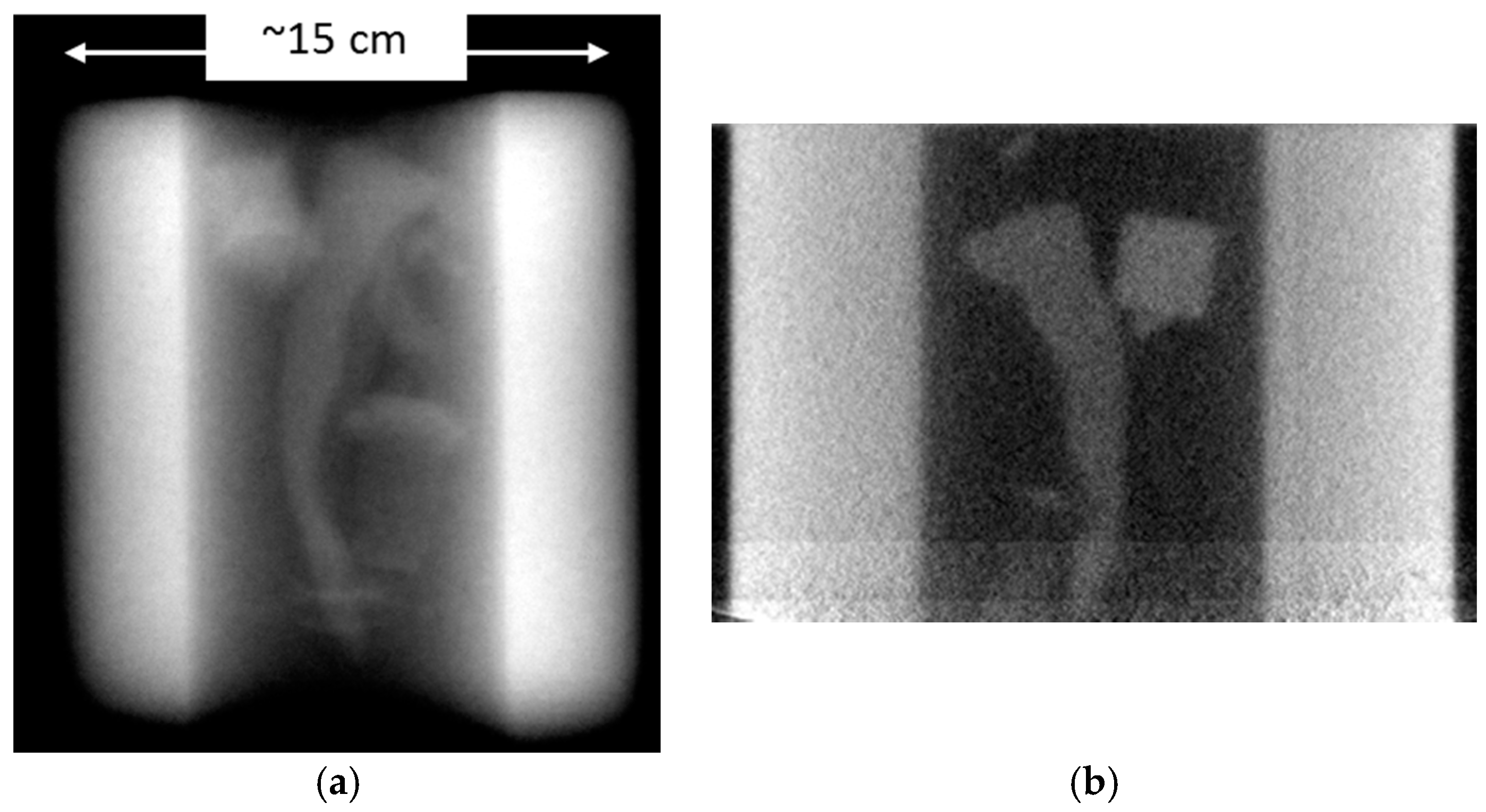
A Perkin Elmer a-Si flat panel industrial imager with a ZnS:Cu + PP screen 2.5 mm thick is currently used for high-energy neutron radiographs and CT scans. Figure 16 shows inner details of the cathode pictured in Figure 15a. In Figure 17, some “New Mexico” objects imaged inside a thick uranium cylinder are shown. The slow scintillator decay time (>2 µs) does not allow neutron energy selection but produces good contrast for the LANSCE high-energy neutron beam. Figure 17a is a radiograph of the cylinder, while Figure 17b is a CT slice clearly showing a cross section of the aluminum alloy chili pepper and the double “fool’s gold” crystal.
Imaging though thick uranium is difficult even with very high energy X-rays and intractable if low-Z elements are to be imaged.
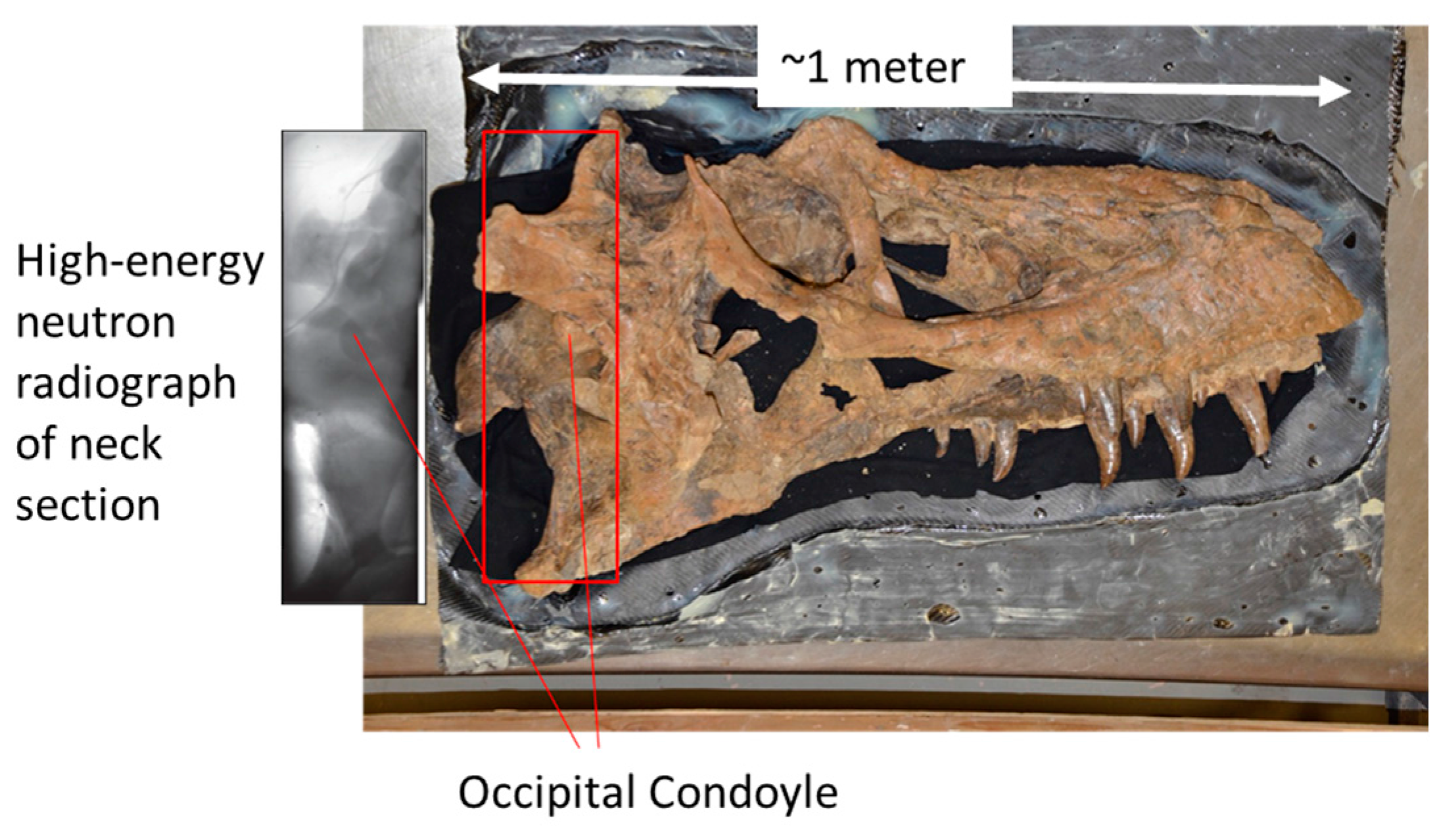
In collaboration with the New Mexico Museum of Natural History and Science (NMMNHS), an effort was undertaken to image a large tyrannosauroid fossil skull that was found in the Four Corners area of New Mexico. The goal was to combine X-ray and high-energy neutron imaging to observe features of the anatomy that may be preserved inside the skull. The skull and a radiograph of one end of the fossil are shown in Figure 18. Many interesting internal features are observed such as, nascent teeth in the jaw, the cranial endocast or braincase, sinuses and pathways of blood vessels and nerves. These potentially aid paleontologists in inferring information about metabolism, growth, and, with multiple specimens, about evolution of a species.
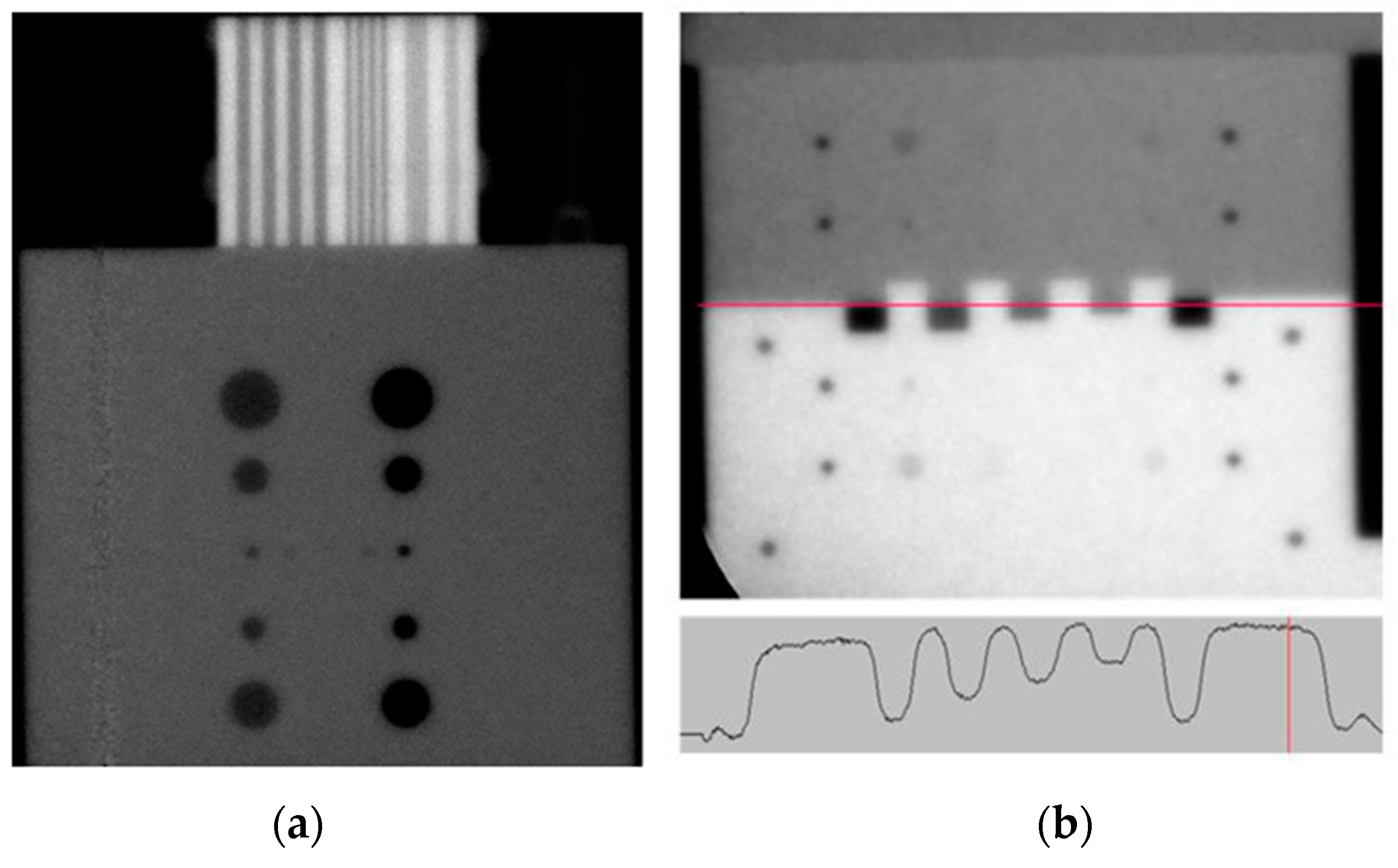
Figure 19 demonstrates the spatial resolution and contrast achieved with phantoms that include a tantalum and polyethylene line pair gauge, holes in a polyethylene plate and various features in a steel, aluminum and polyethylene phantom created by LLNL staff.

4.3. High-Energy Neutron Time-of-Flight Imaging System Results

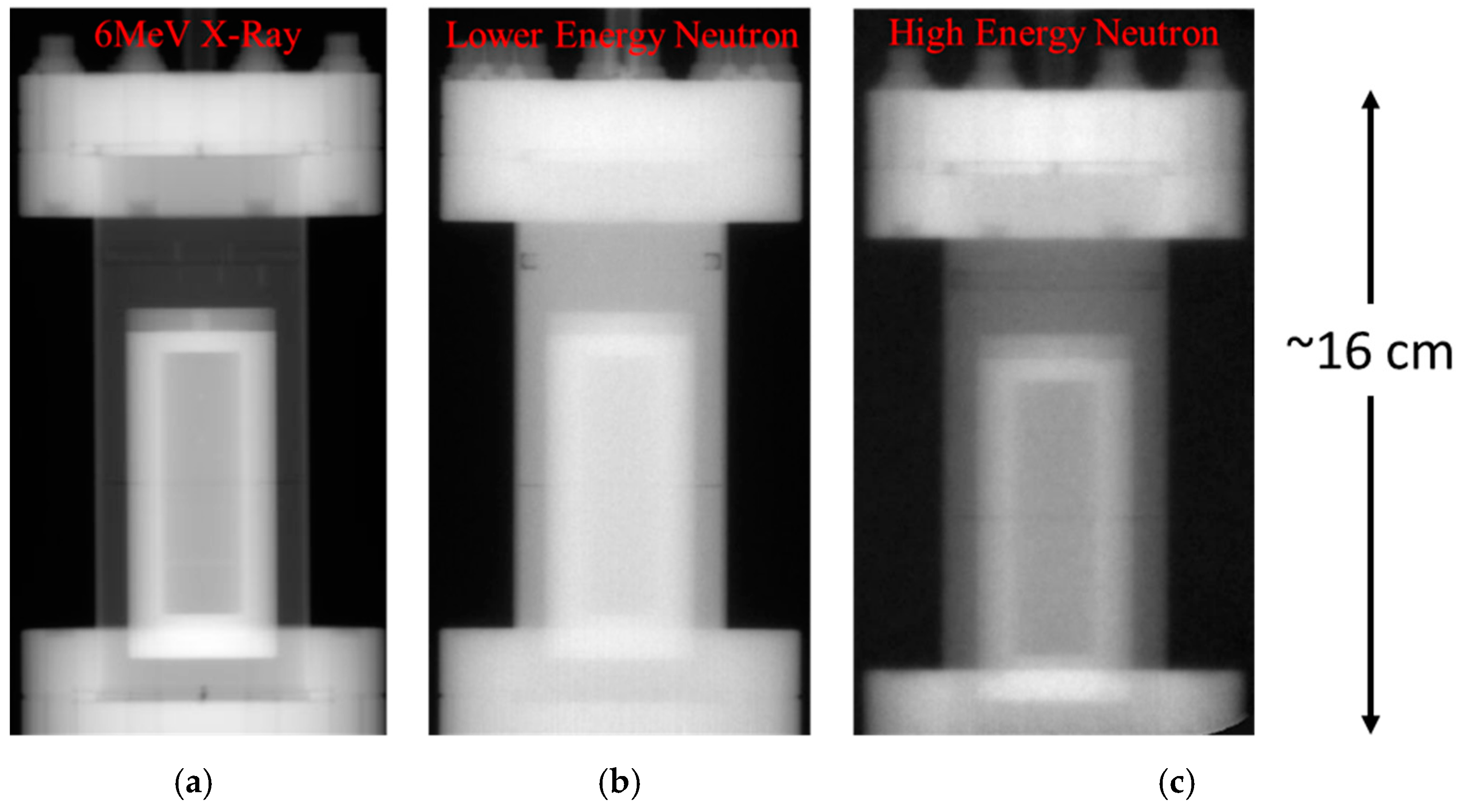
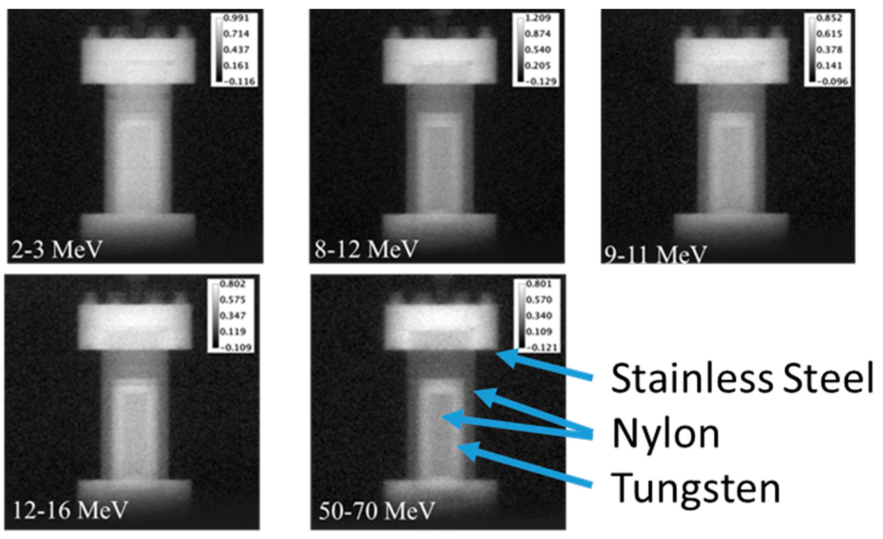
Using TOF imaging, we obtained energy gated images of a phantom consisting of various metal and polymer components. Three of these images are shown in Figure 20. Despite the X-ray image being done with a mature, highly optimized facility, the neutron images show good quality despite being a first attempt. Figure 21 shows images taken at multiple neutron energy regions. The TOF camera system can provide scattering rejection in neutron imaging, as well as energy-selective images as shown here. Further details of this system are given in References [80,81].

4.4. Multi-Modal and Multi-Energy Imaging

Dual-energy X-ray imaging is well known as providing more information than single-energy imaging. Combined X-ray imaging and neutron imaging likewise can make visible features that are not visible in a single image alone. Such multi-energy and multi-modal imaging offer paths to more powerful imaging capabilities that can be quantitative and can provide important new insights in imaging of challenging objects.
An example from some time ago is the use of high-energy neutron imaging at two-different energies, or combined neutron and gamma-ray imaging to determine the hydrogen content in getter materials [82]. Using the prompt gamma-flash when the proton beam hits the neutron production target and later energetic neutrons with fast timing of MCP’s means that such dual measurements could be made simultaneously with a two camera arrangement. This can provide a fast and powerful measurement technique for determining hydrogen content in objects. This is but one example of techniques that can be developed for particular imaging challenges.

5. Cold Neutron Imaging at Target 1, Flight Path 11 (ASTERIX)

Typical neutron imaging is based on the neutron attenuation of the imaged object, showing regions of high versus low absorption. However, neutron imaging becomes more challenging if the studied objects have low neutron attenuation cross sections or if there are features with low absorption contrast. In such cases, the quantum mechanical, wave-like, neutron properties of thermal and cold neutrons can be used to advantage to perform so called “phase-contrast” or “refraction-enhanced” neutron imaging. Phase contrast imaging (PCI) with neutrons was first demonstrated in 1980 by Schlenker et al. using perfect crystal interferometry to image ferromagnetic domains [83]. This approach relies on extremely collimated and monochromatic beams resulting in very low intensities and long measurement times. Following advances in synchrotron X-ray phase contrast imaging, Allman et al. demonstrated a neutron phase propagation method in 2000 [84] and Strobl, et al. described further studies of edge effects in 2009 [85]. The propagation method employs a typical in-line imaging geometry with sufficient distance between the object and detector to enable the influence of the propagation of neutron phase on intensities to be resolved. Using this approach, polychromatic neutron beams and less tightly defined incident beam collimations can be exploited to measure neutron phase contrast images with much shorter exposure times. We have employed this relatively simple and high-intensity technique that works well with polychromatic beams such as those used at LANSCE.

5.1. Lujan Center 1FP-11 Description

At LANSCE, the Lujan Center’s ASTERIX beamline (1FP-11) views a liquid hydrogen moderator providing “cold neutrons” (0.3 to 3 meV or wavelengths of ~5 to 15 Å) that are especially suited for performing phase-contrast imaging. A 6 cm × 6 cm neutron guide transports the cold neutrons 15.1 m from the moderator to a variable aperture which can be opened to maximize flux for cold neutron radiography or reduced to provide a more collimated beam for neutron phase contrast imaging. For phase contrast measurements, typical aperture sizes of the source range from 0.5 mm × 0.5 mm to 5.0 mm × 5.0 mm. The source to detector distance is 5.0 m resulting in L/D values ranging from 1000 to 10,000. The sample position can be easily adjusted by moving the sample positioning goniometer along a rail to facilitate comparable absorption contrast measurements with the sample in contact with the detector and phase contrast measurements with the sample separated from the detector, typically by ~0.5 m.

5.2. Phase Contrast Imaging Using a High Spatial Resolution Micro Channel Plate (MCP) Detector

High resolution phase contrast images of a sample consisting of Pb fishing weights suspended by Al wire on a thin Al plate were measured using a MCP detector with 55 μm pixel size. A 1 mm × 1 mm aperture was used with a source to detector distance of 5.0 m and an object to detector distance of 0.45 m. Gamma ray contributions to the image from the spallation source were discriminated based on timing. Figure 22 shows images taken with the Pb and Al objects for which the cold neutron transmission is > 98%. The highly collimated beam required relatively long exposure times: both the absorption contrast and phase contrast images were measured for 13 h. The absorption contrast is very poor, while the phase contrast image displays excellent definition of edges, interfaces and internal defects in the materials.

5.3. Phase Contrast Imaging of Shielded Objects Using a–Si Detector

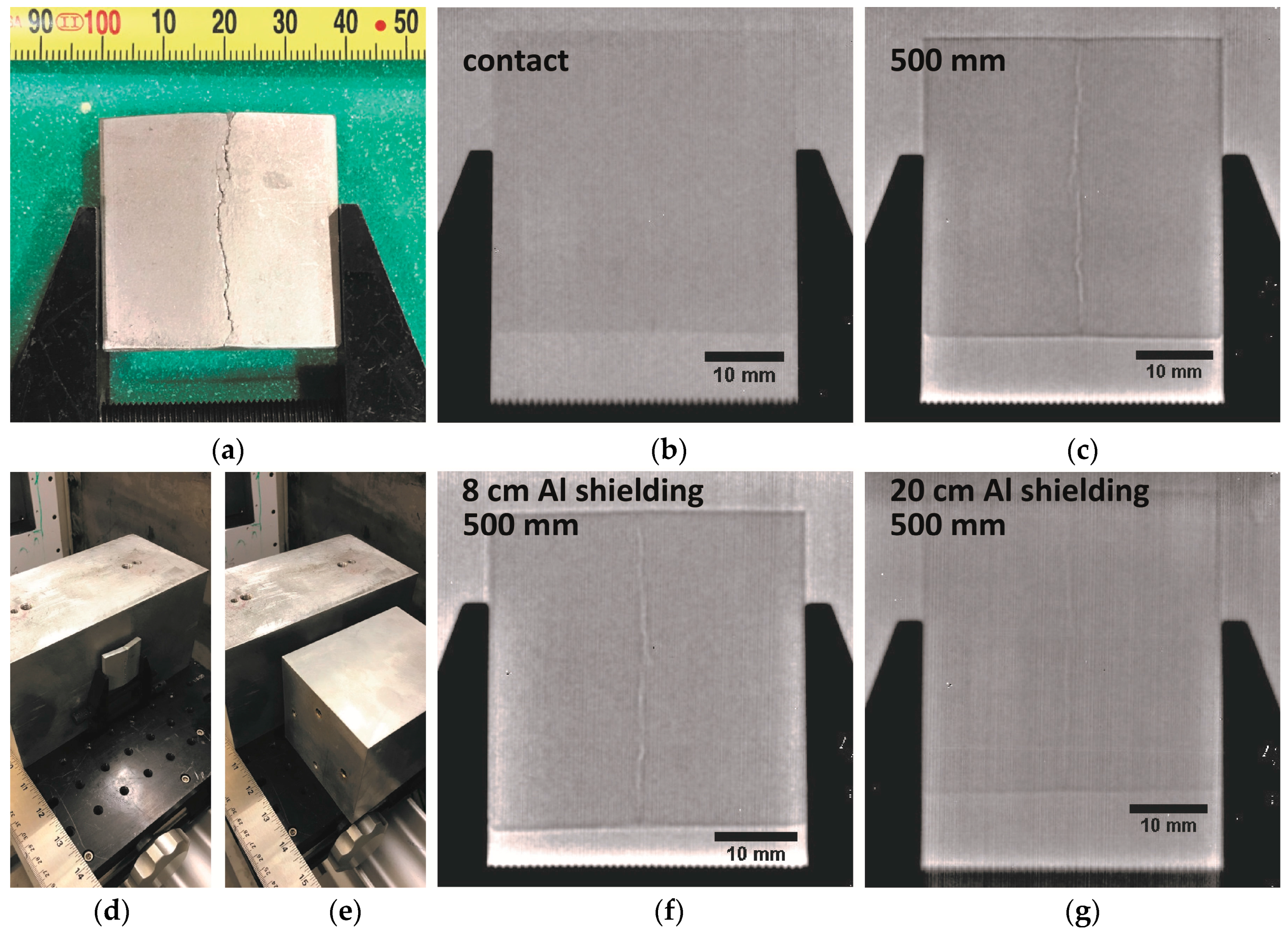
Phase contrast images of a 38 mm × 38 mm × 5 mm Al plate with a ~150 μm wide crack were measured using a 6Li:ZnS scintillator coupled to an a-Si flat panel detector. The resolution of the detector was 127 μm, comparable to the width of the crack and all measurements were performed with a 5 mm × 5 mm aperture size and 5 m between aperture and detector (Figure 23). In an absorption contrast image obtained with the sample in contact with the detector, the outline of the Al plate was visible but negligible absorption contrast prevented the hairline crack from being observable (Figure 23, top center). For phase contrast images, the sample was moved 0.5 m upstream from the detector. The large aperture size was chosen to maximize flux but, in the phase contrast configuration, at the expense of a low, ~0.5 mm, geometric resolution resulting in blurring of the object. Despite a geometric blur larger than the feature size, phase contrast images clearly enhance the outer edges of the Al plate and the crack (Figure 23, top right). In this configuration, the crack could be visualized with exposure times as short as 1 min which will facilitate future phase-sensitive tomography experiments. The sample was also measured surrounded by Al shielding of varying thickness to demonstrate the ability to detect small features or defects deep within a material. The crack was clearly visible surrounded by 8 cm of Al (Figure 23, bottom center) and remained detectable with shielding by up to 20 cm of Al (Figure 23, bottom right). For greater thicknesses, additional blurring originating from scattering events in the shielding material obscured the phase contrast of the crack.

6. Conclusions

The broad energy range covered by LANSCE neutron sources and the imaging techniques that have been and are being developed for cold, thermal, resonance and high-energy neutrons show great promise. Properties including spatial resolution, isotope sensitivity, uncertainties for density measurements and so forth are being improved. These properties depend on experimental parameters that are often being changed for different imaging situations. Systematic investigations of spatial resolution and contrast, as well as optimization of imaging flight paths are ongoing. Thus, it is difficult to provide a fixed set of specifications for LANSCE imaging parameters, rather a range of values must be given.
Imaging and quantification of individual isotopes in complex samples is a powerful tool that can advance both science and manufacturing. High-energy neutron imaging addresses imaging challenges requiring highly penetrating radiation and cold neutron imaging enables thin objects to be studied with good contrast, even transparent materials can be imaged in great detail using neutron phase contrast methods. Laser-driven neutron sources show great promise, having small source dimensions, short pulse lengths and directed beams. The TRIDENT laser was recently decommissioned but other laser-driven neutron source options are being studied. In addition, lower-cost, compact neutron sources are being developed that make neutron imaging both portable and available to more users for wider application, see for example [86]. Identifying and developing new applications of these techniques will be essential for the future.

Acknowledgments

This work was performed under the auspices of the U.S. Department of Energy (DOE) under Contract No. DE-AC52-06NA25396 and has benefited from use of the LANSCE accelerator facility supported under the same contract. The support of the U.S. Department of Energy, Office of Nuclear Energy Nuclear Technology Research and Development program is gratefully acknowledged by SCV, AST, KJM, ATN and JTW. SCV, ASL and AST acknowledge funding from the U.S. Department of Energy, National Nuclear Security Administration’s Nonproliferation Research and Development Program (NA-22) for funding of project LB15-V-GammaDetMater-PD3Jf. The plant imaging studies presented in this article were supported by the Laboratory Directed Research and Development program of Los Alamos National Laboratory under project number 20130442ER. The MCP imaging system was purchased with funds from a LANL PADSTE small equipment grant. The fossil imaging was funded in part by the New Mexico Consortium. Funds were provided to cover the cost of publishing in open access. NPB gratefully acknowledges funding for a summer research fellowship from LANL’s Seaborg Institute for Plutonium and Actinide Science. The loan by James Hall of the LLNL phantoms for high energy neutron imaging is gratefully acknowledged.

Author Contributions

For energy-selective imaging the active experimenters were: S.C.V., J.F.H., A.S.L., A.S.T., N.P.B., K.J.M., S.M.M., A.T.N., L.K.V. and R.O.N. For high-energy neutron imaging the active experimenters were: R.O.N., J.F.H., D.C.G., M.A.E., T.E.C., A.L.S., A.C.M., D.R.M., R.C.S. and N.M.W. For cold/phase contrast imaging, the active experimenters were: E.B.W., A.S.L., R.O.N., D.S.M., K.J.R., J.M. and J.F.H. The plant imaging team consisted of: S.A.S., S.C.V., A.S.L., L.T.D., M.A.E., M.W.M., J.F.H. and R.O.N. The fossil imaging contributors were: A.S.L., R.O.N. S.C.V., J.F.H., M.A.E., D.C.G., K.S. and T.E.W. The paper was written by R.O.N, S.C.V, E.B.W and S.A.S.

Conflicts of Interest

The authors declare no conflict of interest.

References

  1. Kalimann, H. Neutron Radiography. Research 1948, 1, 254–260. [Google Scholar] [CrossRef]
  2. Brenizer, J.S. A review of significant advances in neutron imaging from conception to the present. Phys. Procedia 2013, 43, 10–20. [Google Scholar] [CrossRef]
  3. Peter, O. Neutronen-Durchleuchtung. Z. Naturforschung 1946, 1, 551–559. [Google Scholar]
  4. Berger, H. Neutron Radiography; Methods, Capabilities and Applications; Elsevier: Amsterdam, The Netherlands; New York, NY, USA, 1965. [Google Scholar]
  5. Berger, H.; Iddings, F. Neutron Radiography—A State-of-the-Art Report. Nondestructive Testing Information Analysis Center Report NTIAC-SR-98-01. 1998. Available online: http://www.dtic.mil/get-tr-doc/pdf?AD=ADA355025 (accessed on 14 February 2018).
  6. Lehmann, E.H.; Vontobel, P.; Wiezel, L. Properties of the radiography facility NEUTRA at SINQ and its potential for use as European reference facility. Nondestruct. Test. Eval. 2001, 16, 191–202. [Google Scholar] [CrossRef]
  7. Calzada, E.; Gruenauer, F.; Mühlbauer, M.; Schillinger, B.; Schulz, M. New design for the ANTARES-II facility for neutron imaging at FRM II. Nucl. Instrum. Methods Phys. Res. Sect. A Accel. Spectrom. Detect. Assoc. Equip. 2009, 605, 50–53. [Google Scholar] [CrossRef]
  8. Kardjilov, N.; Hilger, A.; Manke, I.; Strobl, M.; Dawson, M.; Williams, S.; Banhart, J. Neutron tomography instrument CONRAD at HZB. Nucl. Instrum. Methods Phys. Res. Sect. A Accel. Spectrom. Detect. Assoc. Equip. 2011, 651, 47–52. [Google Scholar] [CrossRef]
  9. Hussey, D.S.; Jacobson, D.L.; Arif, M.; Huffman, P.R.; Williams, R.E.; Cook, J.C. New neutron imaging facility at the NIST. Nucl. Instrum. Methods Phys. Res. Sect. A Accel. Spectrom. Detect. Assoc. Equip. 2005, 542, 9–15. [Google Scholar] [CrossRef]
  10. Kaestner, A.P.; Hartmann, S.; Kühne, G.; Frei, G.; Grünzweig, C.; Josic, L.; Schmid, F.; Lehmann, E.H. The ICON beamline—A facility for cold neutron imaging at SINQ. Nucl. Instrum. Methods Phys. Res. Sect. A Accel. Spectrom. Detect. Assoc. Equip. 2011, 659, 387–393. [Google Scholar] [CrossRef]
  11. Sato, H.; Takada, O.; Iwase, K.; Kamiyama, T.; Kiyanagi, Y. Imaging of a spatial distribution of preferred orientation of crystallites by pulsed neutron Bragg edge transmission. J. Phys. Conf. Ser. 2010, 251, 012070. [Google Scholar] [CrossRef]
  12. Kiyanagi, Y.; Sato, H.; Kamiyama, T.; Shinohara, T. A new imaging method using pulsed neutron sources for visualizing structural and dynamical information. J. Phys. Conf. Ser. 2012, 340, 012010. [Google Scholar] [CrossRef]
  13. Kockelmann, W.; Zhang, S.Y.; Kelleher, J.F.; Nightingale, J.B.; Burca, G.; James, J.A. IMAT—A new imaging and diffraction instrument at ISIS. Phys. Procedia 2013, 43, 100–110. [Google Scholar] [CrossRef]
  14. RRDB Neutron Radiography Facilities. Available online: https://nucleus.iaea.org/RRDB/Content/Util /NeutronRadioGraphy.aspx (accessed on 14 February 2018).
  15. Lehmann, E.H. Neutron Imaging Facilities in a Global Context. J. Imaging 2017, 3, 52. [Google Scholar] [CrossRef]
  16. Lehmann, E.; Trtik, P.; Ridikas, D. Status and perspectives of neutron imaging facilities. Phys. Procedia 2017, 88, 140–147. [Google Scholar] [CrossRef]
  17. McDonald, T.E.; Brun, T.O.; Claytor, T.N.; Farnum, E.H.; Greene, G.L.; Morris, C. Time-gated energy-selected cold neutron radiography. Nucl. Instrum. Methods Phys. Res. Sect. A Accel. Spectrom. Detect. Assoc. Equip. 1999, 424, 235–241. [Google Scholar] [CrossRef]
  18. Kiyanagi, Y.; Kamiyama, T.; Iwasa, H.; Hiraga, F. Characteristics of a new type neutron radiography using time-of-flight method. Key Eng. Mater. 2004, 270, 1371–1375. [Google Scholar] [CrossRef]
  19. Silver, R.N. The Los Alamos Neutron Scattering Center. Physica B+C 1986, 137, 359–372. [Google Scholar] [CrossRef]
  20. Sachs, R.D.; Morris, R.A. Fail-Safe Neutron Shutter Used for Thermal Neutron Radiography; Los Alamos National Laboratory Report LA-6527, UC-38; U.S. Department of Energy Office of Scientific and Technical Information: Oak Ridge, TN, USA, 1976.
  21. Feiertag, T. Thermal Neutron Radiography at Los Alamos. In Proceedings of the Neutron Resonance Radiography Workshop, Los Alamos, NM, USA, 27–29 July 1987; Los Alamos National Laboratory Report, LA·UR-87-2474; Los Alamos National Laboratory: Los Alamos, NM, USA.
  22. Barton, J.P.; Bryant, L.E.; Berry, P.C. Multi-Purpose Neutron Radiography System. In Proceedings of the 5th World Conference on Neutron Radiography, Berlin, Germany, 17–20 June 1996. LA-UR-96-1975. [Google Scholar]
  23. King, N.S.; Ables, E.; Adams, K.; Alrick, K.R.; Amann, J.F.; Balzar, S.; Barnes, P.D., Jr.; Crow, M.L.; Cushing, S.B.; Eddleman, J.C.; et al. An 800-MeV proton radiography facility for dynamic experiments. Nucl. Instrum. Methods Phys. Res. Sect. A Accel. Spectrom. Detect. Assoc. Equip. 1999, 424, 84–91. [Google Scholar] [CrossRef]
  24. Borozdin, K.N.; Hogan, G.E.; Morris, C.; Priedhorsky, W.C.; Saunders, A.; Schultz, L.J.; Teasdale, M.E. Surveillance: Radiographic imaging with cosmic-ray muons. Nature 2003, 422, 277. [Google Scholar] [CrossRef] [PubMed]
  25. Morris, C.L.; Bacon, J.; Ban, Y.; Borozdin, K.; Fabritius, J.M.; Izumi, M.; Miyadera, H.; Mizokami, S.; Otsuka, Y.; Perry, J.; et al. Analysis of muon radiography of the Toshiba nuclear critical assembly reactor. Appl. Phys. Lett. 2014, 104, 024110. [Google Scholar] [CrossRef]
  26. Muon scans confirm complete reactor meltdown at Fukushima Reactor #1—ExtremeTech. Available online: https://www.extremetech.com/extreme/201706-muon-scans-confirm-complete-reactor-meltdown-at-fukushima-reactor-1 (accessed on 14 February 2018).
  27. Guardincerri, E.; Durham, J.M.; Morris, C.; Bacon, J.D.; Daughton, T.M.; Fellows, S.; Morley, D.J.; Johnson, O.R.; Plaud-Ramos, K.; Poulson, D.C.; et al. Imaging the inside of thick structures using cosmic rays. AIP Adv. 2016, 6, 015213. [Google Scholar] [CrossRef]
  28. Alvarez, L.W.; Anderson, J.A.; El Bedwei, F.; Burkhard, J.; Fakhry, A.; Girgis, A.; Goneid, A.; Hassan, F.; Iverson, D.; Lynch, G.; et al. Search for hidden chambers in the pyramids. Science 1970, 167, 832–839. [Google Scholar] [CrossRef] [PubMed]
  29. Morishima, K.; Kuno, M.; Nishio, A.; Kitagawa, N.; Manabe, Y.; Moto, M.; Takasaki, F.; Fujii, H.; Satoh, K.; Kodama, H.; et al. Discovery of a big void in Khufu’s Pyramid by observation of cosmic-ray muons. Nature 2017, 552, 386–390. [Google Scholar] [CrossRef] [PubMed]
  30. Gavron, A.; Morley, K.B.; Morris, C.; Seestrom, S.J.; Ullmann, J.L.; Yates, G.J.; Zumbro, J.D. High Energy Neutron Radiography. In Proceedings of the 5th International Conference on Applications of Nuclear Techniques, Heraklion, Greece, 9–15 June 1996. [Google Scholar]
  31. Claytor, T.N.; Taddeucci, T.N.; Hills, C.R.; Summa, D.A.; Davis, A.W.; McDonald, T.E.; Schwab, M.J. High-energy and thermal-neutron imaging and modeling with an amorphous silicon flat-panel detector. Appl. Radiat. Isot. 2004, 61, 579–584. [Google Scholar] [CrossRef] [PubMed]
  32. Lisowski, P.W.; Schoenberg, K.F. The Los Alamos neutron science center. Nucl. Instrum. Methods Phys. Res. Sect. A Accel. Spectrom. Detect. Assoc. Equip. 2006, 562, 910–914. [Google Scholar] [CrossRef]
  33. Lisowski, P.W.; Bowman, C.D.; Russell, G.J.; Wender, S.A. The Los Alamos national laboratory spallation neutron sources. Nucl. Sci. Eng. 1990, 106, 208–218. [Google Scholar] [CrossRef]
  34. Fernández, J.C.; Cort Gautier, D.; Huang, C.; Palaniyappan, S.; Albright, B.J.; Bang, W.; Dyer, G.; Favalli, A.; Hunter, J.F.; Mendez, J.; et al. Laser-plasmas in the relativistic-transparency regime: Science and applications. Phys. Plasmas. 2017, 24, 056702. [Google Scholar] [CrossRef] [PubMed]
  35. Guler, N.; Volegov, P.; Favalli, A.; Merrill, F.E.; Falk, K.; Jung, D.; Tybo, J.L.; Wilde, C.H.; Croft, S.; Danly, C.; et al. Neutron imaging with the short-pulse laser driven neutron source at the Trident laser facility. J. Appl. Phys. 2016, 120, 154901. [Google Scholar] [CrossRef]
  36. Roth, M.; Jung, D.; Falk, K.; Guler, N.; Deppert, O.; Devlin, M.; Favalli, A.; Fernandez, J.; Gautier, D.; Geissel, M.; et al. Bright laser-driven neutron source based on the relativistic transparency of solids. Phys. Rev. Lett. 2013, 110, 044802. [Google Scholar] [CrossRef] [PubMed]
  37. Ino, T.; Ooi, M.; Kiyanagi, Y.; Kasugai, Y.; Maekawa, F.; Takada, H.; Muhrer, G.; Pitcher, E.J.; Russell, G.J. Measurement of neutron beam characteristics at the Manuel Lujan Jr. neutron scattering center. Nucl. Instrum. Methods Phys. Res. Sect. A Accel. Spectrom. Detect. Assoc. Equip. 2004, 525, 496–510. [Google Scholar] [CrossRef]
  38. Tremsin, A.S.; Feller, W.B.; Downing, R.G. Efficiency optimization of microchannel plate (MCP) neutron imaging detectors. I. Square channels with 10 B doping. Nucl. Instrum. Methods Phys. Res. Sect. A Accel. Spectrom. Detect. Assoc. Equip. 2005, 539, 278–311. [Google Scholar] [CrossRef]
  39. Siegmund, O.H.; Vallerga, J.V.; Tremsin, A.S.; Mcphate, J.; Feller, B. High spatial resolution neutron sensing microchannel plate detectors. Nucl. Instrum. Methods Phys. Res. Sect. A Accel. Spectrom. Detect. Assoc. Equip. 2007, 576, 178–182. [Google Scholar] [CrossRef]
  40. Tremsin, A.S.; McPhate, J.B.; Vallerga, J.V.; Siegmund, O.H.; Feller, W.B.; Lehmann, E.; Dawson, M. Improved efficiency of high resolution thermal and cold neutron imaging. Nucl. Instrum. Methods Phys. Res. Sect. A Accel. Spectrom. Detect. Assoc. Equip. 2011, 628, 415–418. [Google Scholar] [CrossRef]
  41. Shinohara, T.; Kai, T.; Oikawa, K.; Segawa, M.; Harada, M.; Nakatani, T.; Ooi, M.; Aizawa, K.; Sato, H.; Kamiyama, T.; et al. Final design of the Energy-Resolved Neutron Imaging System “RADEN” at J-PARC. J. Phys. Conf. Ser. 2016, 746, 012007. [Google Scholar] [CrossRef]
  42. Tremsin, A.S.; Kockelmann, W.; Pooley, D.E.; Feller, W.B. Spatially resolved remote measurement of temperature by neutron resonance absorption. Nucl. Instrum. Methods Phys. Res. Sect. A Accel. Spectrom. Detect. Assoc. Equip. 2015, 803, 15–23. [Google Scholar] [CrossRef]
  43. Mocko, M.; Muhrer, G.; Tovesson, F. Advantages and limitations of nuclear physics experiments at an ISIS-class spallation neutron source. Nucl. Instrum. Methods Phys. Res. Sect. A Accel. Spectrom. Detect. Assoc. Equip. 2008, 589, 455–464. [Google Scholar] [CrossRef]
  44. Tremsin, A.S.; Vogel, S.C.; Mocko, M.; Bourke, M.A.; Yuan, V.; Nelson, R.O.; Brown, D.W.; Feller, W.B. Non-destructive studies of fuel pellets by neutron resonance absorption radiography and thermal neutron radiography. J. Nucl. Mater. 2013, 440, 633–646. [Google Scholar] [CrossRef]
  45. Yen, Y.F.; Bowman, J.D.; Bolton, R.D.; Crawford, B.E.; Delheij, P.P.J.; Hart, G.W.; Haseyama, T.; Frankle, C.M.; Iinuma, M.; Knudson, J.N.; et al. A high-rate 10 B-loaded liquid scintillation detector for parity-violation studies in neutron resonances. Nucl. Instrum. Methods Phys. Res. Sect. A Accel. Spectrom. Detect. Assoc. Equip. 2000, 447, 476–489. [Google Scholar] [CrossRef]
  46. Watanabe, K.; Minniti, T.; Kockelmann, W.; Dalgliesh, R.; Burca, G.; Tremsin, A.S. Evaluation of Wavelength-Dependent Detection Efficiency of Neutron-Sensitive Microchannel Plate Detector. Sens. Mater. 2017, 29, 1447–1453. [Google Scholar]
  47. Lynn, J.E.; Trela, W.J. Resonance neutron methods for determining statistical properties of phonon spectra. Nucl. Instrum. Methods Phys. Res. Sect. B Beam Interact. Mater. Atoms 1996, 108, 147–158. [Google Scholar] [CrossRef]
  48. Lynn, J.E.; Trela, W.J.; Meggers, K. Neutron Doppler broadening studies of tantalum and tungsten metal. Nucl. Instrum. Methods Phys. Res. Sect. B Beam Interact. Mater. Atoms 2002, 192, 318–330. [Google Scholar] [CrossRef]
  49. Yuan, V.W.; Bowman, J.D.; Funk, D.J.; Morgan, G.L.; Rabie, R.L.; Ragan, C.E.; Quintana, J.P.; Stacy, H.L. Shock temperature measurement using neutron resonance spectroscopy. Phys. Rev. Lett. 2005, 94, 125504. [Google Scholar] [CrossRef] [PubMed]
  50. Lynn, J.E.; Kwei, G.H.; Trela, W.J.; Yuan, V.W.; Cort, B.; Martinez, R.J.; Vigil, F.A. Vibrational properties of Pu and Ga in a Pu-Ga alloy from neutron-resonance Doppler spectroscopy. Phys. Rev. B 1998, 58, 11408. [Google Scholar] [CrossRef]
  51. Tokuda, K.; Kamiyama, T.; Kiyanagi, Y.; Moreh, R.; Ikeda, S. Direct observation of effective temperature of Ta atom in layer compound TaS2 by neutron resonance absorption spectrometer. Jpn. J. Appl. Phys. 2001, 40, 1504. [Google Scholar] [CrossRef]
  52. Larson, N.M. Updated Users’ Guide for SAMMY: Multilevel R-Matrix Fits to Neutron Data Using Bayes’ Equations; ORNL/TM-9179/R8; ENDF-364/R2; Oak Ridge National Laboratory: Oak Ridge, TN, USA, 2008. Available online: https://info.ornl.gov/sites/publications/files/Pub13056.pdf (accessed on 14 February 2018).
  53. Tremsin, A.S.; Losko, A.S.; Vogel, S.C.; Byler, D.D.; McClellan, K.J.; Bourke, M.A.; Vallerga, J.V. Non-contact measurement of partial gas pressure and distribution of elemental composition using energy-resolved neutron imaging. AIP Adv. 2017, 7, 015315. [Google Scholar] [CrossRef]
  54. Morris, C.L.; Bourke, M.; Byler, D.D.; Chen, C.F.; Hogan, G.; Hunter, J.F.; Kwiatkowski, K.; Mariam, F.G.; McClellan, K.J.; Merrill, F.; et al. Qualitative comparison of bremsstrahlung X-rays and 800 MeV protons for tomography of urania fuel pellets. Rev. Sci. Instrum. 2013, 84, 023902. [Google Scholar] [CrossRef] [PubMed]
  55. Tremsin, A.S.; Makowska, M.G.; Perrodin, D.; Shalapska, T.; Khodyuk, I.V.; Trtik, P.; Boillat, P.; Vogel, S.C.; Losko, A.S.; Strobl, M.; et al. In situ diagnostics of the crystal-growth process through neutron imaging: Application to scintillators. J. Appl. Crystallogr. 2016, 49, 743–755. [Google Scholar] [CrossRef] [PubMed]
  56. Tremsin, A.S.; Perrodin, D.; Losko, A.S.; Vogel, S.C.; Shinohara, T.; Oikawa, K.; Peterson, J.H.; Zhang, C.; Derby, J.J.; Zlokapa, A.M.; et al. In-situ Observation of Phase Separation During Growth of Cs2LiLaBr6: Ce Crystals Using Energy-Resolved Neutron Imaging. Cryst. Growth Des. 2017, 17, 6372–6381. [Google Scholar] [CrossRef]
  57. Tremsin, A.S.; Perrodin, D.; Losko, A.S.; Vogel, S.C.; Bourke, M.A.; Bizarri, G.A.; Bourret, E.D. Real-time Crystal Growth Visualization and Quantification by Energy-Resolved Neutron Imaging. Sci. Rep. 2017, 7. [Google Scholar] [CrossRef] [PubMed]
  58. Tremsin, A.S.; Rakovan, J.; Shinohara, T.; Kockelmann, W.; Losko, A.S.; Vogel, S.C. Non-Destructive Study of Bulk Crystallinity and Elemental Composition of Natural Gold Single Crystal Samples by Energy-Resolved Neutron Imaging. Sci. Rep. 2017, 7, 40759. [Google Scholar] [CrossRef] [PubMed]
  59. Forster, M.A. How reliable are heat pulse velocity methods for estimating tree transpiration. Forests 2017, 8, 350. [Google Scholar] [CrossRef]
  60. Windt, C.W.; Vergeldt, F.J.; DeJager, P.A.; VanAs, H. MRI of long-distance water transport: A comparison of the phloem and xylem flow characteristics and dynamics in poplar, castor bean, tomato and tobacco. Plant Cell Environ. 2006, 29, 1715–1729. [Google Scholar] [CrossRef] [PubMed]
  61. Edwards, W.; Jarvis, P. A method for measuring radial differences in water content of intact tree stems by attenuation of gamma radiation. Plant Cell Environ. 1983, 6, 255–260. [Google Scholar]
  62. Malone, M.W.; Yoder, J.; Hunter, J.F.; Espy, M.A.; Dickman, L.T.; Nelson, R.O.; Vogel, S.C.; Sandin, H.; Sevanto, S. In vivo observation of tree drought response with low-field NMR and neutron imaging. Front. Plant Sci. 2016, 7. [Google Scholar] [CrossRef] [PubMed]
  63. Grodzins, L. Nuclear techniques for finding chemical explosives in airport luggage. Nucl. Instrum. Methods Phys. Res. Sect. B Beam Interact. Mater. Atoms 1991, 56, 829–833. [Google Scholar] [CrossRef]
  64. Vartsky, D.; Mor, I.; Goldberg, M.B.; Bar, D.; Feldman, G.; Dangendorf, V.; Tittelmeier, K.; Weierganz, M.; Bromberger, B.; Breskin, A. Novel detectors for fast-neutron resonance radiography. Nucl. Instrum. Methods Phys. Res. Sect. A Accel. Spectrom. Detect. Assoc. Equip. 2010, 623, 603–605. [Google Scholar] [CrossRef]
  65. Bogue, R. Detecting explosives and chemical weapons: A review of recent developments. Sens. Rev. 2015, 35, 237–243. [Google Scholar] [CrossRef]
  66. Babai, R.W.; Sabo-Napadensky, I.; Bar, D.; Mor, I.; Tamim, N.; Dangendorf, V.; Tittelmeier, K.; Bromberger, B.; Weierganz, M. Fast Neutron Tomography of low-Z object in high-Z material shielding. Phys. Procedia 2015, 69, 275–283. [Google Scholar] [CrossRef]
  67. Ambrosi, R.M.; Watterson, J.I. Factors affecting image formation in accelerator-based fast neutron radiography. Nucl. Instrum. Methods Phys. Res. Sect. B Beam Interact. Mater. Atoms 1998, 139, 279–285. [Google Scholar] [CrossRef]
  68. Rahmanian, H.; Ambrosi, R.M.; Watterson, J.I. Optimisation of resolution in accelerator-based fast neutron radiography. Nucl. Instrum. Methods Phys. Res. Sect. A Accel. Spectrom. Detect. Assoc. Equip. 2002, 477, 378–382. [Google Scholar] [CrossRef]
  69. Ambrosi, R.M.; Watterson, J.I. The effect of the imaging geometry and the impact of neutron scatter on the detection of small features in accelerator-based fast neutron radiography. Nucl. Instrum. Methods Phys. Res. Sect. A Accel. Spectrom. Detect. Assoc. Equip. 2004, 524, 340–354. [Google Scholar] [CrossRef]
  70. Goorley, T.; James, M.; Booth, T.; Brown, F.; Bull, J.; Cox, L.J.; Durkee, J.; Elson, J.; Fensin, M.; Forster, R.A.; et al. Initial MCNP6 release overview. Nucl. Technol. 2012, 180, 298–315. [Google Scholar] [CrossRef]
  71. Medical Flat Panel Detectors | Varex. Available online: https://www.vareximaging.com/products/medical-flat-panel-detectors (accessed on 14 February 2018).
  72. Produkte Unsere Auswahl an Szintillatoren für die Bildgebung mittels Neutronen. Available online: http://www.rctritec.com/105/szintillatoren/produkte.html (accessed on 14 February 2018).
  73. Yoshii, K.; Miya, K. A study on the development of a fast neutron television converter. Nucl. Instrum. Methods Phys. Res. Sect. A Accel. Spectrom. Detect. Assoc. Equip. 1993, 335, 513–522. [Google Scholar] [CrossRef]
  74. Princeton Instruments—PI-MAX4 emICCD and ICCD. Available online: https://www.princetoninstruments.com/products/PI-MAX4-emICCD (accessed on 14 February 2018).
  75. Spectral Instruments, Inc., 800S CCD Camera. Available online: http://www.specinst.com/Brochures% 20Rev%20B/800S-camera-broch_revB.pdf (accessed on 14 February 2018).
  76. Image Intensifiers—Products—Photek Limited. Available online: http://www.photek.com/products/image-intensifiers.html (accessed on 14 February 2018).
  77. Organic Scintillation Materials | Saint-Gobain Crystals. Available online: https://www.crystals.saint-gobain.com/products/organic-scintillation-materials (accessed on 14 February 2018).
  78. Eljen Technology—Organic Scintillators—Plastic Scintillators. Available online: http://www.eljentechnology.com/products/plastic-scintillators (accessed on 14 February 2018).
  79. Winch, N.M.; Madden, A.C.; Hunter, J.F.; Nelson, R.O. Detector Performance for Fast Neutron Radiography and Computed Tomography. IEEE Trans. Nucl. Sci. 2018. in preparation. [Google Scholar]
  80. Swift, A.; Schirato, R.; McKigney, E.; Hunter, J.; Temple, B. Time gating for energy selection and scatter rejection: High-energy pulsed neutron imaging at LANSCE. Proc. SPIE 2015, 9595. [Google Scholar] [CrossRef]
  81. Madden, A.C.; Schirato, R.C.; Swift, A.L.; Cutler, T.E.; Mayo, D.R.; Hunter, J.F. Development and Characterization of a High-Energy Neutron Time-of-Flight Imaging System. IEEE Trans. Nucl. Sci. 2017, 64, 1810–1816. [Google Scholar] [CrossRef]
  82. Vansyoc, K.G.; Taddeucci, T.N.; Ragan, C.E., III; Claytor, T.N. Neutron-Transmission Techniques for Measurement of Hydrogen Loading in Organic Hydrogen Getters; Los Alamos National Laboratory Report LA-UR-05-2059; Los Alamos National Laboratory: Los Alamos, NM, USA, 2005.
  83. Schlenker, M.; Bauspiess, W.; Graeff, W.; Bonse, U.; Rauch, H. Imaging of ferromagnetic domains by neutron interferometry. J. Magn. Magn. Mater. 1980, 15, 1507–1509. [Google Scholar] [CrossRef]
  84. Allman, B.E.; McMahon, P.J.; Nugent, K.A.; Paganin, D.; Jacobson, D.L.; Arif, M.; Werner, S.A. Imaging: Phase radiography with neutrons. Nature 2000, 408, 158–159. [Google Scholar] [CrossRef] [PubMed]
  85. Strobl, M.; Kardjilov, N.; Hilger, A.; Kühne, G.; Frei, G.; Manke, I. High-resolution investigations of edge effects in neutron imaging. Nucl. Instrum. Methods Phys. Res. Sect. A Accel. Spectrom. Detect. Assoc. Equip. 2009, 604, 640–645. [Google Scholar] [CrossRef]
  86. Sato, H.; Sasaki, T.; Moriya, T.; Ishikawa, H.; Kamiyama, T.; Furusaka, M. High wavelength-resolution Bragg-edge/dip transmission imaging instrument with a supermirror guide-tube coupled to a decoupled thermal-neutron moderator at Hokkaido University Neutron Source. Phys. B Condens. Matter 2017. in proof. [Google Scholar] [CrossRef]
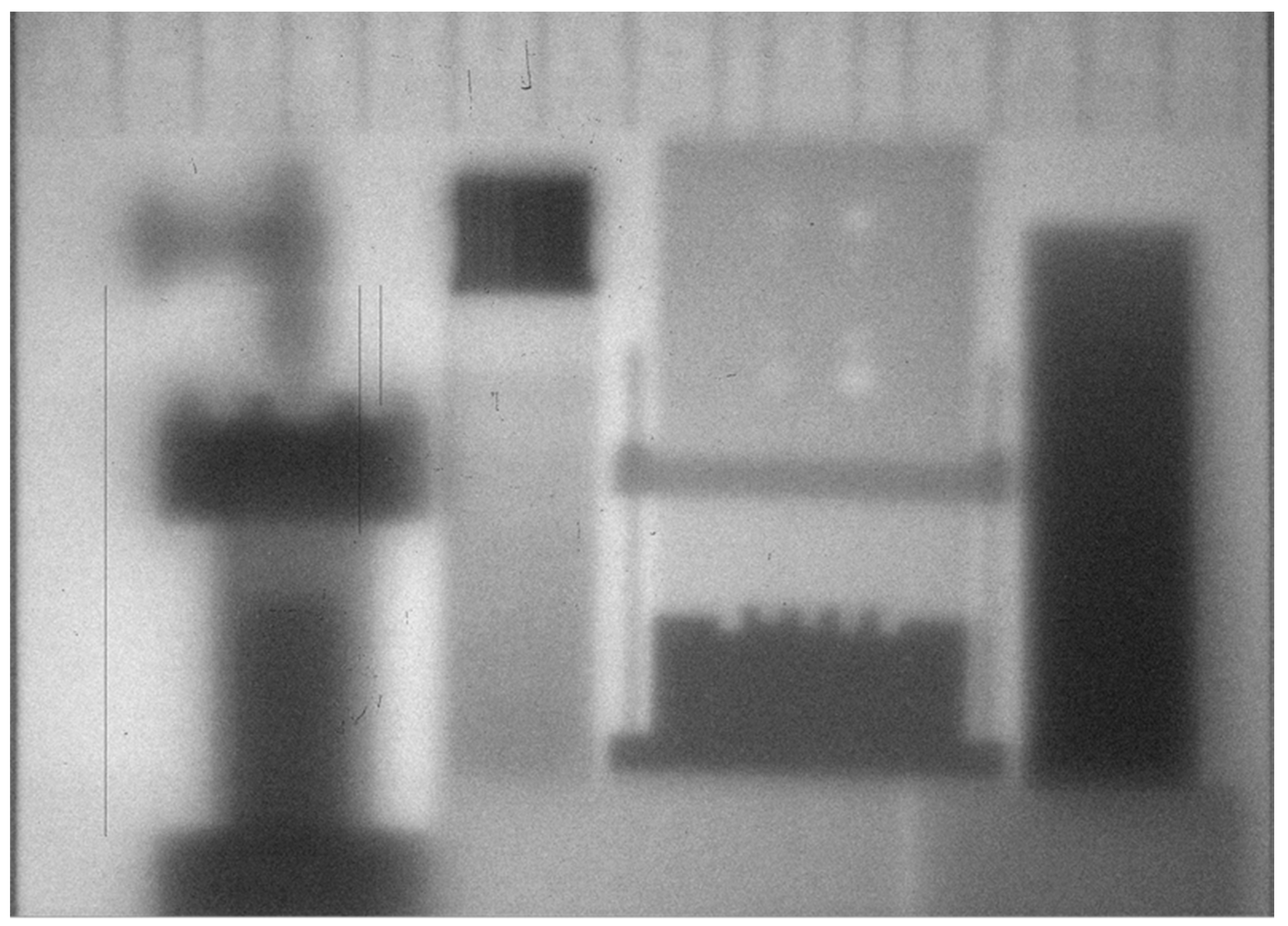
Figure 1. Neutron radiograph taken with a single laser-driven pulse at the TRIDENT laser at LANL (after [34]). The radiation penetrated a thick aluminum chamber window before reaching the objects and detector. The detector was an a-Si flat panel with a polypropylene plus ZnS:Cu neutron converter/scintillator. Objects from left to right include, a stainless steel and brass vacuum valve, a Ta and polyethylene line pair gauge sitting on top of a polyethylene step wedge, a steel, aluminum and polyethylene phantom and a tungsten wedge. The left side objects show greater blur due to the angle of neutron emission from the source.
Jimaging 04 00045 g001
Figure 2. Overview of the LANSCE facility (after [32]). The imaging beamlines discussed here are flight paths 5 and 11 off of Target 1 in ER1 and 60R off of Target 4 at the Weapons Neutron Research facility (WNR), all shown in red.
Jimaging 04 00045 g002
Figure 3. The neutron energy spectra for 1FP-05 at 8 m (black), 1FP-05 at 58 m (green) and 1FP-11 at 20 m (blue) at the Lujan Center and the 4FP-60R flux at 20 m at the WNR facility (red). The spectra were calculated and vetted with measurements for a proton beam current on Target 1 of 100 μA for the Lujan Center [37] and 4.0 μA at Target 4. (See text for details.).
Jimaging 04 00045 g003
Figure 4. Flight Path 05 Schematic. Beyond the first 10 m station, there is an evacuated pipe and some large diameter polyethylene shielding leading to the 60 m station.
Jimaging 04 00045 g004
Figure 5. James Hunter standing at the bottom of the “Silo”, the 60 m experimental station on 1FP-05. The neutron beam enters from the right. A flat panel imaging set up is at center, partially obscured by the spiral staircase. This station is located about 9 m underground.
Jimaging 04 00045 g005
Figure 6. Sample data collected with the 55 photomultiplier tube liquid scintillator detector at the 60 m station of flight-path 5. The large chart shows the entire 50 ms neutron pulse of the 20 Hz LANSCE Target 1. The area marked in blue is shown magnified in the left inset and the data shown in red in the left inset are displayed magnified in the right inset to illustrate the high energy resolution and large energy range available with this detector. Complementary imaging and tomography results are obtained from the MCP detector, with chemical characterization using neutron absorption resonances at higher energies obtained from the liquid scintillator detector.
Jimaging 04 00045 g006
Figure 7. Examples of the transmission data analysis using the SAMMY code for two fuel samples with enrichment levels of 0.2% (a) and 8.8% 235U (b).The difference curve between fit and experimental data is shown below.
Jimaging 04 00045 g007
Figure 8. Neutron computed tomography (CT) of UN/U3Si5 and U3Si5 fuel pellets with different enrichment levels. While the thermal neutron tomography (a), as available at a reactor, does not distinguish the differences in enrichment levels of the middle and lower pellet (8.84% and 0.2% enrichment, respectively), the reconstruction of 235U (b) and 238U (c) densities clearly provides this information.
Jimaging 04 00045 g008
Figure 9. Photograph of five 5 mm long, 4.6 mm diameter dUO2 mock-up fuel pellets in steel cladding (a), as well as 800 MeV proton radiography (b) [54], 450 keV X-ray radiography (c) [54], thermal neutron radiography (d), as well as radiographs at neutron absorption resonance energies of 238U (e) and tungsten (f) [44]. The sample orientation is not identical for each modality.
Jimaging 04 00045 g009
Figure 10. Thermal neutron (a) and hard X-ray CT scans (b) of a 62.3 million year old Tetraclaenodon puercensis. The surface (left in each part) and internal reconstructions (right) show the differences the two modalities provide.
Jimaging 04 00045 g010
Figure 11. Thermal neutron radiograph (a), epithermal neutron radiograph at the 18.6 eV W resonance (b) and CT reconstruction (c) of the central portion of an additively manufactured disk-shaped W test object. The thickness of the various areas is clearly visible including the LANL logo. In addition, gating on a W resonance (b) changes the contrast, making the non-W inclusions around the logo less visible.
Jimaging 04 00045 g011
Figure 12. A photograph of a juniper branch in the combined neutron radiography-and NMR set-up on 1FP-05 60 m station (a). Neutron radiographs of the branch (b) and time series of the neutron and NMR signal intensity during a D2O labeling and watering experiment on this juniper branch using an a-Si flat panel with GadOx scintillator screen (c). See text for details.
Jimaging 04 00045 g012
Figure 13. Neutron tomography of an intact pine root (a), vertical cross section showing bands of high (light) and low (dark) water content of the same root (b) imaged through soil and neutron radiograph of grass roots through soil (c).
Jimaging 04 00045 g013
Figure 14. X-ray (6 MeV) CT (a) and thermal neutron CT slices (b,c) taken at the 1FP-05 60 m station of a Mac mini (d). The X-ray image has higher resolution but does not reveal features seen well in the neutron images. A second thermal neutron slice in a different vertical plane shows other parts on the motherboard of the Mac Minicomputer. The labels seen on the front face of the Mac min (below the CD slot, (d) in the photograph are visible in the CT scan (e). The circular streaks are artifacts of the image reconstruction.
Jimaging 04 00045 g014
Figure 15. (a) A Perkin-Elmer 40 cm × 40 cm a-Si flat panel detector, model 1621, is shown located at 21 m from the Target 4 neutron production target in the inner shielding on the 4FP-60R flight path. Rotation and translation stages with an object are located in front of the flat panel; (b) A CCD camera (not visible) lens, mirror, plastic scintillator TOF-gated imaging setup with Cu step wedge at right.
Jimaging 04 00045 g015
Figure 16. High-energy neutron CT scan of a heavy tungsten-encased ceramic cathode assembly—cathode is shown in front of flat panel in Figure 15a. Cracks in the ceramic are difficult to impossible to image with X-rays. Slices in three different planes show (A) ceramic with cracks (B) spiral wound heating element near edge and center of ceramic (C) central support of heating element.
Jimaging 04 00045 g016
Figure 17. (a) A high-energy neutron radiograph of an aluminum alloy chili pepper, an iron pyrite (FeS, “fool’s gold”) double crystal and a pewter figurine of Kokopelli on a stopper inside a depleted uranium cylinder with 4 cm thick walls and dimensions 15.24 cm OD, 7.24 cm ID, 20.3 cm tall, weight 62 kg. (b) A CT slice through the center of the cylinder showing the pepper and iron pyrite crystals.
Jimaging 04 00045 g017
Figure 18. Photo of the 74.5 million year old skull of the tyrannosauroid dinosaur Bistahieversor sealeyi collected from northwestern New Mexico. A high-energy neutron radiograph taken in 4 sections of the left most portion of the skull is shown at far left. The fossil was also imaged with 6-MeV (Bremsstrahlung) X-rays at the Los Alamos Microtron facility. Good definition is seen in the images which may provide complimentary information to the X-ray images. Combining the multiple neutron images and reconstructing the CT scan is in progress.
Jimaging 04 00045 g018
Figure 19. (a) Images of a tantalum and polyethylene line pair gauge about 3 cm thick and 3 cm tall is on top of a polyethylene phantom with holes and partial holes; (b) A steel and polyethylene phantom with “teeth” and holes. The intensities at the location of the red horizontal line through the center is shown below the image at right.
Jimaging 04 00045 g019
Figure 20. Radiographs taken with (a) 6 MeV Bremsstrahlung source (Microtron) (b) TOF-gated 4FP-60R image for few MeV neutrons (c) higher energy neutrons. Notice the better penetration of the X-rays and higher energy neutrons through the plastic at the top. The X-ray set up is highly optimized while the neutron set up was a “first time” operation. The object is about 16 cm tall. The object is not at the same angular orientation in the different images.
Jimaging 04 00045 g020
Figure 21. Images from 4FP-60R for multiple neutron energy slices, showing the effects on contrast and resolution as the neutron energy bin width (8–12 vs. 9–11 MeV) and energy are changed from 2.5 to 60 MeV. The assembly shown is about 16 cm tall.
Jimaging 04 00045 g021
Figure 22. (a) photograph of Pb and aluminum wire object (b) cold neutron radiograph (c) phase contrast image using the propagation technique. The neutron images were taken with a MCP detector.
Jimaging 04 00045 g022
Figure 23. Cold neutron imaging of a hairline crack in an Al plate. (a) Photograph of cracked Al plate (b) cold neutron radiograph, 10 minutes exposure (c) phase contrast image using the propagation method, 10 minutes exposure. Bottom, (d,e) photos of the cracked plate between 20 cm of Al shielding (f) PCI of the plate inside 8 cm of Al shielding, 20 minutes exposure (g) PCI of the plate inside 20 cm of Al shielding, 25 minutes exposure. The neutron images were taken with a 6Li-ZnS:Ag phosphor on an aluminum backing coupled to an a-Si flat panel detector.
Jimaging 04 00045 g023
Table 1. Neutron-imaging beam line characteristics at LANSCE. Values shown are typical.
Flight Path/InstrumentEn RangeStation DistanceL/D (Minimum)Beam DimensionsIntegrated Flux 1 (n/cm2 s)
1FP-11 ASTERIX0.5–20 meV18–22 m10006 cm × 6 cm4.0 × 107
1FP-0525 meV–10 keV6–10 m1008 cm dia4.0 × 107
58–61 m725~100 cm dia6.0 × 105
4FP-60R0.6–400 MeV20–23 m300(H)/700(V)≤30 cm × 20 cm2.0 × 106
1 The ASTERIX flux value was measured for a proton current of 100 µA [37], with the flux of FP-05 at 9 m assumed to be equivalent to the measured FP4 flux, viewing the same moderator, from the same reference. The flux at 60 m for FP-05 was estimated from the 1/L2 ratios for 60 m and 9 m. We note that since the measurements described in [37], Target 1 was changed, adding to the inherent uncertainty of the absolute flux values which also depend on target age, proton beam focus and current. The 4FP-60R source is wider than tall giving different L/D ratios for horizontal and vertical resolution.
Table 2. Neutron-imaging detectors used at LANSCE.
InstrumentScintillator Screen/DetectorDetector Pixel PitchActive Area/Field of View
Storage Phosphor Image PlateLong-lived phosphor, Gd~70 µm20 cm × 25 cm to 40 cm × 40 cm
a-Si Flat PanelGadOx/ZnS:Cu100 or 200 µm400 mm × 400 mm
Cooled CCD cameraFast plastic, ZnS:Ag or Cu100 µm, typ.~200 mm dia.
iCCD cameraFast plastic~200 µm, typ.~200 mm dia.
Doped MCP10B/Gd-doped glass MCP55 µm, 22 µm with centroiding28 mm × 28 mm