Article

Design of an Energy-Efficient Pilot-Scale Pyrolysis Reactor Using Low-Cost Insulating Materials

by
José Alfredo Torres Tovar
1,
Hermelinda Servín-Campuzano
1,*,
Mauricio González-Avilés
1,
Hugo Sobral
2,
Francisco Javier Sánchez-Ruiz
3 and
Saúl Leonardo Hernández Trujillo
1
1
Programa de Doctorado en Ciencias para la Sostenibilidad e Interculturalidad, Universidad Intercultural Indígena de Michoacán, Carretera Pátzcuaro, Huecorio SN KM.3, Pátzcuaro 61614, Mexico
2
Instituto de Ciencias Aplicadas y Tecnología, Universidad Nacional Autónoma de México, Circuito Exterior S/N, Ciudad Universitaria, Mexico City 04510, Mexico
3
Facultad de Ingeniería Ambiental, Universidad Popular Autónoma del Estado de Puebla, 21 Sur 2316, Barrio de Santiago, Puebla 72410, Mexico
*
Author to whom correspondence should be addressed.
Recycling 2025, 10(6), 199; https://doi.org/10.3390/recycling10060199
Submission received: 13 September 2025 / Revised: 24 October 2025 / Accepted: 24 October 2025 / Published: 28 October 2025

Abstract

A pilot-scale reactor prototype was designed to produce hydrocarbons through the catalytic pyrolysis process of low-density polyethylene, thereby extending its life cycle and contributing to energy efficiency and sustainability. The reactor consists of a stainless-steel tank encased in a ceramic jacket with refractory cement and clay bricks. The tank, made of 304 stainless steel, ensures mechanical strength and efficient heat transfer to the reactor core. A spiral condenser was incorporated into a water tank to cool the vapors and recover the liquid oil. The insulating materials, ceramic, refractory cement and clay brick, demonstrated a high combined thermal resistance of 0.159 m2·K/W. Simulations and energy flow calculations demonstrated that heat is efficiently directed to the reactor core, reaching 350 °C with only 3000–3800 W, while the outside of the jacket remained close to 32 °C. These results confirm that the proposed design improves thermal efficiency and optimizes energy use for catalytic pyrolysis. The novelty of this design lies in its energy-efficient configuration, which can be replicated in rural regions worldwide due to the accessibility of its construction materials. This reactor was developed based on a smaller-scale model that previously yielded excellent results.

1. Introduction

Energy is fundamental for human needs, economic growth, and social well-being. However, global energy demand is projected to increase by nearly 50% between 2018 and 2050 [1], while around 80% of primary energy still comes from fossil fuels, which generate large amounts of CO2 emissions [2,3]. To address this challenge, research has focused on two main strategies: expanding renewable energy sources and improving efficiency through integrated systems that optimize energy use [4]. These approaches not only reduce emissions throughout the life cycle of energy systems but also align with regulatory policies on consumption and demand [5]. Achieving sustainable development requires a transition toward low-carbon models that foster economic growth, reduce inequalities, and protect the environment [6]. In this context, renewable sources such as solar, wind, and biomass play a key role [7,8].
Among emerging renewable technologies, catalytic pyrolysis of plastic waste offers a promising pathway to simultaneously address energy generation, emission reduction, and circular economy goals [9,10,11,12,13,14,15,16,17,18]. Plastic production has facilitated global packaging and transportation, yet poor recycling practices have turned plastics into one of the most pressing environmental threats, with global demand increasing by about 5% annually [17]. Currently, only around 10% of plastic waste is recycled, while the rest accumulates in landfills, rivers, and oceans, releasing toxic gases during incineration [19]. These challenges highlight the urgent need for innovative and sustainable recycling technologies that can contribute to the goals of the 2030 Agenda.
Pyrolysis represents a viable thermochemical route for converting plastic waste into valuable fuels while avoiding the toxic emissions associated with incineration [20,21,22]. In particular, catalytic pyrolysis using zeolite-based catalysts improves oil yield and quality at lower operating temperatures, producing high-energy bio-oil and gas [23,24,25,26,27]. Previous studies have reported yields up to 22.5% using catalysts, compared to 18% for thermal pyrolysis [28,29,30,31,32,33,34]. The process produces liquid hydrocarbon oil, non-condensable gas, and a solid residue. In previous work performed by our group, a laboratory-scale prototype demonstrated that this liquid fraction is composed of gasoline-like aromatic hydrocarbons, including benzene, toluene, and xylenes [35].
Scaling up this technology requires efficient reactor designs that ensure safety, thermal stability, and economic viability. Parameters such as heat transfer efficiency, condenser performance, and multilayer insulation play crucial roles in maximizing energy recovery and process sustainability [29,33,36]. While most existing designs remain at laboratory or small pilot scale, developing cost-effective semi-industrial reactors from locally available materials offers a practical solution, especially for rural contexts [35]. Such innovations support environmental sustainability and energy access objectives [36,37,38].
Various reactor configurations have been reported for plastic pyrolysis, including batch, semi-batch, fixed-bed, fluidized-bed, rotary kiln, and flow reactors. Batch and fixed-bed systems are simple and suitable for laboratory studies but often suffer from uneven heating and limited scalability. Fluidized-bed reactors provide uniform temperature distribution and continuous operation but require complex control systems and high construction costs. Rotary kilns can process larger feedstocks but entail higher energy consumption and mechanical complexity. Flow reactors, while efficient for gaseous or liquid feeds, are less adaptable for solid plastics [39,40,41].
Regarding construction materials, most reactors are built using stainless steel (grades 304 or 316) due to their high-temperature resistance, corrosion protection, and mechanical strength [13,14,15]. Some designs incorporate carbon steel or nickel-based alloys to reduce cost, while refractory linings and ceramics are applied to minimize heat losses [16]. However, these industrial materials increase fabrication cost and limit accessibility for decentralized applications.
The present work addresses these challenges by proposing a pilot-scale reactor constructed from low-cost and locally available materials, including refractory cement, ceramic, and red clay brick for insulation, combined with a stainless-steel core for mechanical stability. This configuration balances energy efficiency, durability, and affordability, making it suitable for implementation in rural or low-resource regions [18,19,42].
Overall, this study helps bridge the gap between laboratory-scale systems and real-world applications, demonstrating that high thermal efficiency can be achieved through simple, replicable, and affordable reactor designs. The proposed reactor emphasizes heat retention through multilayer insulation, reduced energy consumption, and scalability for decentralized contexts. Unlike complex microwave-assisted or continuous-flow systems, this design highlights simplicity, energy efficiency, and adaptability. Its innovation lies in demonstrating that high energy performance can be achieved using low-cost, locally available materials, enabling decentralized implementation of catalytic pyrolysis in regions lacking industrial infrastructure.

2. Results

2.1. Prototype Description

The prototype comprises a reactor consisting of a steel tank encased in two layers of high-temperature ceramic and refractory cement, forming the external insulation (see Figure 1). The reactor lid is connected via tubing to a condenser, which consists of a water reservoir and a coiled tube and is further linked to a liquid–gas separator.
This study focuses on the thermal efficiency and mechanical design of the reactor’s insulated vessel. For clarity in the thermal model, essential components such as the feed system and external heat source have been considered but are not detailed in the figures. The design allows loading through a sealed flange on the lid and is intended to be heated by an integrated combustion chamber located below the vessel. This chamber is specifically designed to be fueled by high-calorific briquettes developed from local biomass waste, in line with the project’s goal of creating a low-cost and sustainable system.
During operation, plastic waste is introduced into the steel tank of the reactor. Upon heating, thermal energy is transferred to the plastic, inducing its thermochemical decomposition and phase transition from solid to liquid and gaseous products. The resulting vapors are conveyed through the tubing to the condenser, where the coil, immersed in water, promotes cooling and condensation. This process converts the gases into liquid hydrocarbons, known as pyrolysis oil.

2.2. Thermal Properties of Materials

Finding suitable alternative resources is essential to reduce traditional energy consumption and promote sustainable development. Energy efficiency is a key sustainability goal, and thermal insulation materials have been developed to meet this objective by combining low thermal conductivity, low density, and high thermal resistance [43]. Energy saving is a strategic objective that contributes to environmental protection and the preservation of natural resources. Thermal insulation is therefore an increasingly important tool for conserving energy. Table 1 and Table 2 present the thermal properties of traditional insulation materials as reported under standardized testing [44].
To analyze energy efficiency in the reactor design, two key aspects were considered: thermal conductivity and thermal resistance. These properties were used to design the reactor jacket to minimize heat loss by conduction and convection.
Thermal resistance is defined as the ratio of the temperature difference between the two faces of a material to the rate of heat flow per unit area. Thermal resistance determines the heat insulation property of a material [45]. The higher the thermal resistance, the lower is the heat loss. The thermal resistance, R ( m 2 · K / W ), is connected with the thermal conductivity, λ ( W / m · K ), and the thickness, τ (m), as follows:
R = τ λ
for example, the ceramic layer has
R = 0.025   ( m ) / 1.4   ( W / m · K ) 0.018   m 2 · K / W
As expected, the red clay brick, exhibits the highest R value, followed by the ceramics and refractory cement, while steel shows the lowest. The combined thermal resistance of the insulating layers is 0.1593 m2·K/W, which is over 1625 times higher than that of the steel layer alone (0.000098 m2·K/W). This confirms that the insulation layers substantially enhance heat retention and energy efficiency in the reactor design.

2.3. Heat Transfer and Thermal Efficiency

Convective heat transfer is one of the three fundamental mechanisms of heat exchange between a solid surface and a surrounding fluid, such as air. It is described by Newton’s law of cooling, which relates the heat transfer rate to the surface area, the convective heat transfer coefficient, and the temperature difference between the surface and the fluid. The heat transfer in the reactor wall was analyzed considering convection and conduction layers, following Newton’s cooling law [46,47]. In the context of the jacketed reactor, convective heat flow plays a critical role in determining how heat is dissipated from the reactor surface to the surrounding environment. Accurate estimation of this heat transfer rate is essential to assess the thermal efficiency of the reactor, guide the design of the insulation system, and ensure that the desired internal temperatures are achieved while minimizing energy losses. At a steady state and under perfectly mixing conditions, the heat transfer rate can be evaluated as [48]
Q H = h T   A H   ( T s T b )
where h T   ,   A H   ,   T s ,   a n d   T b are the heat transfer coefficient, Q H is the heat transfer rate (W), h T is the heat transfer coefficient ( W / m 2 · K ) with a value for air of h T   =   15   W / m 2 K ; A H is heat-transfer area ( m 2 ), A H   = 0.78   m 2 ; T s is the surface temperature of the heating (°C), T s = 350   ° C and T b is the fluid temperature, T b = 25 °C. Thus, Q H   3802   W .
This calculation provides an estimate of the power needed to reach 350 °C, which was taken as the base parameter in the simulation.
The simulation results indicate that thermal energy is concentrated toward the center of the tank, while the multilayer insulation effectively minimizes heat loss to the surroundings. As shown in Figure 2, the internal temperature of the tank reaches 350 °C, whereas the external jacket surface remains below 32 °C, confirming the efficiency of the insulation system.
The convection coefficient ( h T ) depends on factors such as temperature, wind speed, and surface orientation. For upward and horizontal heat flow, h T can reach ~9.26 W/m2·K for absorbent surfaces and ~4.31 W/m2·K for reflective ones. Under outdoor natural convection, typically ranges between 5 and 25 W/m2·K. Conversely, experimental studies report that for downward-facing surfaces h T ranges between 0.4 and 2.05 W/m2·K, while in closed spaces it is generally lower due to restricted air circulation [35,49].
Table 3 summarizes the applied conditions and the calculated values for the maximum and minimum internal temperatures of the tank, as well as its surface temperature.
During the pyrolysis process, the working pressure inside the tank is assumed to be approximately 1 bar. However, the prototype has been designed to withstand higher pressures of several bars. To ensure safe operation, a pressure gauge has been installed for continuous monitoring, and a relief valve has been incorporated to mitigate the risk of overpressure due to potential blockages in the outlet pipe. The simulation model was conceptually validated against our previous experimental work on a smaller-scale prototype. That published study demonstrated the feasibility of the thermal concept and the effectiveness of the operating parameters. Therefore, the present study uses those parameters as a reference to model the scalability and thermal performance of the pilot-scale design, which is a critical step prior to construction.

3. Discussion

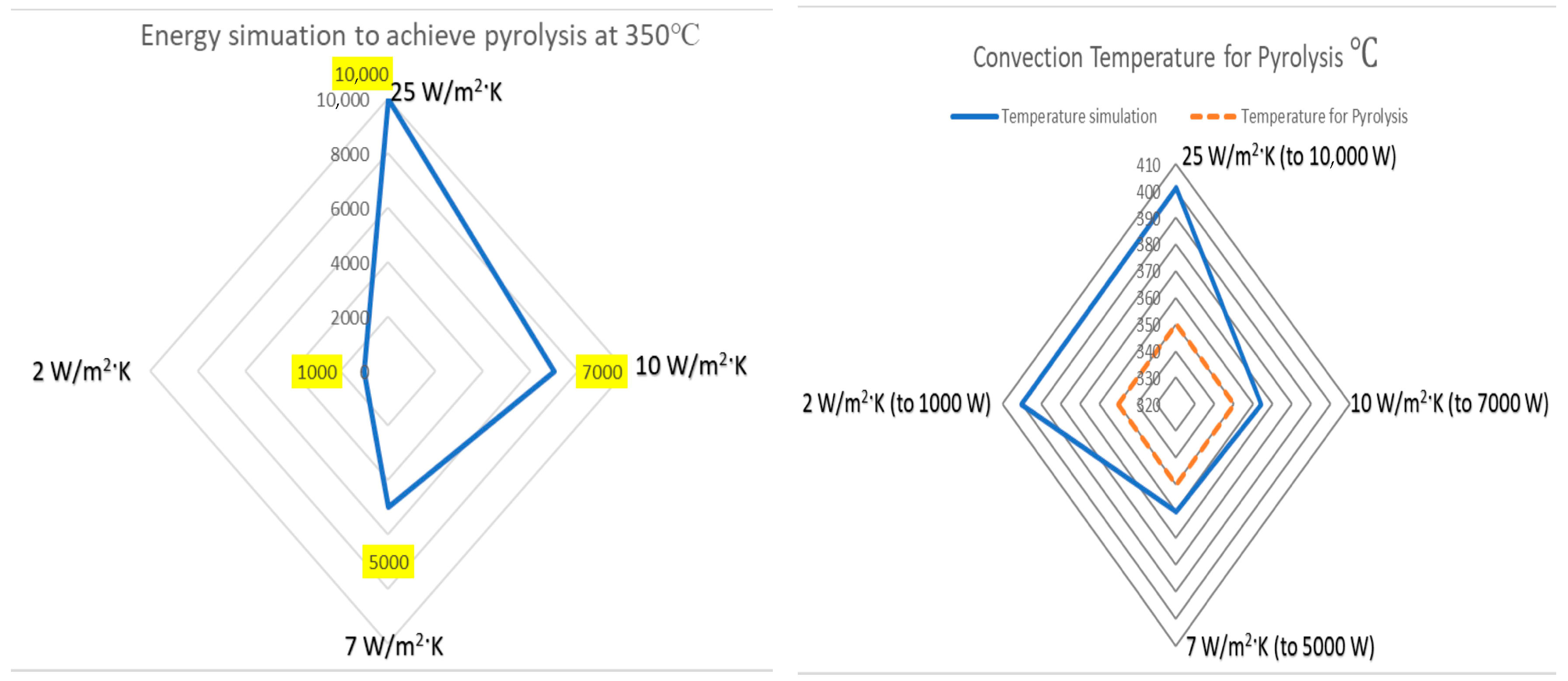
The steady-state simulations highlight the decisive role of convection in determining the energy demand to achieve pyrolysis conditions. Under adiabatic conditions, where all applied energy is retained by the reactor, variations in the convection coefficient strongly influence the heating power required to reach 350 °C. In free-air conditions (25 W/m2·K), pyrolysis was only achieved at 10,000 W, evidencing extensive heat loss due to natural convection. When the convection coefficient was reduced to 10 W/m2·K, the required power decreased to 7000 W, while a further reduction to 7 W/m2·K lowered the demand to 5000 W. The most pronounced effect was observed at 2 W/m2·K, which approximates a near-adiabatic condition in the insulated reactor jacket, where pyrolysis was reached with only 1000 W. These results confirm that multilayer insulation effectively minimizes heat loss by reducing direct contact with ambient air.
Overall, the findings underscore the decisive role of convection control in pyrolysis reactor design. Open-air configurations demand much higher energy input, whereas insulation and reduced air movement drastically reduce the required heating power, enhancing both energy efficiency and process sustainability. Although all four scenarios surpassed the pyrolysis threshold, the energy demand varied by an order of magnitude, from 10,000 W in open-air conditions to just 1000 W under near-adiabatic conditions. Minimizing convective heat transfer is therefore essential to achieve substantial energy savings in thermal processes.
The proposed prototype design directly addresses these challenges. The insulating jacket was conceived to minimize heat losses by limiting direct contact with ambient air, while the selected materials are suitable for high-temperature operation. Refractory ceramic, with thermal conductivity between 1.4 and 3.0   W / m · K , withstands 1650–2500 °C, while refractory cement, with conductivity values ranging from 1.2 to 4.0   W / m · K , operates up to 2200 °C. Red brick, composed primarily of clay, provides additional thermal resistance. For the reactor tank, 304 2B stainless steel was selected due to its favorable thermal conductivity ( 16.2   W / m · K ), which promotes efficient heat transfer toward the reactor core and supports efficient pyrolysis. Figure 3, summarizes the influence of convection on reactor performance and highlights how insulation strategies translate into lower energy demand.
These results not only demonstrate the thermal efficiency of the proposed design but also provide a scalable framework for energy optimization in larger systems. The same insulation principles can be applied to semi-industrial pyrolysis units to reduce operational costs and energy consumption. The proposed design methodology is based on accepted principles, including ASME Section VIII codes for pressure vessels and standard heat transfer equations. Thus, although the specific values of the calculations correspond to an 800-L pilot reactor, the methodology used can be adapted to the design of larger-scale reactors by simply adjusting the input parameters (dimensions, materials, and operating conditions).

4. Materials and Methods

4.1. Reactor Tank Material

For reactor design, stainless steel is a good choice due to its mechanical, thermal, and oxidation-resistance characteristics. Stainless Steel 304-2B is an austenitic stainless-steel alloy with a surface finish known as 2B, which refers to a cold-rolled surface that is then treated with a passivation treatment. Stainless steel 304 is widely used due to its good corrosion resistance and its versatility in various industrial applications [49].
The allowable stress or resistance limit of 304-2B stainless steel may vary depending on the norm or standard used, as well as the specific load and temperature conditions. Thus, it is important to consult the applicable technical specifications or standards for accurate allowable stress data. For reference, the typical yield stress of 304 stainless steel is in the range of 205 to 275 MPa. This stress must be taken into account in the design due to the pressures to which the material will be subjected, and the tensile strength, which is generally between 515 and 690 MPa. These values may vary depending on the condition of the material and the heat treatments applied [45,50]. The thermal conductivity of 304-2B stainless steel is 16.2   W / m · K , which is relevant for heat transfer in the pyrolysis reactor and its simulation.
Three thicknesses and their compositions are considered: 1.5, 2.0 and 3.0 mm as shown in Table 4.

4.2. Reactor Tank Design

The design of vessels operating under internal pressure is based on NRF-028-PEMEX-2004 [16], Chapter 8, paragraph 8.1.2, which refers to the UG part of Section VIII, Division 1. This part of the ASME Code [15], provides formulas and parameters that must be considered for the design. These variables are mainly pressure ( P ) and design temperature (T). For circumferential stresses, as taken from ASME Section VIII, Division 1, construction of internal pressure vessels, the following expression is used [52,53]:
P   = S E τ r   + 0.6 τ
τ = P   R S   E 0.6 P
where τ is the minimum wall thickness (mm), P is the design pressure Psi (MPa), r is the internal radius in ( m m ) , S is the maximum stress of the material at the desired temperature Psi (MPa), E is the material joint efficiency.
For an 800-L tank made of 14-gauge 304-2B stainless steel plate 1.92   mm thick, the following values were used: τ   = 1.92   m m , r   = 500   m m , S   =   250   M P a stainless steel stress, E is 1 (ASME Section VIII division 1).
The design pressure was calculated as: P = ( 250   M P a ) ( 1 ) ( 1.92   m m ) 500   m m + 0.6 ( 1.92   m m ) .
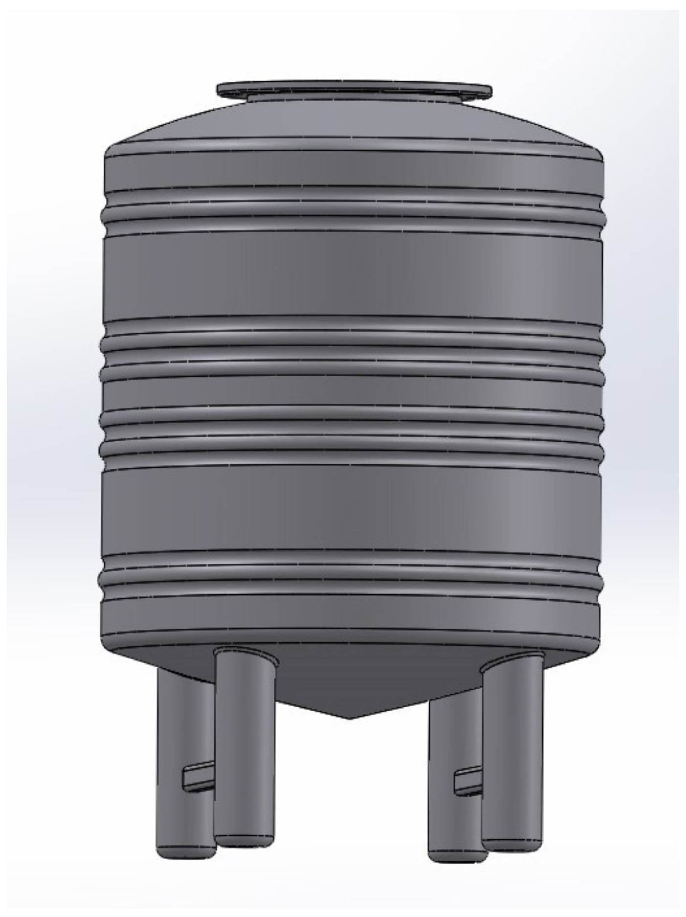
The calculations indicate that P has a value of 0.958   MPa . Considering a 50% safety factor, the working pressure is P ≈ 0.48 MPa. Figure 4 shows the tank design with the characteristics specified above.
The volume of the tank is 800   L ( 0.8   m 3 ) , and the density of LDPE is 920   k g / m 3 . The density of LDPE (0.92 g/cm3) was taken from ASTM D792-13 [54]. The maximum mass of plastic the tank can hold is calculated as
m = v p
where m is the mass (kg), v is the volume ( m 3 ), p is the density ( k g / m 3 ).
Thus, m = ( 0.8   m 3 )( 920   k g / m 3 ) = 736   k g .
The feed load in batch pyrolysis reactors is commonly expressed as a fill ratio (per-centage of reactor volume occupied by feedstock). This has a significant impact on heat transfer, particularly in indirect heating designs such as the one proposed. Batch configurations can suffer from poor heat transfer characteristics when processing low-conductivity materials such as plastics. To ensure more uniform heating, a low fill ratio is preferable. Therefore, an operating fill ratio range of 10% to 15% has been selected for this 800 L pilot reactor. This corresponds to a workload between 73.6 kg (at 10%) and 110.4 kg (at 15%) of LDPE per batch [55,56].
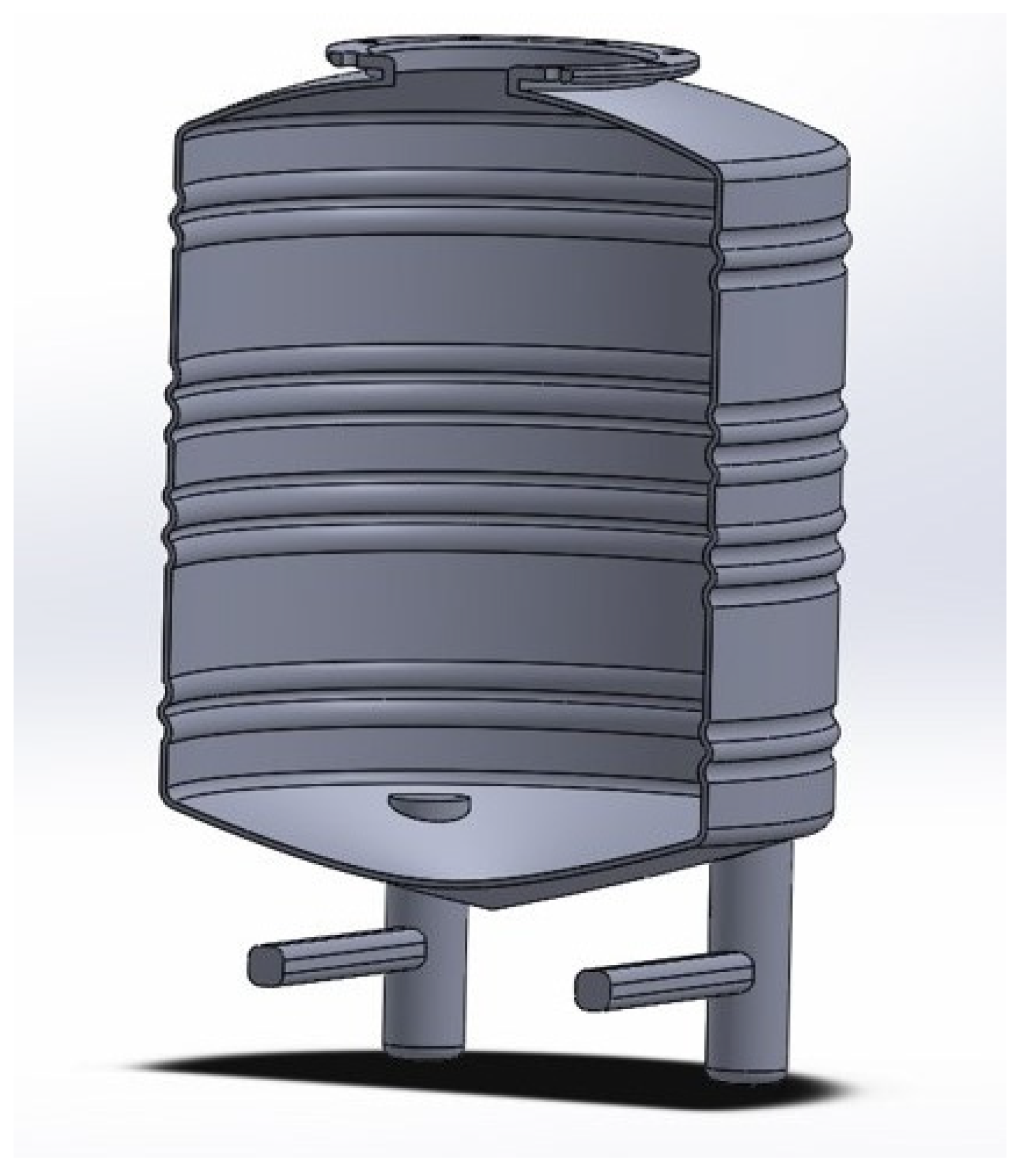
Figure 5 shows a cross-section of the tank and its interior volume view for containing plastic during the catalytic pyrolysis process.
The design of the cover is flat to adapt to the tank flange, aiming to achieve a total seal and prevent gas escape. The connection pipe to the condenser and the pump was also included to allow vacuum creation, and the cover is also made of stainless steel, as shown in Figure 6.
A flanged joint will be placed on both the flat cover and the tank. Its design follows the ASME Section VIII code:
τ   = D   c p S E
where τ is the minimum flange thickness (mm), p is the design pressure (0.48 MPa), D is the flange diameter (550 mm), S is the maximum stress of the material (250 MPa), E is the material joint efficiency (1), and c is the factor for the type of cover joint (bolted plates: 0.162).
The minimum flange thickness for the cover and tank is t = 10 mm + 10% safety = 11 mm. The flange, designed to fit the tank opening, is shown in Figure 7.
To calculate the force on each screw, the cover area (1963 cm2) is multiplied by the working pressure obtained from Equation (1). This gives a total force of 94   k N . Since the design uses eight screws, the load per screw is 11.75   k N . Such a load can be safely supported by a half-inch diameter screw or its metric equivalent [57].

4.3. Reactor Jacket

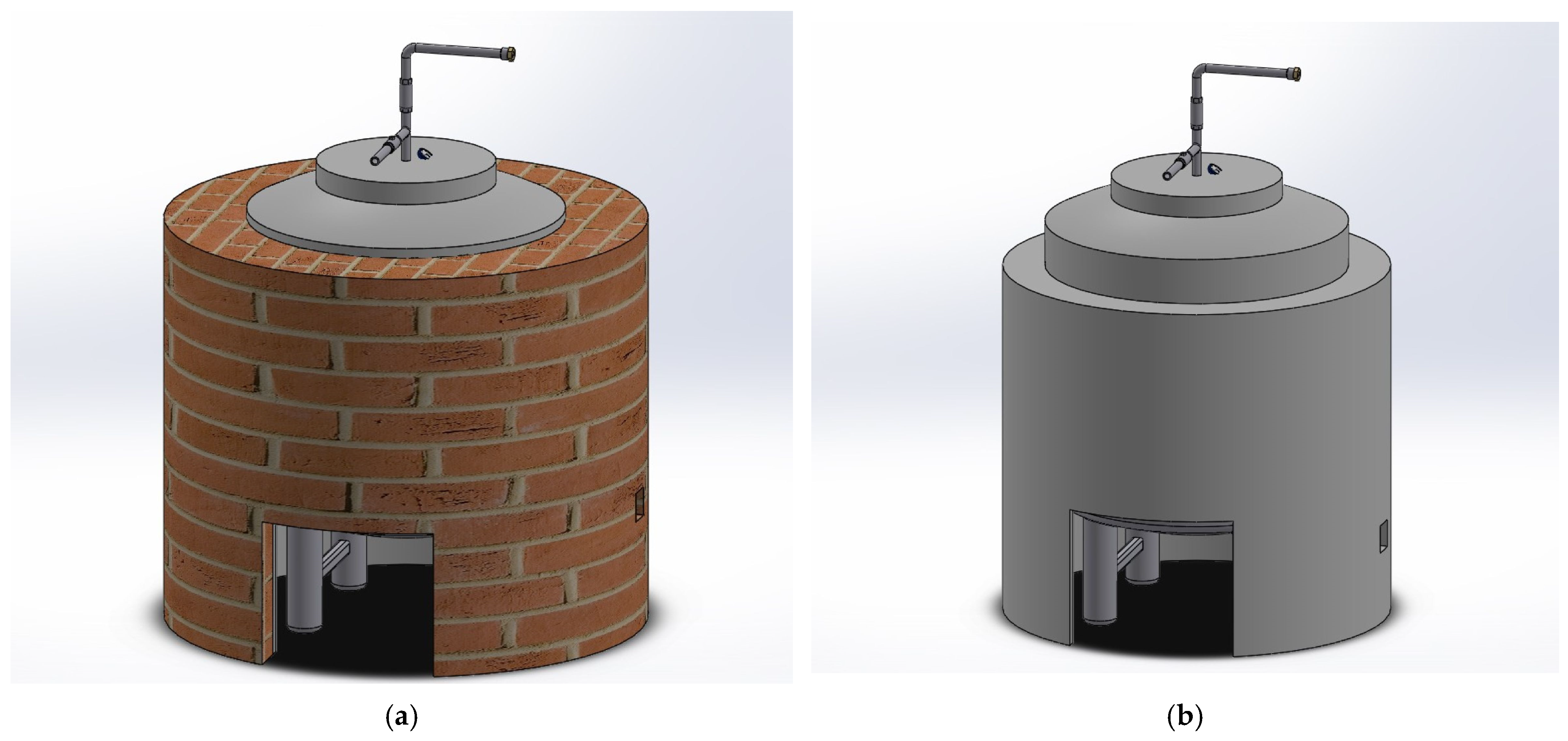
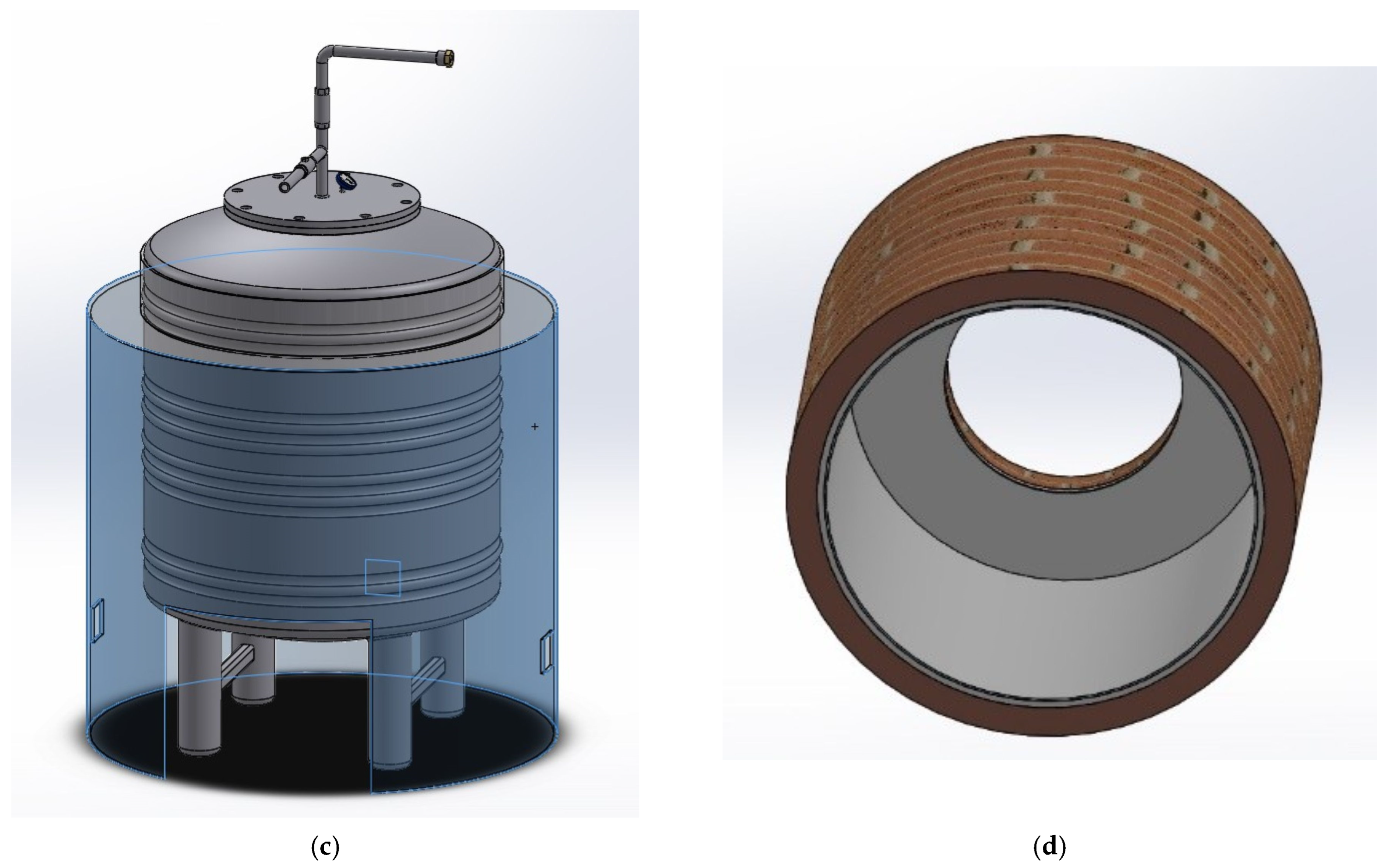
The objective of the jacket design is to improve energy efficiency by minimizing heat loss through convection and concentrating it within the reactor tank. The proposal follows an ecological approach by reducing energy consumption and involves the construction of a jacket that covers the tank with three thermally insulating layers, selected based on their material characteristics. The first layer is a high-alumina, hydraulic-setting castable refractory cement, suitable for applications exceeding 1000 °C. The second layer consists of a high-purity alumina-silica ceramic fiber blanket, a lightweight insulating material with a service temperature rating of up to 1200 °C. The third layer is made of red clay brick wall, as shown in Figure 8. The materials chosen provide a significant safety margin against possible temperature overshoots and ensure the long-term structural durability of the jacket over many operating cycles.

4.4. Simulation Parameters

A thermal simulation of the prototype was performed in SolidWorks 2011 SP05 [58] using the following parameters: the reactor tank, constructed of 14-gauge 304 stainless steel with a thermal conductivity of 16.2   W / m · K . The jacket surrounding the tank consists of three layers: (i) refractory cement ( 1.2   W / m · K ), (ii) ceramic insulation ( 1.4   W / m · K ) , and (iii) red clay brick ( 0.9   W / m · K ).
A heating power input of 3000 W was applied. Furthermore, a parametric analysis was conducted by varying the heating power and setting different convection coefficients (25, 10, 7, and 2 W/m2·K) to assess the reactor’s performance under different operational conditions. A constant emissivity of 0.3 was used for the external surfaces. The analysis focused exclusively on heat transfer, assuming external atmospheric pressure conditions, and did not evaluate the mechanical stress related to the reactor’s internal design pressure of 0.48 MPa.

5. Conclusions

This study presents the design and simulation of a pilot-scale catalytic pyrolysis reactor for the recycling of low-density polyethylene (LDPE). The reactor achieved an internal temperature of 350 °C using only 3000–3800 W, while the external surface temperature remained below 32 °C, confirming the high thermal efficiency of the multilayer insulation system. The combined thermal resistance of the multilayer insulation system was 0.1593 m2·K/W, over 1600 times higher than that of the stainless-steel wall alone, significantly reducing heat losses.
The simulations showed that reducing the convection coefficient from 25 W/m2·K (open air) to 2 W/m2·K (insulated condition) decreased the power demand from 10,000 W to only 1000 W, representing an order of magnitude improvement in energy efficiency. These results validate the concept of using low-cost, readily available materials such as ceramic, refractory cement, and clay bricks to achieve high performance.
The novelty of this design lies in its simplicity, replicability, and accessibility: it can be built and installed in rural or low-resource areas without the need for complex equipment. The prototype was scaled up from a smaller reactor that previously demonstrated excellent experimental results, confirming the feasibility of the approach.
Future work will include experimental validation of the pilot reactor and quantitative comparison between simulated and measured data. Furthermore, a detailed optimization study will be carried out to analyze the cost–benefit ratio of the insulation layer thicknesses, refining the thermal model and confirming its scalability.

Author Contributions

J.A.T.T. wrote the first draft of the manuscript which was then refined by H.S.-C. and H.S., Conceptualization, H.S.-C. and H.S.; methodology, H.S.-C. and M.G.-A.; software, J.A.T.T. and S.L.H.T.; validation, M.G.-A., F.J.S.-R. and H.S.; formal analysis, H.S.-C.; investigation, H.S.-C. and F.J.S.-R.; resources, J.A.T.T., M.G.-A. and H.S.-C.; data curation, H.S. and H.S.-C.; writing—review and editing, H.S.-C. and H.S.; supervision, H.S.-C.; project administration, H.S.-C.; funding acquisition, H.S.-C., M.G.-A. and J.A.T.T. All authors have read and agreed to the published version of the manuscript.

Funding

This research received no external funding.

Data Availability Statement

Dataset available on request from the author.

Acknowledgments

José Alfredo Torres Tovar: CVU 1063404 received national fellowship (traditional 2022-2) from SECIHTI-México. We gratefully acknowledge Corporate Industrial Uruapan (CIU) for their contribution to the project and for providing the SolidWorks 2011 SP05 software used in the design and simulations.

Conflicts of Interest

The authors declare no conflicts of interest.

References

  1. Halkos, G.E.; Gkampoura, E.-C. Reviewing usage, potentials, and limitations of renewable energy sources. Energies 2020, 13, 2906. [Google Scholar] [CrossRef]
  2. Harjanne, A.; Korhonen, J.M. Abandoning the concept of renewable energy. Energy Policy 2019, 127, 330–340. [Google Scholar] [CrossRef]
  3. Taghizad-Tavana, K.; Alizadeh, A.A.; Ghanbari-Ghalehjoughi, M.; Nojavan, S. A comprehensive review of electric vehicles in energy systems: Integration with renewable energy sources, charging levels, different types, and standards. Energies 2023, 16, 630. [Google Scholar] [CrossRef]
  4. Dinh, H.T.; Yun, J.; Kim, D.M.; Lee, K.-H.; Kim, D. A home energy management system with renewable energy and energy storage utilizing main grid and electricity selling. IEEE Access 2020, 8, 49436–49450. [Google Scholar] [CrossRef]
  5. Piotr, W.; Mariusz, N. Assessment of the possibility of using various types of renewable energy sources installations in single-family buildings as part of saving final energy consumption in Polish conditions. Energies 2022, 15, 1329. [Google Scholar] [CrossRef]
  6. Dzwigol, H.; Kwilinski, A.; Lyulyov, O.; Pimonenko, T. The role of environmental regulations, renewable energy, and energy efficiency in finding the path to green economic growth. Energies 2023, 16, 3090. [Google Scholar] [CrossRef]
  7. Sebestyén, V. Renewable and Sustainable Energy Reviews: Environmental impact networks of renewable energy power plants. Renew. Sustain. Energy Rev. 2021, 151, 111626. [Google Scholar] [CrossRef]
  8. Qazi, A.; Hussain, F.; Rahim, N.A.; Hardaker, G.; Alghazzawi, D.; Shaban, K.; Haruna, K. Towards sustainable energy: A systematic review of renewable energy sources, technologies, and public opinions. IEEE Access 2019, 7, 63837–63851. [Google Scholar] [CrossRef]
  9. Harusasni, M.M.; Sapuan, S.M.; Khalina, A.; Ilyas, R.A.; Hazrol, M.D. Review on green technology pyrolysis for plastic waste. In Proceedings of the 7th Postgraduate Seminar on Natural Fibre Reinforced Polymer Composites, Serdang, Selangor, Malaysia, 17 November 2020; pp. 50–53. [Google Scholar]
  10. Papari, S.; Hawboldt, K.; Fransham, P. Study of selective condensation for woody biomass pyrolysis oil vapours. Fuel 2019, 245, 233–239. [Google Scholar] [CrossRef]
  11. Kabeyi, M.J.B.; Olanrewaju, O.A. Review and Design Overview of Plastic Waste-to-Pyrolysis Oil Conversion with Implications on the Energy Transition. J. Energy 2023, 2023, 1821129. [Google Scholar] [CrossRef]
  12. Piotr, M.P. Experimental and theoretical study on the internal convective and radiative heat transfer coefficients for a vertical wall in a residential building. Energies 2021, 14, 5953. [Google Scholar] [CrossRef]
  13. Wang, Y.; Liu, M.; Zhang, P.; Su, C.; Zhang, P.; Chi, B.; Xu, K.; Ma, F. Wear properties of self-lubricating Cr x S y/Ni coatings on 304 stainless steel by pre-placed laser cladding. Surf. Eng. 2021, 37, 1541–1549. [Google Scholar] [CrossRef]
  14. Panmongkol, P.; Phung-On, I. Effect of backing gas mixtures on corrosion properties of stainless steel grade 304 weld metal by autogenous GTAW. J. Mater. Res. Technol. 2021, 11, 2238–7854. [Google Scholar] [CrossRef]
  15. American Society of Mechanical Engineers. VIII, Division 1, Rules for Construction of Pressure Vessels; American Society of Mechanical Engineers: New York, NY, USA, 2013. [Google Scholar]
  16. PEMEX. Diseño y Construccion de Recipientes a Precion; NRF-028.PEMEX-2010; PEMEX: Mexico City, Mexico, 2010. [Google Scholar]
  17. Damián Valerio, R.S. Estudio del Estado Tensional en Uniones Atornilladas Mediante Solidworks. Bachelor’s Thesis, Universidad Politecnica de Cartagena, Cartagena, Spain, March 2018. [Google Scholar]
  18. Le Duong, H.A.; Zolt, P. An overview of factors influencing thermal conductivity of building insulation materials. J. Build. Eng. 2001, 1, 102604. [Google Scholar]
  19. Basim, A.-J.; Mourad, A.-H.; Hittini, W.; Hassan, M.; Hameedi, S. Traditional, state-of-the-art and renewable thermal building insulation materials: An overview. Constr. Build. Mater. 2019, 214, 709–735. [Google Scholar]
  20. Michalak, P. xperimental Study on Heat Transfer Coefficients in an Office Room with a Radiant Ceiling During Low Heating Loads. Energies 2025, 18, 1591. [Google Scholar] [CrossRef]
  21. Moriarty, P.; Honnery, D. Energy accounting for a renewable energy future. Energies 2019, 12, 4280. [Google Scholar] [CrossRef]
  22. Reid, W.V.; Ali, M.K.; Field, C.B. The future of bioenergy. Glob. Chang Biol. 2020, 26, 274–286. [Google Scholar] [CrossRef] [PubMed]
  23. Mandley, S.; Wicke, B.; Junginger, H.; van Vuuren, D.; Daioglou, V. Integrated assessment of the role of bioenergy within the EU energy transition targets to 2050. GCB Bioenergy 2022, 14, 157–172. [Google Scholar] [CrossRef]
  24. Nanda, S.; Berruti, F. A technical review of bioenergy and resource recovery from municipal solid waste. J. Hazard. Mater. 2021, 402, 123970. [Google Scholar] [CrossRef]
  25. Jonghun, L.; Yuchan, A.; Junghwan, K. Optimal sorting and recycling of plastic waste as a renewable energy resource considering economic feasibility and environmental pollution. Process Saf. Environ. Prot. 2023, 169, 695–696. [Google Scholar]
  26. Armenise, S.; SyieLuing, W.; Ramírez-Velásquez, J.M.; Launay, F.; Wuebben, D.; Ngadi, N.; Rams, J.; Muñoz, M. Plastic waste recycling via pyrolysis: A bibliometric survey and literature review. J. Anal. Appl. Pyrolysis 2021, 158, 105–265. [Google Scholar] [CrossRef]
  27. Vijayakurmar, A.; Sebastian, J. Pyrolysis process to produce fuel from diffent types of plastic a review. IOP Conf. Ser. Mater. Sci. Eng. 2018, 396, 012062. [Google Scholar] [CrossRef]
  28. Zhou, N.; Dai, L.; Lv, Y.; Li, H.; Deng, W.; Guo, F.; Ruan, R. Catalytic pyrolysis of plastic wastws in a continuous microwave assisted pyrolysis sistem for fuel production. Chem. Eng. J. 2021, 418, 129412. [Google Scholar] [CrossRef]
  29. Jha, K.K.; Kannan, T. Recicling of plastic waste into fuel by pyrolysis a review. Mater. Today Proc. 2021, 37, 3718–3720. [Google Scholar]
  30. Maqsood, T.; Dai, J.; Zhang, Y.; Guang, M.; Li, B. Pyrolysis of plastic species: A review of resorces and products. J. Anal. Appl. Pyrolysis 2021, 159, 105295. [Google Scholar] [CrossRef]
  31. Qureshi, M.S.; Oasmaa, A.; Pihkola, H.; Deviatkin, I. Pyrolysis of plastic waste: Opportunities and challenges. J. Anal. Appl. Pyrolysis 2020, 152, 104804. [Google Scholar] [CrossRef]
  32. Sharuddin, S.; Abnisa, F.; Daud, W.; Auroua, M. Pyrolysis of plastic waste for liquid fuel production as prospective energy resource. IOP Conf. Ser. Mater. Sci. Eng. 2018, 334, 012001. [Google Scholar] [CrossRef]
  33. Abdy, C.; Zhang, Y.; Wang, J.; Yang, Y.; Artamendi, I.; Allen, B. Pyrolysis of polyolefin plastic waste and potential applications in asphalt road construction. A technical review. Resour. Conserv. Recycl. 2022, 180, 106213. [Google Scholar] [CrossRef]
  34. Anuar Sharuddin, S.D.; Abnisa, F.; Wan Daud, W.M.A.; Aroua, M.K. A review on pyrolysis of plastic wastes. Energy Convers. Manag. 2016, 115, 308–326. [Google Scholar] [CrossRef]
  35. Tovar, J.A.T.; Campuzano, H.S.; Avilés, M.G.; Sobral, H.; Ruiz, F.J.S. Degradation of Plastic Materials through Small-Scale Pyrolysis Characterization of the Obtained Hydrocarbons and Life. Recycling 2024, 9, 5. [Google Scholar] [CrossRef]
  36. Bagri, R.; Williams, P.T. Catalytic pyrolysis of polyethylene. J. Anal. Appl. Pyrolysis 2002, 63, 29–41. [Google Scholar] [CrossRef]
  37. Wong, S.L.; Armenise, S.; Nyakuma, B.B.; Bogush, A.; Towers, S.; Lee, C.H.; Wong, K.Y.; Lee, T.H.; Rebrov, E.; Muñoz, M. Plastic pyrolysis over HZSM-5 zeolite and fluid catalytic cracking catalyst under ultra-fast heating. J. Anal. Appl. Pyrolysis 2023, 169, 105793. [Google Scholar] [CrossRef]
  38. Marcilla, A.; Beltrán, M.; Navarro, R. Thermal and catalytic pyrolysis of polyethylene over HZSM5 and HUSY zeolites in a batch reactor under dynamic conditions. Appl. Catal. B Environ. 2009, 86, 78–86. [Google Scholar] [CrossRef]
  39. Susastriawan, A.; Purnomo; Sandria, A. Experimental study the influence of zeolite size on low-temperature pyrolysis of low-density polyethylene plastic waste. Therm. Sci. Eng. Prog. 2020, 17, 100497. [Google Scholar] [CrossRef]
  40. Miandad, R.; Nizami, A.; Rehan, M.; Barakat, M.; Khan, M.; Mustafa, A.; Ismail, I.; Murphy, J. Influence of temperature and reaction time on the conversion of polystyrene waste to pyrolysis liquid oil. Waste Manag. 2016, 58, 250–259. [Google Scholar] [CrossRef]
  41. Al-Salem, S.M.; Antelava, A.; Constantinou, A.; Manos, G.; Dutta, A. A review on thermal and catalytic pyrolysis of plastic solid waste (PSW). J. Environ. Manag. 2017, 197, 177–198. [Google Scholar] [CrossRef]
  42. Verma, V.; Thangavel, S.; Dutt, N.; Kumar, A.; Weerasinghe, R. (Eds.) Highly Efficient Thermal Renewable Energy Systems: Design, Optimization and Applications; CRC Press: Boca Raton, FL, USA, 2024. [Google Scholar]
  43. Sair, S.; Oushabi, A.; Kammouni, A.; Tanane, O.; Abboud, Y.; El Bouari, A. Mechanical and thermal conductivity properties of hemp fiber reinforced polyurethane composites. Case Stud. Constr. Mater. 2018, 8, 203–212. [Google Scholar] [CrossRef]
  44. Duque, J.F. A Novel Pathway to Recover Hydrocarbons from Polyethylene Residues Through the Combustion-Driven Pyrolysis Process. Ph.D. Dissertation, Institut National Polytechnique de Toulouse—INPT, Vitória, Brasil, 2021. [Google Scholar]
  45. Ashby, M.; Shercliff, H.; Cebon, D. (Eds.) Chapter 12—Materials and heat. In Materials, 4th ed.; Butterworth-Heinemann: Oxford, UK, 2019; pp. 303–333. ISBN 9780081023761. [Google Scholar]
  46. Yan, H.; Guo, H. Efficiency and Its Bounds for Thermal Engines at Maximum Power Using Newton’s Law of Cooling. Phys. Rev. 2012, 85, 011146. [Google Scholar] [CrossRef] [PubMed]
  47. Kaviany, M. Principles of Heat Transfer in Porous Media; Springer Science & Business Media: Berlin/Heidelberg, Germany, 2012. [Google Scholar]
  48. Chisti, Y. Airlift Bioreactors; Elsevier Applied Science: New York, NY, USA, 1989. [Google Scholar]
  49. Uddin, M.N.; Techato, K.; Taweekun, J.; Rahman, M.M.; Rasul, M.G.; Mahlia, T.M.I.; Ashrafur, S.M. An overview of recent developments in biomass pyrolysis technologies. Energies 2018, 11, 3115. [Google Scholar] [CrossRef]
  50. Mishra, R.; Kumar, A.; Singh, E.; Kumar, S. Recent Research Advancements in Catalytic Pyrolysis of Plastic Waste. ACS Sustain. Chem. Eng. 2023, 11, 2033–2049. [Google Scholar] [CrossRef]
  51. Oni, T.O.; Ayodeji, S.O. Design; construction, and performance testing of a fixed-bed pyrolysis reactor for production of pyrolytic fuel. Eng. Res. Express 2020, 2, 035027. [Google Scholar] [CrossRef]
  52. Fang, S.; Jiang, L.; Li, P.; Bai, J.; Chang, C. Study on pyrolysis products characteristics of medical waste and fractional condensation of the pyrolysis oil. Energy 2020, 195, 116969. [Google Scholar] [CrossRef]
  53. Papari, S.; Hawboldt, K. A review on condensing system for biomass pyrolysis process. Fuel Process. Technol. 2018, 180, 1–13. [Google Scholar] [CrossRef]
  54. ASTM D792-13; Standard Test Methods for Density and Specific Gravity (Relative Density) of Plastics by Displacement. ASTM International: West Conshohocken, PA, USA, 2013.
  55. Bojanovský, J.; Máša, V.; Hudák, I.; Skryja, P.; Hopjan, J. Rotary kiln, a unit on the Border of the process and Energy In-dustry—Current State and perspectives. Sustainability 2022, 14, 13903. [Google Scholar] [CrossRef]
  56. Papuga, S.; Savković, J.; Djurdjevic, M.; Ciprioti, S.V. Effect of feed mass, reactor temperature, and time on the yield of waste polypropylene pyrolysis oil produced via a fixed-bed reactor. Polymers 2024, 16, 1302. [Google Scholar] [CrossRef] [PubMed]
  57. Mkhize, N.M.; Danon, B.; Alvarez, J.; Lopez, G.; Amutio, M.; Bilbao, J.; Olazar, M.; van der Gryp, P. Influence of reactor and condensation system design on tyre pyrolysis products yields. J. Anal. Appl. Pyrolysis 2019, 143, 104683. [Google Scholar] [CrossRef]
  58. Systemes, D. SOLIDWORKS 2011 SP05. Dassaults Systemes, 01 ENERO 2011. Available online: https://help.solidworks.com/2011/spanish/SolidWorks/cworks/LegacyHelp/Simulation/AnalysisBackground/ThermalAnalysis/Convection_Topics/Convection_Heat_Coefficient.htm?utm (accessed on 16 June 2025).
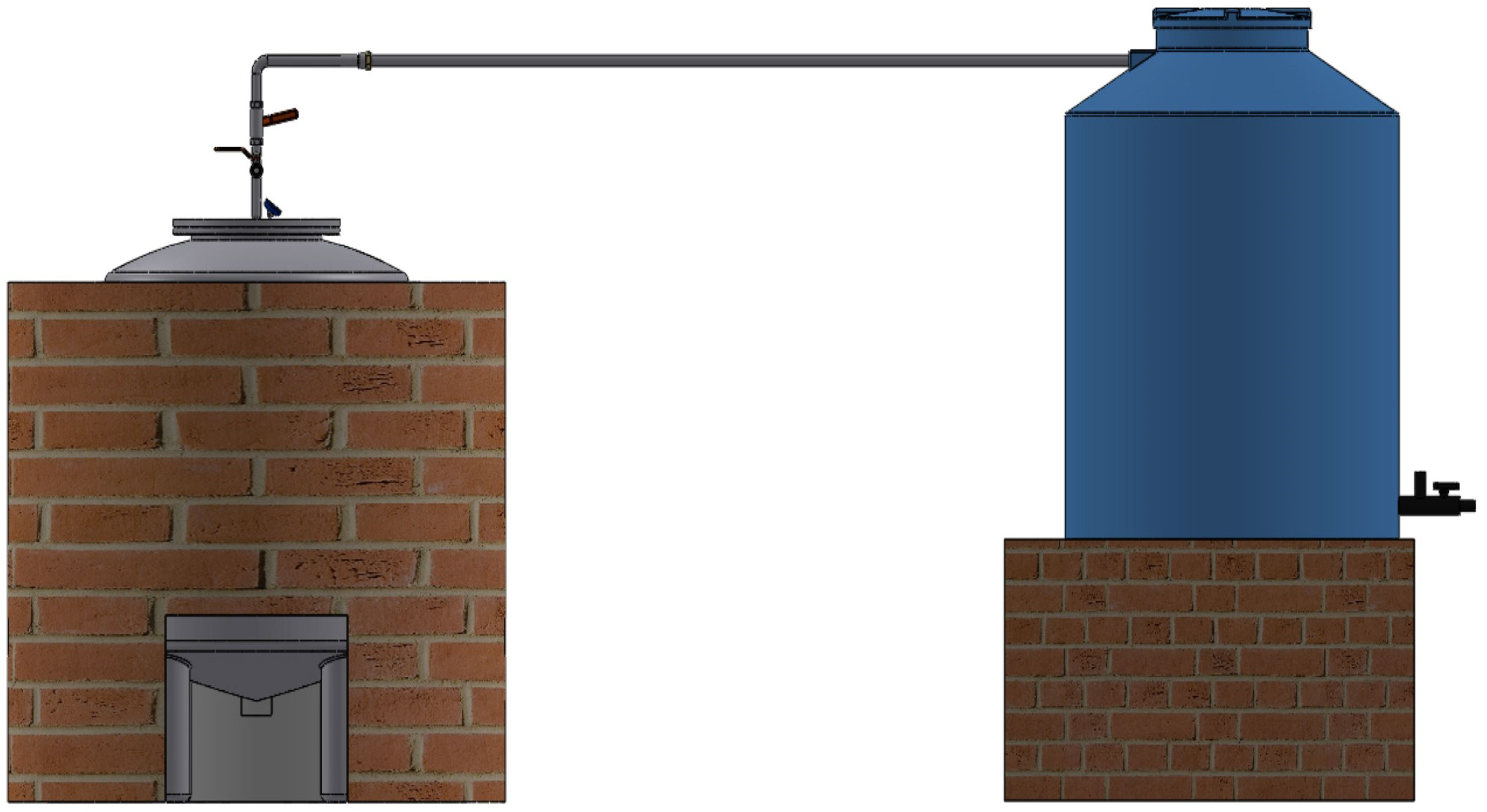
Figure 1. Prototype.
Recycling 10 00199 g001
Figure 2. Thermal simulation of the jacketed reactor at 3000 W: internal and external views.
Recycling 10 00199 g002
Figure 3. Simulation of the energy and temperature required to achieve pyrolysis at 350 °C under convection coefficients of 25 W/m2·K (open air). 10, 7, and 2 W/m2·K (closed space).
Recycling 10 00199 g003
Figure 4. Stainless steel tank for pyrolysis reactor.
Recycling 10 00199 g004
Figure 5. Tank capacity and volume, 800 L.
Recycling 10 00199 g005
Figure 6. Design of the flat flange type cover: top view (left) and bottom view (right).
Recycling 10 00199 g006
Figure 7. Flange on reactor cover and tank.
Recycling 10 00199 g007
Figure 8. Jacket for the reactor tank, (a) Red clay layer, (b) Ceramic layer, (c) Refractory cement layer, (d). View of the three layers of the jacket.
Recycling 10 00199 g008aRecycling 10 00199 g008b
Table 1. Thermal conductivity of materials used for the reactor jacket design.
MaterialThermal Conductivity
W / m · K
Thickness
m
Ceramics1.40.025
Refractory Cement1.20.01
Red clay brick0.90.12
Steel 304-2B16.20.0016
Table 2. Thermal resistance of materials.
MaterialValue of R (m2·K/W)
Ceramics0.018
Refractory cement0.0083
Red clay brick0.133
Stainless steel 304-2B0.000098
Table 3. Results of applied energy and temperature under different convection scenarios.
Radiation
Steel
Emissivity
Heat Flux
W/m2
Convection
W/m2·K
Heat Power
W
Temperature
Max. °C
Temperature
Min. °C
Surface Temperature °C
0.3656.425300026849151
0.31094.025500041166238
0.32188.02510,000697106401
0.34376.02520,0001000215659
0.3656.45103000507161265
0.31094.09105000645199310
0.31531.17107000757234364
0.31750.54108000806251375
0.32188.181010,000895285420
0.3656.4573000551214340
0.3875.2774000622234345
0.31094.0975000685255360
0.31312.9176000742276380
0.31750.5478000841316450
0.3218.021000467322400
0.3328.021500513339444
0.3437.022000556355456
0.3656.023000631387533
0.31094.025000755419587
Table 4. Chemical composition of base metal (% by weight) [51].
Thickness (mm)CMnSiCrNiMo
1.50.091.040.4417.757.690.13
2.00.050.990.5617.608.000.14
3.00.091.020.4017.978.060.20
Disclaimer/Publisher’s Note: The statements, opinions and data contained in all publications are solely those of the individual author(s) and contributor(s) and not of MDPI and/or the editor(s). MDPI and/or the editor(s) disclaim responsibility for any injury to people or property resulting from any ideas, methods, instructions or products referred to in the content.