
Recovering Attached Crude Oil from Hydrodesulfurization Spent Catalysts

Abstract
1. Introduction
2. Results and Discussion
2.1. Optimization of Extraction Process Conditions
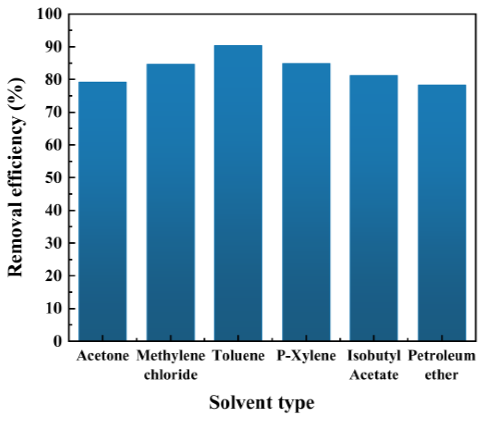
2.1.1. Selection of Extraction Agent
2.1.2. Optimization of Oil Removal Efficiency
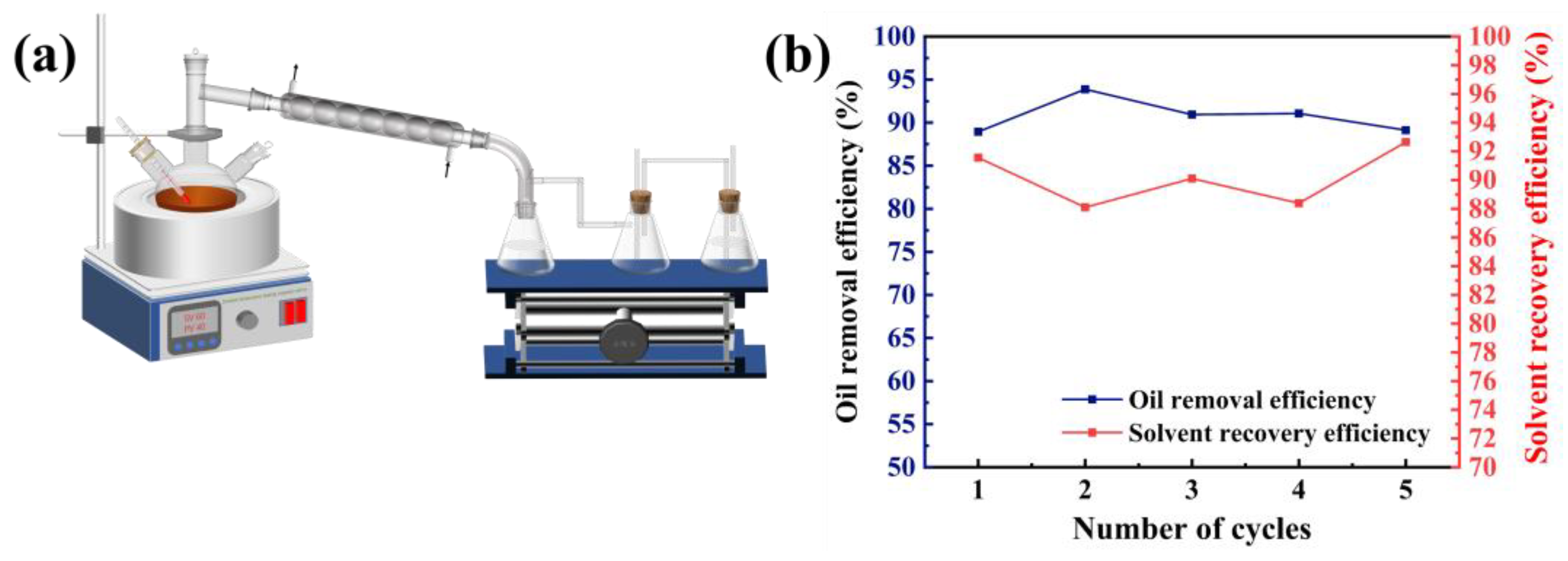
2.1.3. Solvent Recycling
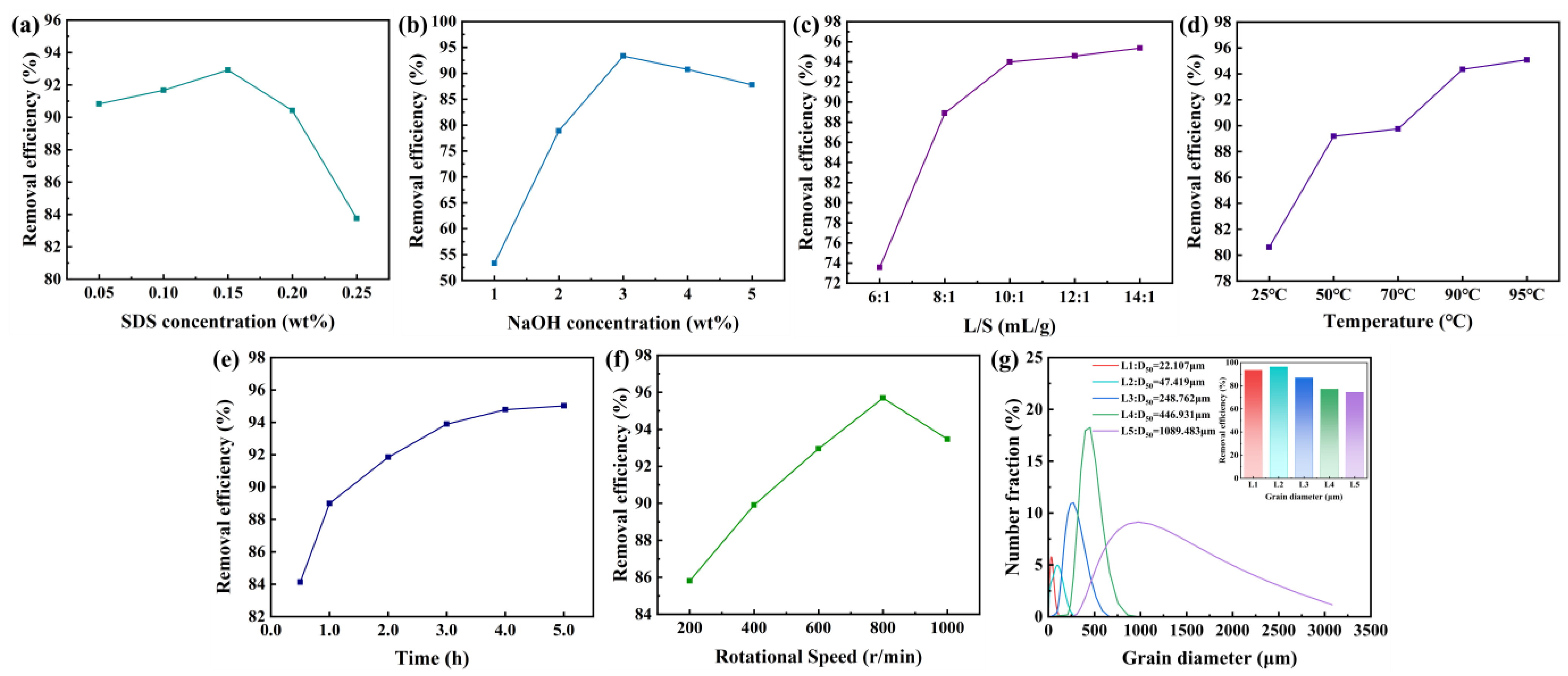
2.2. Optimization of Chemical Thermal Washing Process Conditions
2.2.1. Optimization of Oil Removal Efficiency
2.2.2. Wastewater Treatment
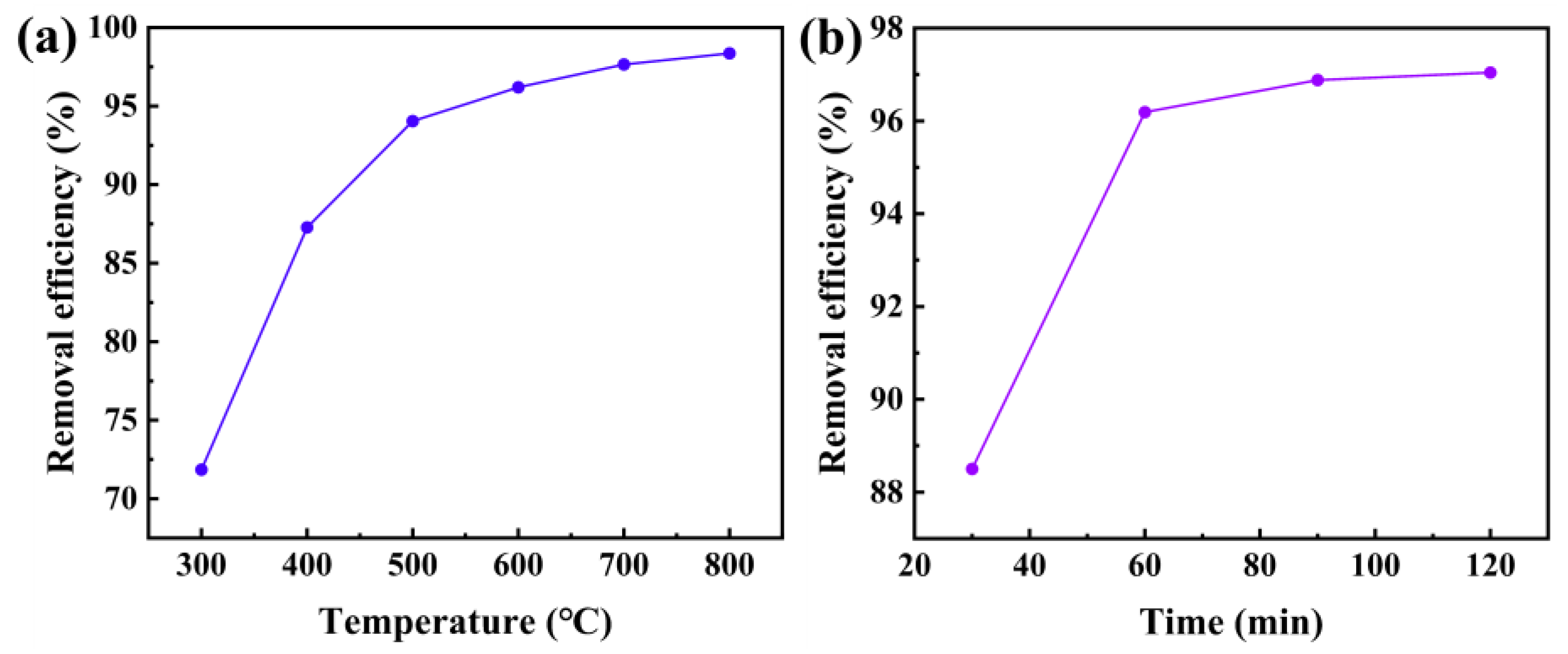
2.3. Optimization of Pyrolysis Process Conditions
2.4. Characterization
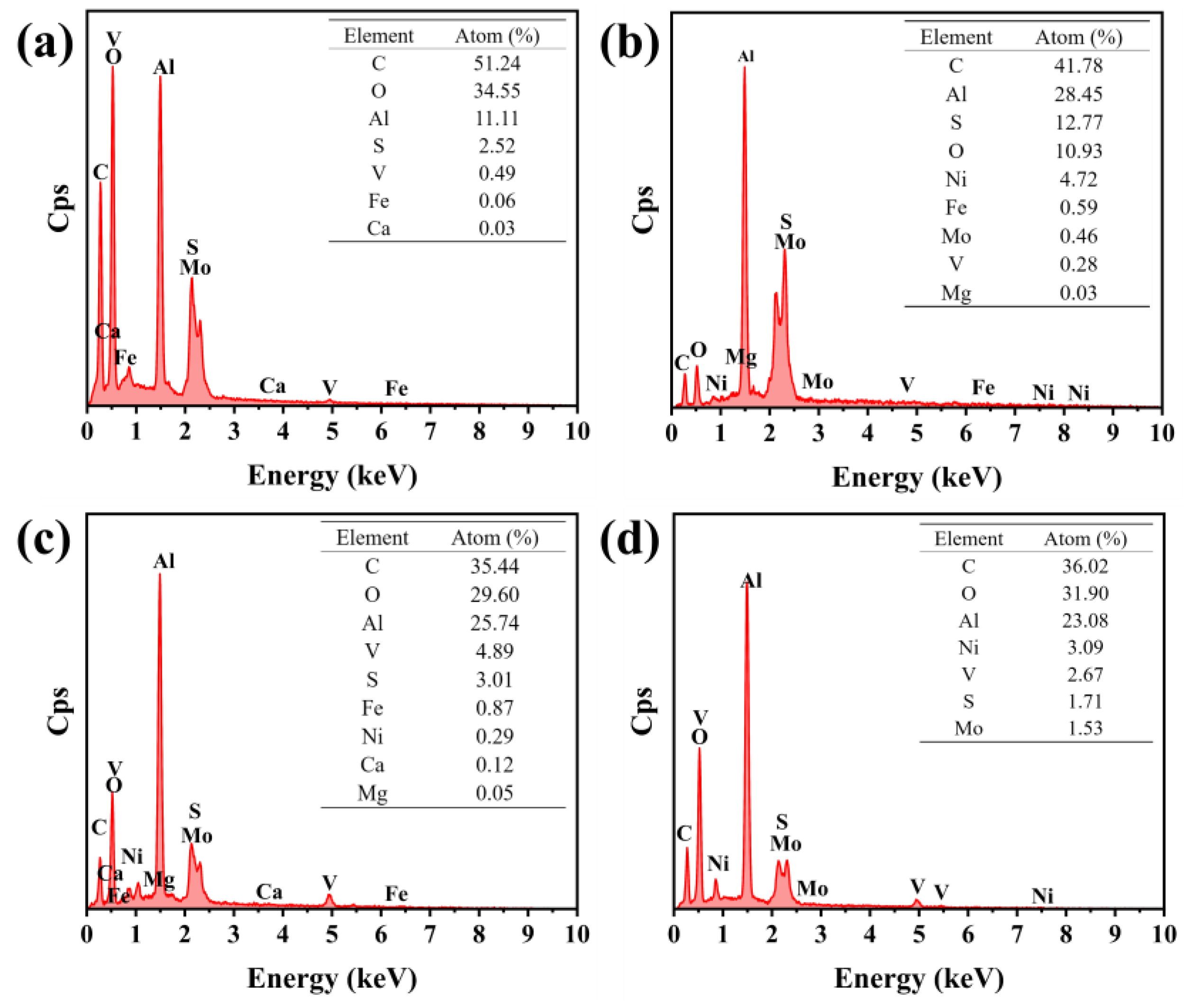
2.4.1. SEM and EDS
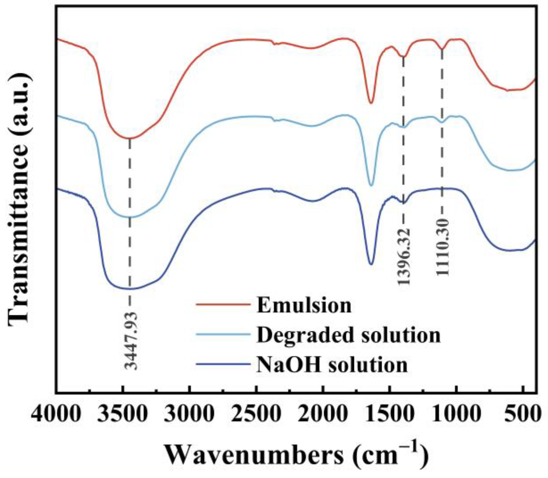
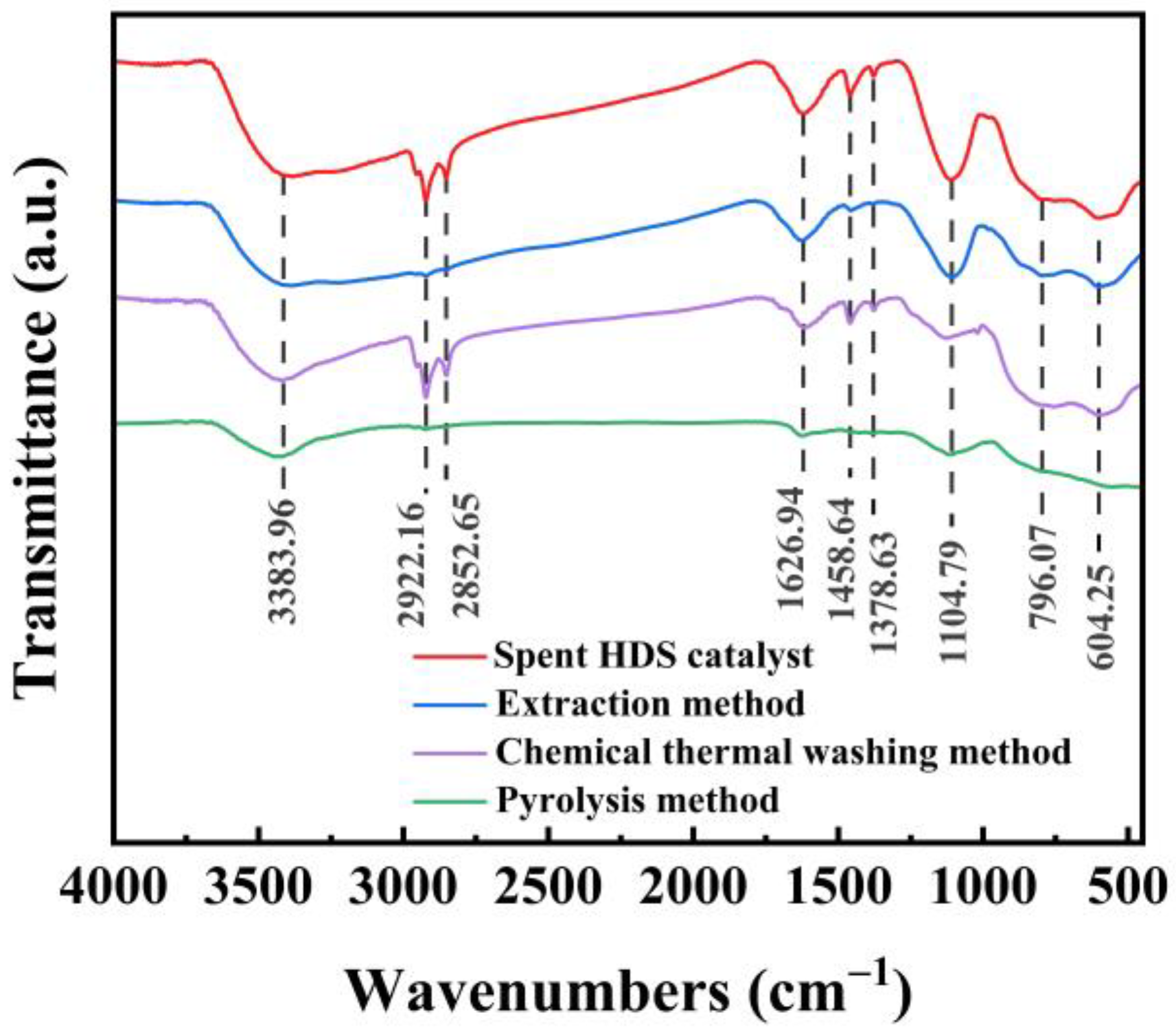
2.4.2. FT-IR
2.5. Experimental Results and Analysis
2.5.1. Experimental Results of the Three Methods
2.5.2. Environmental and Economic Impacts of Pyrolysis Method
3. Materials and Methods
3.1. Materials and Chemicals
3.2. Experimental Procedure
3.2.1. Extraction Method
3.2.2. Chemical Hot Washing Method
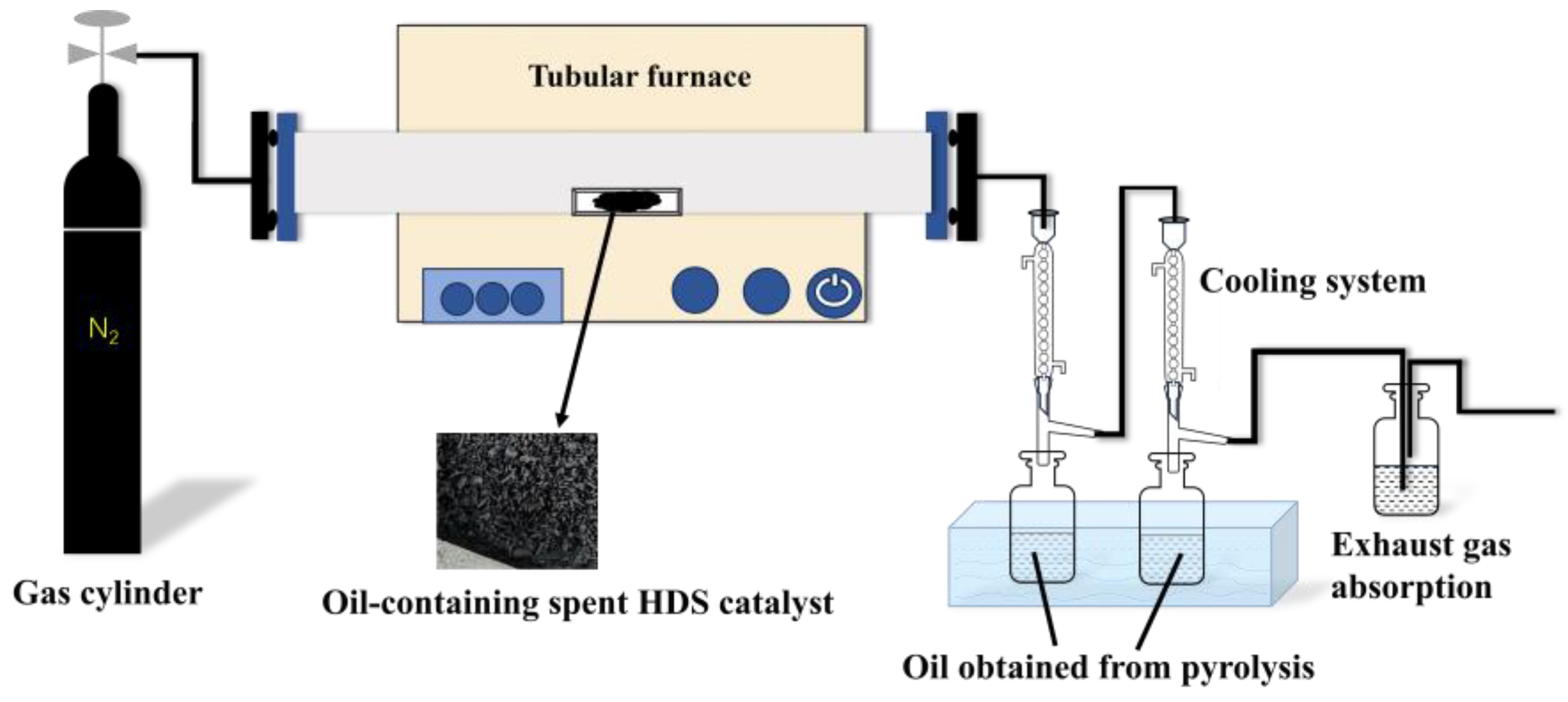
3.2.3. Pyrolysis Method
3.3. Oil Removal Efficiency Determination
3.4. Characterization
4. Conclusions
Author Contributions
Funding
Data Availability Statement
Acknowledgments
Conflicts of Interest
References
- Yang, Y.; Xu, S.; Li, Z.; Wang, J.L.; Zhao, Z.W.; Xu, Z.H. Oil removal of spent hydrotreating catalyst CoMo/Al2O3 via a facile method with enhanced metal recovery. J. Hazard. Mater. 2016, 318, 723–731. [Google Scholar] [CrossRef] [PubMed]
- Wang, J.Z.; Wang, S.N.; Olayiwola, A.; Yang, N.; Liu, B.; Weigand, J.J.; Wenzel, M.; Du, H. Recovering valuable metals from spent hydrodesulfurization catalyst via blank roasting and alkaline leaching. J. Hazard. Mater. 2021, 416, 125849. [Google Scholar] [CrossRef] [PubMed]
- Chen, Y.X.; Wu, X.S.; Guan, W.J.; Xiao, S.Y.; Fang, K.Y.; Qing, J.L.; Xie, R.; Wu, S.X.; Li, Q.G.; Cao, Z.Y.; et al. Efficient recovery of all valuable metals from spent HDS catalysts: Based on roasting mechanisms for enhanced selective leaching and separation. J. Environ. Chem. Eng. 2024, 12, 113485. [Google Scholar] [CrossRef]
- Le, M.N.; Lee, M.S. A review on hydrometallurgical processes for the recovery of valuable metals from spent catalysts and life cycle analysis perspective. Miner. Process. Extr. Metall. Rev. 2020, 42, 335–354. [Google Scholar] [CrossRef]
- Akcil, A.; Vegliò, F.; Ferella, F.; Okudan, M.D.; Tuncuk, A. A review of metal recovery from spent petroleum catalysts and ash. Waste Manag. 2015, 45, 420–433. [Google Scholar] [CrossRef] [PubMed]
- Gao, J.; Hao, M.; Wu, T.; Li, T.J. A fast and efficient method for the efficient recovery of crude oil from spent hydrodesulphurization catalyst. Colloids Surf. A Physicochem. Eng. Asp. 2022, 642, 128650. [Google Scholar] [CrossRef]
- Bikoko, T.; Okonta, F.N. Binder systems for the stabilization/solidification of contaminated soils-a review. Electron. J. Geotech. Eng. 2016, 21, 9927–9955. [Google Scholar]
- Jho, E.H.; Keum, H.; Pyo, S.Y.; Kang, G.Y. Hemoglobin-Catalyzed Oxidation for Remediation of Total Petroleum Hydrocarbons Contaminated Soil. Clean–Soil Air Water 2016, 44, 654–656. [Google Scholar] [CrossRef]
- Tran, H.T.; Lin, C.; Bui, X.T.; Ngo, H.H.; Cheruiyot, N.K.; Hoang, H.G.; Vu, C.T. Aerobic composting remediation of petroleum hydrocarbon-contaminated soil. Current and future perspectives. Sci. Total Environ. 2021, 753, 142250. [Google Scholar] [CrossRef] [PubMed]
- Vidonish, J.E.; Zygourakis, K.; Masiello, C.A.; Sabadell, G.; Alvarez, P.J.J. Thermal treatment of hydrocarbon-impacted soils: A review of technology innovation for sustainable remediation. Engineering 2016, 2, 426–437. [Google Scholar] [CrossRef]
- Shi, D.; Huang, Y.; Wang, H.L.; Yuan, W.; Fu, P.B. Deoiling of oil-coated catalyst using high-speed suspending self-rotation in cyclone. Sep. Purif. Technol. 2019, 210, 117–124. [Google Scholar] [CrossRef]
- Chang, C.Y.; Shie, J.L.; Lin, J.P.; Wu, C.H.; Lee, D.J.; Chang, C.F. Major products obtained from the pyrolysis of oil sludge. Energy Fuels 2000, 14, 1176–1183. [Google Scholar] [CrossRef]
- Yang, Y.; Cao, T.T.; Xiong, Y.; Huang, G.Y.; Wang, W.Q.; Liu, Q.; Xu, S.M. Oil removal from spent HDT catalyst by an aqueous method with assistance of ultrasound. Waste Manag. 2018, 78, 595–601. [Google Scholar] [CrossRef] [PubMed]
- Common Organic Solvent Polarity Table. Available online: http://www.cnreagent.com/show1000005/technical_11.html (accessed on 2 June 2024).
- Hu, G.J.; Li, J.B.; Hou, H.B. A combination of solvent extraction and freeze thaw for oil recovery from petroleum refinery wastewater treatment pond sludge. J. Hazard. Mater. 2015, 283, 832–840. [Google Scholar] [CrossRef] [PubMed]
- Wang, M.X.; Zhang, B.; Li, G.R.; Wu, T.; Sun, D.J. Efficient remediation of crude oil-contaminated soil using a solvent/surfactant system. RSC Adv. 2019, 9, 2402–2411. [Google Scholar] [CrossRef] [PubMed]
- Wang, L.; Chao, L.; Qu, W.W.; Xu, S.M.; Zhang, L.B.; Peng, J.H.; Ye, X.L. Ultrasound-assisted oil removal of γ-Al2O3-based spent hydrodesulfurization catalyst and microwave roasting recovery of metal Mo. Ultrason. Sonochem. 2018, 49, 24–32. [Google Scholar] [CrossRef]
- Kheireddine, H.A.; El-Halwagi, M.M.; Elbashir, N.O. A property-integration approach to solvent screening and conceptual design of solvent-extraction systems for recycling used lubricating oils. Clean Technol. Environ. Policy 2013, 15, 35–44. [Google Scholar] [CrossRef]
- Liu, J.W.; Wei, K.H.; Xu, S.W.; Cui, J.; Ma, J.; Xiao, X.L.; Xi, B.D.; He, X.S. Surfactant-enhanced remediation of oil-contaminated soil and groundwater: A review. Sci. Total Environ. 2021, 756, 144142. [Google Scholar] [CrossRef]
- Huo, L.L.; Liu, G.S.; Li, Y.; Yang, X.; Zhong, H. Solubilization of residual dodecane by surfactants in porous media: The relation between surfactant partition and solubilization. Colloids Surf. A Physicochem. Eng. Asp. 2022, 648, 129421. [Google Scholar] [CrossRef]
- Gong, H.J.; Li, Y.J.; Dong, M.Z.; Ma, S.Z.; Liu, W.R. Effect of wettability alteration on enhanced heavy oil recovery by alkaline flooding. Colloids Surf. A Physicochem. Eng. Asp. 2016, 488, 28–35. [Google Scholar] [CrossRef]
- Chen, G.; Cheng, C.; Zhang, J.; Sun, Y.; Hu, Q.; Qu, C.T.; Dong, S.B. Synergistic effect of surfactant and alkali on the treatment of oil sludge. J. Pet. Sci. Eng. 2019, 183, 106420. [Google Scholar] [CrossRef]
- Wilt, B.K.; Welch, W.T.; Rankin, J.G. Determination of asphaltenes in petroleum crude oils by Fourier transform infrared spectroscopy. Energy Fuels 1998, 12, 1008–1012. [Google Scholar] [CrossRef]
- Al-Sheeha, H.; Marafi, M.; Raghavan, V.; Rana, M.S. Recycling and recovery routes for spent hydroprocessing catalyst waste. Ind. Eng. Chem. Res. 2013, 52, 12794–12801. [Google Scholar] [CrossRef]
- Sun, D.W.; Wang, Y.J.; Gao, J.; Liu, S.J.; Liu, X.L. Insights into the relation of crude oil components and surfactants to the stability of oily wastewater emulsions: Influence of asphaltenes, colloids, and nonionic surfactants. Sep. Purif. Technol. 2023, 307, 122804. [Google Scholar] [CrossRef]
- Hoffmann, J.; Jensen, C.U.; Rosendahl, L.A. Co-processing potential of HTL bio-crude at petroleum refineries–Part 1: Fractional distillation and characterization. Fuel 2016, 165, 526–535. [Google Scholar] [CrossRef]
- Colati, K.A.P.; Dalmaschio, G.P.; Castro, E.V.R.D.; Gomes, A.O.; Vaz, B.G.; Romao, W. Monitoring the liquid/liquid extraction of naphthenic acids in brazilian crude oil using electrospray ionization FT-ICR mass spectrometry (ESI FT-ICR MS). Fuel 2013, 108, 647–655. [Google Scholar] [CrossRef]
- Castro, L.V.; Vazquez, F. Fractionation and characterization of Mexican crude oils. Energy Fuels 2009, 23, 1603–1609. [Google Scholar] [CrossRef]
- Wang, R.X.; Wen, T.; Wu, X.L.; Xu, A.W. Highly efficient removal of humic acid from aqueous solutions by Mg/Al layered double hydroxides–Fe3O4 nanocomposites. RSC Adv. 2014, 4, 21802–21809. [Google Scholar] [CrossRef]
- Srichandan, H.; Singh, S.; Blight, K.; Pathak, A.; Kim, D.J.; Lee, S.; Lee, S.W. An integrated sequential biological leaching process for enhanced recovery of metals from decoked spent petroleum refinery catalyst: A comparative study. Int. J. Miner. Process. 2015, 134, 66–73. [Google Scholar] [CrossRef]
- Andersen, S.I.; Mahavadi, S.C.; Abdallah, W.; Buiting, J.J. Infrared spectroscopic analysis of the composition of an oil/water interfacial film. Energy Fuels 2017, 31, 8959–8966. [Google Scholar] [CrossRef]
- Park, J.Y.; Kariim, I.; Amini, G.; Kong, Y.J.; Kazmi, W.W.; Lee, I.G. Bio-Oil Production by Depolymerization and Hydrodeoxygenation of Lignins over Mg–Ni–Mo/Activated Charcoal in Supercritical Ethanol. Energy Fuels 2024, 38, 20747–20761. [Google Scholar] [CrossRef]
- Inchaurrondo, N.; Contreras, E.; Haure, P. Catalyst reutilization in phenol homogeneous cupro-Fenton oxidation. Chem. Eng. J. 2014, 251, 146–157. [Google Scholar] [CrossRef]


| Solvent | Polarity | Boiling Point (°C) |
|---|---|---|
| Petroleum ether | 0.01 | 30–60 |
| Toluene | 2.4 | 110.6 |
| P-Xylene | 2.5 | 138.4 |
| Methylene chloride | 3.4 | 39.8 |
| Acetone | 5.4 | 58.08 |
| Isobutyl acetate | — | 116 |
| Oil Removal Method | Untreated Spent HDS Catalyst | Spent HDS Catalyst Treated with the Extraction Method | Spent HDS Catalyst Treated with the Chemical Thermal Washing Method | Spent HDS Catalyst Treated with the Pyrolysis Method | |
|---|---|---|---|---|---|
| Atomic content of major elements (%) | C | 51.24 | 41.78 | 35.44 | 36.02 |
| O | 34.55 | 10.93 | 25.74 | 31.90 | |
| Al | 11.11 | 28.45 | 24.74 | 23.08 | |
| V | 0.49 | 0.28 | 4.89 | 2.67 | |
| Mo | — | 0.46 | — | 1.53 | |
| N | — | 4.72 | 0.29 | 3.09 | |
| Types of Methods | Extraction Method | Chemical Hot Washing Method | Pyrolysis Method | |
|---|---|---|---|---|
| Process Conditions | Extractant | Toluene | — | |
| Concentration of Surfactant | — | 0.15 wt.% SDS | — | |
| Concentration of Alkali | — | 3.0 wt.% NaOH | — | |
| L/S (mL/g) | 10:1 | 10:1 | — | |
| Temperature (°C) | 45 | 90 | 600 | |
| Time (min) | 60 | 240 | 60 | |
| Stirring Speed (rpm/min) | 300 | 800 | — | |
| Particle size of spent catalyst (µm) | 47.419 | 47.419 | Not ground | |
| Gas atmosphere | Air | Air | Inert gas (N2) | |
| Oil removal efficiency (%) | 94.12 | 96.26 | 96.19 | |
| Waste liquid volume (mL) | 45 (One-time generated amount) | 47 (One-time generated amount) | 250 (Amount generated after multiple uses) | |
Disclaimer/Publisher’s Note: The statements, opinions and data contained in all publications are solely those of the individual author(s) and contributor(s) and not of MDPI and/or the editor(s). MDPI and/or the editor(s) disclaim responsibility for any injury to people or property resulting from any ideas, methods, instructions or products referred to in the content. |
© 2025 by the authors. Licensee MDPI, Basel, Switzerland. This article is an open access article distributed under the terms and conditions of the Creative Commons Attribution (CC BY) license (https://creativecommons.org/licenses/by/4.0/).
Share and Cite
Hong, X.; Chen, J.; Wei, J.; Wu, W.; Yang, Z.; Chen, J.; Sun, S.; Xiao, F.; Tu, G. Recovering Attached Crude Oil from Hydrodesulfurization Spent Catalysts. Recycling 2025, 10, 10. https://doi.org/10.3390/recycling10010010
Hong X, Chen J, Wei J, Wu W, Yang Z, Chen J, Sun S, Xiao F, Tu G. Recovering Attached Crude Oil from Hydrodesulfurization Spent Catalysts. Recycling. 2025; 10(1):10. https://doi.org/10.3390/recycling10010010
Chicago/Turabian StyleHong, Xin, Jingyi Chen, Jing Wei, Wenjie Wu, Ziyan Yang, Jing Chen, Shuchen Sun, Faxin Xiao, and Ganfeng Tu. 2025. "Recovering Attached Crude Oil from Hydrodesulfurization Spent Catalysts" Recycling 10, no. 1: 10. https://doi.org/10.3390/recycling10010010
APA StyleHong, X., Chen, J., Wei, J., Wu, W., Yang, Z., Chen, J., Sun, S., Xiao, F., & Tu, G. (2025). Recovering Attached Crude Oil from Hydrodesulfurization Spent Catalysts. Recycling, 10(1), 10. https://doi.org/10.3390/recycling10010010