Article

Silicon/Carbon Nanoparticles Assembled with Multifunction Carbon Nanotubes/Sheets as High-Performance Anode of Lithium-Ion Batteries

1
School of Materials and Energy, Guangdong University of Technology, Guangzhou 510006, China
2
Department of Mechanical and Aeronautical Engineering, Hong Kong University of Science & Technology, Hong Kong 999077, China
3
Department of Electrical Engineering, Shanghai Jiao Tong University, Shanghai 200240, China
*
Author to whom correspondence should be addressed.
Batteries 2023, 9(9), 460; https://doi.org/10.3390/batteries9090460
Submission received: 21 July 2023 / Revised: 1 September 2023 / Accepted: 7 September 2023 / Published: 11 September 2023

Abstract

:
Silicon as an electrode material in the lithium-ion battery application scenario has been hindered by its significant volumetric expansion and intricate synthesis processes. In this research, we have successfully synthesized Si@C/carbon nanotubes/carbon sheets (Si@C-CNTs/CS) composites by employing a simple one-pot method along with modified magnesium thermal reaction, which involves melamine to prevent high temperature. The resulting multifunctional Si@C-CNTs/CS composites demonstrate enhanced stability during volume change in silicon, resulting in both higher capacity compared to conventional carbon coating layer and improved conductivity of the materials. The results indicate that the Si@C-CNTs/CS composites exhibit a high discharge-specific capacity of up to 2981.64 mAh g−1 at 0.5 A g−1 current density and retain a discharge-specific capacity of 1487.71 mAh g−1 even after 300 cycles. Therefore, the double-layer carbon network structure of carbon nanotubes/carbon nanosheets can provide an efficient and simple preparation method for high-performance Si-base anode materials in practical applications.

1. Introduction

The widespread use of traditional fossil fuels has resulted in large amounts of greenhouse gases and atmospheric pollution, highlighting the importance of developing green and renewable energy sources. Governments around the world are increasingly prioritizing efficient energy research and clean energy utilization to meet both market demand and environmental protection goals [1]. Lithium-ion batteries with excellent energy density, efficiency, low self-discharge, a long cycling life, environmental compatibility and other merits have attracted much attention. These batteries have been widely applied in mobile power applications, smart grids and electric vehicles, which will become a crucial component of modern energy systems [2,3].
Although graphite has an excellent cycling performance and is widely used as an anode material, it has limitations in meeting energy density requirements [4,5,6]. Silicon, on the other hand, has garnered considerable interest as a prospective anode material, owing to silicon’s exceptional theoretical specific capacity of 4200 mAh g−1 and lithiation potential that ensures safety, thereby positioning it as a formidable contender for replacing graphite [7,8,9,10]. However, silicon also has obvious drawbacks such as significant volume expansion (~300%) during the cycling process, leading to a poor cycling performance and low electrochemical performance [11]. Moreover, the volume variation effect of a silicon anode can lead to cracking and pulverization, further contributing to capacity degradation during the cycling processes. The methods for preparing Si/C anode include molten salt approach [12], atomic layer deposition [13] and the vacuum arc method [14]. Generally, metal thermal reduction reactions are frequently employed for the reduction of naturally abundant silica resources to obtain silicon particles. Common metal thermal reduction reactions include magnesiothermic reduction and aluminothermic reduction. Compared with the metal-assisted etching method, the magnesiothermic reduction is a suitable approach to largely synthesis without extra reaction equipment. Nevertheless, the electrical and mechanical integrity of the silicon anode is still needed to improve. To date, there are many researchers that have endeavored to effectively solve these problems. The micron/nanostructures are inserted into short transfer paths of lithium ions and electrons, which can improve the electrical conductivity of the silicon anode [15,16,17]. In addition, the weak interfacial interaction between the collector and silicon surface may result in crack and exfoliation; thus, some binders are utilized to confirm the anode material in order to strengthen the cycling performance [18,19,20,21]. In addition, silicon-based anodes with different morphologies such as nanospheres, nanowire, and a porous structure are designed to decrease the stress via the Si volume effect.
One promising strategy to overcome the issue of volume expansion of silicon anode is utilizing the silicon/carbon structure composite material. These structures can effectively buffer the volume effect of silicon anode with various microstructures, such as synthesizing nanoparticle/carbon composites with egg yolk shell structures [22], carbon nanotube-Si composites [23], and amorphous carbon-covered Si composites. However, the traditional silicon/carbon electrodes are unable to be uniformly distributed in the composite material, which restricts their capability to improve electrical conductivity and shorten Li-ion transport distance.
In recent years, the design and synthesis of silicon anode frameworks composed of carbon sheets and carbon nanotubes (CNTs) have emerged as a development prospect strategy of high-performance LIBs [23]. The carbon sheets play the active matrix role to enhance electrical conductivity [24] and also act as a protective layer that can mitigate the impact of volume changes that occur during charge and discharge processes. Through the integration of CNTs among the silicon anode, electrical conductivity is improved owing to the reduction in the transferring paths for lithium ions and electrons [25,26]. However, the cyclic stability of such anode requires further improvement. The CNTs integrated between carbon sheets can not only enable the formation of a stable network to prevent aggregation, but also serve as “welding points” to facilitate the carrier transport within the inner anode and enhance lithium-ion transportation and electrolyte infiltration. Thus, the interconnected silicon/CNTs/carbon sheet composite is a simple and environmentally friendly approach that has great potential to obtain excellent performance anode materials for LIBs.
This study proposes a simple and environmentally friendly approach to fabricate Si@C-CNTs/CS, a high-performance anode material for lithium-ion batteries (LIBs), using the modified extensible magnesium thermal reduction method [27] coupled with a pyrolysis of melamine strategy [28]. The double-layer carbon mesh structure containing carbon nanotubes and carbon sheets not only improves electrical conductivity, but also provides mechanical flexibility and a rich pore structure, which can help to alleviate the expansion of volume during the cycling processes. The excellent cycling stability, high reversible capacity, and high electrochemical stability observed in this study demonstrate the potential of Si@C-CNTs/CS as a practical and high-performance anode material for LIBs. Therefore, this study can provide a valuable guideline on the designation of novel Si-base anode for improving the performance of LIBs.

2. Experiment

2.1. Materials

Magnesium powders (100–200 M), sodium chloride (99.9%) and ethanol (>99.7%) were purchased from Sinopharm (Beijing, China). Ammonium hydroxide (37%wt), Melamine (99%) and resorcinol (99%) were purchased from Aladdin (Shanghai, China). Cobaltous nitrate hexahydrate (99.99%), liquid paraffin were purchased from Macklin (Shanghai, China). Tetraethyl orthosilicate (99%) was purchased from Tianjin Zhiyuan (Tianjin, China).

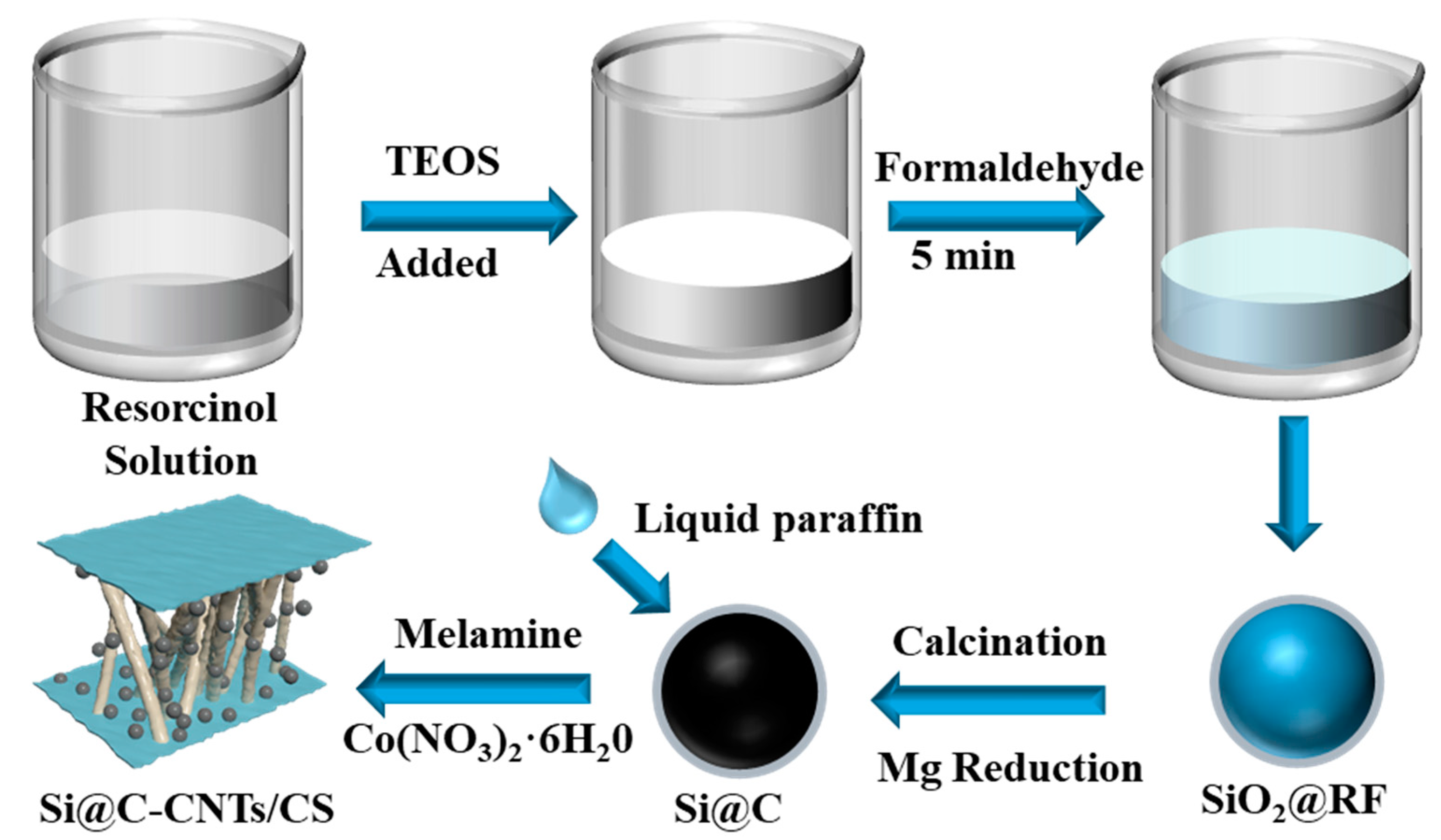
2.2. Synthesis of SiO2@C

The SiO2@RF (Phenolic resin, hereinafter referred to as RF) was synthesized by using a sol–gel method. In total, 100 mg of resorcinol was first dissolved in 300 mL of a solution mixture made up of ethanol and deionized water (volume ratio 9:1, noted as E/W = 9), followed by the addition of 9 mL of ammonium hydroxide. Subsequently, 8.1 mL of tetraethyl orthosilicate was instilled and magnetically stirred for 5 min. The 140 μL of methanal was instilled and stirring was continued for 24 h. Additionally, the reaction was subsequently collected via centrifugation. The product was soaked in deionized water and then washed with ethanol several times; the centrifugation operation was repeated, and then dried at 60 °C for 12 h. The SiO2@RF was calcined for 180 min (raising to 900 °C at 2 °C/min) in an argon atmosphere to obtain the target product.

2.3. Synthesis of Si@C

To efficiently obtain Si@C, a modified magnesium heat reaction was sufficiently mixed with the Mg and sodium chloride powder. Sodium chloride is in full contact with magnesium powder, which facilitates the absorption of redundant localized heat generated in MR. First of all, 400 mg of Mg and 2 g of sodium chloride were milled at 200 rpm for two hours, and subsequently ground well with 400 mg of SiO2@C with mortar and pestle, and then raising at 650 °C for 1 h in an argon atmosphere with the magnesium thermal reduction. Finally, the excess magnesium powder is removed via acid washing to get the Si@C.

2.4. Synthesis of Si@C-CNTs/CS

The Si@C (400 mg) and melamine (2.4 g) were ground uniformly in paraffin oil. Subsequently, the 160 mg of cobaltous nitrate hexahydrate was dissolved in 10 mL ethanol, which was stirred continually and dropped to Si@RF and melamine ground in liquid paraffin. After grounding sufficiently, it was calcined under an argon atmosphere at 950 °C for 2 h at a raising rate of 2 °C/min, which aimed to produce Si@C-CNTs/CS.

2.5. Material Characterizations

The SEM (Hitach SU8220) was used to reveal the microscopic surface appearance of the samples, while the TEM (FEI Tecnai G2F 20) was used to investigate the internal structure and crystallographic properties. The XRD (D/MAX-Ultima Ⅵ) was used for determining the crystal structure and phase purity of composites. Then, the XPS (PHI-5000versaprobeIII) was utilized to study the composition and properties of surfaces and the electronic structure at the surface of the samples. Confocal micro-Raman spectroscopy (Horiba Jobin Yvon LABRAM HR 800UV) was used to investigate the molecular vibrational modes and structural properties of the samples. Finally, the BET test (Micrometrics ASAP 2460) was used to evaluate parameters such as adsorption, reaction and transport properties of the materials. All measurements were performed under controlled conditions, and the results were interpreted based on established theories and models in materials science.

2.6. Electrochemical Characterizations

The working electrode involved a careful mixing of the active substance (pure Si, Si@C or Si@C-CNTs/Cs), sodium alginate binder, and conductive agent (Acetylene black or Super P) in a certain weight ratio. In this study, the weight ratio of the three components was 7:1.5:1.5. The resulting mixture was then homogenized by adding a specific amount of deionized water and grinding. The mass loading of the active material in the electrode was 0.85 mg cm−2. Subsequently, the evenly mixed slurry was applied to the copper foil and dried in a vacuum-drying oven at 55 °C for 10 h. The utilized button cell model was R2032. The button cell was assembled within a glove box (O2 content is less than 0.1 × 10⁻⁶ pm, H2O content is less than 0.1 × 10⁻⁶ pm), utilizing a lithium metal sheet as the reference electrode, polypropylene film as the diaphragm, and silicon carbon button electrolyte (1 M LiPF6, KLD-SiO1) as the electrolyte, and assembled in a certain order. Constant current charge/discharge tests were conducted at room temperature on a charge/discharge test cabinet (NEWAER-CT-4008). AC impedance tests were performed on the CHI7603 workstation.

3. Results and Discussion

The Si@C-CNTs/CS material obtained in this study is composed of Si nanoparticles, carbon nanotubes (CNTs), and nitrogen-doped carbon sheets. As shown in Figure 1, the synthesis process involves the use of RF-coated SiO2 spheres as a precursor material, which utilized the RF as a carbon source and carbonized at high temperature to produce Si@C spheres. Then, Si@C melamine is ground into a uniform mixture and dissolved in paraffin oil. Then, cobalt nitrate ethanol solution hexahydrate is added drop by drop. Then, high temperature pyrolysis is performed to generate Si@C-CNTs/CS. For the reduction of SiO2 spheres, a modified magnesiothermic reduction reaction was used. At high temperatures, sodium chloride transforms from a solid to a molten state, providing a “liquid” environment for magnesium. In its molten state, sodium chloride ionizes out chloride and sodium ions and absorbs heat. At the same time, magnesium has some solubility in molten sodium chloride and can ionize into magnesium ions and electrons. Due to the strong reducing ability of magnesium ions, it rapidly reacts with SiO2 at a high temperature. In this process, in addition to the reduction of SiO2, there are some side reactions leading to the production of Mg2Si and MgO. The chemical reaction is as follows [29,30]:
2 M g + S i O 2 = 2 M g O + S i
S i O 2 + 2 M g = S i + 2 M g O
S i + 2 M g = M g 2 S i
4 M g + S i O 2 = M g 2 S i + 2 M g O
S i O 2 + M g 2 S i = 2 S i + 2 M g O
Although the by-products M g 2 S i and M g O produced in the reduction reaction can be removed via hydrochloric acid immersion and other methods, the obtained Si will agglomerate together in this process, resulting in a certain impact on its electrochemical properties. The “liquid” environment provided by sodium chloride during the reduction process is good for preventing the agglomeration of silicon [28]. During the pyrolysis process, melamine is thermally condensed to generate a graphitic carbon nitride (g-C3N4) layer. Co ions are confined in the layered g-C3N4 and generate aromatic intermediates. As the pyrolysis temperature is increased, the cobalt atoms are further confined in the g-C3N4 layer, which catalyzes the formation of CNTs from the pyrolysis products NH3 and C2N2. Meanwhile, the g-C3N4 layer is entirely pyrolyzed to produce nitrogen. These carbon atoms form small and filmy nitrogen-dcurreoped carbon sheets [31,32]. The resulting Si@C-CNTs/CS material consists of a network of silicon particles encapsulated in amorphous carbon and interconnected by CNTs and carbon sheets.
As depicted in Figure 2a,b, the SEM images reveal the microcosmic structural morphology of the Si@C-CNTs/CS material, consisting of carbon-coated silicon particles with bilayer carbon networks of carbon nanotubes/carbon sheets. Figure 2c illustrates the presence of Si nanoparticles that are implanted within filmy layers of carbon sheets. Additionally, in Figure 2d, it depicts carbon-encapsulated Si nanoparticles within bilayer networks of carbon nanosheets and carbon nanotubes, which exhibit particle sizes between 80 and 100 nm. Notably, the external of the Si nanoparticles is decorated with carbon nanotubes having a pipe diameter about 20 nm, which form a “highway” conductive path via inter-tube interactions. This unique architecture of carbon encapsulation offers superior protection to Si nanoparticles, thereby mitigating their structural degradation upon cycling. Figure 2e illustrates the effective encapsulation of Si by amorphous carbon layers. As depicted in Figure 2h, it reveals the crystal plane spacing of 0.2012 nm, indicating the presence of the (220) crystal plane of silicon (PDF#27-1402). Meanwhile, the Si particles are tightly wrapped through a graphitized carbon layer with a 0.3377 nm space. The diffraction pattern rings match with the (111), (220) and (311) crystallographic surfaces of silicon. During the preparation of Si@C-CNTs/CS material, when melamine is pyrolyzed to form carbon nanoparticles, Si particles could be firmly adsorbed on the carbon layer due to the stable covalent interaction between Si and carbon layer. Additionally, a few Co atoms can catalyze the formation of carbon nanotubes from the NH3 and C2N2 pyrolysis products, forming a dense double-layer carbon network. In Figure 2i–l, it shows the energy dispersive spectrum (EDS) images with the Si, C, N and O elemental distribution, revealing the uniform distribution of Si in the carbon matrix consisting of N-doped carbon nanotubes and carbon sheets.
To deeply analyze the chemical structure and crystalline phase structure, Figure 3a demonstrates the XRD spectra of silicon, Si@C, and the Si@C-CNTs/CS composite. These samples exhibit prominent peaks at 2θ angles of 28.4° (111), 47.3° (220), 56.1° (311), 69.1° (400), and 76.4° (331), consistent with the faces of silicon (PDF#27-1402). Raman spectra were obtained based on measurements of the scattered light of the pair laser based on bare silicon, SI@C, and Si@C-CNTs/CS samples, as shown in Figure 3b. As the result of the vibrational movements of silicon Raman phonons [33], the Raman spectra displays the peaks around 470 cm−1, 520 cm−1, and 960 cm−1, respectively. In the meantime, the degree of graphitization in a material is often deduced from the peak intensity ratio between the D and G bands (ID/IG). The D band reflects the amorphous and defect structure, while the G band represents the graphite structure in the material. Therefore, a material with a higher degree of graphitization will have a smaller intensity ratio between the D and G bands, and its electrical conductivity will be greater [34]. The ID/IG ratio of Si@C-CNTs/CS sample is found to be only 0.88, while that of the Si@C sample is significantly higher at 1.21, indicating that the former exhibits a higher extent of graphitization and excellent electrical conductivity. The nitrogen adsorption/desorption isotherms were investigated for the three samples, as illustrated in Figure 3, with respective specific surface areas of 53.9 m2 g−1, 91.4 m2 g−1, and 206.3 m2 g−1. Due to the presence of carbon sheets, the Si@C-CNTs/CS materials exhibit the maximum specific surface area, which is beneficial for improving lithium-ion efficiency and effectively mitigating the volume expansion effect of Si. In Figure 3d, it displays the conspicuous peaks of C, N, O, and Si 2 p with binding energies of 285.1, 398.4, 533.1, 154.9, and 103.8 eV, which reveals that an O signal is observed in the XPS wide spectrum.
The chemical composition and related valence states of Si@C-CNTs/CS were determined via X-ray photoelectron spectroscopy. Figure 4a presents the spectrum of the C 1 s, which exhibits three distinctive bands at 284.7 eV, 285.9 eV, and 291.1 eV. The primary peak detected at 284.7 eV reveals the Sp2 hybridization of C-C/C=C bond, which confirms the arrangement of C atoms into the embedded honeycomb lattice. Meanwhile, two minor peaks are observed at 285.9 eV and 291.1 eV, respectively, which can be associated with the O-C=O and C-N/C=N functional groups [35]. This demonstrates that the carbon indeed contains oxygen groups. In Figure 4b, the fine spectrum of N 1 s is shown, which clearly displays the presence of three distinct peaks at 404.9 eV, 401.3 eV, and 398.3 eV, representing graphitic paper nitrogen, pyrrole nitrogen, and pyridine nitrogen, respectively [36,37]. Among these, the pyrrole nitrogen and pyridine nitrogen contained 87.4%. The existence of these functional groups significantly enhances the electrochemical activity of the carbon matrix, leading to improvements in the Si@C-CNTs/CS composite lithium storage performance. In Figure 4c, the fine spectrum of O 1 s with two distinct peaks at 533.7 eV and 536.4 eV, separately, is shown. The former peak is the Si-O bond formed due to the capture of O2 from the surrounding air by the silicon particles, which leads to a mild oxidation reaction. The latter is represented by the O-C-O bonds that still exist during the annealing process. Figure 4d displays the Si 2 p spectrum demonstrating peaks at 99.7 eV and 101.3 eV, corresponding to monatomic Si. Furthermore, the Si-N and Si-O bonds are identifiable by the peaks at 103.5 eV and 105.1 eV, respectively [36,38,39]. It reveals that the interface is strongly bonded among the Si particles and the carbon matrix, which makes the composite material have good electrical conductivity when a lithium-ion battery electrode is used.
In Figure 5a, the charge/discharge voltage distributions of the initial cycle of pure Si, Si@C and Si@C-CNTs/CS electrodes in the voltage range 0.01–1.5 V, 0.1 A g−1 are shown, with discharge capacities of 3486.8, 2581.9 and 3141.5 mAh g−1, respectively, which correspond to the initial CE with 72.9%, 79.3% and 77.1%, respectively. The initial CE of the Si@C electrode is shown to be superior to that of the pure Si and Si@C-CNTs/CS electrodes. In Figure 5b, the cycling performances of three electrodes at a 0.5 A g−1 specific current is shown. Remarkably, after 100 cycles, the Si@C-CNTs/CS composite electrode displays outstanding cycling stability by retaining a capacity of 1763.21 mAh g−1, while the pure Si and Si@C electrodes exhibit mere capacities of 3.41 mAh g−1 and 1089.12 mAh g−1, respectively. This indicates that the Si@C-CNTs/CS composite has an outstanding cycling stability.
In Figure 5c, the multiplicative rating performances of different electrodes are illustrated, where measurements were conducted at 0.5, 1, 2, 4, 6, and 8 A g−1. Then, after 5 cycles at different magnification, it was restored to 0.5 A g−1. Notably, the Si@C-CNTs/CS electrode could be retained at the 8 A g−1 specific current of 1089.83 mAh g−1, while the Si@C electrode exhibited only 164.21 mAh g−1, and the pure Si electrode demonstrated significantly lower capacity. Additionally, Figure S1 shows that the Si@C-CNTs/CS electrode reveals a superb long-term cycling performance, with a capacity recovery to 1611.21 mAh g−1 when the specific current is returned from 10 A g−1 to 0.5 A g−1. Moreover, after 300 cycles, the stable capacity can be maintained at this specific current of 682.04 mAh g−1. Cyclic voltammetry was performed at a scanning speed of 0.1 mV s−1 and a voltage range of 0.01 V to 1.5 V during cycling. The test results are depicted in Figure 5d. In the scanning curve of cathodic, a distinct reduction peak is observed at 0.17 V, which represents the crystalline silicon alloying reaction to form the Li-Si alloy. On the contrary, during the anodic scanning curve, there are two conspicuous oxidation peaks at 0.36 V and 0.49 V, respectively, which are associated with de-lithiation reaction of LixSi. The positions of the oxidation and reduction peaks are still unchanged during the subsequent cycling process, while the intensity of the peaks is gradually increasing. Thus, the Si@C-CNTs/CS composite has a considerably firm phase structure, which, in turn, contributes to enhancing the electrochemical performance of the Si@C-CNTs/CS composite.
In Figure 6a, the Nyquist plot is split into two regions, with the curve in the high-frequency region resembling a semicircle, indicating charge transport resistance as charges migrate across the electrode–electrolyte interface. On the other hand, an approximately oblique line is shown, corresponding to the impedance generated by Li+ diffusion, in the low-frequency region. In half-cells, the R s is generally considered to reflect volume resistance. The R s values for the pure Si, Si@C and Si@C-CNTs/CS materials are 15.91 Ω, 11.25 Ω and 9.71 Ω, respectively, while the R c t values are 280 Ω, 215.1 Ω and 93.86 Ω. In contrast, the R s value (9.71 Ω) and the R c t value for the Si@C-CNTs/CS electrode (93.86 Ω) are the lowest, which indicates that the double-layer carbon network structure of the nanotube/nanosheet network improved the electrical conductivity and reduced the charge migration resistance. We used the following formula to calculate the diffusion coefficients of the different sample electrodes:
D L i + = R 2 T 2 2 A 2 n 2 F 2 C 2 σ 2
Z r e = R c t + R s + σ ω 1 2
where R = 8.314   J K 1 m o l 1 mol−1 represents the gas constant. T is the temperature of Kelvin, and this test is carried out at room temperature; therefore, T = 298.15   K . A is the electrode area; F is Faraday constant, that is, F = 96,500   C mol−1; n is the number of electrons transferred during the reaction; C is the concentration of lithium ion phase involved in the reaction; σ represents the Warburg factor. We set the initial number of electrons involved in the oxidation reaction to 1, that is, n = 1 . The D L i + ( S i ) , D L i + ( S i @ C ) and D L i + ( S i @ C C N T s / C S i @ C ) are 1.01 × 10⁻¹⁷, 3.01 × 10⁻¹⁵ and 1.52 × 10⁻¹³, respectively, as calculated. Figure 6b illustrates that the Si@C-CNTs/CS composite exhibits a sustained capacity of 1487.71 mAh g−1 even after 300 cycles at a specific current of 500 mA g−1. Furthermore, the cycling-specific capacity remains at 99.9% after achieving stabilization.
As depicted in Figure 7 and Figure S3, the Si@C, pure Si and Si@C-CNTs/CS composites were disassembled from the cell after 100 cycles, and the electrode surface was observed via scanning electron microscopy. The results demonstrated that the Si@C composite showed large numbers of cracks after the cycling process, whereas the Si@C-CNTs/CS composite exhibited only a few cracks. Meanwhile, the volume expansion rate of the cross-sectional area before and after the cycling of the Si@C-CNTs/CS was a mere 23.7%, which clearly indicates a substantial improvement in the volume effect phenomenon of the Si-base anode.
As depicted in Figure 8, it can be inferred that the mechanism of formation leads to an unstable SEI film during the repeated deintercalation of lithium, which reveals that the electrolyte is repeatedly consumed. Furthermore, the volume expansion effect of the silicon anode leads to the cracking and pulverization of the active substance, consequently affecting the electrochemical performance. In addition, the silicon coating carbon film can lead to partial cracks and gradually expand during the embedding and de-embedding of lithium process, leading to the electrochemical degradation of the anode material. In contrast, in the Si@C-CNTs/CS anode, during the deintercalation of lithium ions, Si particles are enveloped by the amorphous carbon layer to form a stable SEI film and obtain stable electrochemical properties. At the same time, under the protection of CNTs/CS double-layer carbon network, the volume effect is greatly alleviated. Additionally, the cross-linked CNTs network formed a “highway” among the materials, which greatly improves the conductivity of the electrode. Thus, the Si@C-CNTs/CS anode electrochemical performance is significantly higher than that of the others.

4. Conclusions

In conclusion, the Si@C-CNTs/CS composites have been prepared through a simple one-pot strategy and a modified magnesium thermal reaction, resulting in low energy consumption and environmental friendliness. The composites have a double-layer carbon network structure composed of nano carbon tubes and carbon sheets, and demonstrate a discharge capacity of 2981.64 mAh g−1 at a specific current of 0.5 A g−1, which remains at 1487.71 mAh g−1 after 300 cycles. The specific discharge capacity of Si@C-CNTs/CS is as high as 1089.83 mAh g−1 even at a discharge rate of 8 A g−1, which is considerably greater than that of pure Si and Si@C materials. Therefore, this research provides a simple and convenient approach to achieving a high electrochemical performance for Si anode, therefore paving the way for advanced electrode materials in various energy storage technologies.

Supplementary Materials

The following supporting information can be downloaded at: https://www.mdpi.com/article/10.3390/batteries9090460/s1, Figure S1: Electrochemical properties Si@C-CNTs/CS electrode rate performance and long cycle performance at 0.5 A g−1; Figure S2: TGA of the Si@C-CNTs/CS.; Figure S3: SEM images of pure Si (a) before initial cycle, and (b) after 100 cycles; Figure S4: The first and second cycles of cyclic voltammograms of Si versus Si@C. Table S1: The electrochemical performance comparisons of silicon carbon electrode in LIBs [40,41,42,43,44].

Author Contributions

Conceptualization, X.L. and R.Y.; methodology, C.L., X.L. and R.Y.; software, X.L. and R.Y.; validation, X.L., C.L., J.D. and Y.L.; formal analysis, X.L.; investigation, R.Y.; resources, X.L., G.Z. and Y.L.; data curation, R.Y.; writing—original draft preparation, X.L. and R.Y.; writing—review and editing, X.L. and R.Y.; supervision, X.L., C.L. and G.Z.; project administration, X.L. and Y.L. All authors have read and agreed to the published version of the manuscript.

Funding

This research was financially supported by the Natural Science Foundation of Guangdong province (2022A1515010161) and National Natural Science Foundation of China (Grant number 22005063).

Institutional Review Board Statement

Not applicable.

Informed Consent Statement

Not applicable.

Data Availability Statement

All collected data are presented in the manuscript.

Conflicts of Interest

The authors declare that they have no known competing financial interests or personal relationships that could have appeared to influence the work reported in this paper.

References

  1. Rangarajan, S.S.; Sunddararaj, S.P.; Sudhakar, A.V.V.; Shiva, C.K.; Subramaniam, U.; Collins, E.R.; Senjyu, T. Lithium-Ion Batteries—The Crux of Electric Vehicles with Opportunities and Challenges. Clean Technol. 2022, 4, 908–930. [Google Scholar] [CrossRef]
  2. Camargos, P.H.; dos Santos, P.H.J.; dos Santos, I.R.; Ribeiro, G.S.; Caetano, R.E. Perspectives on Li-ion battery categories for electric vehicle applications: A review of state of the art. Int. J. Energy Res. 2022, 46, 19258–19268. [Google Scholar] [CrossRef]
  3. Chen, Z.L.; Zhang, Q.; Liang, Q.J. Carbon-Coatings Improve Performance of Li-Ion Battery. Nanomaterials 2022, 12, 1936. [Google Scholar] [CrossRef]
  4. Xu, X.L.; Cai, S.; Song, X.D.; Zhao, Y.M.; Zhou, G.W.; Liu, Y. A Mini Review on the Excellent Nanostructures in Electrochemical Energy Storage and Conversion. Nano 2022, 17, 2230002. [Google Scholar] [CrossRef]
  5. Xia, F.; Kwon, S.; Lee, W.W.; Liu, Z.; Kim, S.; Song, T.; Choi, K.J.; Paik, U.; Park, W.I. Graphene as an Interfacial Layer for Improving Cycling Performance of Si Nanowires in Lithium-Ion Batteries. Nano Lett. 2015, 15, 6658–6664. [Google Scholar] [CrossRef]
  6. Palomares, V.; Nieto, N.; Rojo, T. Negative electrode materials for high-energy density Li- and Na-ion batteries. Curr. Opin. Electrochem. 2022, 31, 100840. [Google Scholar] [CrossRef]
  7. Wu, Z.S.; Kong, D.F. Comparative life cycle assessment of lithium-ion batteries with lithium metal, silicon nanowire, and graphite negative electrodes. Clean Technol. Environ. Policy 2018, 20, 1233–1244. [Google Scholar] [CrossRef]
  8. Bitew, Z.; Tesemma, M.; Beyene, Y.; Amare, M. Nano-structured silicon and silicon based composites as negative electrode materials for lithium ion batteries: Recent progress and perspectives. Sustain. Energy Fuels 2022, 6, 1014–1050. [Google Scholar] [CrossRef]
  9. Du, A.M.; Li, H.; Chen, X.W.; Han, Y.Y.; Zhu, Z.P.; Chu, C.C. Recent Research Progress of Silicon-Based Negative electrode Materials for Lithium-Ion Batteries. Chemistryselect 2022, 7, e202201269. [Google Scholar] [CrossRef]
  10. Chadha, U.; Hafiz, M.; Bhardwaj, P.; Padmanaban, S.; Sinha, S.; Hariharan, S.; Kabra, D.; Venkatarangan, V.; Khanna, M.; Selvaraj, S.K.; et al. Theoretical progresses in silicon negative electrode substitutes for Lithium-ion batteries. J. Energy Storage 2022, 55, 105352. [Google Scholar] [CrossRef]
  11. Shen, H.; Wang, Q.; Chen, Z.; Rong, C.; Chao, D. Application and Development of Silicon Negative electrode Binders for Lithium-Ion Batteries. Material 2023, 16, 4266. [Google Scholar] [CrossRef]
  12. Kamali, A.R.; Zhao, H.Y. Electrochemical conversion of natural graphite minerals into carbon nanostructures incorporated with Fe3Si for Li-ion storage application. J. Alloys Compd. 2023, 949, 169819. [Google Scholar] [CrossRef]
  13. Li, Y.; Chen, G.Y.; Wu, H.L.; Ding, H.L.; Zhang, C.T.; Huang, L.Q.; Luo, X.T. Constructing triple-protected Si/SiOx@ZnO@C negative electrode derived from volatile silicon waste for enhanced lithium storage capacity. Appl. Surf. Sci. 2023, 634, 157651. [Google Scholar] [CrossRef]
  14. Su, Y.J.; Yu, S.M.; Lang, X.S.; Wang, T.; Qu, T.T.; Wang, Q.S.; Li, L.; Yao, C.G.; Bai, Z.X.; Zhao, Y.Y.; et al. Cross-linked Si@SiC nanowires prepared by vacuum DC arc method embedded in phenolic resin as high electrochemical performance negative electrode active materials for lithium-ion batteries. Electrochim. Acta 2023, 463, 142808. [Google Scholar] [CrossRef]
  15. Liu, X.Y.; Zhu, X.J.; Pan, D. Solutions for the problems of silicon-carbon negative electrode materials for lithium-ion batteries. R. Soc. Open Sci. 2018, 5, 172370. [Google Scholar] [CrossRef] [PubMed]
  16. Wang, M.S.; Wang, G.L.; Wang, S.; Zhang, J.; Wang, J.; Zhong, W.; Tang, F.; Yang, Z.L.; Zheng, J.; Li, X. In situ catalytic growth 3D multi-layers graphene sheets coated nano-silicon negative electrode for high performance lithium-ion batteries. Chem. Eng. J. 2019, 356, 895–903. [Google Scholar] [CrossRef]
  17. Zhang, X.; Weng, J.Z.; Ye, C.X.; Liu, M.R.; Wang, C.Y.; Wu, S.R.; Tong, Q.S.; Zhu, M.Q.; Gao, F. Strategies for Controlling or Releasing the Influence Due to the Volume Expansion of Silicon inside Si-C Composite Negative electrode for High-Performance Lithium-Ion Batteries. Materials 2022, 15, 4264. [Google Scholar] [CrossRef]
  18. Jiang, M.M.; Chen, J.L.; Zhang, Y.B.; Song, N.; Jiang, W.; Yang, J.P. Assembly: A Key Enabler for the Construction of Superior Silicon-Based Negative electrodes. Adv. Sci. 2022, 9, 2203162. [Google Scholar] [CrossRef]
  19. Zhu, B.; Liu, G.L.; Lv, G.X.; Mu, Y.; Zhao, Y.L.; Wang, Y.X.; Li, X.Q.; Yao, P.C.; Deng, Y.; Cui, Y.; et al. Minimized lithium trapping by isovalent isomorphism for high initial Coulombic efficiency of silicon negative electrodes. Sci. Adv. 2019, 5, eaax0651. [Google Scholar] [CrossRef]
  20. Wu, S.; Di, F.; Zheng, J.G.; Zhao, H.W.; Zhang, H.; Li, L.X.; Geng, X.; Sun, C.G.; Yang, H.M.; Zhou, W.M.; et al. Self-healing polymer binders for the Si and Si/carbon negative electrodes of lithium-ion batteries. New Carbon Mater. 2022, 37, 802–826. [Google Scholar] [CrossRef]
  21. Min, J.H.; Bae, Y.S.; Kim, J.Y.; Kim, S.S.; Song, S.W. Self-organized Artificial SEI for Improving the Cycling Ability of Silicon-based Battery Negative electrode Materials. Bull. Korean Chem. Soc. 2013, 34, 1296–1299. [Google Scholar] [CrossRef]
  22. Xu, C.H.Y.; Jing, P.; Luo, H.; Cai, W.L.; Wu, H.; Wang, Q.; Zhang, Y. Oriented tuning yolk-shell structure for well-confinement and constructing durability of silicon/carbon composite. J. Alloys Compd. 2023, 942, 168955. [Google Scholar] [CrossRef]
  23. Patel, Y.; Vanpariya, A.; Mukhopadhyay, I. Si-decorated CNT network as negative electrode for lithium-ion battery. J. Solid State Electrochem. 2023, 27, 501–510. [Google Scholar] [CrossRef]
  24. Fu, K.; Wang, Y.; Mao, L.C.; Yang, X.X.; Jin, J.H.; Yang, S.L.; Li, G. Strongly coupled Co, N co-doped carbon nanotubes/graphene-like carbon nanosheets as efficient oxygen reduction electrocatalysts for primary Zinc-air battery. Chem. Eng. J. 2018, 351, 94–102. [Google Scholar] [CrossRef]
  25. Ke, C.Z.; Liu, F.; Zheng, Z.M.; Zhang, H.H.; Cai, M.T.; Li, M.; Yan, Q.Z.; Chen, H.X.; Zhang, Q.B. Boosting lithium storage performance of Si nanoparticles via thin carbon and nitrogen/phosphorus co-doped two-dimensional carbon sheet dual encapsulation. Rare Met. 2021, 40, 1347–1356. [Google Scholar] [CrossRef]
  26. Wang, F.F.; Lin, S.; Lu, X.S.; Hong, R.Y.; Liu, H.Y. Poly-dopamine carbon-coated stable silicon/graphene/CNT composite as negative electrode for lithium ion batteries. Electrochim. Acta 2022, 404, 139708. [Google Scholar] [CrossRef]
  27. Zeng, Y.F.; Huang, Y.D.; Liu, N.T.; Wang, X.C.; Zhang, Y.; Guo, Y.; Wu, H.H.; Chen, H.X.; Tang, X.C.; Zhang, Q.B. N-doped porous carbon nanofibers sheathed pumpkin-like Si/C composites as free-standing negative electrodes for lithium-ion batteries. J. Energy Chem. 2021, 54, 727–735. [Google Scholar] [CrossRef]
  28. Yao, R.R.; Xie, L.; Wu, Y.Q.; Meng, W.J.; He, Y.J.; Zhao, D.L. Controllable self-assembled mesoporous silicon nanocrystals framework as negative electrode material for Li-ion battery. Electrochim. Acta 2021, 390, 138850. [Google Scholar] [CrossRef]
  29. Shen, L.Y.; Guo, X.W.; Fang, X.P.; Wang, Z.X. Magnesiothermically reduced diatomaceous earth as a porous silicon negative electrode material for lithium ion batteries. J. Power Sources 2012, 213, 229–232. [Google Scholar] [CrossRef]
  30. Ryu, J.; Hong, D.; Choi, S.; Park, S. Synthesis of ultrathin Si nanosheets from natural clays for lithium-ion battery negative electrodes. ACS NANO 2016, 10, 2843–2851. [Google Scholar] [CrossRef]
  31. Park, A.R.; Nam, M.G.; Kim, A.Y.; Kim, K.S.; Shah, M.; Lee, J.Y.; Kim, W.J.; Lee, J.K.; Yoo, P.J. Si/Co-CoSi2/reduced graphene oxide ternary nanocomposite negative electrodes for Li-Ion batteries with enhanced capacity and cycling stability. J. Alloys Compd. 2017, 724, 1134–1142. [Google Scholar] [CrossRef]
  32. Lei, Y.; Huang, R.X.; Xie, H.M.; Zhang, D.D.; Liu, X.Y.; Si, Y.J.; Li, N. Electronic structure tuning of FeCo nanoparticles embedded in multi-dimensional carbon matrix for enhanced bifunctional oxygen electrocatalysis. J. Alloys Compd. 2021, 853, 157070. [Google Scholar] [CrossRef]
  33. Myrzakhmetov, B.; Arnoux, P.; Mordon, S.; Acherar, S.; Tsoy, I.; Frochot, C. Photophysical Properties of Protoporphyrin IX, Pyropheophorbide-a, and Photofrin (R) in Different Conditions. Pharmaceuticals 2021, 14, 138. [Google Scholar] [CrossRef] [PubMed]
  34. Wrogemann, J.M.; Fromm, O.; Deckwirth, F.; Beltrop, K.; Heckmann, A.; Winter, M.; Placke, T. Impact of Degree of Graphitization, Surface Properties and Particle Size Distribution on Electrochemical Performance of Carbon Negative electrodes for Potassium-Ion Batteries. Batter. Supercaps 2022, 5, e202200045. [Google Scholar] [CrossRef]
  35. Zhang, H.; Zong, P.; Chen, M.; Jin, H.; Bai, Y.; Li, S.W.; Ma, F.; Xu, H.; Lian, K. In Situ Synthesis of Multilayer Carbon Matrix Decorated with Copper Particles: Enhancing the Performance of Si as Negative electrode for Li-Ion Batteries. Acs Nano 2019, 13, 3054–3062. [Google Scholar] [CrossRef] [PubMed]
  36. Zheng, G.R.; Xiang, Y.X.; Xu, L.F.; Luo, H.; Wang, B.L.; Liu, Y.; Han, X.; Zhao, W.M.; Chen, S.J.; Chen, H.L.; et al. Controlling Surface Oxides in Si/C Nanocomposite Negative electrodes for High-Performance Li-Ion Batteries. Adv. Energy Mater. 2018, 8, 1801718. [Google Scholar] [CrossRef]
  37. He, H.Z.; Zhang, Y.; Wang, P.; Hu, D.M. Preparation of sponge-cake-like N-doped porous carbon materials derived from silk fibroin by chemical activation. Microporous Mesoporous Mater. 2021, 317, 110998. [Google Scholar] [CrossRef]
  38. Dai, X.Q.; Liu, H.T.; Liu, X.; Liu, Z.L.; Liu, Y.S.; Cao, Y.H.; Tao, J.Y.; Shan, Z.Q. Silicon nanoparticles encapsulated in multifunctional crosslinked nano-silica/carbon hybrid matrix as a high-performance negative electrode for Li-ion batteries. Chem. Eng. J. 2021, 418, 129468. [Google Scholar] [CrossRef]
  39. Wang, S.H.; Teng, J.; Xie, Y.Y.; Wei, Z.W.; Fan, Y.A.; Jiang, J.J.; Wang, H.P.; Liu, H.G.; Wang, D.W.; Su, C.Y. Embedding CoO nanoparticles in a yolk-shell N-doped porous carbon support for ultrahigh and stable lithium storage. J. Mater. Chem. A 2019, 7, 4036–4046. [Google Scholar] [CrossRef]
  40. Hu, L.; Luo, B.; Wu, C.H.; Hu, P.F.; Wang, L.Z.; Zhang, H.J. Yolk-shell Si/C composites with multiple Si nanoparticles encapsulated into double carbon shells as lithium-ion battery anodes. J. Energy Chem. 2019, 32, 124–130. [Google Scholar] [CrossRef]
  41. Cai, H.Y.; Han, K.; Jiang, H.; Wang, J.W.; Liu, H. Self-standing silicon-carbon nanotube/graphene by a scalable in situ approach from low-cost Al-Si alloy powder for lithium ion batteries. J. Phys. Chem. Solid 2017, 109, 9–17. [Google Scholar] [CrossRef]
  42. Zhu, X.; Choi, S.H.; Tao, R.; Jia, X.L.; Lu, Y.F. Building high-rate silicon anodes based on hierarchical Si@C@CNT nanocomposite. J. Alloys Compd. 2019, 791, 1105–1113. [Google Scholar] [CrossRef]
  43. Jin, Y.M.; Ai, Z.Q.; Song, Y.; Zhang, X.W.; Shi, J.L.; Ma, C. Enhanced lithium storage performance of Si/C composite nanofiber membrane with carbon coating as binder-free and self-supporting anode for lithium-ion battery. Mater. Res. Bull. 2023, 167, 112429. [Google Scholar] [CrossRef]
  44. Zhang, M.X.; Zhao, L.; Sun, D.; Sun, Y.K.; Xu, C.M.; Lu, S.C.; Li, T.; Li, Y.F.; Xiao, Z.H. S doped CNTs scaffolded Si@C spheres anode toward splendid High-Temperature performance in Lithium-ion Battery. Appl. Surf. Sci. 2023, 626, 157254. [Google Scholar] [CrossRef]
Figure 1. Circuit diagram of synthesis reaction at Si@C-CNTs/CS.
Batteries 09 00460 g001
Figure 2. Micromorphology characteristic (a,b); SEM images of Si@C-CNTs/CS composite; (ce) TEM images; (f) HRTEM image; (g) SEAD patterns corresponding to (f); (hl) HADDF-STEM images and relevant elemental mapping images.
Batteries 09 00460 g002
Figure 3. Plots of pure Si, Si@C composite, and Si@C-CNTs/CS composite (a) X-ray diffraction spectrum; (b) Raman spectrum; (c) nitrogen adsorption/desorption isotherm; (d) XPS spectrum of Si@C-CNTs/CS composite.
Batteries 09 00460 g003
Figure 4. High-resolution spectrum of Si@C-CNTs/CS composites. (a) C 1 s, (b) N 1 s, (c) O 1 s, (d) Si 2 p.
Batteries 09 00460 g004
Figure 5. Electrochemical properties. (a) Charge–discharge curves of first cycle, (b) cycling performance at 500 mA g−1 specific current, (c) rate performance, (d) cyclic voltammogram.
Batteries 09 00460 g005
Figure 6. Electrochemical properties. (a) Nyquist curves and equivalent circuits fitted to EIS data, (b) Si@C-CNTs/CS electrode magnification performance and 300 cycles performance at 0.5 A·g−1.
Batteries 09 00460 g006
Figure 7. The comparisons of the SEM images between Si@C and Si@C-CNTs/CS. Si@C (a,c) before initial cycle, and (b,d) after 100 cycles; Si@C-CNTs/CS (e,g) before initial cycle, and (f,h) after 100 cycles.
Batteries 09 00460 g007
Figure 8. Schematic of the lithium insertion/lithium extraction process of the Si (a), Si@C (b), and Si@C-CNTs/CS (c) anode materials.
Batteries 09 00460 g008
Disclaimer/Publisher’s Note: The statements, opinions and data contained in all publications are solely those of the individual author(s) and contributor(s) and not of MDPI and/or the editor(s). MDPI and/or the editor(s) disclaim responsibility for any injury to people or property resulting from any ideas, methods, instructions or products referred to in the content.

