Article

Synthesis of a Yolk-Shell Nanostructured Silicon-Based Anode for High-Performance Li-Ion Batteries

1
School of Materials, Sun Yat-sen University, Shenzhen 518107, China
2
Beijing Advanced Innovation Center for Soft Matter Science and Engineering, Beijing University of Chemical Technology, Beijing 100029, China
3
Warwick Manufacture Group, Energy Innovation Centre, University of Warwick, Coventry CV4 7AL, UK
*
Authors to whom correspondence should be addressed.
Batteries 2023, 9(9), 446; https://doi.org/10.3390/batteries9090446
Submission received: 9 August 2023 / Revised: 21 August 2023 / Accepted: 25 August 2023 / Published: 31 August 2023
(This article belongs to the Section Battery Mechanisms and Fundamental Electrochemistry Aspects)

Abstract

:
Silicon is a desirable anode material for Li-ion batteries owing to its remarkable theoretical specific capacity of over 4000 mAh/g. Nevertheless, the poor cycling performance of pure Si electrodes caused by dramatic volume expansion has limited its practical application. To alleviate the adverse effects of Si expansion, we have synthesized anode materials of nano-Si particles trapped in a buffering space and outer carbon-based shells (Si@Void@C). The volume ratio of Si nanoparticle to void space could be adjusted accurately to approximately 1:3, which maintained the structural integrity of the as-designed nanoarchitecture during lithiation/delithiation and achieved a notable specific capacity of ~750 mAh/g for as-prepared half-cells. The yolk-shell nanostructure alleviates volumetric expansion on both material and electrode levels, which enhances the rate performance and cycling stability of the silicon-based anode.

1. Introduction

Lithium-ion batteries (LIBs) have emerged as an up-and-coming power source for various applications, including portable devices, electric cars, and stationary energy storage, due to their outstanding energy density, extended cycle life, and eco-friendliness [1,2,3,4,5]. Currently, conventional graphite anodes (theoretical capacity 372 mAh/g) cannot satisfy high-specific energy batteries. Depending on the availability of commercial cathodes and other auxiliary materials, increasing the gram capacity of the anode within 1200 mAh/g can significantly improve the total energy density of LIBs [6].
Silicon is among the many potential anode materials possessing a theoretical capacity of 4200 mAh/g [7,8,9,10]. It is also considered as a potential anode material for the next generation due to its low discharge voltage, abundant reserves, and environmental friendliness. However, a severe volume expansion phenomenon (~280%) in the Si anode during lithiation/delithiation gives rise to uneven stress distribution and particle fracture [11]. Further, random defects accumulate inside the electrode and bring about electrode pulverization after reaching a certain level. Moreover, the significant volume change leads to the generation of an unstable solid electrolyte interface (SEI) with poor ionic conductivity, reducing reversible capacity due to the consumption of active Li+ in the cathode and liquid electrolyte [12,13,14,15].
When a particle breaks, the strain energy caused by the volume expansion is greater than or equal to the surface energy (γ) of the particle [16,17]. Cracking can be avoided if the particle size is below the critical point. The critical particle size (dcrit) is given as follows:
d crit = 32.2 γ ( 1     2 ν ) 2 V 0 2 E V 2
where ν represents Poisson’s ratio, V0 represents the initial volume, E denotes the elastic energy, and ∆V signifies the volume change [17]. For potential commercial Si materials, the critical size of Si particles is ~150 nm, above which surface cracking and particle rupture occur in lithiation [18]. Recent studies have also indicated that synthesizing composite materials with Si nanoparticles (NPs) ranging in size from 30 to 150 nm effectively tackles particle cracking issues. Yushin et al. designed a rigid spherical Si-C nanocomposite assembled from Si-coated carbon black particles with high capacity and excellent rate retention [19]. Nevertheless, the Si coating can easily fracture during lithiation. Li et al. created a strategy for the electroless multi-layer graphene sheets on nano-Si surfaces by using Ni as a catalyst, which provided only limited electrochemical performance enhancement [20]. Zhao et al. made a yolk-shell structured Si/C material with a C/SiO2 double-layer as the shell, with multiple SiNPs inside, filled with Fe2O3 NPs embedded in carbon nanotubes [21]. This yolk-shell Si/C exhibits high initial coulombic efficiency (CE) and outstanding cycling stability. However, the synthesis process is complex and costly. To summarize, the various current schemes are finding it difficult to offset the impact of expansion completely; also, some of them involve complicated processes and high costs [5]. The applications of Si anodes still need to be further investigated.
Herein, we have designed a yolk-shell Si@Void@C material based on Si nanoparticles with a size of ~60 nm. A void space existed between the SiNP and the outer C-shell. The critical aspect of our innovation lies in precisely controlling the volume ratio between the Si nanoparticles and the void space, ranging from 1:2.8 to 3.2. Such a structural design allows the void space to function as a buffer zone, enabling the SiNP to expand freely during lithiation while preventing the fracture of the C-shell. When the volume proportion of void space in Si@Void@C is relatively small, it fails to provide the required buffer for Si yolk expansion. As a result, there is insufficient room to accommodate the Si yolk with a higher lithiation degree. In contrast, when the volume proportion of void space is excessive, it diminishes the volumetric energy capacity of the electrode. In this work, our design achieves an optimal balance that accommodates the volume expansion of Si without excessive void space, thereby maximizing the volumetric energy density. Moreover, SiNP expansion and SEI growth could be trapped in the C-shell, achieving smaller swelling ratios of Si-based electrodes during cycling. Compared with a conventional Si@C anode, the Si@Void@C composite exhibits enhanced cycling and rate performance. This novel structural design of Si@Void@C presents a viable solution to the poor cycling performance inherent in Si-based anodes. Further, it catalyzes elevating the material efficacy via the structure optimization of particles.

2. Materials and Methods

2.1. Preparation of Si@Void@C Particle

The Si@Void@C particle was synthesized by the method discussed in the subsequent section titled “Synthesis of the yolk-shell Si@Void@C particle.” This synthesis method for Si@C particles is identical to that of Si@Void@C particles, excluding the omission of the SiO2 coating and HF etching steps.

2.2. Characterization

X-ray diffraction (XRD) analysis was executed using a Bruker D2-Phaser instrument with Cu Kα radiation (1.54 Å). This analysis involved scanning the sample from 10° to 90° at a rate of 5°/min. Transmission electron microscopy (TEM) imaging was obtained using an HT7700 electron microscope that functioned at 200 kV. High-resolution TEM (HRTEM) imaging was also acquired using the same instrument. The scanning TEM (STEM) measurement was conducted on a JEM-ARM 200CF transmission electron microscope. A LabRAM HR800 Raman spectrometer recorded the Raman spectrum. The specific surface area of the samples was determined via the standard N2 adsorption and desorption isotherm obtained using a physisorption analyzer (3H-2000BET-A, BEISHIDE, Beijing, China) according to the Brunauer–Emmett–Teller (BET) theory. X-ray photoelectron spectroscopy (XPS, ESCALAB 250Xi, Thermo Scientific, USA) denoted surface elemental compositions and chemical bonds.

2.3. Battery Preparations

Pure-Li foil was utilized as a counter electrode for assembling the coin cell. The commercial electrolyte (60 μL) was composed of 1 M LiPF6 dissolved in ethylene carbonate (EC), diethyl carbonate (DEC), and dimethyl carbonate (DMC) with a volume ratio of 1:1:1. The Si@Void@C electrode was fabricated by mixing active material (70.0 wt%), acetylene black (15.0 wt%, HWRK Chem, Beijing, China), and polyvinylidene fluoride binder (15.0 wt%, Macklin, Shanghai, China) in N-methyl-2-pyrrolidinone solvent (Aldrich, Shanghai, China). The obtained slurry was coated on the copper foil and dried at 90 °C in a vacuum oven for 12 h. The samples were pressed at 10 MPa and then sliced into 12 mm diameter disks. The gravimetric loading of the electrode is 1.33 mg/cm2. A total of 2032 coin cells were assembled in the argon-filled glovebox (oxygen and water below 1 ppm, MIKROUNA, China) employing these working electrodes alongside a polymer separator (Celgard, USA, diameter of 16 mm). Four coin cells per material were tested in duplicate to ensure repeatability.

2.4. Electrochemical Measurements

The Land CT2001D battery test system (Wuhan, China) was utilized to complete the electrochemical process of the as-prepared samples. Electrochemical impedance spectroscopy (EIS) measurements were performed on a CHI 7600E electrochemical workstation (CH Instruments, Shanghai, China) at a frequency range from 1 MHz to 0.1 Hz with an amplitude of 5 mV.

3. Results and Discussion

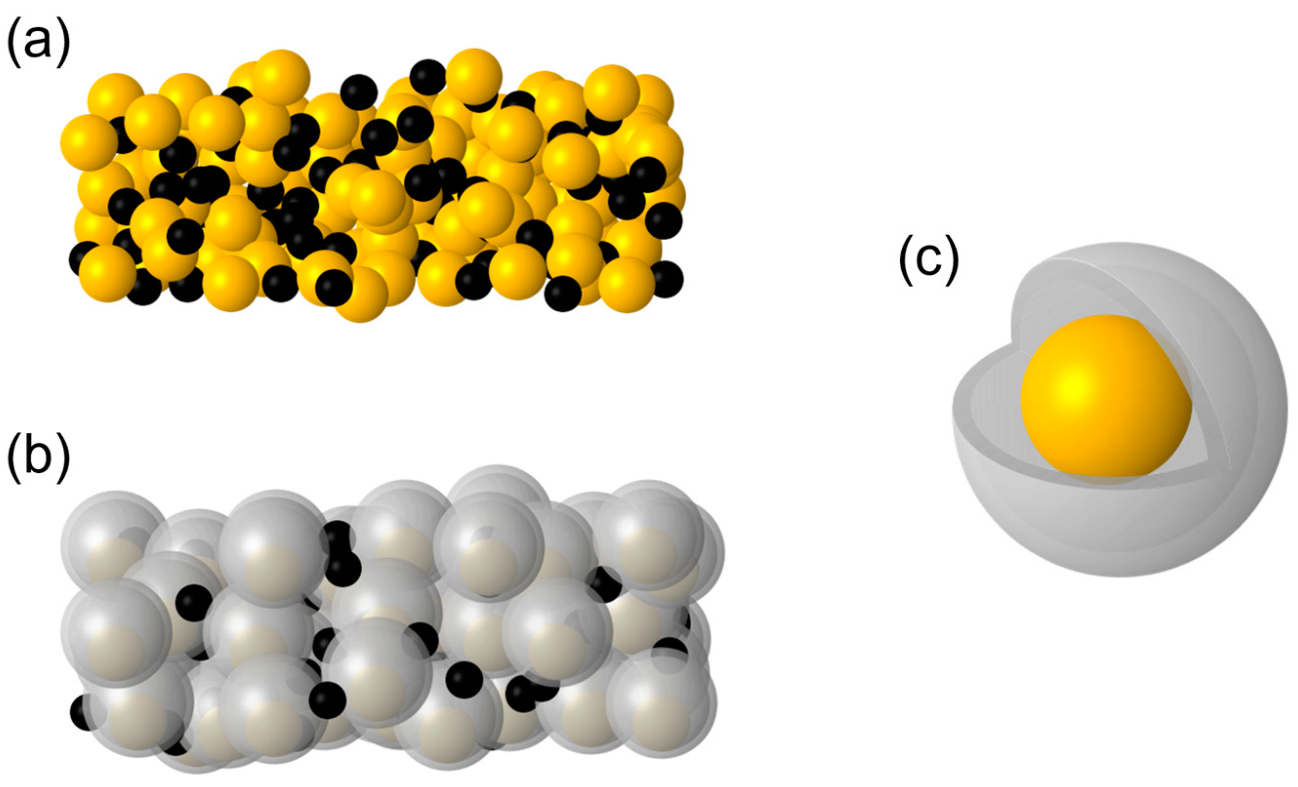
3.1. Synthesis of the Yolk-Shell Si@Void@C Particle

As shown in Figure 1, the yolk-shell Si@Void@C particle was synthesized via a four-step process. The void space between the SiNP and the C-shell was constructed using the template etching method.
The first step was to coat SiO2 on the surface of SiNPs. An amount of 50 mg of nano-sized SiNPs (Innochem) was employed. Then the SiNPs were dispersed in 250 mL of aqueous ethanol, where the volume ratio between ethanol and water stood at 4:1. This mixture underwent agitation for 5 min, followed by a 30 min sonication process. Subsequently, a solution containing 2.5 mL of concentrated ammonia (NH3·H2O, 28.0 wt%) and 500 mg of tetraethyl orthosilicate (TEOS, Innochem) was incrementally introduced into the previous mixed solution. The reaction was maintained at room temperature and an alkaline condition, with continuous stirring at a rate of 300 rad/min, for a duration exceeding 10 h. Within this timeframe, TEOS was hydrolyzed to generate SiO2, which homogeneously enveloped the SiNPs. In the subsequent process, the mixture was subjected to high-speed centrifugation (10,000 rad/min), followed by air drying at 70 °C. This procedure yielded purified Si@SiO2 nanoparticles. The volume ratio of Si to SiO2 in Si@SiO2 particles can be easily tuned by verifying the mass ratio of SiNPs to TEOS, typically set at 1:10. The hydrolysis reaction equation of TEOS under alkaline conditions is as follows:
( C 2 H 5 O ) 4 Si + 2 H 2 O = 4 C 2 H 5 OH + S i O 2
The second step was the oxidation of aniline (C6H7N) with ammonium peroxydisulfate ((NH4)2S2O8) in an acidic condition, which generated polyaniline (PANI) on the surface of Si@SiO2 [22,23,24]. C6H7N (465.65 mg, 0.005 mol, Aldrich) and (NH4)2S2O8 (1141 mg, 0.005 mol, Aldrich) were dissolved separately in 50 mL of HCl (1 M, Aldrich). Both resulting mixtures were ultrasonicated for 15 min. Then the Si@SiO2 from the previous step was added to the solution of C6H7N and stirred for over 5 min, followed by 30 min of ultrasonication. Then the solution of (NH4)2S2O8 was dropwise added to the solution of C6H7N under stirring in an ice bath for an hour. This mixture was stirred for 5 h under ice bath conditions, producing PANI coated on the SiNPs. PANI is considered as a potential electrode material among conductive polymers [25,26]. Finally, Si@SiO2@PANI was obtained by filtration, drying at 70 °C and grinding.
The third step was carbonizing the PANI layer to obtain the resulting Si@SiO2@C. The synthesized Si@SiO2@PANI composite was placed in an alumina crucible and loaded into a quartz tube within a tube furnace. Under an argon atmosphere, the temperature was ramped from ambient to 900 °C at 2 °C/min. Held at this temperature for 3 h, the precursor Si@SiO2@PANI underwent thorough carbonization, transforming to Si@SiO2@C. The carbonized PANI (C-PANI) was an amorphous hard carbon material with an irregular shape (Figures S1 and S2). In addition, C-PANI was also confirmed as a hierarchical mesoporous/microporous material by the BET method (Figure S3). These porous structures were beneficial to the transport of Li+. They served as a channel for hydrofluoric acid (HF) to enter the interior of the particles in the next step.
The fourth step was to etch the SiO2 layer. After being ground to powder, the Si@SiO2@C was dispersed within an HF solution (1 wt%) and agitated to prompt etching. The etching process was conducted for 45 min. After etching, the SiO2 layer was effectively removed. Finally, the yolk-shell Si@Void@C particles were obtained after drying. The void volume was approximately equal to the original SiO2 layer. Therefore, the final volume ratio of Si yolk to void (1:2.8~3.2 in this paper) in Si@Void@C can be determined by varying the mass ratio of SiNPs to TEOS.

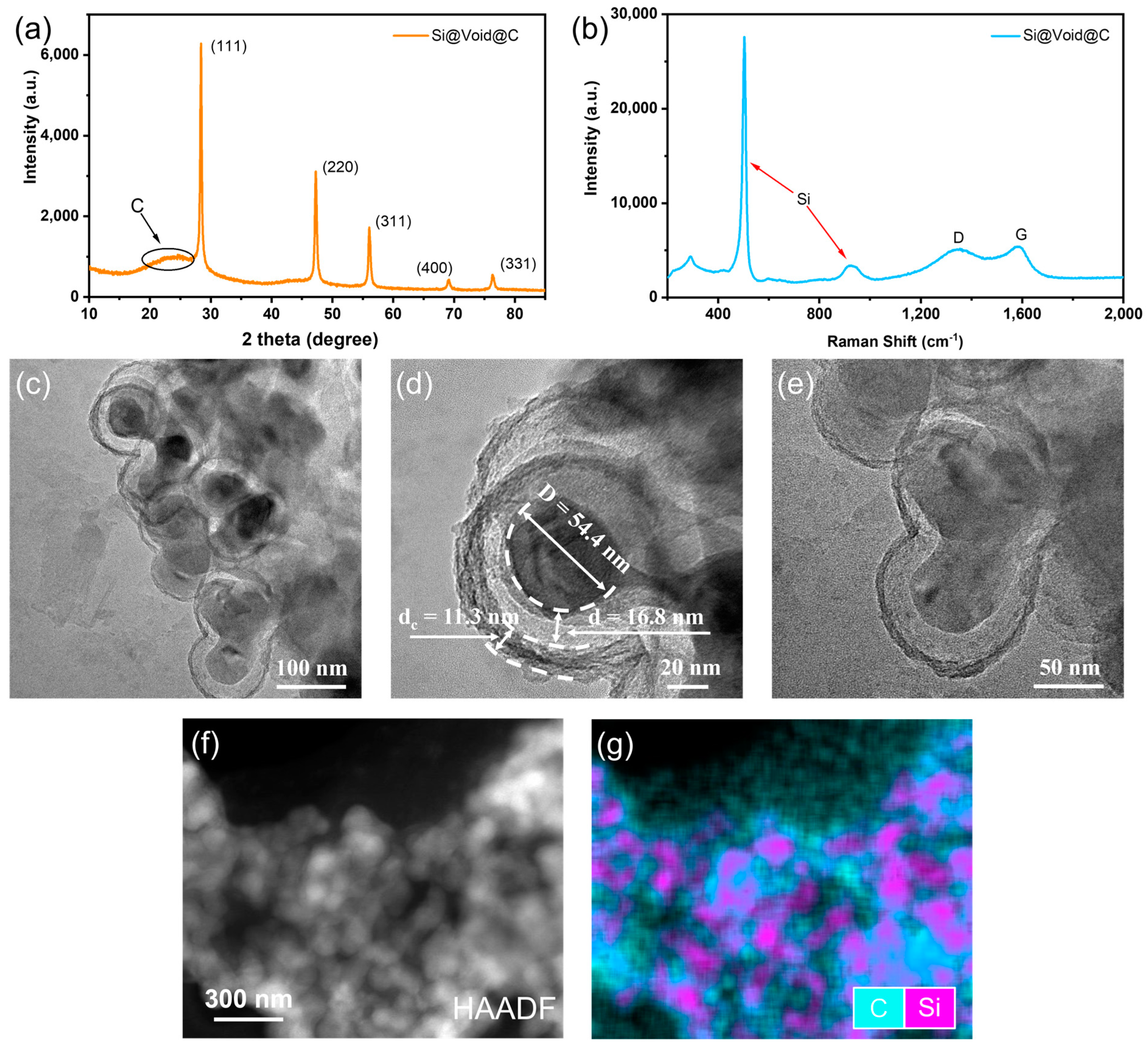
3.2. Yolk-Shell Structure of Si@Void@C

Figure 2a illustrates the XRD results of pristine SiNPs, revealing prominent peaks associated with the (111), (220), (311), (400), and (331) planes of crystalline silicon, which exhibits a spinel structure with space group Fd-3m (227). Si@SiO2 shows peaks identical to pristine SiNPs, indicating the preserved integrity of the Si yolks’ crystalline structure during SiO2 synthesis. Notably, Si@SiO2 exhibits a broad peak centered at ~23°, corresponding to amorphous SiO2. Additionally, a minute peak at 18.4°, attributed to the (101) plane of tetragonal SiO2 with space group P 4 ¯ n2, suggests the presence of a minute quantity of crystalline SiO2 in addition to the predominant amorphous SiO2.
Figure 2b shows a TEM image of Si@SiO2 particles, where Si yolks were encased within the SiO2 shell. As revealed by the HRTEM image in Figure 2c, the Si lattice plane (111) can be identified. Furthermore, a well-connected interface between the amorphous SiO2 phase and the crystal Si yolks is distinct. High-angle annular dark field STEM (HAADF-STEM) imaging and elemental mapping reveal that the distribution of Si and O elements are uniform (Figure 2d–f). These results indicate that SiO2 was evenly coated on Si yolks and consistent with the XRD result of Si@SiO2 (Figure 2a).
After HF etching, while a tiny peak of crystalline SiO2 persists, the overall XRD result of Si@SiO2 closely matches that of the pristine SiNPs (Figure 2a). It demonstrates that most SiO2 was removed while Si yolks maintained crystal properties. The above proves the feasibility of forming a specific volume of the void structure in this paper.
The XRD analysis of Si@Void@C in Figure 3a reveals distinct peaks corresponding to crystalline Si, while the broad peak center at ~23° was attributed to the (002) plane of amorphous carbon materials [27]. In the Raman spectrum of Si@Void@C (Figure 3b), a peak with a high intensity of 505 cm−1 and a weak intensity peak of 924 cm−1 are assigned to crystalline Si. Additionally, a peak of 1346 cm−1 and a peak of 1583 cm−1, respectively, known as the disorder-induced D-band and graphitic G-band of carbon, further confirm the amorphous carbon materials obtained by carbonization of PANI [28,29]. The XPS full survey spectrum of Si@Void@C (Figure S4a) shows peaks at ~104, 153, 285, 401, and 533 eV, which correspond to Si 2p, Si 2s, C 1s, N 1s, and O 1s, respectively [27]. The high-resolution Si 2p spectrum exhibits two peaks at 100.0 and 104.0 eV, corresponding to Si-Si and Si-O bonds, respectively (Figure S4b). The Si-O bond originates from trace residual SiO2. The high-resolution C 1s spectrum shows three peaks at 284.8 and 285.9 eV, attributed to C-C and C-N arising from C-PANI (Figure S4c) [30,31,32].
TEM images (Figure 3c–e) reveal that Si@Void@C particles possess a yolk-shell structure, with a noticeable void and the C-shell enveloping the Si yolk. Moreover, the HAADF-STEM image (Figure 3f) and the corresponding elemental mapping (Figure 3g) reveal the homogeneous distribution of C and Si elements. All of the above indicates that C-PANI was evenly wrapped on Si yolks, consistent with the XRD result of Si@Void@C (Figure 3a).
As depicted in Figure 3d, the Si yolk has a diameter of 54.4 nm. The void space and C-shell have 16 nm and 12 nm thicknesses, respectively. Thus, the Si@Void@C particles in our study possess diameters below 100 nm, falling below the resolution capabilities of scanning electron microscopy (SEM). This limitation obstructs us from employing SEM effectively to measure the mean diameter of the Si yolk and the average thickness of the void space across most particles. Additionally, TEM only permits localized observations of individual particles, hindering more broad characterization of the volume ratio distribution. Consequently, we can only assess the volume ratio of Si yolk to void space in a few Si@Void@C particles to extrapolate the corresponding volume ratio of most particles.
Figure 4 depicts two phenomenological models of Si@Void@C particles based on TEM results: one encompassing a single nucleus and the other involving two nuclei. Illustrated in Figure 4, D represents the diameter of the Si yolk, d corresponds to the thickness of the void space, and t denotes the thickness of the C-shell. By employing these two models, the Si yolk to void space volume ratio was calculated to be approximately 1:2.8~3.2. The basic formulas required for the calculation are as follows:
V sphere = 4 3 π R 3
V sc = 1 3 π h 2 ( 3 R 0 h )
Here, Vsphere refers to the volume of a standard sphere with a radius of R, and Vsc corresponds to the volume of a regular spherical crown with a height of h. R0 represents the radius of the sphere in which the spherical cap is located. By applying these two formulae presented above, we have determined that in the case of a single nucleus model, the volumetric ratio between the Si yolk and the surrounding void space amounts to 1:3.24. Meanwhile, in the scenario involving two nuclei, the volumetric ratio of a solo Si yolk to the void space stands at 1:2.83.

3.3. Electrochemical Performances of Si@Void@C Electrode

The schematic illustration of a conventional Si electrode is shown in Figure 5a. The expansion of Si particles during lithiation causes self-induced stress and adjacent particle compression, leading to particle fracture, electrode pulverization, and poor cycling performance. Furthermore, due to the expansion of Si particles, SEI undergoes continuous rupture and regeneration, filling gaps between particles.
In contrast, the Si yolk in the Si@Void@C electrode is encapsulated within a C-shell without direct contact with other particles (Figure 5b,c). The void provides ample space to tolerate the Si yolk expansion, avoiding the bursting of the C-shell and preventing electrode pulverization. Additionally, the SEI growth is confined within the C-shell. The carbonized PANI-based C-shell demonstrates high electronic conductivity, facilitating the formation of a robust conductive network and improving the cycling and rate performance of the Si@Void@C electrode.
To investigate the electrochemical performance of the Si@Void@C electrode and the impact of the void, we synthesized Si@C particles with the same structure as Si@Void@C particles but lacking the void space for comparison. We also synthesized Si@C and SiNP electrodes as control groups and conducted half-cell measurements using Li metal as the counter electrode.
Figure 6a,b presents the cyclic voltammetry (CV) curves of Si@C and Si@Void@C electrodes, respectively, at a scanning rate of 0.1 mV/s between 0.01 and 2.0 V vs. Li+/Li. Si@C exhibits two reduction peaks caused by SEI formation at 0.65 V and 0.93 V during the initial discharge process, which disappear in the subsequent cycles. The reduction peak of Si@C below 0.2 V is attributed to the formation of amorphous LixSi, while oxidation peaks at 0.36 V and 0.53 V relate to the dealloying of LixSi [31,33]. Si@Void@C shows a broad reduction peak around 0.56 V in the first cycle, corresponding to SEI formation. The positions and shapes of other oxidation and reduction peaks are similar to those of Si@C. However, the reduction peaks of Si@Void@C at 0.37 V and 0.54 V are more substantial, indicating that more active Li+ can be extracted from LixSi alloy, resulting in a higher reversible capacity. Figure 6c,d shows charge–discharge voltage profiles of Si@C and Si@Void@C electrodes, respectively, at the current density of 0.05 C (1 C = 1.72 mA/cm2) between 0.005 and 2 V. It was observed that compared to the Si@C electrode, the Si@Void@C electrode exhibited higher reversible capacity in the first 20 cycles, exceeding 700 mAh/g.
Figure 7a displays the rate performances of Si@C and Si@Void@C electrodes at different current densities. The charge capacities of the Si@Void@C electrode reach 768, 740, 656, 593, and 557 mAh/g at 0.05, 0.1, 0.2, 0.5, and 1 C, respectively, higher than those of the Si@C electrode. When the current density recovers to 0.1 C, the charge capacity can return to 737 mAh/g. Compared to Si@C, the Si@Void@C electrode demonstrates superior rate capacity, owing to the robust conductivity network of Si@Void@C during cycling. It highlights the beneficial effect of the void space in alleviating stress on the C-shell.
Figure 7b illustrates and compares the cycling performances of Si@C and Si@Void@C electrodes at 0.05 C. The reversible capacity of the Si@C electrode displays a rapid decay from the second cycle, with an average of 681 mAh/g for the first 20 cycles, dropping to only 150 mAh/g after 50 cycles. In contrast, the Si@Void@C electrode exhibits superior cycling performance, maintaining a stable reversible capacity of 754 mAh/g for the first 20 cycles and gradually decreasing to 424 mAh/g after 50 cycles. This comparison confirms that the combined void space and yolk-shell structures effectively alleviate stress caused by the expansion of Si yolk, preventing damage to the conductive network and avoiding electrode pulverization. Additionally, this design limits the growth of SEI, reducing the loss of reservable capacity and enhancing cycling performance.
By precisely controlling the volume ratio of Si yolk to the void space, the C-shell exhibits remarkable stability during lithiation and delithiation, preserving its structural integrity without notable expansion or extensive cracking. Consequently, the Si@Void@C particles remain complete and densely packed after multiple cycles. The Si@Void@C electrode retains its original structure integrity rather than disintegrating. During cycling, SEI forms exclusively on the surface of the SiNP within the C-shell, experiencing compression, stretch, and movement, exposing fresh SiNP surfaces and facilitating the repeated growth of SEI. Over time, the accumulated SEI gradually fills the void space within the C-shell, immobilizing the SiNPs at specific positions within the particle. Consequently, the overall structure transitions from Si@Void@C to Si@porous-SEI@C particles. Notably, the porous nature of the SEI allows for sufficient expansion and shrinkage of SiNPs, enabling successful lithiation and delithiation processes.
It is essential to highlight that characterizing Si@Void@C or Si@C particles within electrodes after cycling is challenging in our work. Before cycling, the prepared electrodes already contained many conductive additives (acetylene black), impeding TEM analysis of these particles. Techniques such as ultrasonication and freeze-drying are necessary to isolate these particles. However, these procedures could disrupt the C-shell of Si@Void@C, thereby hindering the validation of our conclusions. On the other hand, a cryo-focused ion beam scanning electron microscope (cryo FIB-SEM) can cross-section the electrodes after cycles, producing TEM lamella for corresponding analysis. Further, it could maintain the structural integrity of the C-shell except for certain sections. However, this preparatory procedure is intricate and pricey.

4. Conclusions

In conclusion, we have designed a yolk-shell nanostructured Si@Void@C anode material using a four-step template method. Si@SiO2, carbonized PANI, and Si@Void@C compositions have been comprehensively characterized and investigated. The void space, functioning as a buffer, accommodates expansion/shrinkage of the SiNPs during lithiation, preserving the structural integrity of the C-shell. A critical aspect of our innovation is precisely controlling the volume ratio between Si nanoparticles and the void space, ranging from 1:2.8 to 3.2. This design maximizes the volumetric energy density by accommodating the volume expansion of Si without excessive void space. Under such a structure, adverse effects, such as pulverization, isolation of Si-based anode material, and electrode disintegration, can be mitigated by trapping Si expansion and repeated rupture and reformation of the SEI within the C-shell. Consequently, the rate performance and cycling stability of the as-prepared Si-based anode has been enhanced. However, it is essential to acknowledge that the volume calculation in our work is idealized. Further experimental investigations are warranted to establish a more realistic understanding of the material structure and its electrochemical performance. Investigating the dynamics at the particle and electrode levels will further promote the rate performance and cycling stability of the Si-based anode material, facilitating the manufacturing of high-performance batteries.

Supplementary Materials

The following supporting information can be downloaded at: https://www.mdpi.com/article/10.3390/batteries9090446/s1, Figure S1, XRD result of carbonized polyaniline (C-PANI) in argon at 900 °C; Figure S2, TEM images of carbonized polyaniline(C-PANI) with (a) high and (b) low magnifications; Figure S3, (a) N2 adsorption–desorption curve and (b) pore size distribution of C-PANI; Figure S4, (a) XPS survey spectrum of Si@Void@C, high-resolution (b) Si 2p, (c) C 1s, and (d) N 1s XPS spectra of Si@Void@C; Figure S5, cycling performances of SiNP electrodes at 0.05 C with the corresponding coulombic efficiency.

Author Contributions

Conceptualization, X.Y. and G.Q.; methodology, X.Y. and W.K.; validation, W.K. and G.D.; investigation, X.Y., W.K., S.L., Y.T. and J.C.; resources, G.Q.; data curation, G.D., Y.T., J.C. and G.Q.; writing—original draft preparation, X.Y. and W.K.; writing—review and editing, G.D., S.L., X.L., R.T. and G.Q.; supervision, X.L., R.T. and G.Q.; project administration, R.T. and G.Q.; funding acquisition, G.Q. All authors have read and agreed to the published version of the manuscript.

Funding

This research was funded by the Shenzhen Science and Technology Program (Grant No. RCBS20200714114820077) and the Young Elite Scientists Sponsorship Program by CAST (2022QNRC001).

Data Availability Statement

The authors confirm that the data supporting the findings of this study are available within the article.

Conflicts of Interest

The authors declare no conflict of interest.

References

  1. Larcher, D.; Tarascon, J.-M. Towards Greener and More Sustainable Batteries for Electrical Energy Storage. Nat. Chem. 2015, 7, 19–29. [Google Scholar] [CrossRef] [PubMed]
  2. Dunn, B.; Kamath, H.; Tarascon, J.-M. Electrical Energy Storage for the Grid: A Battery of Choices. Science 2011, 334, 928–935. [Google Scholar] [CrossRef] [PubMed]
  3. Armand, M.; Tarascon, J.-M. Building Better Batteries. Nature 2008, 451, 652–657. [Google Scholar] [CrossRef] [PubMed]
  4. Pan, J.; Gong, M.; Cui, W.; Zheng, G.; Song, M. MOF-Derived Hetero-Zn/Co Hollow Core-Shell TMOs as Anode for Lithium-Ion Batteries. Coatings 2022, 12, 1487. [Google Scholar] [CrossRef]
  5. Li, H.; Li, H.; Lai, Y.; Yang, Z.; Yang, Q.; Liu, Y.; Zheng, Z.; Liu, Y.; Sun, Y.; Zhong, B.; et al. Revisiting the Preparation Progress of Nano-Structured Si Anodes toward Industrial Application from the Perspective of Cost and Scalability. Adv. Energy Mater. 2022, 12, 2102181. [Google Scholar] [CrossRef]
  6. Liu, Z.; Yu, Q.; Zhao, Y.; He, R.; Xu, M.; Feng, S.; Li, S.; Zhou, L.; Mai, L. Silicon Oxides: A Promising Family of Anode Materials for Lithium-Ion Batteries. Chem. Soc. Rev. 2019, 48, 285–309. [Google Scholar] [CrossRef]
  7. Choi, J.W.; Aurbach, D. Promise and Reality of Post-Lithium-Ion Batteries with High Energy Densities. Nat. Rev. Mater. 2016, 1, 16013. [Google Scholar] [CrossRef]
  8. Chan, C.K.; Peng, H.; Liu, G.; McIlwrath, K.; Zhang, X.F.; Huggins, R.A.; Cui, Y. High-Performance Lithium Battery Anodes Using Silicon Nanowires. Nat. Nanotech. 2008, 3, 31–35. [Google Scholar] [CrossRef]
  9. Tang, H.; Xu, Y.; Liu, L.; Zhao, D.; Zhang, Z.; Wu, Y.; Zhang, Y.; Liu, X.; Wang, Z. A Hollow Silicon Nanosphere/Carbon Nanotube Composite as an Anode Material for Lithium-Ion Batteries. Coatings 2022, 12, 1515. [Google Scholar] [CrossRef]
  10. Szczech, J.R.; Jin, S. Nanostructured Silicon for High Capacity Lithium Battery Anodes. Energy Environ. Sci. 2011, 4, 56–72. [Google Scholar] [CrossRef]
  11. Pan, K.; Zou, F.; Canova, M.; Zhu, Y.; Kim, J.-H. Systematic Electrochemical Characterizations of Si and SiO Anodes for High-Capacity Li-Ion Batteries. J. Power Sources 2019, 413, 20–28. [Google Scholar] [CrossRef]
  12. Liu, Y.; Shao, R.; Jiang, R.; Song, X.; Jin, Z.; Sun, L. A Review of Existing and Emerging Binders for Silicon Anodic Li-Ion Batteries. Nano Res. 2023, 16, 6736–6752. [Google Scholar] [CrossRef]
  13. Deng, L.; Zheng, Y.; Zheng, X.; Or, T.; Ma, Q.; Qian, L.; Deng, Y.; Yu, A.; Li, J.; Chen, Z. Design Criteria for Silicon-Based Anode Binders in Half and Full Cells. Adv. Energy Mater. 2022, 12, 2200850. [Google Scholar] [CrossRef]
  14. Wang, W.; Wang, Y.; Yuan, L.; You, C.; Wu, J.; Liu, L.; Ye, J.; Wu, Y.; Fu, L. Recent Advances in Modification Strategies of Silicon-Based Lithium-Ion Batteries. Nano Res. 2023, 16, 3781–3803. [Google Scholar] [CrossRef]
  15. Qian, Y.; Wang, H.; Li, X.; Song, T.; Pei, Y.; Liu, L.; Long, B.; Wu, X.; Wang, X. Sn-Doped BiOCl Nanosheet with Synergistic H+/Zn2+ Co-Insertion for “Rocking Chair” Zinc-Ion Battery. J. Energy Chem. 2023, 81, 623–632. [Google Scholar] [CrossRef]
  16. Park, J.-K. Principles and Applications of Lithium Secondary Batteries; John Wiley & Sons: Hoboken, NJ, USA, 2012; ISBN 978-3-527-65042-2. [Google Scholar]
  17. Wolfenstine, J. Critical Grain Size for Microcracking during Lithium Insertion. J. Power Sources 1999, 79, 111–113. [Google Scholar] [CrossRef]
  18. Liu, X.H.; Zhong, L.; Huang, S.; Mao, S.X.; Zhu, T.; Huang, J.Y. Size-Dependent Fracture of Silicon Nanoparticles During Lithiation. ACS Nano 2012, 6, 1522–1531. [Google Scholar] [CrossRef]
  19. Magasinski, A.; Dixon, P.; Hertzberg, B.; Kvit, A.; Ayala, J.; Yushin, G. High-Performance Lithium-Ion Anodes Using a Hierarchical Bottom-up Approach. Nat. Mater. 2010, 9, 353–358. [Google Scholar] [CrossRef]
  20. Wang, M.-S.; Wang, G.-L.; Wang, S.; Zhang, J.; Wang, J.; Zhong, W.; Tang, F.; Yang, Z.-L.; Zheng, J.; Li, X. In Situ Catalytic Growth 3D Multi-Layers Graphene Sheets Coated Nano-Silicon Anode for High Performance Lithium-Ion Batteries. Chem. Eng. J. 2019, 356, 895–903. [Google Scholar] [CrossRef]
  21. Zhang, L.; Wang, C.; Dou, Y.; Cheng, N.; Cui, D.; Du, Y.; Liu, P.; Al-Mamun, M.; Zhang, S.; Zhao, H. A Yolk–Shell Structured Silicon Anode with Superior Conductivity and High Tap Density for Full Lithium-Ion Batteries. Angew. Chem. Int. Ed. 2019, 58, 8824–8828. [Google Scholar] [CrossRef]
  22. Stejskal, J.; Sapurina, I.; Trchová, M. Polyaniline Nanostructures and the Role of Aniline Oligomers in Their Formation. Prog. Polym. Sci. 2010, 35, 1420–1481. [Google Scholar] [CrossRef]
  23. Kuzmany, H.; Sariciftci, N.S. In Situ Spectro-Electrochemical Studies of Polyaniline. Synth. Met. 1987, 18, 353–358. [Google Scholar] [CrossRef]
  24. Macdiarmid, A.G.; Chiang, J.C.; Richter, A.F.; Epstein, A.J. Polyaniline: A New Concept in Conducting Polymers. Synth. Met. 1987, 18, 285–290. [Google Scholar] [CrossRef]
  25. Chen, Y.; Xie, Y. Electrochemical Performance of Manganese Coordinated Polyaniline. Adv. Electron. Mater. 2019, 5, 1900816. [Google Scholar] [CrossRef]
  26. Molapo, K.M.; Ndangili, P.M.; Ajayi, R.F.; Mbambisa, G.; Mailu, S.M.; Njomo, N.; Masikini, M.; Baker, P.; Iwuoha, E.I. Electronics of Conjugated Polymers (I): Polyaniline. Int. J. Electrochem. Sci. 2012, 7, 11859–11875. [Google Scholar] [CrossRef]
  27. Lu, B.; Ma, B.; Deng, X.; Li, W.; Wu, Z.; Shu, H.; Wang, X. Cornlike Ordered Mesoporous Silicon Particles Modified by Nitrogen-Doped Carbon Layer for the Application of Li-Ion Battery. ACS Appl. Mater. Interfaces 2017, 9, 32829–32839. [Google Scholar] [CrossRef]
  28. Luo, W.; Wang, Y.; Chou, S.; Xu, Y.; Li, W.; Kong, B.; Dou, S.X.; Liu, H.K.; Yang, J. Critical Thickness of Phenolic Resin-Based Carbon Interfacial Layer for Improving Long Cycling Stability of Silicon Nanoparticle Anodes. Nano Energy 2016, 27, 255–264. [Google Scholar] [CrossRef]
  29. Pimenta, M.A.; Dresselhaus, G.; Dresselhaus, M.S.; Cançado, L.G.; Jorio, A.; Saito, R. Studying Disorder in Graphite-Based Systems by Raman Spectroscopy. Phys. Chem. Chem. Phys. 2007, 9, 1276–1290. [Google Scholar] [CrossRef]
  30. Chen, M.; Jiang, S.; Huang, C.; Wang, X.; Cai, S.; Xiang, K.; Zhang, Y.; Xue, J. Honeycomb-like Nitrogen and Sulfur Dual-Doped Hierarchical Porous Biomass-Derived Carbon for Lithium–Sulfur Batteries. ChemSusChem 2017, 10, 1803–1812. [Google Scholar] [CrossRef]
  31. Zhang, Y.-C.; You, Y.; Xin, S.; Yin, Y.-X.; Zhang, J.; Wang, P.; Zheng, X.; Cao, F.-F.; Guo, Y.-G. Rice Husk-Derived Hierarchical Silicon/Nitrogen-Doped Carbon/Carbon Nanotube Spheres as Low-Cost and High-Capacity Anodes for Lithium-Ion Batteries. Nano Energy 2016, 25, 120–127. [Google Scholar] [CrossRef]
  32. Shao, Y.; Jin, Z.; Li, J.; Meng, Y.; Huang, X. Evaluation of the Electrochemical and Expansion Performances of the Sn-Si/Graphite Composite Electrode for the Industrial Use. Energy Mater 2022, 2, 200004. [Google Scholar] [CrossRef]
  33. Key, B.; Morcrette, M.; Tarascon, J.-M.; Grey, C.P. Pair Distribution Function Analysis and Solid State NMR Studies of Silicon Electrodes for Lithium Ion Batteries: Understanding the (De)Lithiation Mechanisms. J. Am. Chem. Soc. 2011, 133, 503–512. [Google Scholar] [CrossRef] [PubMed]
Figure 1. Synthesis diagram of the yolk-shell Si@Void@C particle.
Batteries 09 00446 g001
Figure 2. Characterization of Si@SiO2. (a) XRD results of Si@SiO2, Si@SiO2 after HF etching, and pristine SiNPs, * represents a tiny peak attributed to the (101) plane of crystalline SiO2. (b) TEM and (c) HRTEM images of Si@SiO2. (d) HAADF-STEM image of Si@SiO2 before etching. Elemental mapping images of (e) Si and (f) O corresponding to (d) HAADF-STEM image.
Batteries 09 00446 g002
Figure 3. Characterization of yolk-shell Si@Void@C. (a) XRD result and (b) Raman spectrum of Si@Void@C. (ce) TEM images of Si@Void@C with different magnifications. (f) HAADF-STEM image of Si@Void@C. (g) Elemental mapping images of C and Si correspond to (f) HAADF-STEM image.
Batteries 09 00446 g003
Figure 4. The models of Si@Void@C (a) with single nuclei and (b) the other with two nuclei inside.
Batteries 09 00446 g004
Figure 5. Schematic illustrations of (a) a conventional Si electrode and (b) a Si@Void@C electrode. (c) Diagram of a Si@Void@C particle.
Batteries 09 00446 g005
Figure 6. Cyclic voltammetry curves of (a) Si@C and (b) Si@Void@C electrodes at 0.1 mV/s. Voltage profiles of (c) Si@C and (d) Si@Void@C electrodes at 0.05 C.
Batteries 09 00446 g006
Figure 7. (a) Rate performances of Si@C and Si@Void@C electrodes at different current densities. (b) Cycling performances of Si@C and Si@Void@C electrodes at 0.05 C with the corresponding coulombic efficiency.
Batteries 09 00446 g007
Disclaimer/Publisher’s Note: The statements, opinions and data contained in all publications are solely those of the individual author(s) and contributor(s) and not of MDPI and/or the editor(s). MDPI and/or the editor(s) disclaim responsibility for any injury to people or property resulting from any ideas, methods, instructions or products referred to in the content.

