Article

The Impact of Graphene in Na2FeP2O7/C/Reduced Graphene Oxide Composite Cathode for Sodium-Ion Batteries

Institute of Solid State Physics, University of Latvia, LV-1063 Riga, Latvia
*
Author to whom correspondence should be addressed.
Batteries 2023, 9(8), 406; https://doi.org/10.3390/batteries9080406
Submission received: 30 June 2023 / Revised: 20 July 2023 / Accepted: 1 August 2023 / Published: 3 August 2023
(This article belongs to the Special Issue Promising Carbon-Based Materials for Energy Storage)

Abstract

:
This study presents a thorough investigation of Na2FeP2O7 (NFP) cathode material for sodium-ion batteries and its composites with carbon and reduced graphene oxide (rGO). Our findings demonstrate that rGO sheets improve cycling performance in NFP/C/rGO composite in the absence of solid electrolyte interphase (SEI)-stabilizing additives. However, once SEI is stabilized with the help of fluoroethylene carbonate electrolyte additive, NFP with carbon additive (NFP/C) exhibits a superior electrochemical performance when compared to NFP/rGO and NFP/C/rGO composites. The decreases in capacity and rate capability are proportional to the amount of rGO added, and lead to an increase in overvoltage and internal resistance. Based on our results, we attribute this effect to worsened sodium kinetics in the bulk of the electrode—the larger ionic radius of Na+ hinders charge transfer in the presence of rGO, despite the likely improved electronic conductivity. These findings provide a compelling explanation for the observed trends in electrochemical performance and suggest that the use of rGO in Na-ion battery electrodes may present challenges associated with ionic transport along and through rGO sheets.

Graphical Abstract

1. Introduction

Sodium-ion batteries (SIBs) are a low-cost, safe and sustainable alternative for lithium-ion batteries (LIBs) that has over the years gained significant traction, especially when stationary, grid-level energy storage and low-cost alternatives to LIBs are concerned [1,2,3,4]. Moreover, the development of SIB cells has recently been included in the plans of at least one major battery manufacturer [5,6], with several other companies pursuing the production of SIBs [7]. These developments are largely due to the wider abundance of sodium vs. lithium (6th vs. 33rd most abundant element in the Earth’s crust) and the possibility to use cheaper aluminum foil as the anode current collector in SIBs [4,8]. Simultaneously, SIB material, battery cell and pack production processes are similar to those used for LIBs, allowing a relatively seamless transition to SIB production. While SIBs are potentially attractive LIB replacements, physicochemical differences and different material behaviors dictate that a detailed exploration and development of SIB materials is still needed [2].
Currently, several types of cathodes are being studied for SIBs. These include layered transition metal oxides (most commonly P2 and O3 types), polyanionic compounds, such as phosphates, pyrophosphates, NASICON-type materials, sulfates and organic compounds, as well as Prussian blue with its analogues [4]. Na2FeP2O7 was first reported by Honma et al. [9]; it has a theoretical gravimetric capacity of 97 mAh/g, almost all of which can be obtained practically [10,11,12]. While several other cathode material classes possess higher theoretical and practical capacities (Prussian blue and layered sodium–transition metal oxides yield practical capacities of up to 157 and 190 mAh/g, respectively [13,14,15,16]), Na2FeP2O7 is highly stable and does not pose the danger of toxic decomposition by-products or oxygen evolution. Moreover, Na2FeP2O7 possesses an excellent cycle life [10,17,18,19,20,21,22,23,24] and no capacity decrease has been observed over the first 500 full charge/discharge cycles [11]—a significant advantage over many of the available cathode alternatives, including polyanionic compounds. A similarly high cycling stability is also observed for analogous LIB cathode materials [25,26].
The further optimization of the capacity and rate capability of Na2FeP2O7 remains a challenge for which electrode formulations, interfaces and electrolyte formulations can be tailored [27]. The use of electron-conducting additives has become a common practice for battery electrodes [28,29]. Among these, carbon-based materials are the most popular. Moreover, carbon additives not only improve the general conductivity of the electrodes, but can also reduce the grain growth and nucleation if added during the synthesis of the active material [30,31,32], and can have meaningful effects on the electrode-electrolyte interface [33,34]. The grain-size reducing effects of carbon have indeed been so distinct that the grain size reduction might be the main mechanism behind the improved electrochemical performance of some electrode materials [32].
Graphene—a single layer of carbon atoms ordered within a honeycomb lattice pattern [35,36]—has been extensively studied as an additive for LIB cathodes [36]. Due to a relatively easier preparation of the material itself [37], as well as its composites, graphene oxide (GO) is often used as a starting material, followed by a subsequent reduction step. GO is an imperfect graphene sheet that is decorated by hydroxyl, epoxy and some carbonyl functional groups, some of which are still present as the graphene oxide is reduced and reduced graphene oxide (rGO) is formed [38]. rGO can homogenously mix with the grains, wrap individual particles and forming other composite structures [39].
The ability of rGO to boost the electrochemical performance of electrodes has successfully been demonstrated in both LIBs [36,40,41,42,43] and SIBs [44,45,46,47]. The benefits typically occur due to the rGO forming a percolating or partially percolating electron-conducting network, and hence improving the general electron transport in the electrode [48]. Interestingly, while the addition of rGO often provides an improved electrochemical performance over reference samples, similar improvements in electrochemical performance have been attained with the use of other additives or processing [11,49,50]. Furthermore, it has been shown that gasses, liquids and ions cannot migrate through graphene [51,52], raising questions about its impact on the overall ionic conductivity of the electrolyte-filled porous electrodes. While lithium ions can permeate through disordered graphene [51], the 29% larger size of Na+ is likely to impede such transport. Therefore, even though all but a few studies [48] have shown rGO to be a very promising conducting additive to cathodes for LIBs, the ability of rGO to improve the electrochemical properties of SIB cathodes is not obvious.
In this work, we prepare Na2FeP2O7/C/rGO composite cathodes and analyze their electrochemical properties as a function of rGO content. By systematically analyzing the rate capability and cycling stability of Na2FeP2O7 composites with rGO in electrolytes with and without fluoroethylene carbonate (FEC)—a solid electrolyte interface (SEI) stabilizing compound—we demonstrate the benefits and potential shortcomings of the rGO additive in Na2FeP2O7/C/rGO electrodes for SIBs.

2. Materials and Methods

Na2FeP2O7 (NFP) was synthesized using an already described method [11] via a three-step process, also shown schematically in Figure 1. Na2CO3, NH4H2PO4 and FeC2O4·2H2O were dissolved in deionized water. The mixture of chemicals was supplemented by glucose and/or suspension of graphene oxide in water (concentration 1.5 wt.%, BGT Materials, sheet size 1–20 μm) in some cases to form carbon additive (Na2FeP2O7/C), composite with rGO (Na2FeP2O7/rGO) or a composite of all three materials (Na2FeP2O7/C/rGO). The amount of glucose added attributed to 4.8 wt.% of carbon in the final composite as determined by combustion analysis in our previous work [11], and was always kept constant. This amount of carbon in the sample showed superior electrochemical properties for NFP. The amount of graphene oxide added to the synthesis was adjusted to constitute 0.5–2.5 wt.% of the final product. Based on the current literature, we expect only a minor reduction in the mass of the resulting rGO when compared to GO [53]. The solution was heated for 24 h at 60 °C to evaporate the water. The substance was then dried in a vacuum oven at 80 °C for 3 h. Subsequently, the precursor was ground and heated for 3 h at 350 °C in Ar + 5% H2 flow. After that, the powder was ground again, pelletized and heated for 6 h at 600 °C in Ar + 5% H2. In the further text, we abbreviate Na2FeP2O7 with NFP. The composites are consequentially denoted as NFP/C, NFP/rGO and NFP/C/rGO.
To analyze the purity of the obtained powder, X-ray diffraction (XRD) analysis was carried out using MiniFlex600 X-ray diffractometer (Rigaku Corporation, Tokyo, Japan). Rietveld refinement was performed with Profex software, version 5.2.2 [54]. Raman spectrometry was employed to study carbon D and G bands, using Raman Spectrometer TriVista CRS Confocal TR777 (S&I Spectroscopy & Imaging GmbH, Warstein, Germany), wavelength λ = 532 nm. Scanning electron microscopy (SEM) analysis was performed using Helios 5 UX microscope (Thermo Fischer Scientific, Waltham, MA, USA) for powders and fresh and cycled electrodes. The cycled electrodes were taken out of separator-less cells (electrodes are placed in electrolyte solution and held in place by stainless steel clamps) in Ar-filled glovebox, rinsed in diethyl carbonate for 4 min and left to dry thereafter. X-ray photoelectron spectroscopy (XPS) analysis was performed for pristine powders and the same fresh and cycled electrodes by using monochromatic Al Kα X-ray source by using Thermo Fisher ESCALAB Xi+ (Thermo Fischer Scientific, Waltham, MA, USA). Binding energy scale was calibrated with freshly etched metallic copper to result in a binding energy of 932.6 eV for Cu 2p3/2 line. For the recording of the spectra, X-ray beam size of 650 × 10 μm, pass energy of 20 eV and step size 0.1 eV were used.
Electrodes were prepared by mixing the synthesized product, carbon black and polyvinylidene fluoride (PVDF) (mass ratio 75:15:10) in n-methyl-2-pyrrolidone (NMP) solution. Obtained slurry was coated on Al foil by a doctor blade. Electrodes were dried for 24 h at 80 °C in vacuum oven and then transferred to argon-filled glovebox. The diameter of the obtained electrodes was 10.0 mm, with an average loading of 1.4 mg/cm2 (0.136 mAh/cm2). Electrochemical cells were assembled by using glass microfiber separator Whatman GF/B (Cytiva, Washington, DC, USA) and metallic sodium as counter electrode. An amount of 1 M NaClO4 solution in propylene carbonate (PC) with or without 5 wt.% fluoroethylene carbonate (FEC) additive was used as electrolyte. Electrochemical measurements were carried out using multichannel potentiostat/galvanostat BioLogic VMP3 (BioLogic, Grenoble, France). Galvanostatic charge–discharge curves were obtained in the voltage range 2.0–4.0 V; capacity was calculated by using the total mass of the composite. Electrochemical impedance spectroscopy measurements were performed 24 h after assembling the electrochemical cells and at least 6 h after cycling in a frequency range from 100 kHz to 0.01 Hz with a 10 mV amplitude of the alternating voltage.

3. Results

3.1. Structure, Composition and Morphology

XRD analysis was performed to determine the purity of the obtained material (Figure 2a). The results confirm that Na2FeP2O7 (NFP), ICDD no. 96–400-1803, with no crystalline impurities was obtained during the synthesis, as the diffractogram shows all peaks corresponding to the NFP and its triclinic framework with P-1 symmetry, initially reported by Barpanda et al. [20]. The results of Rietveld refinement are shown in Supplementary Materials, Figure S1 and Table S1, and are relatively similar for all carbon-containing NFP samples. The average lattice values are a = 6.43 Å, b = 9.42 Å, c = 11.02 Å, α = 64.48°, β = 85.72°, γ = 72.89° and are in good agreement with Barpanda et al. [20]. The fitting parameter values are Rp = 1.59%, Rwp = 2.21%, Rexp = 1.17%, χ2 = 3.89.
Results of the XPS survey (Figure 2b) of NFP/C/rGO (2.5 wt.% rGO) powder indicate the presence of all relevant elements and a small additional peak of nitrogen likely bound to the carbon structures in the sample.
We observe a more pronounced D-band in the NFP/rGO composite corresponding to disordered carbon, while the intensity of G band is higher in NFP/C, indicating a larger proportion of graphitic carbon (Figure 2c). Both D and G bands are also wider in samples containing the carbon additive. NFP/C/rGO composites display a growing relative intensity of D band with increasing rGO content. Note that typically, D band, located at about 1350 cm−1, corresponds to disorder in the A1g breathing mode of the six-fold aromatic ring of the carbon and defects of the sp2 domains (i.e., disordered carbon structures), while G band at about 1595 cm−1 can be assigned to E2g phonon in the hexagonal structure of the sp2-hybridized carbon atoms and is typical to graphite [55,56]. For an additional analysis of the GO and rGO used in this work, the reader can refer to one of our group’s prior studies [57].
In general, the high intensity of D band in NFP/rGO indicates a high content of disordered carbon structures that the thermal reduction process is not able to mitigate. The 600 °C temperature of synthesis is relatively inflexible, as the crystalline form of NFP starts forming only slightly below 600 °C [58], and impurities appear in the obtained material if the temperature of the final step of the synthesis is increased to 650 °C [11]. Nevertheless, a partial reduction of GO with the removal of carboxyl and other groups has been demonstrated already at temperatures significantly below 600 °C elsewhere [59,60].
The XPS analysis of pristine GO displays prominent peaks at 284.5 eV (C–C), 286.5 eV (C–O) and 287.6 eV (C=O), as well as a π–π* satellite peak at higher binding energies. The annealing of the powder at 600 °C in Ar + 5% H2 atmosphere shrinks the C–O peak and virtually eliminates the C=O peaks, leaving the C–C peak at 284.4 eV to be the most pronounced as indeed expected for rGO [61,62]. This indicates that the reduction of GO has taken place, removing most of the functional groups bound to the carbon lattice. The XPS spectra of Na2FeP2O7/rGO display peaks at 284.0 and 285.0 eV, corresponding to sp2- and sp3-hybridized carbon, respectively. The peak at 284.0 eV is likely observed due to the presence of rGO, while the maximum at 285.0 eV resulted from trace carbon left in the sample from Na2CO3 or FeC2O4 that were used in the synthesis. A 286.3 eV peak (C–O) and a peak at 289.1 eV (O–C=O) are observed both here and in our previous work [11], and are likely stemming from surface carbon compounds and trace Na2CO3 left on the surface due to H+–Na+ exchange in air, respectively. The C 1s peak of sp3 carbon is more intense for Na2FeP2O7/C at 284.9 eV, while the C 1s spectrum of NFP/C/rGO is very similar to NFP/C due to the carbon additive comprising a significantly larger percentage than rGO in the obtained composite (4.8 wt.% vs. 2.5 wt.%).
The SEM images of the pristine NFP (Figure 3a) indicate a particle size of up to 5 μm. NFP/C composite (Figure 3d) shows a more fragmented surface and smaller particle size, as the carbon additive limits the particle growth. In the NFP/rGO (2.5 wt.%) composite (Figure 3b,c) sheets of rGO are clearly visible and cover a part of the active material, while the grain size is a mix between finer particles and several μm large particles observed for pristine NFP. In general, in rGO composites, some of the rGO sheets are mixed with the NFP as shown for the NFP/C/rGO (2.5 wt.%) composite in Figure 3e. The observed rGO sheets often display crumpled features and some of the sheets are stacks of several rGO layers. The grain size of NFP/C/rGO (Figure 3e,f) is comparable to NFP/C.

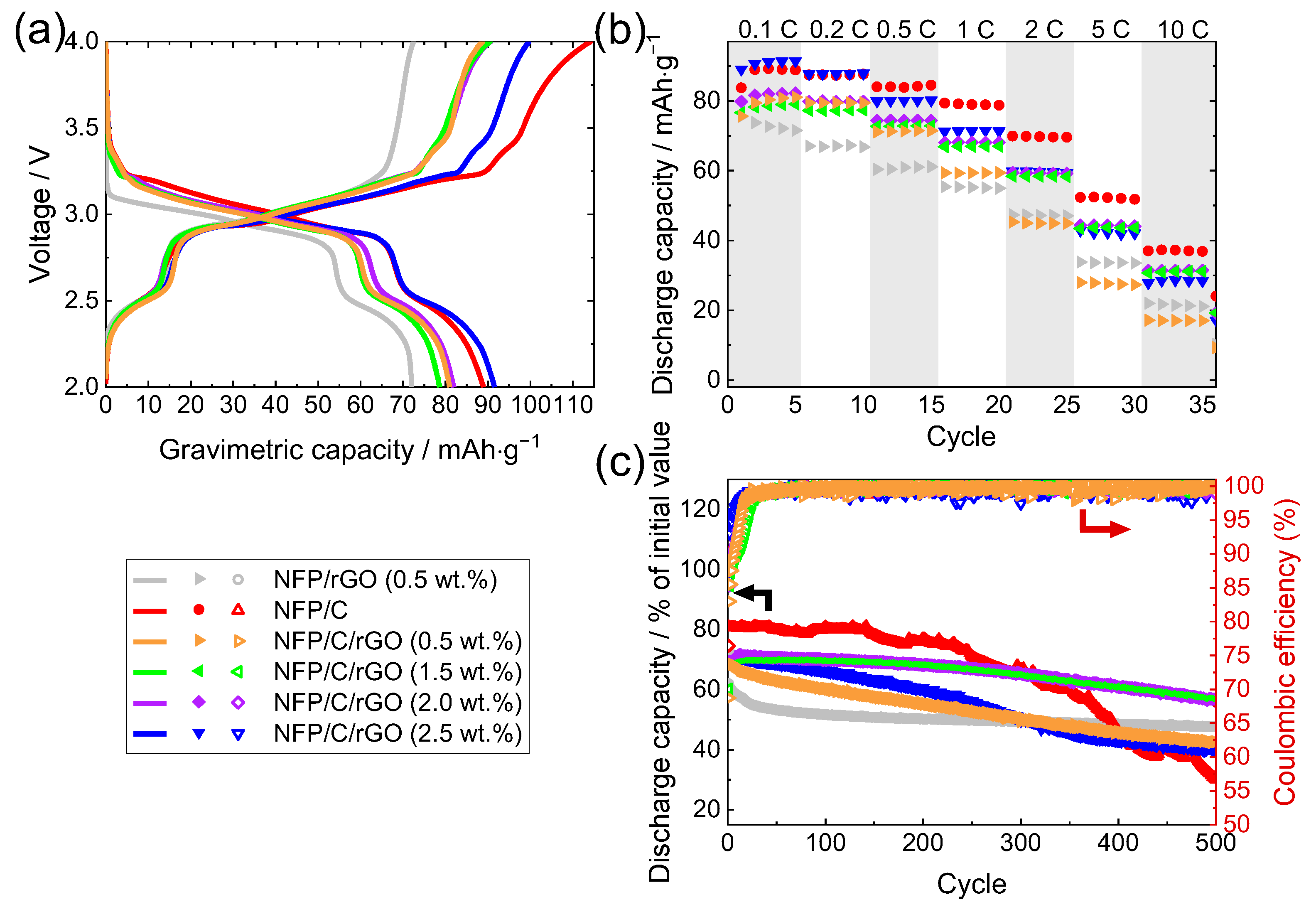
3.2. Electrochemical Measurements

We first examine cells with the FEC-free 1 M NaClO4 solution in PC used as electrolyte. Initial experiments on electrode materials of SIBs often did not include any SEI stabilizing additives in the electrolyte and typically involved NaClO4 or LiPF6 salts dissolved in organic solvents [10,17,63,64,65,66,67]. Large discrepancies between charge and discharge capacities were observed both in the prior works and here (Figure 4). These can be explained with parasitic reactions unrelated to Na insertion in the active electrode materials—more specifically, the decomposition of PVDF binder [68,69,70] and the decomposition of the electrolyte at the anode [71,72,73].
Figure 4 shows the obtained data for samples with different amounts of rGO and glucose. Data from pristine NFP were not included, because the charge capacity, as well as rate capability and cyclability, were extremely low; see reference [11] for details. For the sample containing only rGO (0.5% wt.%), initial charge capacity (~70 mAh/g) and rate capability are lower than for samples containing additional glucose as a carbon source. The electrochemical performance is nevertheless improved when comparing to the pristine material. By adding glucose as a carbon source (4.8 wt.%, optimized in our prior work [11]), a discharge capacity up to 89 mAh/g is measured (sample NFP/C in Figure 4). Despite a larger total carbon content, most NFP/C/rGO composites display a lower capacity than NFP/C. An exception is NFP/C/rGO sample with 2.5 wt.% rGO, for which the capacity is comparable to that of NFP/C, albeit the composite has a lower rate capability. The highest discharge capacities after 500 cycles at 1 C are obtained in the case of NFP/C/rGO composites with 1.5 wt.% and 2.0 wt.% rGO–69 mAh/g or 92% of the initial value.
As the cycling stability depends as much on the electrolyte as it does on electrodes, next, we measure the electrochemical performance of the obtained materials in 1 M NaClO4 electrolyte with 5 wt.% FEC (Figure 5). SEI stabilizing electrolyte additives (especially fluoroethylene carbonate—FEC) form a stable NaF-containing electrode–electrolyte interface that limits the decomposition of electrolyte and the defluorination of PVDF binder [74,75].
With FEC additive introduced in the electrolyte, the measured rate capabilities and long-term cycling stabilities of all materials are significantly improved. This ensures a stable cell with a near 100% Coulombic efficiency in which the measured charge and discharge capacities are aligned, as the side reactions are minimized. Surprisingly, although the electrochemical performance of all measured Na2FeP2O7 (NFP) compounds has improved with the addition of C or rGO over the pristine material (Figure 5), the best discharge capacity and rate capability is again displayed by NFP/C and not NFP/C/rGO (Figure 5b). The improvement in rate capability is best visible at 1 C and above, as approximately 40 mAh·g−1 of specific capacity is still retained even at a 20 C rate. The gravimetric charge capacity is higher for NFP/C even at a 0.1 C rate, reaching 92 mAh/g. The results show that carbon additive alone is enough to improve the electrochemical performance of NFP cathode, and the presence of rGO does not provide further benefits in this case.
By systematically adjusting the content of rGO from 0.5 to 2.5 wt.% while maintaining the amount of carbon additive constant at 4.8 wt.%, we see that the capacity and rate capability decrease with an increasing amount of rGO (Figure 6). This is a distinct trend that is most clearly visible in cells with the FEC-containing electrolyte (Figure 6a). While the same might be true for the cell with FEC-free electrolyte (Figure 6b), we observed a larger variability in measurements, by all accounts a consequence of factors beyond the cathode (e.g., surface of sodium counter electrode, slight differences in mechanical pressure between the electrodes and the amount of electrolyte).
The long-term cycling stability at 1 C was excellent for all studied composite NFP electrodes. The composites display virtually no capacity loss during the first 500 cycles at a 1 C rate regardless of the presence of rGO.

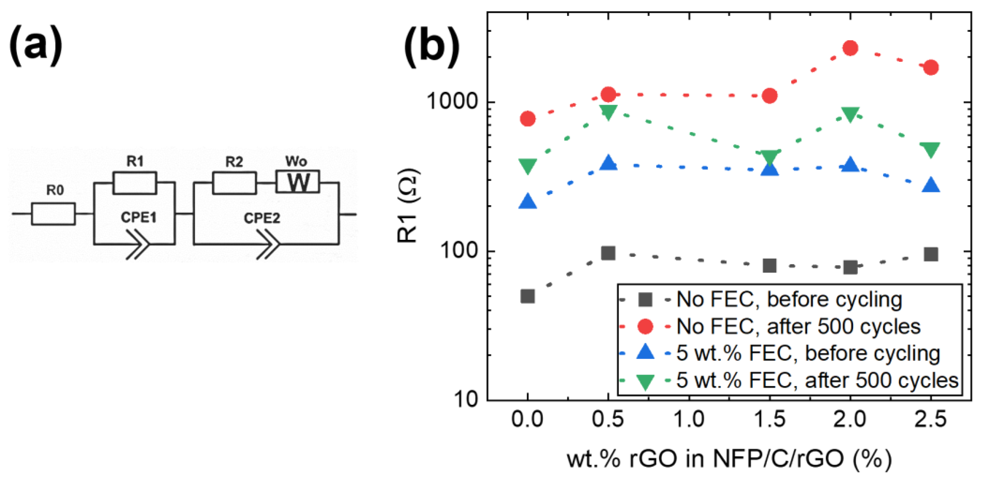
3.3. Electrochemical Impedance Spectroscopy

Upon a closer inspection of the charge–discharge voltage profiles in Figure 5a, we see that the overvoltage is the lowest for the rGO-free NFP/C composite and highest for NFP/rGO (0.5 wt.%), which does not contain any carbon additives. The values of overvoltage of NFP/C/rGO are located between those of NFP/rGO and NFP/C. While the overvoltage values for all NFP/C/rGO samples are very similar, the small variations follow the concentration of rGO.
As the overvoltage is proportional to cell resistance, we investigate the internal resistances of the electrochemical cell by using electrochemical impedance spectroscopy (EIS) (Figure 7). All but a few EIS spectra show two semicircles, which were fitted with an equivalent circuit shown in Figure 8a. These are typically attributed to charge transfer resistance Rct (low-frequency semicircle) and solid electrolyte interphase resistance RSEI [76] or contact resistance between the current collector and working electrode [77,78] (high-frequency semicircle). Lately, several very thorough studies have shown the high frequency arc to correspond to interface between the working electrode and current collector [79,80], including our previous investigation on NFP [81], where we demonstrated that the resistance is invariant to particle size (i.e., expected surface area of the active material) or electrode thickness and, the same as herein, has a capacitance on the order of 10−5 F, which is in line with the expected electric double-layer capacitance for the ≈0.8 cm2 area of the current collector, whereas the value would be extremely low if calculated for the active area of the electrode material.
We analyze the resistance R1, which we attribute to contact resistance between the current collector and cathode, in detail, in Figure 8b. While there is some difference from sample to sample as evident from individual EIS spectrum in Figure 7, no certain trend can be discerned as a function of rGO content. Instead, the differences could at least in part be explained with the variance in assembly of the coin cells as somewhat usual [82,83,84]. In all cases, the NFP/C sample has lower R1 values than NFP/C/rGO. This might mean an improved contact between NFP/C and the current collector.
When comparing the resistance values R1 of the high frequency arc, we see a significant jump in R1 after 500 cycles in the FEC-free electrolyte, while the increase in R1 after 500 cycles in electrolyte with FEC is more modest. While it might speak in favor of R1 being SEI resistance, we also indicate that PVDF has been shown to decompose in FEC-free electrolytes [68,69,70] and can affect the electrode–current collector contact. Surface accumulation of fluorine in cycled electrodes is observed in the XPS depth profiles discussed later in the text, supporting this argument. Thus, the increase in R1 can most likely be attributed to the loss of contact between the current collector and active material.
The low frequency resistance R2 has often been attributed to charge transfer resistance or, at times, to ionic resistance in the pores of the cathode [81,85]. We do not observe a clear variation of R2 as a function of rGO content. However, R2 varies significantly depending on the electrolyte composition (see the low frequency semicircles in Figure 7a,c).

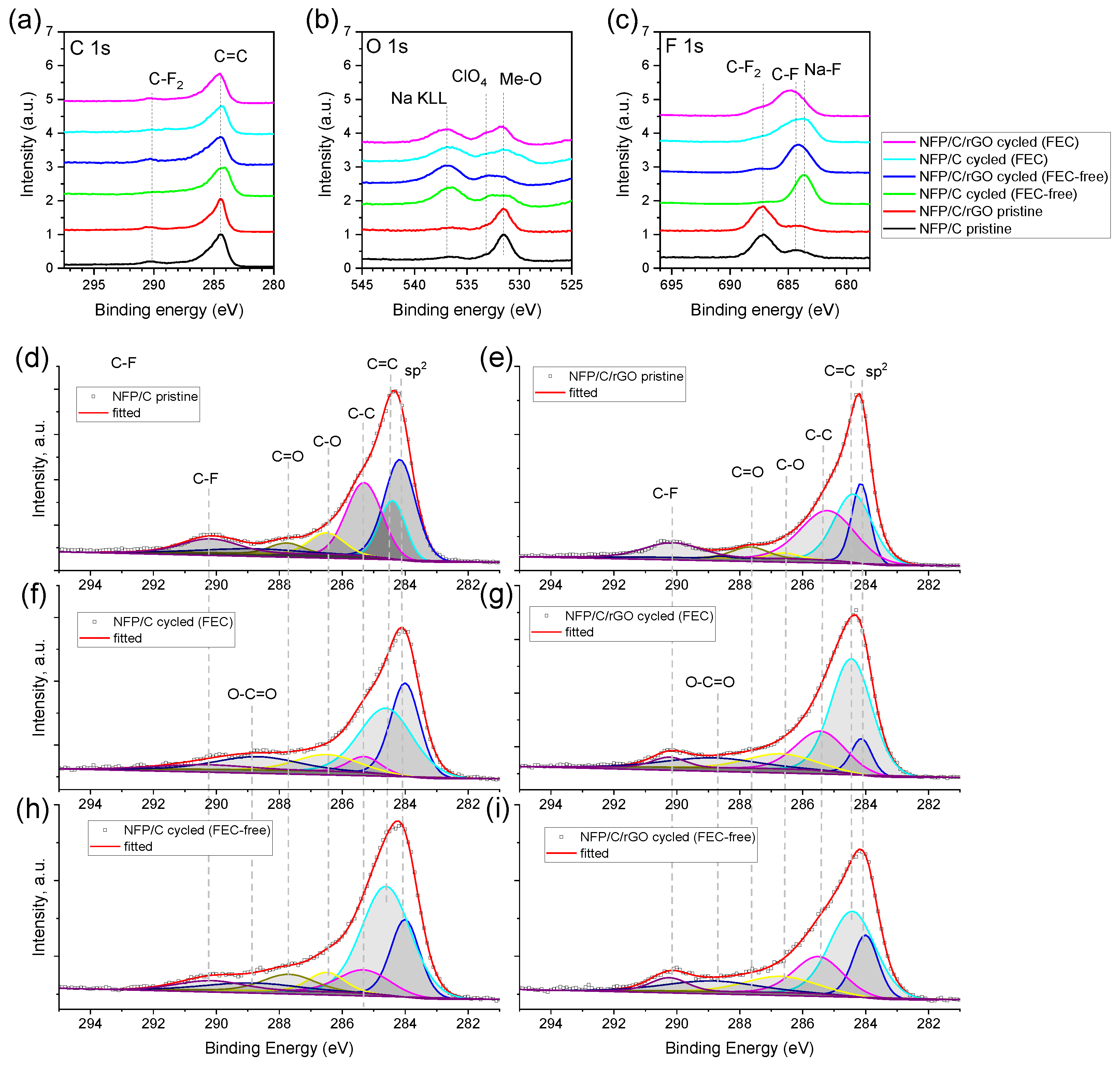
3.4. Post-Mortem Analysis

To further investigate the ageing behavior of the electrodes, fresh and cycled NFP/C and NFP/C/rGO electrodes are inspected by using SEM and XPS. Figure 9 contains SEM images of both fresh and cycled electrodes (500 cycles at 1 C). The formation of a solid electrolyte interface (SEI) on the electrode surface is observed in all cycled electrodes, irrespective of the type of electrolyte used or the presence of reduced graphene oxide (rGO). Figure 9b,c,e,f clearly demonstrate the SEI formation, as the electrode features have become less defined.
The XPS measurements on C 1s, O1s and F 1s are shown in Figure 10; additional XPS spectra of Na 1s, Fe 1s and P 1s are made available in the Supplementary Figure S2. The measured XPS spectra do not indicate significant differences between the fresh NFP/C and NFP/C/rGO samples. Carbon spectra (Figure 10a) are dominated by a peak at 284.4 eV, corresponding to C=C bonding in carbon black. A long tail toward higher energies corresponds to a combination of different other carbon-related bondings in carbon black, binders, rGO additive and active material. Fitted C 1s XPS spectra are shown in Figure 10d–i; the placement of the peaks are in line with the peaks for sp2 carbon (284.15 eV), C=C bonding (284.5 eV), C–C bonding (285.4 eV), C–O bonding (286.6 eV), C=O bonding (287.8 eV) and O–C=O bonding (carbonates, 288.8 eV [86]). Given the large amount of fitted peaks, without further investigation, the precise determination of phase proportions is deemed to be ambiguous at best; however, the results provide a good insight into the complexity of the carbon bonding in the pristine and cycled electrodes. As the quantity of rGO is very small in comparison with carbon black conducting additive, the similarity of the C 1s spectra in NFP/C and NFP/C/rGO is to be expected. The small peak at 290.6 eV is typically associated with CF2 bonding in PVDF.
The O and F spectra of the cycled samples change significantly (Figure 10b,c). For all electrode compositions, the relative intensity of oxygen 531.5 eV peak corresponding to Na2FeP2O7 decreases, as the growth of SEI takes place. The low intensity peaks at 533 eV correspond to residual perchlorate (ClO4), while the adjacent peak at 537 eV is an Auger peak of Na KLL. The shape of the O 1s peak suggests additional contributions from other components, such as Na2CO3, alkylcarbonate and polyethylene oxides (PEO) (~532.8 eV, ~533–534 eV and ~533 eV, respectively [87]) known to be prominent in the SEI.
The peak in F 1s spectra at 687.5 eV associated with C–F2 bonding is noticeably prominent in the fresh, uncycled electrodes. However, after 500 cycles, this peak becomes significantly less distinguishable, while a distinct peak at 683.6 eV (Na–F) emerges, indicating the growth of the SEI. The composition of the SEI varies depending on the presence of FEC in the electrolyte, namely, cycling in an FEC-containing electrolyte leads to the emergence of an additional peak at 685 eV, which can be attributed to C–F bonding. Interestingly, the Na–F peak at 683.6 eV is visible even for samples cycled in FEC-free electrolytes where the only source of fluorine is PVDF. Thus, similarly to the work of Villevieille et al. [68], we conclude that a defluorination of PVDF takes place. rGO sheets are known to promote the structural integrity of electrodes. Consequently, as PVDF decomposes, the enhanced cycle life of electrodes containing rGO can be explained.

4. Discussion

We investigated Na2FeP2O7 (NFP) and its composites with carbon (NFP/C) and reduced graphene oxide (NFP/rGO and NFP/C/rGO) and found that NFP/C shows a superior electrochemical performance compared to NFP/rGO and NFP/C/rGO composites. Discharge capacity of up to 92 mAh/g is measured for NFP/C composite (up to 44 mAh/g can still be extracted at 20 C). The addition of rGO resulted in a reduced capacity (76–88 mAh/g) and rate capability, which were proportional to the amount of rGO present. Moreover, we observed an increase in overvoltage (polarization) and internal resistance (contact resistance and charge transfer resistance in EIS) upon the addition of rGO. While Prussian blue [13,14] or layered sodium–transition metal oxides [15,16] and some phosphate materials [88,89] yield higher discharge capacities (practical capacities of up to 157, 190 and 142 mAh/g, respectively [90]), the cycle life of NFP/C and NFP/C/rGO composites stands out as excellent in comparison with the alternatives. No capacity loss is observed over the first 500 cycles.
It has been shown that different types of materials (and carbons in particular) can lead to different SEI growths in insertion batteries [34]; thus, it was important to investigate the differences between the composite electrodes thoroughly. We found, however, that the presence of rGO does not significantly alter the electrode morphology of the fresh and cycled electrodes. Furthermore, the SEI composition is very similar for NFP/C and NFP/C/rGO electrodes.
With the surface chemistry and morphology being very similar, we conclude that the systematically worse electrochemical performance of NFP/C/rGO composites is due to slower sodium kinetics in the bulk of the electrode. In short, the effect of rGO sheets impeding sodium transport is felt more than the improvement in electron transport. To elaborate, a proper functioning of the cathode is ensured by the efficient transfer of sodium within and beyond the electrode. While Na+ and e travel simultaneously within the solid active material (Na2FeP2O7), once Na ions are extracted from the active material, they must be transferred to the counter electrode via electrolyte while the electrons need to travel to anode first via the conducting network of the cathode, and then across an external circuit. For this, good ionic and electronic conductivity of the electrode is required. While rGO can facilitate electron transport, it can hinder the transport of Na+ across the porous, electrolyte-filled NFP/C/rGO electrode. This is the case in our study.
The assumption of decreased Na kinetics is supported by the overvoltage and the increasing internal resistance with a higher rGO content. The overvoltage in charge–discharge curves (Figure 5a) points to an increased electrode polarization, and so does the worsened rate capability of NFP/C/rGO composites. The EIS data consequently indicate larger contact and charge transfer resistances for NFP/C/rGO samples.
Na+ transport in graphene and graphite is still being actively studied; however, much insight can be gained from the earlier work characterizing Li transport across and within graphite. Persson et al. have previously shown that Li diffusivity along the graphite planes is 10−7–10−6 cm−1 s−1, while the transport perpendicular to the plane is several orders of magnitude worse [91]. The transport perpendicular to the basal plane can be aided by the presence of defects; however, hindrance occurs in the diffusion parallel to the plane due to steric constraints caused by the accumulation of Li ions on the plentiful defect sites [92]. Even six layers of graphene were found to effectively limit the Li transport in the perpendicular plane, hence validating concerns about how even an rGO with a few layers could impact the transport of ionic species.
Given the larger ionic radius of Na+ (0.95 nm for Na+ and 0.60 for Li+), the ion blocking effects observed for Li+ are likely worse for Na+. Hence, the rGO sheets effectively lengthen the path that Na+ travels to the counter electrode, as Na+ must travel around the relatively large-planar rGO sheets with the size of up to 20 μm. This makes the charge transfer more difficult even if the electronic conductivity is improved. Several studies in the field of Li-ion batteries show a similar effect—e.g., rGO sheets can lead to a decreased rate capability in commercial LiFePO4/rGO electrodes [48], and the effect is especially pronounced when using large-sized rGO sheets [93].
Here, we have demonstrated a similar effect in Na-ion batteries where the effects of rGO are less studied. Many empirical studies of rGO electron-conducting additive for electrodes of Na-ion batteries with positive improvements exist [44,94,95], however, these often lack a proper reference material where carbon-coated NFP instead of pristine NFP would be used as a reference. Our study encourages a careful evaluation of rGO sheet size and thickness. While most Li-ion battery cathodes see improved kinetics with the addition of rGO, the challenges associated with ionic conductivity may be amplified in SIBs due to the larger ionic radius of Na+, making the use of other electron-conducting additives (especially carbon coating) more productive.
There is, however, also a positive effect of rGO observed in battery cells containing FEC-free electrolyte. By using XPS, we have demonstrated that fluorine dissolution from PVDF takes place if FEC-free 1 M NaClO4 electrolyte is used. In such cases, the ability for rGO sheets to promote the structural integrity of the electrode becomes increasingly important and could be one reason why we observe a slightly improved cycle life of NFP/C/rGO in the FEC-free electrolytes (Figure 4c).

5. Conclusions

In this work, we have systematically studied Na2FeP2O7 (NFP) and its composites with carbon (NFP/C) and reduced graphene oxide (NFP/rGO and NFP/C/rGO). NFP/C/rGO composites display an improved cycle life in FEC-free NaClO4 electrolyte when compared to NFP/C and is most likely due to the improved structural integrity of the electrodes when PVDF binder is decomposing.
On the other hand, if the SEI is stabilized with the help of FEC, as is being performed in most battery cells, the best electrochemical performance is displayed by NFP/C, while the addition of rGO leads to a decreased capacity and rate capability that are proportional to the amount of rGO added. Furthermore, we see an increased overvoltage and growing internal resistances (contact resistance and likely charge transfer resistance in EIS) when adding rGO. The likely explanation for the systematically decreasing electrochemical performance of NFP/C/rGO composites is the worsened sodium kinetics in the bulk of the electrode.
While rGO has been used with positive outcomes in some Li-ion battery electrodes, the larger ionic radius of Na+ may amplify the challenges associated with ionic transport along and through rGO sheets. Thus, the careful evaluation of rGO sheet size and thickness is needed to enable an efficient design of rGO composite electrodes for SIBs.

Supplementary Materials

The following supporting information can be downloaded at: https://www.mdpi.com/article/10.3390/batteries9080406/s1, Table S1: Results of the Rietveld refinement of NFP XRD data; Figure S1: Rietveld refinement of the XRD; Figure S2: XPS spectra of fresh NFP/C and NFP/C/rGO electrodes as well as electrodes cycled in FEC-free and 5 wt.% FEC-containing 1 M NaClO4 (PC) electrolyte—Na 1s, Fe 1s and P 1s.

Author Contributions

Conceptualization, G.K.; validation, G.K. and G.B.; formal analysis, G.K., I.N., A.S., L.B. and B.K.; investigation, I.N., L.B. and A.S.; resources, G.K.; data curation, G.K. and I.N.; writing—original draft preparation, I.N., G.K. and L.B.; writing—review and editing, G.K., G.B., A.S. and B.K.; visualization, G.K.; supervision, G.K. and G.B.; project administration, G.K.; funding acquisition, G.K. and G.B. All authors have read and agreed to the published version of the manuscript.

Funding

This research was funded by the State Education Development Agency, Republic of Latvia, grant number 1.1.1.2/VIAA/1/16/166, “Advanced Materials for Sodium Ion Batteries”. Institute of Solid-State Physics, University of Latvia as the Centre of Excellence has received funding from the European Union’s Horizon 2020 Framework Program H2020-WIDESPREAD-01-2016-2017-TeamingPhase2 under grant agreement No. 739508, project CAMART2.

Data Availability Statement

The data presented in this study are available on request from the corresponding author.

Conflicts of Interest

The authors declare no conflict of interest.

References

  1. Tian, Y.; Zeng, G.; Rutt, A.; Shi, T.; Kim, H.; Wang, J.; Koettgen, J.; Sun, Y.; Ouyang, B.; Chen, T.; et al. Promises and Challenges of Next-Generation “Beyond Li-ion” Batteries for Electric Vehicles and Grid Decarbonization. Chem. Rev. 2021, 121, 1623–1669. [Google Scholar] [CrossRef] [PubMed]
  2. Tapia-Ruiz, N.; Armstrong, A.R.; Alptekin, H.; Amores, M.A.; Au, H.; Barker, J.; Boston, R.; Brant, W.R.; Brittain, J.M.; Chen, Y.; et al. 2021 roadmap for sodium-ion batteries. J. Phys. Energy 2021, 3, 031503. [Google Scholar] [CrossRef]
  3. Vaalma, C.; Buchholz, D.; Weil, M.; Passerini, S. A cost and resource analysis of sodium-ion batteries. Nat. Rev. Mater. 2018, 3, 1–11. [Google Scholar] [CrossRef]
  4. Hwang, J.-Y.; Myung, S.-T.; Sun, Y.-K. Sodium-ion batteries: Present and future. Chem. Soc. Rev. 2017, 46, 3529–3614. [Google Scholar] [CrossRef] [PubMed] [Green Version]
  5. CATL. Unveils Its Latest Breakthrough Technology by Releasing Its First Generation of Sodium-Ion Batteries. Available online: https://www.catl.com/en/news/665.html (accessed on 14 February 2023).
  6. Zhang, P.; CnEVPost. BYD May Launch New Model with Sodium-Ion Batteries in Q2 2023, Report Says. Available online: https://cnevpost.com/2022/11/30/byd-model-with-sodium-ion-batteries-q2-2023-report/ (accessed on 14 February 2023).
  7. Hasa, I.; Tapia-Ruiz, N.; Galceran, M. Editorial: Sodium-ion batteries: From materials discovery and understanding to cell development. Front. Energy Res. 2022, 10, 1076764. [Google Scholar] [CrossRef]
  8. Zhao, L.; Zhang, T.; Li, W.; Li, T.; Zhang, L.; Zhang, X.; Wang, Z. Engineering of sodium-ion batteries: Opportunities and challenges. Engineering 2022. [Google Scholar] [CrossRef]
  9. Honma, T.; Togashi, T.; Ito, N.; Komatsu, T. Fabrication of Na2FeP2O7 Glass-Ceramics for Sodium Ion Battery. J. Ceram. Soc. Jpn. 2012, 120, 344–346. [Google Scholar] [CrossRef] [Green Version]
  10. Kim, H.; Shakoor, R.A.; Park, C.; Lim, S.Y.; Kim, J.-S.; Jo, Y.N.; Cho, W.; Miyasaka, K.; Kahraman, R.; Jung, Y.; et al. Na2FeP2O7 as a Promising Iron-Based Pyrophosphate Cathode for Sodium Rechargeable Batteries: A Combined Experimental and Theoretical Study. Adv. Funct. Mater. 2013, 23, 1147–1155. [Google Scholar] [CrossRef]
  11. Kucinskis, G.; Nesterova, I.; Sarakovskis, A.; Bikse, L.; Hodakovska, J.; Bajars, G. Electrochemical performance of Na2FeP2O7/C cathode for sodium-ion batteries in electrolyte with fluoroethylene carbonate additive. J. Alloys Compd. 2022, 895, 162656. [Google Scholar] [CrossRef]
  12. Makhlooghiazad, F.; Sharma, M.; Zhang, Z.; Howlett, P.C.; Forsyth, M.; Nazar, L.F. Stable High-Temperature Cycling of Na Metal Batteries on Na3V2(PO4)3 and Na2FeP2O7 Cathodes in NaFSI-Rich Organic Ionic Plastic Crystal Electrolytes. J. Phys. Chem. Lett. 2020, 11, 2092–2100. [Google Scholar] [CrossRef]
  13. Lu, Y.; Wang, L.; Cheng, J.; Goodenough, J.B. Prussian blue: A new framework of electrode materials for sodium batteries. Chem. Commun. 2012, 48, 6544–6546. [Google Scholar]
  14. Qian, J.; Wu, C.; Cao, Y.; Ma, Z.; Huang, Y.; Ai, X.; Yang, H. Prussian Blue Cathode Materials for Sodium-Ion Batteries and Other Ion Batteries. Adv. Energy Mater. 2018, 8, 1702619. [Google Scholar] [CrossRef]
  15. Kumakura, S.; Tahara, Y.; Kubota, K.; Chihara, K.; Komaba, S. Sodium and Manganese Stoichiometry of P2-Type Na2/3MnO2. Angew. Chem. Int. Ed. 2016, 55, 12760–12763. [Google Scholar] [CrossRef]
  16. Pfeiffer, L.F.; Jobst, N.; Gauckler, C.; Linden, M.; Marinaro, M.; Passerini, S.; Wohlfahrt-Mehrens, M.; Axmann, P. Layered P2-NaxMn3/4Ni1/4O2 Cathode Materials For Sodium-Ion Batteries: Synthesis, Electrochemistry and Influence of Ambient Storage. Front. Energy Res. 2022, 10, 910842. [Google Scholar] [CrossRef]
  17. Song, H.J.; Kim, D.-S.; Kim, J.-C.; Hong, S.-H.; Kim, D.-W. An approach to flexible Na-ion batteries with exceptional rate capability and long lifespan using Na2FeP2O7 nanoparticles on porous carbon cloth. J. Mater. Chem. A 2017, 5, 5502–5510. [Google Scholar] [CrossRef]
  18. Kosova, N.V.; Rezepova, D.O.; Petrov, S.A.; Slobodyuk, A.B. Electrochemical and Chemical Na+/Li+ Ion Exchange in Na-Based Cathode Materials: Na1.56Fe1.22P2O7 and Na3V2(PO4)2F3. J. Electrochem. Soc. 2016, 164, A6192. [Google Scholar] [CrossRef]
  19. Chen, C.-Y.; Matsumoto, K.; Nohira, T.; Ding, C.; Yamamoto, T.; Hagiwara, R. Charge–discharge behavior of a Na2FeP2O7 positive electrode in an ionic liquid electrolyte between 253 and 363 K. Electrochim. Acta 2014, 133, 583–588. [Google Scholar] [CrossRef] [Green Version]
  20. Barpanda, P.; Liu, G.; Ling, C.D.; Tamaru, M.; Avdeev, M.; Chung, S.-C.; Yamada, Y.; Yamada, A. Na2FeP2O7: A Safe Cathode for Rechargeable Sodium-ion Batteries. Chem. Mater. 2013, 25, 3480–3487. [Google Scholar] [CrossRef]
  21. Liu, L.; Li, X.; Bo, S.-H.; Wang, Y.; Chen, H.; Twu, N.; Wu, D.; Ceder, G. High-Performance P2-Type Na2/3(Mn1/2Fe1/4Co1/4)O2 Cathode Material with Superior Rate Capability for Na-Ion Batteries. Adv. Energy Mater. 2015, 5, 1500944. [Google Scholar] [CrossRef]
  22. Mortemard de Boisse, B.; Carlier, D.; Guignard, M.; Bourgeois, L.; Delmas, C. P2-NaxMn1/2Fe1/2O2 Phase Used as Positive Electrode in Na Batteries: Structural Changes Induced by the Electrochemical (De)intercalation Process. Inorg. Chem. 2014, 53, 11197–11205. [Google Scholar] [CrossRef]
  23. Li, Y.; Gao, Y.; Wang, X.; Shen, X.; Kong, Q.; Yu, R.; Lu, G.; Wang, Z.; Chen, L. Iron migration and oxygen oxidation during sodium extraction from NaFeO2. Nano Energy 2018, 47, 519–526. [Google Scholar] [CrossRef]
  24. Gomez-Martin, A.; Martinez-Fernandez, J.; Ruttert, M.; Winter, M.; Placke, T.; Ramirez-Rico, J. Correlation of Structure and Performance of Hard Carbons as Anodes for Sodium Ion Batteries. Chem. Mater. 2019, 31, 7288–7299. [Google Scholar] [CrossRef]
  25. Adam, L.; Guesdon, A.; Raveau, B. A new lithium manganese phosphate with an original tunnel structure in the A2MP2O7 family. J. Solid State Chem. 2008, 181, 3110–3115. [Google Scholar] [CrossRef]
  26. Barpanda, P.; Nishimura, S.; Yamada, A. High-Voltage Pyrophosphate Cathodes. Adv. Energy Mater. 2012, 2, 841–859. [Google Scholar] [CrossRef]
  27. Dugas, R.; Ponrouch, A.; Gachot, G.; David, R.; Palacin, M.R.; Tarascon, J.M. Na Reactivity toward Carbonate-Based Electrolytes: The Effect of FEC as Additive. J. Electrochem. Soc. 2016, 163, A2333. [Google Scholar] [CrossRef] [Green Version]
  28. Park, M.; Zhang, X.; Chung, M.; Less, G.; Sastry, A. A Review of Conduction Phenomena in Li-Ion Batteries. J. Power Source 2010, 195, 7904–7929. [Google Scholar] [CrossRef]
  29. Hein, S.; Danner, T.; Westhoff, D.; Prifling, B.; Scurtu, R.; Kremer, L.; Hoffmann, A.; Hilger, A.; Osenberg, M.; Manke, I.; et al. Influence of Conductive Additives and Binder on the Impedance of Lithium-Ion Battery Electrodes: Effect of Morphology. J. Electrochem. Soc. 2020, 167, 013546. [Google Scholar] [CrossRef]
  30. Hsieh, C.-T.; Pai, C.-T.; Chen, Y.-F.; Chen, I.-L.; Chen, W.-Y. Preparation of lithium iron phosphate cathode materials with different carbon contents using glucose additive for Li-ion batteries. J. Taiwan Inst. Chem. Eng. 2014, 45, 1501–1508. [Google Scholar] [CrossRef]
  31. Yang, S.-L.; Ma, R.-G.; Hu, M.-J.; Xi, L.-J.; Lu, Z.-G.; Chung, C.Y. Solvothermal synthesis of nano-LiMnPO4 from Li3PO4 rod-like precursor: Reaction mechanism and electrochemical properties. J. Mater. Chem. 2012, 22, 25402–25408. [Google Scholar]
  32. Gaberscek, M.; Dominko, R.; Jamnik, J. Is small particle size more important than carbon coating? An example study on LiFePO4 cathodes. Electrochem. Commun. 2007, 9, 2778–2783. [Google Scholar] [CrossRef]
  33. Peled, E.; Menkin, S. Review—SEI: Past, Present and Future. J. Electrochem. Soc. 2017, 164, A1703. [Google Scholar] [CrossRef]
  34. Liu, S.; Zeng, X.; Liu, D.; Wang, S.; Zhang, L.; Zhao, R.; Kang, F.; Li, B. Understanding the Conductive Carbon Additive on Electrode/Electrolyte Interface Formation in Lithium-Ion Batteries via in situ Scanning Electrochemical Microscopy. Front. Chem. 2020, 8, 114. [Google Scholar] [CrossRef]
  35. Novoselov, K.S.; Geim, A.K.; Morozov, S.V.; Jiang, D.; Zhang, Y.; Dubonos, S.V.; Grigorieva, I.V.; Firsov, A.A. Electric field effect in atomically thin carbon films. Science 2004, 306, 666–669. [Google Scholar] [CrossRef] [Green Version]
  36. Kucinskis, G.; Bajars, G.; Kleperis, J. Graphene in lithium ion battery cathode materials: A review. J. Power Source 2013, 240, 66–79. [Google Scholar] [CrossRef]
  37. Hummers, W.S.; Offeman, R.E. Preparation of Graphitic Oxide. J. Am. Chem. Soc. 1958, 80, 1339. [Google Scholar] [CrossRef]
  38. He, H.; Klinowski, J.; Forster, M.; Lerf, A. A new structural model for graphite oxide. Chem. Phys. Lett. 1998, 287, 53–56. [Google Scholar] [CrossRef]
  39. Wu, Z.-S.; Zhou, G.; Yin, L.-C.; Ren, W.; Li, F.; Cheng, H.-M. Graphene/metal oxide composite electrode materials for energy storage. Nano Energy 2012, 1, 107–131. [Google Scholar] [CrossRef]
  40. Kucinskis, G.; Bajars, G.; Bikova, K.; Kaprans, K.; Kleperis, J. Microstructural Influence on Electrochemical Properties of LiFePO4/C/Reduced Graphene Oxide Composite Cathode. Russ. J. Electrochem. 2019, 55, 517–523. [Google Scholar] [CrossRef]
  41. Arifin, M.; Iskandar, F.; Aimon, A.; Munir, M.M.; Nuryadin, B. Synthesis of LiFePO4/Li2SiO3/reduced Graphene Oxide (rGO) Composite via Hydrothermal Method. J. Phys. Conf. Ser. 2016, 739, 012087. [Google Scholar] [CrossRef]
  42. Jiang, G.; Hu, Z.; Xiong, J.; Zhu, X.; Yuan, S. Enhanced performance of LiFePO4 originating from the synergistic effect of graphene modification and carbon coating. J. Alloys Compd. 2018, 767, 528–537. [Google Scholar] [CrossRef]
  43. Miao, R.; He, J.; Sahoo, S.; Luo, Z.; Zhong, W.; Chen, S.-Y.; Guild, C.; Jafari, T.; Dutta, B.; Cetegen, S.; et al. Reduced Graphene Oxide Supported Nickel-Manganese-Cobalt Spinel Ternary Oxide Nanocomposites and Their Chemical-Converted Sulfide Nanocomposites as Efficient Electrocatalysts for Alkaline Water Splitting. ACS Catal. 2016, 7, 819–832. [Google Scholar] [CrossRef]
  44. Chen, X.; Du, K.; Lai, Y.; Shang, G.; Li, H.; Xiao, Z.; Li, J.; Zhang, Z. In-situ carbon-coated Na2FeP2O7 anchored in three-dimensional reduced graphene oxide framework as a durable and high-rate sodium-ion battery cathode. J. Power Source 2017, 357, 164–172. [Google Scholar] [CrossRef]
  45. Ben, J.; Jia, Y.; Wu, T.; Liu, X.; Li, X. Sodium birnessite@graphene hierarchical structures for ultrafast sodium ion storage. J. Electroanal. Chem. 2022, 906, 116007. [Google Scholar] [CrossRef]
  46. Kumar, P.R.; Jung, Y.H.; Ahad, S.A.; Kim, D.K. A high rate and stable electrode consisting of a Na3V2O2X(PO4)2F32X–rGO composite with a cellulose binder for sodium-ion batteries. RSC Adv. 2017, 7, 21820–21826. [Google Scholar] [CrossRef] [Green Version]
  47. Li, F.; Zhao, Y.; Xia, L.; Yang, Z.; Wei, J.; Zhou, Z. Well-dispersed Na3V2(PO4)2F3@rGO with improved kinetics for high-power sodium-ion batteries. J. Mater. Chem. A 2020, 8, 12391–12397. [Google Scholar] [CrossRef]
  48. Su, F.; He, Y.-B.; Li, B.; Chen, X.-C.; You, C.-H.; Wei, W.; Lv, W.; Yang, Q.-H.; Kang, F. Could graphene construct an effective conducting network in a high-power lithium ion battery? Nano Energy 2012, 1, 429–439. [Google Scholar] [CrossRef]
  49. Kang, B.; Ceder, G. Battery materials for ultrafast charging and discharging. Nature 2009, 458, 190–193. [Google Scholar] [CrossRef]
  50. Guo, L.; Zhang, Y.; Wang, J.; Ma, L.; Ma, S.; Zhang, Y.; Wang, E.; Bi, Y.; Wang, D.; McKee, W.C.; et al. Unlocking the energy capabilities of micron-sized LiFePO4. Nat. Commun. 2015, 6, 7898. [Google Scholar] [CrossRef] [Green Version]
  51. Griffin, E.; Mogg, L.; Hao, G.-P.; Kalon, G.; Bacaksiz, C.; Lopez-Polin, G.; Zhou, T.Y.; Guarochico, V.; Cai, J.; Neumann, C.; et al. Proton and Li-Ion Permeation through Graphene with Eight-Atom-Ring Defects. ACS Nano 2020, 14, 7280–7286. [Google Scholar] [CrossRef]
  52. Mogg, L.; Zhang, S.; Hao, G.-P.; Gopinadhan, K.; Barry, D.; Liu, B.L.; Cheng, H.M.; Geim, A.K.; Lozada-Hidalgo, M. Perfect proton selectivity in ion transport through two-dimensional crystals. Nat. Commun. 2019, 10, 4243. [Google Scholar] [CrossRef] [Green Version]
  53. Farah, S.; Farkas, A.; Madarász, J.; László, K. Comparison of thermally and chemically reduced graphene oxides by thermal analysis and Raman spectroscopy. J. Therm. Anal. Calorim. 2020, 142, 331–337. [Google Scholar] [CrossRef]
  54. Doebelin, N.; Kleeberg, R. Profex: A graphical user interface for the Rietveld refinement program BGMN. J. Appl. Crystallogr. 2015, 48, 1573–1580. [Google Scholar] [CrossRef] [Green Version]
  55. Yun, Y.S.; Yoon, G.; Park, M.; Cho, S.; Lim, H.-D.; Kim, H.; Park, Y.; Kim, B.H.; Kang, K.; Jin, H.-J. Restoration of thermally reduced graphene oxide by atomic-level selenium doping. NPG Asia Mater. 2016, 8, e338. [Google Scholar] [CrossRef] [Green Version]
  56. Biswas, C.; Lee, Y.H. Graphene vs Carbon Nanotubes in Electronic Devices: Graphene Versus Carbon Nanotubes in Electronic Devices (Adv. Funct. Mater. 20/2011). Adv. Funct. Mater. 2011, 21, 3798. [Google Scholar] [CrossRef]
  57. Kaprans, K.; Mateuss, J.; Dorondo, A.; Bajars, G.; Kucinskis, G.; Lesnicenoks, P.; Kleperis, J. Electrophoretically deposited α-Fe2O3 and TiO2 composite anchored on rGO with excellent cycle performance as anode for lithium ion batteries. Solid State Ion. 2018, 319, 1–6. [Google Scholar] [CrossRef]
  58. Zheng, J.; Yang, B.; Wang, X.; Zhang, B.; Tong, H.; Yu, W.; Zhang, J. Comparative Investigation of Na2FeP2O7 Sodium Insertion Material Synthesized by Using Different Sodium Sources. ACS Sustain. Chem. Eng. 2018, 6, 4966–4972. [Google Scholar] [CrossRef]
  59. Sengupta, I.; Chakraborty, S.; Talukdar, M.; Pal, S.K.; Chakraborty, S. Thermal reduction of graphene oxide: How temperature influences purity. J. Mater. Res. 2018, 33, 4113–4122. [Google Scholar] [CrossRef]
  60. Slobodian, O.M.; Lytvyn, P.M.; Nikolenko, A.S.; Naseka, V.M.; Khyzhun, O.Y.; Vasin, A.V.; Sevostianov, S.V.; Nazarov, A.N. Low-Temperature Reduction of Graphene Oxide: Electrical Conductance and Scanning Kelvin Probe Force Microscopy. Nanoscale Res. Lett. 2018, 13, 139. [Google Scholar] [CrossRef] [Green Version]
  61. Li, X.; Wang, H.; Robinson, J.T.; Sanchez, H.; Diankov, G.; Dai, H. Simultaneous Nitrogen Doping and Reduction of Graphene Oxide. J. Am. Chem. Soc. 2009, 131, 15939–15944. [Google Scholar] [CrossRef] [Green Version]
  62. Shin, Y.-E.; Sa, Y.J.; Park, S.; Lee, J.; Shin, K.-H.; Joo, S.H.; Ko, H. An ice-templated, pH-tunable self-assembly route to hierarchically porous graphene nanoscroll networks. Nanoscale 2014, 6, 9734–9741. [Google Scholar] [CrossRef]
  63. Chen, C.-Y.; Matsumoto, K.; Nohira, T.; Hagiwara, R.; Orikasa, Y.; Uchimoto, Y. Pyrophosphate Na2FeP2O7 as a low-cost and high-performance positive electrode material for sodium secondary batteries utilizing an inorganic ionic liquid. J. Power Source 2014, 246, 783–787. [Google Scholar] [CrossRef] [Green Version]
  64. Shakoor, R.A.; Park, C.S.; Raja, A.A.; Shin, J.; Kahraman, R. A mixed iron–manganese based pyrophosphate cathode, Na2Fe0.5Mn0.5P2O7, for rechargeable sodium ion batteries. Phys. Chem. Chem. Phys. 2016, 18, 3929–3935. [Google Scholar] [CrossRef] [PubMed]
  65. Song, J.; Yang, J.; Alfaruqi, M.H.; Park, W.; Park, S.; Kim, S.; Jo, J.; Kim, J.; Song, J.; Yang, J.; et al. Pyro-synthesis of Na2FeP2O7 Nano-plates as Cathode for Sodium-ion Batteries with Long Cycle Stability. J. Korean Ceram. Soc. 2016, 53, 406–410. [Google Scholar] [CrossRef] [Green Version]
  66. Kosova, N.V.; Rezepova, D.O.; Podgornova, O.A.; Slobodyuk, A.B.; Petrov, S.A.; Avdeev, M. A comparative study of structure, air sensitivity and electrochemistry of sodium iron pyrophosphates Na2−xFe1+x/2P2O7 (x = 0; 0.44). Electrochim. Acta 2017, 235, 42–55. [Google Scholar] [CrossRef]
  67. Gond, R.; Meena, S.S.; Pralong, V.; Barpanda, P. Structural and electrochemical investigation of binary Na2Fe1-xZnxP2O7 (0 ≤ x ≤ 1) pyrophosphate cathodes for sodium-ion batteries. J. Solid State Chem. 2019, 277, 329–336. [Google Scholar] [CrossRef]
  68. Vogt, L.O.; El Kazzi, M.; Jämstorp Berg, E.; Pérez Villar, S.; Novák, P.; Villevieille, C. Understanding the Interaction of the Carbonates and Binder in Na-Ion Batteries: A Combined Bulk and Surface Study. Chem. Mater. 2015, 27, 1210–1216. [Google Scholar] [CrossRef]
  69. Dahbi, M.; Nakano, T.; Yabuuchi, N.; Ishikawa, T.; Kubota, K.; Fukunishi, M.; Shibahara, S.; Son, J.-Y.; Cui, Y.-T.; Oji, H.; et al. Sodium carboxymethyl cellulose as a potential binder for hard-carbon negative electrodes in sodium-ion batteries. Electrochem. Commun. 2014, 44, 66–69. [Google Scholar] [CrossRef]
  70. Kucinskis, G.; Kruze, B.; Korde, P.; Sarakovskis, A.; Viksna, A.; Hodakovska, J.; Bajars, G. Enhanced Electrochemical Properties of Na0.67MnO2 Cathode for Na-Ion Batteries Prepared with Novel Tetrabutylammonium Alginate Binder. Batteries 2022, 8, 6. [Google Scholar] [CrossRef]
  71. Komaba, S.; Murata, W.; Ishikawa, T.; Yabuuchi, N.; Ozeki, T.; Nakayama, T.; Ogata, A.; Gotoh, K.; Fujiwara, K. Electrochemical Na Insertion and Solid Electrolyte Interphase for Hard-Carbon Electrodes and Application to Na-Ion Batteries. Adv. Funct. Mater. 2011, 21, 3859–3867. [Google Scholar] [CrossRef]
  72. Xu, K. Nonaqueous Liquid Electrolytes for Lithium-Based Rechargeable Batteries. Chem. Rev. 2004, 104, 4303–4418. [Google Scholar]
  73. Xu, K. Electrolytes and Interphases in Li-Ion Batteries and Beyond. Chem. Rev. 2014, 114, 11503–11618. [Google Scholar]
  74. Webb, S.; Baggetto, L.; Bridges, C.; Veith, G. The electrochemical reactions of pure indium with Li and Na: Anomalous electrolyte decomposition, benefits of FEC additive, phase transitions and electrode performance. J. Power Source 2014, 248, 1105–1117. [Google Scholar]
  75. Jeong, S.-K.; Inaba, M.; Mogi, R.; Iriyama, Y.; Abe, T.; Ogumi, Z. Surface Film Formation on a Graphite Negative Electrode in Lithium-Ion Batteries:  Atomic Force Microscopy Study on the Effects of Film-Forming Additives in Propylene Carbonate Solutions. Langmuir 2001, 17, 8281–8286. [Google Scholar] [CrossRef]
  76. Kallel, A.Y.; Petrychenko, V.; Kanoun, O. State-of-Health of Li-Ion Battery Estimation Based on the Efficiency of the Charge Transfer Extracted from Impedance Spectra. Appl. Sci. 2022, 12, 885. [Google Scholar] [CrossRef]
  77. Atebamba, J.-M.; Moskon, J.; Pejovnik, S.; Gaberscek, M. On the Interpretation of Measured Impedance Spectra of Insertion Cathodes for Lithium-Ion Batteries. J. Electrochem. Soc. 2010, 157, A1218. [Google Scholar] [CrossRef]
  78. Gaberscek, M.; Moskon, J.; Erjavec, B.; Dominko, R.; Jamnik, J. The Importance of Interphase Contacts in Li Ion Electrodes: The Meaning of the High-Frequency Impedance Arc. Electrochem. Solid-State Lett. 2008, 11, A170. [Google Scholar] [CrossRef]
  79. Pritzl, D.; Bumberger, A.E.; Wetjen, M.; Landesfeind, J.; Solchenbach, S.; Gasteiger, H.A. Identifying Contact Resistances in High-Voltage Cathodes by Impedance Spectroscopy. J. Electrochem. Soc. 2019, 166, A582. [Google Scholar] [CrossRef] [Green Version]
  80. Ariyoshi, K.; Tanimoto, M.; Yamada, Y. Impact of particle size of lithium manganese oxide on charge transfer resistance and contact resistance evaluated by electrochemical impedance analysis. Electrochim. Acta 2020, 364, 137292. [Google Scholar] [CrossRef]
  81. Kavaliukė, V.; Nesterova, I.; Kežionis, A.; Balciunas, S.; Bajars, G.; Salkus, T. Combined conductivity and electrochemical impedance spectroscopy study of Na2FeP2O7 cathode material for sodium ion batteries. Solid State Ion. 2022, 385, 116024. [Google Scholar] [CrossRef]
  82. Murray, V.; Hall, D.S.; Dahn, J.R. A Guide to Full Coin Cell Making for Academic Researchers. J. Electrochem. Soc. 2019, 166, A329. [Google Scholar] [CrossRef]
  83. Koenig, G.M.; Gupta, D.; Kim, Y. Perspective—Expected Variation in Reported Coin Cell Capacities Due to Current Collector Mass Distribution. J. Electrochem. Soc. 2020, 167, 120529. [Google Scholar] [CrossRef]
  84. Luc, P.-M.; Bauer, S.; Kowal, J. Reproducible Production of Lithium-Ion Coin Cells. Energies 2022, 15, 7949. [Google Scholar] [CrossRef]
  85. Ogihara, N.; Itou, Y.; Sasaki, T.; Takeuchi, Y. Impedance Spectroscopy Characterization of Porous Electrodes under Different Electrode Thickness Using a Symmetric Cell for High-Performance Lithium-Ion Batteries. J. Phys. Chem. C 2015, 119, 4612–4619. [Google Scholar] [CrossRef]
  86. Zhang, J.; Xu, Y.; Liu, Z.; Yang, W.; Liu, J. A highly conductive porous graphene electrode prepared via in situ reduction of graphene oxide using Cu nanoparticles for the fabrication of high performance supercapacitors. RSC Adv. 2015, 5, 54275–54282. [Google Scholar] [CrossRef]
  87. Muñoz-Márquez, M.A.; Zarrabeitia, M.; Castillo-Martínez, E.; Eguía-Barrio, A.; Rojo, T.; Casas-Cabanas, M. Composition and evolution of the solid-electrolyte interphase in Na2Ti3O7 electrodes for Na-ion batteries: XPS and Auger parameter analysis. ACS Appl. Mater. Interfaces 2015, 7, 7801–7808. [Google Scholar] [CrossRef]
  88. Moreau, P.; Guyomard, D.; Gaubicher, J.; Boucher, F. Structure and Stability of Sodium Intercalated Phases in Olivine FePO4. Chem. Mater. 2010, 22, 4126–4128. [Google Scholar] [CrossRef]
  89. Staišiūnas, L.; Pilipavičius, J.; Tediashvili, D.; Juodkazytė, J.; Vilčiauskas, L. Engineering of Conformal Electrode Coatings by Atomic Layer Deposition for Aqueous Na-ion Battery Electrodes. J. Electrochem. Soc. 2023, 170, 050533. [Google Scholar] [CrossRef]
  90. Gupta, P.; Pushpakanth, S.; Haider, M.A.; Basu, S. Understanding the Design of Cathode Materials for Na-Ion Batteries. ACS Omega 2022, 7, 5605–5614. [Google Scholar] [CrossRef]
  91. Persson, K.; Sethuraman, V.; Hardwick, L.; Hinuma, Y.; Meng, Y.; Ven, A.; Srinivasan, V.; Kostecki, R.; Ceder, G. Lithium Diffusion in Graphitic Carbon. J. Phys. Chem. Lett. 2011, 1, 1176–1180. [Google Scholar] [CrossRef] [Green Version]
  92. Yao, F.; Güneş, F.; Ta, H.Q.; Lee, S.M.; Chae, S.J.; Sheem, K.Y.; Cojocaru, C.S.; Xie, S.S.; Lee, Y.H. Diffusion Mechanism of Lithium Ion through Basal Plane of Layered Graphene. J. Am. Chem. Soc. 2012, 134, 8646–8654. [Google Scholar] [CrossRef] [Green Version]
  93. Liu, T.; Sun, S.; Zang, Z.; Li, X.; Sun, X.; Cao, F.; Wu, J. Effects of graphene with different sizes as conductive additives on the electrochemical performance of a LiFePO4 cathode. RSC Adv. 2017, 7, 20882–20887. [Google Scholar] [CrossRef] [Green Version]
  94. Zhou, N.; Luo, G.; Qin, W.; Wu, C.; Jia, C. One-pot synthesis of boron-doped cobalt oxide nanorod coupled with reduced graphene oxide for sodium ion batteries. J. Colloid Interface Sci. 2023, 640, 710–718. [Google Scholar] [CrossRef]
  95. Wang, D.; Yu, Z.; Song, J.; Manivannnan, A. Chemically Bonded Phosphorus/Graphene Hybrid As a High-Performance Anode for Lithium- and Sodium-Ion Batteries. ECS Meet. Abstr. 2015, MA2015-01, 2. [Google Scholar] [CrossRef]
Figure 1. Schematic representation of Na2FeP2O7/C/rGO (NFP/C/rGO) preparation.
Batteries 09 00406 g001
Figure 2. Structure and composition of Na2FeP2O7 and its composites with carbon additive and rGO: (a) diffraction patterns confirm the presence of Na2FeP2O7 and indicate no impurity phases; (b) XPS survey confirms the presence of Na, Fe, P and O; (c) Raman spectroscopy of carbon D and G bands; (d) detailed C 1s XPS spectra of of Na2FeP2O7 composites, rGO and GO.
Batteries 09 00406 g002
Figure 3. SEM images: (a) pristine Na2FeP2O7; (b,c) Na2FeP2O7/rGO (2.5 wt.%); (d) Na2FeP2O7/C; (e,f) Na2FeP2O7/C/rGO (2.5 wt.%).
Batteries 09 00406 g003
Figure 4. Electrochemical properties of Na2FeP2O7/C, Na2FeP2O7/rGO and Na2FeP2O7/C/rGO composites in 1 M NaClO4 in PC without FEC additive: (a) charge–discharge curves at 0.1 C (9.7 mA/g); (b) rate capability and (c) capacity fade curves at 1 C (97 mA/g) rate. Sample numbering includes mass content of rGO; if present, the content of carbon additive is always 4.8 wt.%.
Batteries 09 00406 g004
Figure 5. Electrochemical properties of Na2FeP2O7 and its composites with carbon additive (C) and reduced graphene oxide (rGO) in 1 M NaClO4 in PC with 5 wt.% FEC additive: (a) charge–discharge curves at 0.1 C, inset shows zoomed-in discharge curves where the larger overvoltage with increasing carbon content is clearly visible; (b) rate capability; (c) capacity fade curves measured at 1 C galvanostatic charge and discharge experiments; 1 C = 97 mA·g−1. Sample numbering includes mass content of rGO; if present, the content of carbon additive is always 4.8 wt.%.
Batteries 09 00406 g005
Figure 6. Discharge capacity of Na2FeP2O7/C/rGO composite at various C-rates as a function of rGO content in electrolytes: (a) 1 M NaClO4 in PC with 5 wt.% FEC and (b) 1 M NaClO4 in PC without FEC additive.
Batteries 09 00406 g006
Figure 7. EIS results of Na2FeP2O7 and its composites with carbon additive (C) and reduced graphene oxide (rGO) in 1 M NaClO4 in PC (a) before and (b) after cycling (500 cycles); results in electrolyte 1 M NaClO4 in PC with 5 wt.% FEC (c) before and (d) after cycling (500 cycles).
Batteries 09 00406 g007
Figure 8. (a) Equivalent circuit used for fitting the EIS results and (b) obtained R1 values as a function of rGO content in NFP/C/rGO.
Batteries 09 00406 g008
Figure 9. SEM before/after cycling—(a) fresh NFP/C electrode, (b) NFP/C electrode cycled in FEC-free electrolyte, (c) NFP/C electrode cycled in FEC-containing electrolyte, (d) fresh NFP/C/rGO electrode, (e) NFP/C/rGO electrode cycled in FEC-free electrolyte, (f) NFP/C/rGO electrode cycled in FEC-containing electrolyte.
Batteries 09 00406 g009
Figure 10. XPS spectra of fresh NFP/C and NFP/C/rGO electrodes as well as electrodes cycled in FEC-free and 5 wt.% FEC-containing 1 M NaClO4 (PC) electrolyte: (a) carbon 1s, (b) oxygen 1s and (c) fluorine 1s spectra, and (di) detailed fits of the spectra.
Batteries 09 00406 g010
Disclaimer/Publisher’s Note: The statements, opinions and data contained in all publications are solely those of the individual author(s) and contributor(s) and not of MDPI and/or the editor(s). MDPI and/or the editor(s) disclaim responsibility for any injury to people or property resulting from any ideas, methods, instructions or products referred to in the content.

