Abstract
The knowledge about the influence of electrical aging on the behavior of lithium-ion cells under mechanical loads is of high importance to ensure a safe use of batteries over the lifetime in electric vehicles. In order to describe the mechanical behavior in relation to electrical aging, fresh and electrically aged NCM pouch cells were investigated under different mechanical crash loads. For the first time, the aged cells’ behavior under quasistatic lateral loading was taken into account. Aged cells showed lower maximum forces compared to the fresh cells. The reason of the changed mechanical cell behavior was explained with the different buckling behavior of fresh and aged cells by experimental images. Furthermore, quasistatic and dynamic crash tests in cell’s thickness direction were performed at varying state of charge (SOC) and compared to the results of a previously published study. Independently of the testing velocity, the electrically aged cells failed at increased deformation values. This observation was justified by an increased cell thickness due to an additional softer layer, formed on the aged graphite particle surface, which was observed by the means of scanning electron microscopy. Furthermore, the aged cells showed lower failure forces of up to −11% under quasistatic and dynamic loads at 0% SOC. It was also illustrated that electrical aging causes a deeper voltage drop after cell failure, which suggests a higher energy release after the internal short circuit. The investigations show that electrical aging has a significant influence on the mechanical properties of lithium-ion cells and must be taken into account in the safety assessment.
1. Introduction
Lithium-ion batteries (LIBs) nowadays find a wide variety of applications in different industry sectors, including consumer electronics, public or private transport or stationary energy storage systems. For the production of vehicles with alternative fuels, lithium-ion battery technology presents great interest due to the high energy density and low self-discharge rates [1]. One important aspect, which needs to be considered during electric vehicle (EV) applications, is the safety of LIBs. Mechanical, electrical or thermal abuse can provoke an internal short circuit (ISC) of the cells within a battery, thus leading to a further safety-critical, uncontrolled energy release [2,3] during the so-called thermal runaway (TR) process.
In order to prevent potential hazards originating from external mechanical loads (e.g., vehicle crash), several studies focused on defining mechanical load limits [4,5,6,7] of LIBs in order to assess LIBs’ safety. Factors, influencing the mechanical behavior of LIBs, such as the state of charge (SOC) [8,9,10,11], the testing velocity [12,13,14,15,16,17] or the loading direction [18], were also analyzed in order to increase the knowledge of LIB performance under mechanical abuse. However, most of this investigations were conducted on fresh LIBs. For a well known fact LIBs are stressed by a high amount of electrical charge and discharge cycles over their whole lifetime, which leads to capacity fade due to electrochemical reactions inside the cell [19]. The resulting degradation mechanisms depend on the operating conditions like the environmental temperature, the charging rate (C-rate) and the Depth of Discharge (DoD) or by calendrical aging [19,20]. These effects influence the behavior of LIBs under mechanical abuse and have to be considered in the safety assessment of LIBs. Several studies have focused on the investigation of electrically aged LIBs’ mechanical properties under different conditions [21,22,23,24,25,26,27,28,29].
Kovachev et al. [25] investigated fresh and aged 100% SOC pouch cells under quasistatic indentation, which were cycled with 1C at 60 C. A higher failure force was noticed for aged cells as well as right-shifted force-displacement curves. This outcome was justified with a thickening of the aged anode layer by different decomposition products. Liu et al. [26,28] conducted mechanical indentation tests on electrically cycled lithium-ion pouch cells at a temperature of 0 C with 0.8C. Test results of these studies showed similar trends as observed by Kovachev et al. [25]. Sprenger et al. [27] used cells, which were electrically cycled under state-of-the-art EV battery module conditions with a charging-discharging strategy based on high-performance driving profiles. A temperature range between C and 31 C was applied. Besides a shifted force-displacement curve, Sprenger et al. reported a lower failure force of up to % for aged cells under cylindrical indentation at 0% SOC. The behavior was traced back to the lower mechanical strength of the aged anode and separator [27].
Despite the increasing number of studies, focusing on electrically aged pouch cells, further investigations are needed in order to generate extensive insights regarding the influence of aging on battery safety. All of the discussed investigations took into consideration only the mechanical behavior of aged cells in thickness direction as it seems to represent the most critical loading direction for separator failure. To the authors best knowledge, no investigations under in-plane loads were performed with aged cells although they are of high importance as they describe an underbody load case. This analysis was set as one main focus of the current publication. Secondly, no information was found whether aging affects the anisotropic behavior of the cell, as discussed by Raffler et al. [18]. For this reason, quasistatic indentation tests over the cell’s long side were conducted. A lack of knowledge was also identified in the effect of aging on the strain rate dependency of aged cells, which has to be considered especially for battery safety assessment in crash scenarios. Therefore, dynamic mechanical experiments in thickness direction were carried out, similar to the quasistatic test from Sprenger et al. [27]. In addition to all mechanical tests further scanning electron microscopy (SEM) analyses of fresh and aged cells were conducted in order to provide better understanding about the influence of aging on the occurred dependencies.
2. Materials and Methods
2.1. Investigated Lithium-Ion Cell
The investigations of this study were performed on a 74 Ah large-format automotive lithium-ion pouch cell. A detailed overview of the cell’s structure showing the cell’s dimensions can be seen in Figure 1. In order to ensure a clearly defined description of the cell’s loading directions, a local coordinate system (u, v, w) was defined by Sprenger et al. [27]. As a result, the coordinate u describes the long cell side, v the short cell side and w the cell’s thickness direction. The used cell consists of several double-coated layers including graphite anodes, (NCM) cathodes and a z-folded polyethylene separator with a ceramic coating [27].
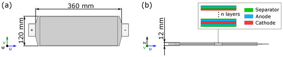
Figure 1.
Structure and cell dimensions of the investigated lithium-ion pouch cell referring to Sprenger et al. [27]: (a) Shows the cell’s length and width. (b) Shows the cell’s thickness and layer structure.
The artificially aged cells were electrically cycled using the same aging strategy as proposed by Sprenger et al. [27]. Aging was done under real EV battery module conditions with several cells serially connected to each other. The used aging strategy was derived from an estimated high-performance customer behavior with an average discharge power of kW and an average charging power of kW for each cell. Charging/discharging was performed in a range between 10% and 90% SOC. A temperature range between and 31 was applied [27]. Electrical aging was performed until a residual capacity of 90% was reached. In order to see a more detailed description of the investigated cell and aging strategy, the reader is referred to [27].
2.2. Post-Mortem Analysis
Regarding the investigation of the electrical aging’s influence on the mechanical properties, the cell layers and their specific aging effects were analyzed in detail. In this work, SEM images from each cell layer were used to determine morphological changes due to aging as these changes might help to create plausible explanations for a changed behavior on cell level. The investigations were made analogously to the procedure of Sprenger et al. [27]. In order to avoid reactions with oxygen, the cells were first opened in a glove box and the layers were washed in dimethyl carbonate (DMC). In a next step, specimens of 5 mm diameter were generated from aging conspicuous spots of the cell layers. In order to investigate the specimens, a Tescan MIRA3 XMU Scanning Electron Microscope was used. Additionally, energy dispersive X-ray (EDX) measurements were conducted to determine changes in the material decomposition through electrochemical aging [27].
2.3. Mechanical Testing
2.3.1. Experimental Design
Aiming to determine the influence of electrical aging on the mechanical behavior of lithium-ion cells, the tests shown in Table 1 were performed. All conducted experiments were done using a ⌀ 30 mm impactor. First, lateral indentation tests were used to determine the difference of fresh and aged cells under in-plane loading (v-direction). Therefore, the cells were sandwiched between two L-shaped sample holders (S235JR), in order to keep the cell in position without applying any external force on the battery surface (see Figure 2a). To confirm the effects for in thickness loads (w-direction) reported by Sprenger et al. [27], additionally quasistatic cylindrical indentation tests were performed. As a short side orientated impactor (v-direction, Figure 2c) was already used by Sprenger et al. [27], the impactor was 90 rotated (impactor length along u-direction, Figure 2b) in the current study aiming to investigate how the anisotropic cell properties influence the aging’s impact. Furthermore, cylindrical indentation tests along the short cell side (v-direction) were performed at 3 m/s at two different SOCs ( 0% and 100%). The measured data was compared to the quasistatic results, conducted by Sprenger et al. [27], to determine the influence of testing velocity on the mechanical performance of the investigated cells. In order to analyze the influence of aging (), testing velocity () and SOC () under in-thickness loads, three material parameters including cell stiffness S, failure displacement and failure force were defined. The cell stiffness S was defined as the linear region of the force-displacement curve after the compressible behavior of the cell, which is characterized by the parabolic characteristic at the beginning of the test curve. Failure displacement and failure force were defined at the point of ISC occurrence. A detailed description of the testing equipment used can be found in the following sections.

Table 1.
Quasistatic (QS) and dynamic (DYN) mechanical tests for the characterization of the investigated lithium-ion pouch cell.
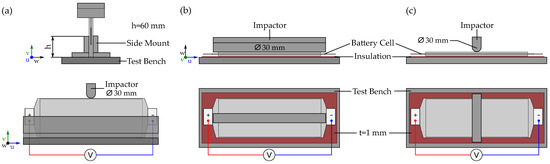
Figure 2.
Visualization of the used experimental setup for mechanical cell testing: (a) Lateral indentation test setup with test bench, L-shaped sample holders and the ⌀30 mm cylindrical impactor. (b) Shows the cylindrical indentation test along the long cell side (u) and (c) the cylindrical indentation test setup along the short cell side (v) [27].
2.3.2. Quasistatic Testing Device
Quasistatic loading experiments were conducted on the hydraulic press PRESTO 420, designed to achieve a maximum load of 420 kN with cross-head speeds residing in the range of mm/s– mm/s. For cylindrical indentation tests (Figure 2b,c), the test specimens were placed on top of a 1 mm thick isolating Pertinax® plate (Kaindl, HP2061) on the movable lower plate of the press. The upward movement of the lower press plate was realized via four guidance rails, positioned symmetrically in the corners of the testing chamber in order to avoid tilting of the plate during movement. Displacement data was recorded by a high-precision linear glass scale encoder with an accuracy of 1 m. A cylindrical indenter with a diameter of 30 mm was mounted perpendicular over the long side of the cell as shown in Figure 2b. The battery sample was deformed with a testing velocity of 1 mm/s. Electrical cell failure, characterised by an ISC, was defined as the criterion of test termination. In the case of lateral indentation (Figure 2a), the test termination criterion was set to 25 mm of displacement after contact between cell and test stamp or if cell failure is detected. Thus, a maximum cell deformation of approximately 40% of the unclamped cell width was achieved. Testing speed for this test case remained unchanged at 1 mm/s with respect to the aforementioned cylindrical indentation tests. The force during quasistatic tests was logged via a NI-9237 bridge input module with a resolution of 24 bits and a sample rate of 50 kS/s using a load cell of the type GTM Serie K 500 kN and a GTM Serie K 20 kN, both of which have an accuracy class of %. The integrated 24-bit NI-9229 voltage input module (0–60 V per channel) measured the voltage signal of the cells during mechanical testing. Data acquisition frequency for all measured signals was set to 1 kHz [25,27].
2.3.3. Dynamic Testing Device
The ELLMAR test rig (see Figure 3), especially designed for dynamic battery experiments at arbitrary SOC levels, was used in this work to conduct high-speed dynamic impact tests with a velocity of 3000 mm/s. Here, the cell and the underlying isolating Pertinax® plate (Kaindl, HP2061), were fixed vertically on a 85 kg horizontal ball bearing guided steel sled, which was next accelerated by an electric driven belt within a 16 m long acceleration section. The above mentioned sled mass was chosen in order to achieve cell failure with a constant velocity during impact. After reaching the constant target velocity at the end of the acceleration section, the sled decoupled from the belt and hit a 30 mm cylindrical impactor, mounted directly on top of a load cell. The resulting force signal was measured by a KISTLER Z20730 piezoelectric load cell with 500 kN nominal force and a sampling rate of 100 kHz. Sled displacement was recorded by a SIKO MSC500 high-precision magnetic sensor, characterized by a resolution of 1 m and an accuracy of ±5 m. Cell voltage was measured during all dynamic tests with a Dewetron DAQP-STG module with a sampling rate of 100 kHz and a voltage input accuracy of ±0.05%.
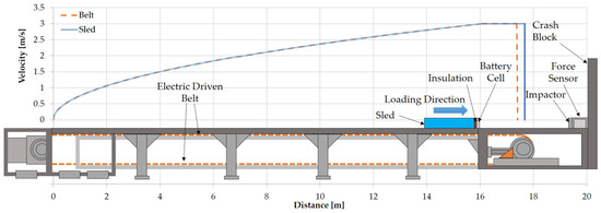
Figure 3.
Illustration of the ELLMAR test rig with movable sled used for dynamic cell tests at 3000 mm/s in this study.
3. Results
In this section the results of the investigated mechanical dependencies of aged cells are presented and compared to fresh cells. First, SEM images and SEM-EDX results of fresh and aged anode samples are analyzed with the goal to explain any observed changes in the mechanical behaviour. In a next step, the behavior of fresh and aged cells under lateral indentation is discussed in greater detail and the differences are highlighted. In the third subsection an orientation dependency assessment of the investigated cells is performed, which is based on the evaluation of the conducted cylindrical indentation tests over the cell’s long side (u) in thickness direction (w). Finally, a comparison of the dynamic indentation tests over the short cell side (v) to the quasistatic results is conducted in order to determine a possible influence of aging on the strain rate dependency of the cell’s mechanical properties.
3.1. Post-Mortem Analysis
The main changes of the investigated cell by electrical aging were found for the anode active material in terms of a grown in size solid electrolyte interface (SEI) layer. This process resulted in growth of the anode’s graphite layer and to an overall thicker cell. Additionally, the appearance of local lithium plating was confirmed with inductively coupled plasma optical emission spectrometry (ICP-OES) measurements in previous investigations [27]. In the current study, further SEM and SEM-EDX measurements of the anode material were performed to specify the observed changes. The results are shown in Figure 4. Investigations of the electrically aged cathode and separator material revealed no significant changes compared to the fresh samples.
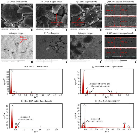
Figure 4.
Analyzing the electrical aging mechanisms at the anode of the investigated lithium-ion cell with SEM-EDX: (a) Surface image of the fresh anode. (b) First conspicous detail of the aged anode showing decomposition products. (c) Second conspicous detail of the aged anode indicating lithium-plating. (d) Cross section image and thickness measurement of the fresh anode. (e–g) Surface images of the aged copper current collector with pitting corrosion effects. (h) Cross section image and thickness measurement of the aged anode. (i) SEM-EDX analysis of the fresh graphite anode. (j,k) SEM-EDX analysis of the first and second conspicous spot of the aged anode. (l) SEM-EDX analysis of the aged copper current collector.
The SEM images (Figure 4a) of the fresh anode display a very clean structure of the graphite particles without any conspicuity. SEM-EDX measurements in Figure 4i show that the graphite particles mainly consist of typical components like carbon and oxygen as well as slight amounts of fluorine and phosphorous. In contrast, for the aged anode surface two suspicious morphological structures were found. Detailed images demonstrate several graphite particles of the aged anodes, which are surrounded by an additional bright layer (Figure 4b). SEM-EDX measurements of this layer in Figure 4j indicate an increased fluorine and phosphorus content. Thus, the additional layer can be characterized as decomposition products between the electrolyte and the anode’s SEI. The mechanism can be explained based on the work of Xiong et al. [20] as follows. During electrical charging the insertion of lithium into the anode particle leads to internal mechanical stresses. Cracks of the SEI layer occur, which evoke a direct contact and side reaction between the electrolyte and the graphite material. As a result an additional layer grows over the cell’s lifetime by the accumulation of this process. This process also results in an electrolyte consumption and a capacity fade [20].
The second conspicuous area of the aged anode can be seen in Figure 4c. Here, various crystal-like structures can be recognized, which show increased proportions of oxygen, taking into account the SEM-EDX measurements shown in Figure 4k. The fact that only an increased oxygen content is present suggests possible lithium plating effects. However, this can only be assumed to be an aging mechanism, since lithium cannot be detected by the means of SEM-EDX. Nevertheless, it must be taken into account that lithium plating effects have already been detected on the aged anode material of the investigated cell. In the following, SEM cross section images (Figure 4d,h) were generated to investigate the impact of these aging effects on the anode’s thickness. The results reveal a thickness increase of 12 m of the investigated aged anode compared to the fresh specimen. Taking into account the number of anode layers, a total increase in cell thickness of mm results, assuming the same growth per layer.
Sprenger et al. [27] reported a lower mechanical strength of the aged anode under tension, which was also mentioned as one possible reason for a lower mechanical strength of aged cells under cylindrical indentation. Thus, in this study the aged copper was investigated by SEM-EDX in order analyze the occurance of corrosion effects due to contact with the electrolyte. A few small spots, indicating a morphological change of the copper material, were found (Figure 4e–g). The mentioned areas can be identified as pitting corrosion of the copper. This can be justified by the specific cavity appearance and the occurrence of several elements besides copper. SEM-EDX measurements of the holes reveal depositions of carbon, oxygen and fluorine (Figure 4l). Whilst taking into account the results of Dai et al. [30], a reaction of the copper current collector with the electrolyte is the most probable reason for the mentioned formation of pitting holes.
The observed corrosion effects may have led to a lower adhesion of the graphite-copper interface and a decrease of the tensile strength of the whole anode due to material lost. However, it must be taken into account that these are minor corrosion effects and the degree of influence on mechanical strength cannot be determined with certainty.
3.2. Lateral Indentation
Lateral indentation (Figure 2a) test results are presented in Figure 5. Due to the high variation in the behavior of each cell during the individual test repetitions, all force-displacement curves are illustrated in the diagram. With the selected test setup, the cell was held in place on the bottom part with two L-shaped cell holders. The cell top remained unconstrained, which allowed cell buckling to occur independently on the cell condition. For this reason also no short circuit was detected during the experiment, since the cell was not restricted in its position within the deformation zone. As seen for the conducted tests in thickness direction [27], a highly reduced force level can be noticed for electrically aged cells for this abuse case. This effect can be explained by the different buckling pattern of fresh and aged cells, originating from the changes to the layer structure of the anode active material. For fresh cells, a relatively large buckled area occurs in the range between 0 mm and 5 mm cell deformation, having a buckling point near the L-shape cell holders. It is possible that fanning out of the individual cell components led to a reduced buckling strength of the laminate. With further intrusion of up to 25 mm, the buckled area is compressed in the lateral direction while the buckling point remained stationary. In contrast, the origin of the buckling point for aged cells was at a position near the test stamp, which led to a smaller buckling area on the cell surface at deformations below 5 mm. A fold over of aged cells was seen, the start of which was identified as the force peak seen in Figure 5a until a deformation of 5 mm. The fold over process subsequently led to continuous deformation of the cell layers in thickness direction with increasing intrusion until 25 mm, where a movement of the buckling point in the lateral cell direction was observed. A lower slope of the force increase was also detected for aged cells when compared to fresh in the deformation range starting after the fold over up to the set maximum deformation. The resulting slope change in the force-displacement characteristic between 5 mm and 25 mm of aged cells originates from the growth of the anode thickness, thus increasing the mechanical preloading within the cell. The growth of an additional layer on the anode was confirmed by SEM-EDX measurements in Section 3.1. Although to a certain extent the swelling amount of the anode can be compensated by the flexibility of the pouch material, overall cell thickness increase is observed. A thicker cell with increased internal preload would increase in this case the resistance to buckling.
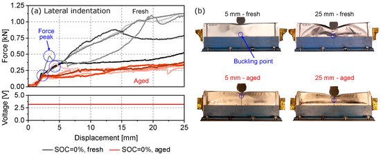
Figure 5.
Comparison of the lateral indentation test results between fresh and aged lithium-ion cells: (a) shows the measured results of force and electrical voltage. (b) shows the buckling behavior of fresh and aged cells at 5 mm and 25 mm displacement.
3.3. Cylindrical Indentation Long Side
Figure 6 shows the difference between the mechanical response of fresh and electrically cycled cells when subjected to cylindrical indentation along the long cell side (Figure 2b). The fresh and aged curves represent the average force-displacement characteristic, calculated from the mechanical response of all three conducted test repetitions. Additionally, error bars are used to visualize the low variation between the individual tests. The results illustrate a significant influence on the displacement at failure by electrical aging. A right-shifted force-displacement characteristic of approximately mm was observed for these cells. Thus, a higher failure displacement of up to +17% was seen compared to fresh cells. In addition, a decreased failure force of % was measured during the current test case. Similar findings were confirmed by previous investigations published by Sprenger et al. [27], where a % decrease in maximum force was explained by the lower mechanical strength of the investigated cell’s aged separator. The increase in failure deformation was explained by the thickening of the SEI layer, which had formed on the surface of the aged anodes. In this case, a thicker anode active material would mean an overall cell thickness increase, which would shift the force-displacement curve to the right. The SEM investigations in Section 3.1 confirm this theory since the SEI change was the main responsible aging mechanism for the aged anode’s thickness increase of approximately mm considering each anode layer of the entire cell. It has to be considered that in the simplified calculation of the anode’s thickness increase in Section 3.1 the same thickness change for each anode layer in the cell was assumed, which may explain the difference of mm compared to the shifted failure displacement .
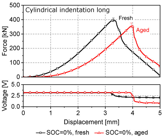
Figure 6.
Comparison of the cylindrical indentation test results along the long cell side for fresh and electrically aged lithium-ion cells at 0% SOC.
The stiffness S of the aged cells, defined as the slope of the linear region in the force-displacement curves in the range between 150 kN–300 kN, decreased about % after cell cycling. The reason for this effect is the formation of a more elastic SEI layer at the outer section [31], which when initially compressed softens the overall mechanical response of the cell. An important issue, having a high priority in the safety assessment of electrically aged cells, is the electrical voltage drop, indicating the occurrence of an ISC inside the cell. In the case of cylindrical indentation over the long cell side a simultaneous force and voltage drop could be identified, as often seen in literature [27,32,33]. In this study a deeper voltage drop of approximately 50% for aged cells was observed compared to fresh cells, which can be also explained by the loss of mechanical strength of the investigated cell’s separator observed by Sprenger et al. [27]. Due to the separator’s lower mechanical strength, a higher number of separator layers may have failed, which led to the deeper voltage drop. Similar effects for aged cells were also reported for aged cells in several publications [26,27,28].
In addition to the decrease in maximum force and the increase in critical displacement at failure , an anisotropic behavior of the cells was seen during cylindrical indentation, regardless of the cell aging status. This effect can be traced back to the combined anisotropic effect of the separator and anode, which also showed a direction dependency during tensile testing. The observed changes to the tensile properties of the mentioned aged components are stated as the reason for the observed changes in the behavior of aged cells, indented in u- and v-direction.
3.4. Cylindrical Indentation Short Side
In order to analyze the strain-rate dependency of the investigated fresh and aged lithium-ion cells, dynamic indentation tests along the short cell side in thickness direction (Figure 2c) were conducted with an impact velocity of 3000 mm/s and the results were compared to previously conducted quasistatic tests (), outlined in the work of Sprenger et al. [27]. Additionally, the difference between 100% SOC and 0% SOC () and the difference between fresh and aged cells () was investigated for both the quasistatic and dynamic load case.
In the work, which was previously conducted by Sprenger et al. [27], a reduction of % of the maximum achieved force was observed for the investigated aged cells compared to fresh cells, when tested at 0% SOC under quasistatic load (Figure 7a). In addition, a right-shifted force-displacement characteristic as seen for cylindrical indentation along the long cell side (see Section 3.3), was observed. In the case of 100% SOC a small decrease of about % between fresh and aged cells could be determined. An increase in testing velocity () resulted in an overall different curve characteristic (Figure 7b), when compared to the quasistatic load case. Four force peaks could be distinguished until cell failure for both fresh and aged cells, which were only noticeable under dynamic loading conditions. The first two peaks (“1” and “2”) are represented by a force plateau, which can be associated with the influence of the electrolyte on the mechanical behaviour of the cells. During highly dynamic load cases by compressing the internal cell layers, which are soaked in electrolyte solution, the electrolyte is being pressed out of the material pores with high velocity, which results in the observed force plateaus. A second important difference to quasistatic loads is the increased cell stiffness S of up to +57% for fresh and +75% for aged cells. This effect can be attributed to the solid-fluid interaction between the electrolyte and the active material coatings at different loading velocities, as seen from studies comparing the mechanical behavior of dry and wet cells, tested at different speeds [17,18]. During dynamic tests the electrolyte seems to flow in the porous coating material, causing additional viscous forces [28]. This would in turn mean as the loading velocity increases, the flow of electrolyte is accelerated which in turn results in higher material stiffness.
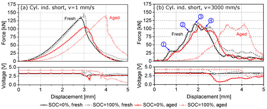
Figure 7.
Comparison of the cylindrical indentation test results along the short cell side for fresh and electrical aged lithium-ion cells: (a) Quasistatic results at v = 1 mm/s by Sprenger et al. [27] and (b) dynamic results at v = 3000 mm/s.
Regardless of the aging state or SOC, two additional force plateaus (“3” and “4”) can be noticed in the range between 80 kN and 120 kN under dynamic loading. A similar curve characteristic was reported for the anode material under compression [23,27]. In the mentioned study, the force plateau was clearly evoked by the graphite material’s failure, which was followed by a further force increase. As there was no ISC detected at this point for the dynamically tested cells in this study, a local damage of the graphite under the impactor could explain the third force plateau. For all cell conditions the last force peak (“4”) indicated the point of electromechanical cell failure, which coincided with the voltage drop, detected for the tested batteries. At this point, cell failure was observed at lower peak forces of up to % compared to the quasistatic tests independent of the aging state and SOC. Furthermore, a decrease of the failure displacement between % and % was noticed by increasing the testing velocity.
The influence of aging on the mechanical behavior of cells during dynamic loading was clearly visible. As the force-displacement curves’ shape remained similar after aging, an observed difference was however the decrease in size of the observed plateaus, which can be explained by the reduction of electrolyte content after aging. The curves of aged cells at 0% SOC showed a shift to the right ( +7%), which is caused by the thickness increase of the cell due to anode growth and a lower cell stiffness S of up to % compared to fresh cells. For charged cells the changed failure displacement after aging was even more significant (+60%). Reason for this was the cell’s additional thickness increase of approximately mm when fully charged [27]. As a result under quasistatic loading higher failure displacements of up to +32% were noticed. For electrically aged cells at 0% SOC a % decrease of failure force under dynamic testing velocity compared to fresh cells could be observed. At fully charged state, the failure force for aged cells was approximately +6% higher as for fresh cells. Independently of the SOC, a deeper voltage drop compared to fresh cells could be noticed. This behavior may result in a higher energy release after ISC, which can e.g., evoke higher temperatures after an internal short [26,27,28].
Finally, it can be derived that electrical aging led independently of the SOC or the testing velocity to a decreased cell stiffness S and a higher failure displacement . A lower failure force for electrical aged cells was mainly seen at 0% SOC. Compared to fresh cells, aged cells showed a higher dependency regarding the SOC. Especially the change of and were strongly influenced by the SOC for aged cells. In contrast, for fresh cells a higher SOC only evoked a small increase of of up to +8% and an increased failure force of up to +5%. A summary of the parameter analysis for all conducted load case scenarios, SOC and SOH levels from both studies can be seen in Table 2.
Table 2.
Change of cell stiffness S, failure displacement and failure force and how these parameters are influenced by increasing the (a) testing velocity (), (b) the state of charge () or (c) using an electrical aged cell compared to a fresh cell ().
4. Summary and Conclusions
In this study, mechanical tests of fresh and electrically aged pouch cells were conducted to investigate the influence of electrical aging on lithium-ion cells’ mechanical behavior under typical crash load cases. For the first time, the electrical aging’s impact under lateral cell loads was investigated. Beside electrical aging, also the influence of the SOC and the testing velocity were taken into account for loads, applied to the investigated lithium-ion cells in thickness direction. Furthermore, SEM-EDX analyses were used to explain the observed changes to the mechanical behavior of aged cells in the current and previous investigations.
It was shown by cylindrical indentation tests that electrical aging has a significant impact on the cell’s mechanical properties in thickness direction. Compared to fresh cells, a right-shifted force-displacement curve, which led to a higher failure deformation of up to +17% was observed for aged cells cells at 0% SOC. SEM analyses revealed that the main responsible mechanism for this change is the aged cell’s thickness increase due to the growth of the SEI on the anode active material. The observed shift of the force-displacement characteristic was clearly increased for fully charged cells, which correlated with the thickness change between 0% and 100% SOC of the investigated cell. Furthermore, it was shown that electrical aged cells at 0% SOC show a lower mechanical failure force in a range of % and % under quasistatic cylindrical indentation, dependant on the impactor orientation.
Dynamic cylindrical indentation tests revealed a special curve characteristic with four conspicuous force peaks. Peak one and two were identified as effects evoked by the compression of the electrolyte between the cell layers. These force peaks were slightly decreased due to the electrolyte consumption for aged cells. The third peak of the dynamic curve was justified with the internal failure of the anodes’ graphite layer. Finally, the fourth peak indicated cell failure by a simultaneous voltage drop. For aged cells at 0% SOC a lower failure force of % was noticed. In contrast, aged cells showed a higher failure force of +6% at 100% SOC compared to fresh cells. Increasing the testing velocity evoked a higher cell stiffness and lower failure forces in every test case. It was shown additionally that regardless of the test speed, aged cells cause a steeper and deeper voltage drop after failure, which can lead to faster and higher energy release.
Under lateral loading neither fresh or electrically aged cells showed an internal short circuit up to 25 mm deformation. Aged cells exhibited greatly reduced force values, which could be justified by different buckling behavior using image recordings of the tests. Fresh cells showed buckling close to the used specimen holder, whereas aged cells buckled closer to the impactor. For aged cells, a force drop could be identified at the beginning of the deformation, which led to a folding of the upper part of the cell. Subsequently, the cell layers were deformed in the thickness direction, resulting in reduced force values.
The most important findings of this study can be summarized as follows:
- The investigated aged pouch cells show a right-shifted force-displacement curve, a lower stiffness and deeper voltage drops under mechanical indentation in thickness direction compared to fresh cells. Furthermore, lower failure forces of aged cells can be noticed at 0% SOC.
- The right-shifted force-displacement curve in the thickness direction of the cell is caused by aging effects such as the growth of the SEI layer as well as lithium plating effects. The thickness increase of the anode examined in the SEM measurements correlates with the shift of the force-displacement curve at 0% SOC. This demonstrates electrolyte consumption within the cell, which has a direct influence on the size of the plateaus in the dynamic test.
- Under lateral loading, the fresh cell shows lower buckling stability. The most probable reason for this is the lower mechanical stability of the laminated composite. Aged cells are subjected to higher mechanical pressure in the thickness direction, which compresses the cell interior.
- Regardless of the aging condition, the cell under study shows two significant force drops under dynamic cylindrical indentation, with the former presumably involving failure of only the anode graphite layer and the latter involving failure of the separator.
- The influence of state of charge is similar under quasistatic and dynamic loading. Aged cells show a higher dependence on the state of charge.
- The tensile strength of the aged anode may be reduced by aging effects such as pitting corrosion, as these effects can lead to reduced adhesion between the current collector and the active material.
For future investigations, the authors recommend a complete restraint of the cell in order to investigate also lateral loading under more realistic cell module conditions, where neighboring cells can restrict buckling of the loaded cell. Thus, short circuit detection could be also observed.
Author Contributions
Conceptualization: M.S., G.K. and C.E.; Methodology: M.S., G.K., W.S. and C.E.; Formal analysis, data curation: M.S. and G.K.; Investigation, visualization: M.S., G.K., F.S. and C.E.; Writing—original draft preparation: M.S. and G.K.; Writing—review and editing: N.D., F.S., W.S. and C.E.; Supervision: N.D. and W.S.; Project administration: M.S. and C.E.; funding acquisition: C.E. All authors have read and agreed to the published version of the manuscript.
Funding
Parts of this work were conducted in the research project SafeLIB. The COMET Project SafeLIB is funded within the framework of COMET—Competence Centers for Excellent Technologies by BMK, BMDW, the Province of Upper Austria, the province of Styria as well as SFG. The COMET Program is managed by FFG.
Institutional Review Board Statement
Not applicable.
Informed Consent Statement
Not applicable.
Data Availability Statement
Not applicable.
Acknowledgments
This publication is supported by TU Graz Open Access Publishing Fund. The authors thank Severin Hahn, Rainer Schwarz and Patrick Brix for the technical exchange. We thank Philipp Bellucci for the preparation of the SEM images. We also thank Ajla Purkovic and Christian Trummer for assistance with the experimental work. The responsibility for this publication lies with the authors. Open Access Funding by the Graz University of Technology.
Conflicts of Interest
The authors declare no conflict of interest.
Abbreviations
The following abbreviations are used in this manuscript:
| C-Rate | Charging rate |
| DMC | Dimethyl carbonate |
| DoD | Depth of discharge |
| EDX | Energy dispersive X-ray |
| EV | Electric vehicle |
| ICP-OES | Inductively coupled plasma optical emission spectrometry |
| ISC | Internal short circuit |
| LIBs | Lithium-ion batteries |
| NCM | Lithium nickel manganese cobalt oxide |
| SEI | Solid electrolyte interface |
| SEM | Scanning electron microscopy |
| SOC | State of Charge |
| SOH | State of Health |
| TR | Thermal runaway |
References
- Jaguemont, J.; Boulon, L.; Dubé, Y. A comprehensive review of lithium-ion batteries used in hybrid and electric vehicles at cold temperatures. Appl. Energy 2016, 164, 99–114. [Google Scholar] [CrossRef]
- Abaza, A.; Ferrari, S.; Wong, H.K.; Lyness, C.; Moore, A.; Weaving, J.; Blanco-Martin, M.; Dashwood, R.; Bhagat, R. Experimental study of internal and external short circuits of commercial automotive pouch lithium-ion cells. J. Energy Storage 2018, 16, 211–217. [Google Scholar] [CrossRef]
- Yang, R.; Xiong, R.; Ma, S.; Lin, X. Characterization of external short circuit faults in electric vehicle Li-ion battery packs and prediction using artificial neural networks. Appl. Energy 2020, 260, 114253. [Google Scholar] [CrossRef]
- Greve, L.; Fehrenbach, C. Mechanical testing and macro-mechanical finite element simulation of the deformation, fracture, and short circuit initiation of cylindrical Lithium ion battery cells. J. Power Sources 2012, 214, 377–385. [Google Scholar] [CrossRef]
- Sahraei, E.; Campbell, J.; Wierzbicki, T. Modeling and short circuit detection of 18650 Li-ion cells under mechanical abuse conditions. J. Power Sources 2012, 220, 360–372. [Google Scholar] [CrossRef]
- Sahraei, E.; Kahn, M.; Meier, J.; Wierzbicki, T. Modelling of cracks developed in lithium-ion cells under mechanical loading. RSC Adv. 2015, 5, 80369–80380. [Google Scholar] [CrossRef]
- Sahraei, E.; Bosco, E.; Dixon, B.; Lai, B. Microscale failure mechanisms leading to internal short circuit in Li-ion batteries under complex loading scenarios. J. Power Sources 2016, 319, 56–65. [Google Scholar] [CrossRef]
- Xu, J.; Liu, B.; Hu, D. State of charge dependent mechanical integrity behavior of 18650 lithium-ion batteries. Sci. Rep. 2016, 6, 21829. [Google Scholar] [CrossRef]
- Xia, Y.; Chen, G.; Zhou, Q.; Shi, X.; Shi, F. Failure behaviours of 100% SOC lithium-ion battery modules under different impact loading conditions. Eng. Fail. Anal. 2017, 82, 149–160. [Google Scholar] [CrossRef]
- Li, W.; Xia, Y.; Zhu, J.; Luo, H. State-of-Charge Dependence of Mechanical Response of Lithium-Ion Batteries: A Result of Internal Stress. J. Electrochem. Soc. 2018, 165, 1537–1546. [Google Scholar] [CrossRef]
- Tsutsui, W.; Siegmund, T.; Parab, N.; Liao, H.; Nguyen, T.; Chen, W. State-of-Charge and Deformation-Rate Dependent Mechanical Behavior of Electrochemical Cells. Exp. Mech. 2018, 58, 627–632. [Google Scholar] [CrossRef]
- Xu, J.; Liu, B.; Wang, L.; Shang, S. Dynamic mechanical integrity of cylindrical lithium-ion battery cell upon crushing. Eng. Fail. Anal. 2015, 53, 97–110. [Google Scholar] [CrossRef]
- Kisters, T.; Sahraei, E.; Wierzbicki, T. Dynamic impact tests on lithium-ion cells. Int. J. Impact Eng. 2017, 108, 205–216. [Google Scholar] [CrossRef]
- Kisters, T.; Kuder, J.; Töpel, A.; Langkemper, R.; Nau, S.; Schopferer, S. Strain-rate dependence of the failure behavior of Lithium-Ion pouch cells under impact loading. J. Energy Storage 2021, 41, 102901. [Google Scholar] [CrossRef]
- Zhu, J.; Luo, H.; Li, W.; Gao, T.; Xia, Y.; Wierzbicki, T. Mechanism of strengthening of battery resistance under dynamic loading. Int. J. Impact Eng. 2019, 131, 78–84. [Google Scholar] [CrossRef]
- Tancogne-Dejean, T.; Grolleau, V.; Mohr, D. Strain rate dependent plasticity of lithium-ion pouch cells: Experiments and simulations. Int. J. Impact Eng. 2022, 159, 104048. [Google Scholar] [CrossRef]
- Kisters, T.; Keshavarzi, M.; Kuder, J.; Sahraei, E. Effects of electrolyte, thickness, and casing stiffness on the dynamic response of lithium-ion battery cells. Energy Rep. 2021, 7, 6451–6461. [Google Scholar] [CrossRef]
- Raffler, M.; Sinz, W.; Erker, S.; Brunnsteiner, B.; Ellersdorfer, C. Influence of loading rate and out of plane direction dependence on deformation and electro-mechanical failure behavior of a lithium-ion pouch cell. J. Energy Storage 2022, 56, 105906. [Google Scholar] [CrossRef]
- Birkl, C.R.; Roberts, M.R.; McTurk, E.; Bruce, P.G.; Howey, D.A. Degradation diagnostics for lithium ion cells. J. Power Sources 2017, 341, 373–386. [Google Scholar] [CrossRef]
- Xiong, R.; Pan, Y.; Shen, W.; Li, H.; Sun, F. Lithium-ion battery aging mechanisms and diagnosis method for automotive applications: Recent advances and perspectives. Renew. Sustain. Energy Rev. 2020, 131, 110048. [Google Scholar] [CrossRef]
- Xu, J.; Jia, Y.; Liu, B.; Zhao, H.; Yu, H.; Li, J.; Yin, S. Coupling Effect of State-of-Health and State-of-Charge on the Mechanical Integrity of Lithium-Ion Batteries. Exp. Mech. 2018, 58, 633–643. [Google Scholar] [CrossRef]
- Zhang, X.; Zhu, J.; Sahraei, E. Degradation of battery separators under charge–discharge cycles. RSC Adv. 2017, 7, 56099–56107. [Google Scholar] [CrossRef]
- Wu, Z.; Cao, L.; Hartig, J.; Santhanagopalan, S. (Invited) Effect of Aging on Mechanical Properties of Lithium Ion Cell Components. ECS Trans. 2017, 77, 199–208. [Google Scholar] [CrossRef]
- Fink, K.; Santhanagopalan, S.; Hartig, J.; Cao, L. Characterization of Aged Li-Ion Battery Components for Direct Recycling Process Design. J. Electrochem. Soc. 2019, 166, 3775–3783. [Google Scholar] [CrossRef]
- Kovachev, G.; Ellersdorfer, C.; Gstrein, G.; Hanzu, I.; Wilkening, H.M.R.; Werling, T.; Schauwecker, F.; Sinz, W. Safety assessment of electrically cycled cells at high temperatures under mechanical crush loads. eTransportation 2020, 6, 100087. [Google Scholar] [CrossRef]
- Liu, Y.; Xia, Y.; Zhou, Q. Effect of low-temperature aging on the safety performance of lithium-ion pouch cells under mechanical abuse condition: A comprehensive experimental investigation. Energy Storage Mater. 2021, 40, 268–281. [Google Scholar] [CrossRef]
- Sprenger, M.; Dölle, N.; Schauwecker, F.; Raffler, M.; Ellersdorfer, C.; Sinz, W. Multiscale Analysis and Safety Assessment of Fresh and Electrical Aged Lithium-Ion Pouch Cells Focusing on Mechanical Behavior. Energies 2022, 15, 847. [Google Scholar] [CrossRef]
- Liu, Y.; Xia, Y.; Xing, B.; Zhou, Q. Mechanical-electrical-thermal responses of lithium-ion pouch cells under dynamic loading: A comparative study between fresh cells and aged ones. Int. J. Impact Eng. 2022, 166, 104237. [Google Scholar] [CrossRef]
- Preger, Y.; Torres-Castro, L.; Rauhala, T.; Jeevarajan, J. Perspective—On the Safety of Aged Lithium-Ion Batteries. J. Electrochem. Soc. 2022, 169, 030507. [Google Scholar] [CrossRef]
- Dai, S.; Chen, J.; Ren, Y.; Liu, Z.; Chen, J.; Li, C.; Zhang, X.; Zhang, X.; Zeng, T. Electrochemical corrosion behavior of the copper current collector in the electrolyte of lithium-ion batteries. Int. J. Electrochem. Sci. 2017, 12, 10. [Google Scholar] [CrossRef]
- Shin, H.; Park, J.; Han, S.; Sastry, A.M.; Lu, W. Component-/structure-dependent elasticity of solid electrolyte interphase layer in Li-ion batteries: Experimental and computational studies. J. Power Sources 2015, 277, 169–179. [Google Scholar] [CrossRef]
- Sahraei, E.; Meier, J.; Wierzbicki, T. Characterizing and modeling mechanical properties and onset of short circuit for three types of lithium-ion pouch cells. J. Power Sources 2014, 247, 503–516. [Google Scholar] [CrossRef]
- Luo, H.; Xia, Y.; Zhou, Q. Mechanical damage in a lithium-ion pouch cell under indentation loads. J. Power Sources 2017, 357, 61–70. [Google Scholar] [CrossRef]


Disclaimer/Publisher’s Note: The statements, opinions and data contained in all publications are solely those of the individual author(s) and contributor(s) and not of MDPI and/or the editor(s). MDPI and/or the editor(s) disclaim responsibility for any injury to people or property resulting from any ideas, methods, instructions or products referred to in the content. |
© 2023 by the authors. Licensee MDPI, Basel, Switzerland. This article is an open access article distributed under the terms and conditions of the Creative Commons Attribution (CC BY) license (https://creativecommons.org/licenses/by/4.0/).