Abstract
An Li metal anode has been proposed as a promising candidate for high energy density electrode material. However, the direct use of Li metal can lead to uncontrollable dendrite growth and massive volume expansion, which generates severe safety hazards and hinders practical application. Herein, we developed a novel Li anode by thermal infusion into three-dimensional (3D) carbon cloth (CC) modified with lithiophilic CuO nanorod arrays (denoted as Li@CuO−CC). The 3D CC offers sufficient space for Li storage and adequate electrolyte/electrode contact for fast charge transfer. The uniformly distributed CuO nanorod arrays can improve the lithiophilicity of CC and redistribute the Li-ion flux on the substrate, leading to uniform Li stripping/plating behavior. As a result, the Li@CuO−CC electrode exhibits a dendrite-free feature and superior cycling performance over 1000 h with low overpotential (12 mV) at a current density of 1 mA cm−2 in the symmetrical cell without significant fluctuations. When coupled with an LiFePO4 cathode, the full cell displays high specific capacity (133.8 mAh g−1 at 1 C), outstanding rate performance, and cycle stability (78.7% capacity retention after 600 cycles at 1 C). This work opens a new approach for the development of construction of an advanced anode for Li metal batteries.
1. Introduction
The ever-growing demand for portable electronic devices and electric vehicles has driven the development of higher energy density rechargeable batteries beyond conventional Li-ion batteries [1,2]. Li metal is an attractive anode on account of its ultrahigh theoretical capacity (3860 mAh g−1), lowest reduction potential (−3.04 V vs. standard hydrogen electrode), and light weight (0.534 g cm−3) [3,4,5]. However, its practical application has been limited due to uncontrollable coral-like Li dendrite growth, which can cause serious safety hazards [6,7]. In addition, during the continuous stripping/plating process, the Li metal anode (LMA) shows an infinite volume change, leading to low Coulombic efficiency (CE).
Various efforts have been devoted to solving these issues, such as electrolyte modification [8], artificial SEI layer design [9], solid electrolyte engineering [10,11], and rational anode construction [12,13,14]. Herein, three-dimensional (3D) metal [12,13] and carbonyl [14,15] framework hosts have continuous channels and large surface area, which is beneficial to the uniform deposition of Li. Compared to the metal framework, a carbonyl framework shows various inherent merits, including low cost, thermal stability, mechanical strength, and light weight [16], which favors high energy density and supplies accommodation of more Li. Stucky et al. [17] designed a dendrite-free collector for Li deposition based on carbon fiber papers. Cui et al. [18] used interconnected amorphous hollow carbon nanospheres as spatially heterogeneous current collectors. The outstanding dendrite-free feature was attributed to the hollow carbon nanosphere layer, which could move up and down to regulate the interspace for Li deposition. The carbonyl framework as mentioned above pre-stores Li through the electrodeposition process. This approach requires an inevitable assembly/disassembly process, which may introduce impurities or side reactions. More excitingly, Cui et al. [19] first developed molten Li infusion into the sparked rGO framework. It was indicated that pre-storing Li into framework hosts is a convenient and maneuverable method [19,20,21,22]. However, this strategy needs a host with superior lithiophilicity and thermal stability over 180 °C (the melting point of Li). A 3D carbon cloth (CC) composed of interwoven carbon fiber is a feasible candidate framework host because of its flexibility, electrical conductivity, and excellent mechanical and thermal stability [23,24]. Moreover, 3D CC can provide sufficient contact area and relieve the volume expansion. Notably, it is very difficult to wet the untreated CC by the molten Li [25]. Consequently, exploiting lithiophilic materials such as Ag [26], Au [27], CoO [28], TiO2 [29], ZnO [30], etc., is urgently needed to decorate the framework. CuO has been proven to have exceptional lithiophilicity, which can ensure uniform deposition. For example, various CuO composites with different morphologies on metal framework hosts have been reported with improved performance for LMA [31,32,33,34]. Yang et al. fabricated surface-grown lithophilic CuO nanosheets on a planar Cu foil as an advanced LMA host [31]. Benefiting from the lithiophilic nature of the CuO layer, this electrode exhibited flat voltage profiles and superior cycling performance over 700 h at 0.5 mA cm−2. Cheng et al. developed CuO nanowire arrays on Cu foam by solution-based etching and subsequent dehydration [34]. The optimized anode maintained a high CE of 95.5% for 150 cycles at 3 mA cm−2 and a prolonged lifespan of 280 cycles at 0.5 mA cm−2. However, CuO has rarely been reported as a lithiophilic layer for molten Li infusion to CC. It is believed that the CuO decorated-CC host can favor uniform Li deposition and excellent cycling stability.
In this work, we demonstrate a facile strategy for vertical CuO nanorod arrays on CC, which further reacts with molten Li to obtain a 3D dendrite-free Li@CuO−CC electrode. The commercial CC with a porous structure offers an ample internal space for pre-storing Li and relieves the infinite volume change during the stripping/plating process. In addition, introducing CuO can transform a lithiophobic CC into a lithiophilic framework, thus guiding uniform Li deposition with small nucleation overpotential. Interestingly, Li2CuO2 species formed during the molten Li infusion process. Li2CuO2 has a high ionic conductivity, and CC possesses a high electronic conductivity. The integrated effects ensure fast charge transfer kinetics for the Li/Li-ion redox reaction. Based on these synergetic effects, the Li@CuO−CC electrode exhibits superior electrochemical performance in the symmetrical cell and as well a full cell coupled with the LiFePO4 (LFP) cathode. We also investigated the mechanism of enhanced performance based on stripping/plating behavior. This work provides a practical idea for regulating the surface and structural properties of carbonyl framework hosts toward a superior dendrite-free anode.
2. Materials and Methods
2.1. Fabrication of CuO Nanorod Arrays Decorated CC (CuO−CC)
The CuO−CC framework host was synthesized through the in situ growth method on CC. Typically, the pristine CC was punched into a rectangle with a length of 4 cm and a width of 2 cm, which was soaked in the concentrated nitric acid solution for 12 h to shift from the hydrophobic to the hydrophilic state. Then the CC was washed with ethanol and deionized water three times and then dried in a vacuum oven at 50 °C for 1 h. Then 0.1 g Cu(AC)2·2H2O and 0.1 g hexamethylenetetramine (C6H12N4) (HMT) were dissolved in 30 mL deionized water for 0.5 h to form a homogeneous blue solution. The mixture solution and the as-prepared CC were transferred into a 50 mL Teflon autoclave for hydrothermal treatment at 100 °C for 10 h. After cooling to the room temperature, the sample was retrieved and then washed with deionized water and ethanol several times. Finally, the as-prepared CuO−CC was dried in a vacuum oven at 50 °C overnight.
2.2. Fabrication of Li@CuO−CC Electrode
The CuO−CC framework host was cut into a disk with a diameter of 1.2 cm. Thermal infusion was operated in an argon-filled glove box with O2 and H2O less than 0.1 ppm under 320 °C. The as-prepared CuO−CC disk was contacted with the top of the molten Li, and the Li infiltrated into the entire disk spontaneously, fabricating a Li@CuO−CC anode.
2.3. Characterization
The crystal phases were determined using X-ray powder diffraction (XRD, Bruker D8) in a 2q range from 10 to 80. The surface species were identified by X-ray photoelectron spectra (XPS, Thermo ESCALAB250Xi) with Al Kα radiation (hν = 280.00 eV). The morphologies and energy dispersive spectrometer (EDS) mapping were obtained by field-emission scanning electron microscopy (SEM, JEOL JSM-7610F). The cycled cells were disassembled in the argon-filled glove box and then rinsed with dimethyl carbonate (DMC) three times to remove the residual electrolyte before characterization
2.4. Computational Method
Based on the DMol3 module in Material Studio software, the density function theory (DFT) calculation was carried out to determine the adsorption energy of Li atoms on the carbon and CuO surface. The Perdew–Burke–Ernzerhof functional within the generalized gradient approximation adopted the exchange-correlation function [35,36]. The energy cutoff was set to 450 eV, and the vacuum thickness was set to be 15 Å. Then 2 × 2 (002) graphitic carbon supercells and 2 × 2 (111) CuO supercells with three-layer lattice planes were applied to simulate the surfaces of graphitic carbon and the CuO surface, respectively. Monkhorst−Pack 5 × 5 × 1 k-mesh represented the Brillouin zone. The adsorption energy of a single Li atom was estimated by the following equation:
Eads refers to the adsorption energy of a single Li atom. Etotal refers to the total energy of Li adsorbed on the model surface. Eslab refers to the energy of the isolated model without the surface layer of Li. ELi refers to the chemical potential of a single Li atom in bcc bulk, respectively.
2.5. Electrochemical Measurements
The electrochemical performance of the Li@CuO−CC electrode was evaluated using a CR2025-type coin cell, which was assembled in an argon-filled glove box with an O2 and H2O content less than 0.1 ppm. The separator type was Celgard 2400 polypropylene porous membrane, and the electrolyte was 1.0 M lithium hexafluorophosphate in a mixed solvent of ethylene carbonate/dimethyl carbonate (1:1, v/v). In symmetrical cells, identical electrodes (bare Li foil, or Li@CuO−CC) were employed as the working and counter electrodes. In a full cell, the cathode was prepared by mixing the commercial LFP powders, carbon black, and polyvinylidene fluoride at a weight ratio of 8:1:1 in N-methyl pyrrolidone as the homogeneous slurry and then coating it onto Al foil. The cathode was punched to disks of 1.2 cm in diameter with a loading mass of 1.5 mg cm−2. Electrochemical impedance spectroscopy (EIS) was measured on a CHI 760E electrochemical workstation by applying an AC voltage over a frequency range from 105 Hz to 10−2 Hz with an amplitude of 5 mV.
3. Results and Discussion
3.1. Synthesis and Morphology of the Li@CuO−CC Electrode
As illustrated in Figure 1a, the Li@CuO−CC electrode was obtained by the hydrothermal method combined with a thermal infusion process. Briefly, HMT decomposed to OH− during the hydrolysis process, Cu2+ adsorbed on CC reacted with OH− to form nanostructured CuO, and then CuO was uniformly anchored on the surface of the CC substrate. After that, the Li@CuO−CC electrode was obtained by a facile thermal infusion method. Figure 1b depicts the digital images; the grey CC was converted to black after hydrothermal treatment. The as-obtained electrode exhibited a silvery-white luster appearance with legible CC skeletons.
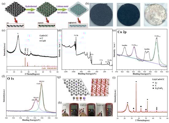
Figure 1.
(a) Schematic illustration of the synthesis process of the Li@CuO−CC electrode. (b) Digital images of bare CC, CuO−CC, and Li@CuO−CC. (c) XRD patterns of CuO−CC. (d–f) XPS patterns of CuO−CC. (g) The most stable adsorption configurations of Li atom on the structure of graphite carbon and CuO. (h) Resistance measurement of bare CC, CuO−CC, and Li@CuO−CC with diameters of 1.2 cm. (i) XRD patterns of Li@CuO−CC.
XRD was performed to verify the purity and phase, and the results are displayed in Figure 1c. The peaks of 25.7 and 42.8 degrees were attributed to the (002) and (101) planes of graphite carbon, respectively. Moreover, the peaks of 35.4 and 38.7 degree referred to (002) and (111) of CuO (PDF#45-0937), respectively. No other peak such as metallic Cu or Cu2O was detected. It was clearly indicated that no impurities were produced during the hydrothermal process. To obtain more information about the surface physiochemical properties and valence states of the as-obtained composite, the XPS test was also carried out. Figure 1d depicts the XPS peaks with characteristic O 1s, Cu 2p, and C 1s, indicating the existence of O, Cu, and C elements, respectively. As shown in Figure 1e, binding energy values of 934.2 and 954.2 eV were attributed to Cu 2p3/2 and 2p1/2 with the presence of two satellite peaks at 942.6 and 962.4 eV, respectively [37]. The high-resolution O 1s (Figure 1f) spectrum consisted of two peaks at 529.6 and 531.2 eV, which were ascribed to the lattice oxygen in the CuO phase and the oxygen of the hydroxide ion, respectively [38]. Thus, pure CuO successfully coated on the surface of CC according to the above results. The growth mechanism of the CuO−CC framework host could be attributed to the dual action of hydrothermal and HMT [39], which is presented as below:
After the fabrication step of the CuO−CC framework host, a facile thermal infusion process was conducted to fabricate the Li@CuO−CC electrode. The liquid Li spontaneously flowed into the framework in less than 10 s. However, the bare CC could not be infiltrated by the molten Li, even after elevating the temperature up to 400 °C or prolonging the thermal time. This enhanced lithiophilicity of the CuO−CC framework host was probably attributed to the chemical reaction between molten Li and the CuO nanorod [33]. Figure 1g illustrates the most stable adsorption configurations of DFT calculations for a Li atom on graphite carbon and CuO surfaces, respectively. The calculated results showed much larger Li absorption energy on the CuO (111) surface (−3.53 eV) than on the C (002) surface (−0.64 eV), which indicated that CuO had more lithiophilicity compared with the CC substrate. Figure 1h shows that the resistance of the as-obtained CuO−CC (7.6 Ω for a diameter of 1.2 cm) was mildly higher than that of CC (3.4 Ω), which demonstrated that the CuO layer on the carbon substrate would not greatly increase the internal resistance of the battery. In comparison, the Li@CuO−CC electrode, with a resistance as low as 1 Ω, had excellent electric conductivity. The XRD pattern of the Li@CuO−CC electrode is given in Figure 1i. Apart from the broad peak of the carbon substrate located at 38.7 degrees, the remaining peaks corresponded to Li and Li2CuO2, respectively. The results indicated that the CuO layer reacted with molten Li and, moreover, the CC substrate kept good stability during the Li-infusing process. The formed Li2CuO2 compounds with layered structures had high Li ionic diffusion and electric conductivities, which could supply an inner transport path for Li-ions in the Li deposition process [40].
SEM characterization was conducted to investigate the morphology of bare CC (Figure 2a) and the as-obtained CuO−CC (Figure 2b,c). The bare CC consisted of carbon fibers with diameters of about 7 μm, and the surface was relatively smooth. The morphology of CuO−CC was composed of a hierarchical 3D structure. The primary structure was microsized carbon fiber, which supplied physical space confinement for later Li deposition on each fiber. The secondary structure included vertically-aligned rod-like CuO nanoarrays with diameters of ~25 nm, reacting with molten Li to reduce surface energy. The vertically-aligned CuO nanorod arrays could supply a capillary effect, which was beneficial for thermal infusion of molten Li. EDS mapping confirmed the existence of Cu and O elements on a single carbon fiber (Figure 2d), verifying the uniform growth of CuO on the surface of the carbon substrate. SEM images of the Li@CuO−CC electrode (Figure 2e) indicated that the CuO−CC framework host was buried under the thick Li metal, which contributed to the fast reaction between Li and CuO. The Li@CuO−CC electrode, with a thickness of~446 μm, showed a relatively smooth surface. As shown in Figure 2f, the cross section of electrode exhibited a slight fluctuation, indicating the reserved 3D framework of CC during the Li thermal infusion process.
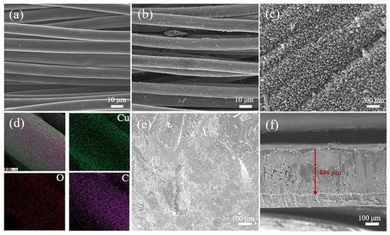
Figure 2.
SEM images of (a) bare CC and (b,c) CuO−CC. (d) EDS mapping and element distributions of CuO−CC. (e,f) SEM images of Li@CuO−CC.
3.2. Electrochemical Performance of the Symmetrical Cell
We assembled a Li@CuO−CC symmetrical cell to evaluate its electrochemical performance. Moreover, a symmetrical cell with two identical Li foils was fabricated as the control. Figure 3a–c exhibits the voltage profiles of both the Li@CuO−CC and bare Li symmetrical cells at current densities of 1 mA cm−2, 3 mA cm−2, and 5 mA cm−2 with the same cycling capacity of 1 mAh cm−2, respectively. Overpotential is considered as the driving force for Li stripping/plating [41], which is an important parameter to evaluate the performance of Li metal. Figure 3a depicts the excellent cycling stability of both symmetrical cells during the initial 100 h. The bare Li and Li@CuO−CC symmetrical cells showed overpotential of around 25 mV and 12 mV, respectively. However, the bare Li symmetrical cell exhibited a great increased overpotential after 100 h, and it finally displayed a large overpotential up to 70 mV at 300 h, which was attributed to the repeatedly generated SEI [42]. In contrast, the Li@CuO−CC symmetrical cell possessed a prolonged lifespan of more than 1000 h (500 cycles), with a much lower overpotential (12 mV). At the current density of 3 and 5 mA cm−2, the Li@CuO−CC symmetrical cell still exhibited enhanced cycling performance with low overpotential (32 mV at 400 h, and 50 mV at 310 h), but the bare Li symmetrical cell showed increased overpotential or violently fluctuated voltage hysteresis. The Li@CuO−CC symmetrical cell still stably cycled over 400 h, even at a current density of 3 mA cm−2 with a higher capacity of 3 mAh cm−2, which was much superior to the bare Li symmetrical cell (Figure 3d). The 3D hierarchical architecture of CC decorated with CuO nanorod arrays contributed to the lower Li ionic transport resistance of the composite electrode. The rate performance of the symmetrical cell was evaluated at a mutative current density. As depicted in Figure 3e, the Li@CuO−CC symmetrical cell demonstrated stable overpotential values of 9, 13, 28, 37, and 62 mV at current density values of 0.5, 1, 3, 5, and 10 mA cm−2, respectively, which were all lower than those of the bare Li anode. The EIS measurement was performed to evaluate the interfacial resistance in the symmetrical cell. The semicircle at high-frequency region represented the charge-transfer resistance (Rct) at the electrode/electrolyte interface in Nyquist plots [43]. The Rct value of pristine Li and Li@CuO−CC reached 85 Ω and 23 Ω, respectively (Figure 3f), which indicated that the hostless Li exhibited poorer Li-ion transport than the Li pre-stored in the 3D framework. These symmetrical cells showed decreased resistance upon further cycling. The Rct of the bare Li symmetrical cell reduced to approximately 50 Ω after 10 cycles, resulting from the destroyed SEI, and formed Li dendrites [44]. The Li@CuO−CC symmetrical cell exhibited the very low Rct value of 2 Ω after 10 cycles (Figure 3g), suggesting the electrode design ensured sufficient interfacial contact between electrode and electrolyte, thus improving the mass transport kinetics of the cell.
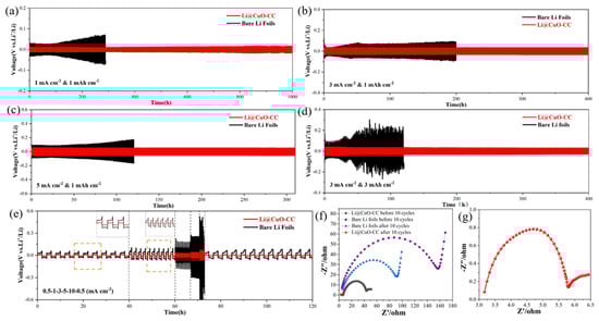
Figure 3.
Electrochemical performance of Li@CuO−CC (red) and bare Li foils (black) electrodes in the symmetrical cell. Galvanostatic cycling performance with a stripping/plating capacity of 1 mAh cm−2 at (a) 1, (b) 3, and (c) 5 mA cm−2. (d) Galvanostatic cycling performance with a stripping/plating capacity of 3 mAh cm−2 at 3 mA cm−2. (e) Rate performance at current densities from 0.5 to 10 mA cm−2. (f) Nyquist plots of the symmetrical cell based on Li@CuO−CC and bare Li electrodes before and after 10 cycles at 1 mA cm−2 for 1 mAh cm−2. (g) Nyquist plots of the Li@CuO−CC symmetrical cell after 10 cycles at 1 mA cm−2 for 1 mAh cm−2.
In order to deeply understand the cycling performance of the Li@CuO−CC electrode, SEM characterization was conducted to observe its morphology after 10 and 50 cycles. As shown in Figure 4a–c, no mossy or dendritic Li was observed on the Li@CuO−CC electrode after 10 cycles, and Li balls could be observed clearly. The spherical Li originated from the insufficient driving force that overcame the activation energy for Li crystallization. With prolonging the cycling to 50 cycles (Figure 4d–f), the surface of the Li@CuO−CC electrode could still maintain a flat and dense morphology without any observable dendrites, but Li crystal grains were anchored on the framework. As a result, the Li@CuO−CC electrode showed superior electrochemical performance and maintained structural stability even after a long time.
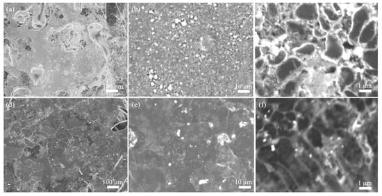
Figure 4.
SEM images of the Li@CuO−CC electrode at 1 mA cm−2 for 1 mAh cm−2 (a–c) after 10 cycles and (d–f) after 50 cycles.
A performance comparison of different lithiophilic metal oxides-CC and other CuO-modified electrodes for LMA is given in Table 1. The Li@CuO−CC symmetrical cell in this work apparently exhibited the lowest overpotential and outstanding cycling stability. The remarkable performance could be attributed to the following reasons: First of all, the lithiophilic CuO nanorod array as well as the formed Li2CuO2 with high Li ionic diffusion could regulate Li-ion flux and promote charge transfer for the Li/Li-ion redox reaction, resulting in homogeneous Li deposition without dendrites. Secondly, the carbon fibers inside the Li@CuO−CC electrode constituted good conductive networks and acted as a framework, which could reduce the local current density and accommodate the repeated stripping/plating of Li. Finally, the large voids inside CC could accommodate the deposited Li and restrain the volume expansion.

Table 1.
Comparisons of electrochemical performance of various lithiophilic metal oxides-CC and other CuO-modified electrodes for LMA.
To investigate the morphology evolution of the Li@CuO−CC electrode during the stripping/plating process, SEM images were captured with different capacities at 1 mA cm−2. During the Li stripping process, more carbon fibers were exposed in the visual field, and the CuO nanorod arrays became obvious gradually along with the increased capacity from 2 to 30 mAh cm−2 (Figure 5a–d). The CC structure could remain unchanged and keep intact even at the large stripping capacity of 30 mAh cm−2, which indicated that the CuO−CC framework host had high stability and flexibility. After stripping 30 mAh cm−2 of Li, Li re-plating with the capacity increasing from 2 to 30 mAh cm−2 was performed (Figure 5e–h). When the plating capacity was less than 10 mAh cm−2, deposited Li gradually covered the surface of CuO−CC nanorod arrays, while a few depositions spread into the internal gap of carbon fibers. At the high Li plating capacity of 30 mAh cm−2, the space between carbon fibers was covered by deposited Li, the surface without dendrite growth became flat, and the nanostructure was completely covered. The uniformly distributed CuO nanorod arrays were regarded as effective inductive agents of Li-ion nucleation, leading to homogeneous Li deposition. Simultaneously, cross-sectional view images were used to estimate the thickness variations of the Li@CuO−CC electrode at different Li stripping/plating processes. The thickness of this electrode was kept at 445 and 444 μm with stripping capacities of 2 and 10 mAh cm−2 (Figure 5a,b), in good consistent with the thickness of the pristine Li@CuO−CC electrode. With increased Li stripping capacity to 20 mAh cm−2, the thickness of the electrode decreased to approximately 421 μm (Figure 5c). With a further increase to 30 mAh cm−2, most of the carbon fibers were exposed from the Li encapsulation, and the thickness changed to 391 μm (Figure 5d), in good consistency with the thickness of the electrode after plating the 2 mAh cm−2 Li (Figure 5e). After all the stripped Li (30 mAh cm−2) was replated (Figure 5h), the thickness was the same as the original Li@CuO−CC electrode, namely, 446 μm, indicating that the Li refilled entirely the interior of the electrode. The morphological evolution illustrated that the Li@CuO−CC electrode could effectively remit the volume change and dendrite formation.
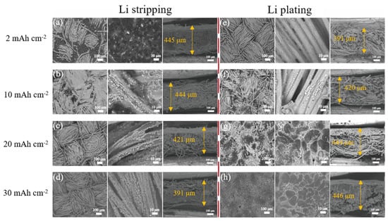
Figure 5.
Top-view and cross-sectional SEM images of the Li@CuO−CC electrode at 1 mA cm−2 with a Li stripping capacity of (a) 2 mAh cm−2, (b) 10 mAh cm−2, (c) 20 mAh cm−2, and (d) 30 mAh cm−2, and then plating of (e) 2 mAh cm−2, (f) 10 mAh cm−2, (g) 20 mAh cm−2, and (h) 30 mAh cm−2.
3.3. Electrochemical Performance of Full Cell with Li@CuO−CC Electrode
To further evaluate the practical application possibility of the Li@CuO−CC electrode, the full cell was assembled utilizing commercial LFP as the cathode and Li@CuO−CC as the anode (denoted as LFP//Li@CuO−CC). The full cell constituted of bare Li foil and LFP was listed as a contrast (denoted as LFP//Bare Li). Figure 6a displays the cycling performance at a current density of 1 C. It was not difficult to find that the LFP//Li@CuO−CC had excellent cycling stability, delivering an initial discharge-specific capacity of 133.8 mAh g−1 with an initial CE of 99.6%. The discharge-specific capacity still maintained 105.2 mAh g−1 with a capacity retention of around 78.6% and a high CE of over 99.5% at the 600th cycle. In sharp contrast, the CE of LFP//bare Li had huge fluctuations after 200 cycles, and the capacity exhibited an unstable tendency from 107.2 to 9.3 mAh g−1 at the 600th cycle. The degenerative results indicated that the LFP//bare Li had a lower Li utilization ratio during cycles. As shown in Figure 6b, compared with the LFP//bare Li (127.7, 105.9, 43, 9.3, and 0.6 mAh g−1), the LFP//Li@CuO−CC exhibited improved rates of performance of 142.1, 132.9, 115.6, 109.1, and 100.5 mAh g−1 at current densities of 0.5, 1, 2, 3, and 4 C, respectively. Figure 6c,d gives the voltage profiles at different current densities. Obviously, the Li@CuO−CC electrode showed stable charging/discharging plateaus and lower values of polarizing voltage relative to the bare Li as the test current gradually increased, which could be ascribed to the faster charge-transfer behavior of the Li/electrolyte interface. To better understand the superior cycling performance of the Li@CuO−CC electrode, the morphology after 600 cycles at 1 C was investigated (Figure 6e–g). The Li@CuO−CC displayed a dense surface without the occurrence of pulverization and obvious thickness change. This proved that the Li@CuO−CC electrode could maintain a uniform Li striping/plating and efficiently inhibit the volume expansion of Li within a full cell even after long cycles. The above results absolutely confirmed that the Li@CuO−CC electrode had improved cycling stability and rate performance, thus suggesting its practical feasibility for high-energy Li metal batteries.
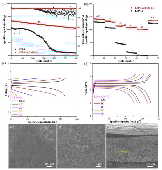
Figure 6.
Electrochemical performance of full cell constructed by LFP//Li@CuO−CC and LFP//bare Li. (a) Long cycling stability at the current density of 1 C. (b) Rate capability at various rates from 0.5 to 4 C. Charge/discharge profiles of (c) LFP//Li@CuO−CC and (d) LFP//bare Li at various current densities from 0.5 to 4 C. (e–g) Top-view and cross-sectional SEM images of Li@CuO−CC paired with the LFP cathode after 600 cycles.
4. Conclusions
In summary, the novel 3D CuO−CC composite is successfully fabricated and employed as a framework host for LMA. The whole CuO−CC framework is spontaneously injected with molten Li for less than 10 s. Its superb lithiophilicity results from the generated Li2CuO2 compounds during the thermal infusion process. Moreover, the vertically-aligned nanorod arrays can provide the capillary effect, which is beneficial to Li-infusion. The CuO nanorod arrays provide effective active sites for nucleation and the uniform growth of Li. Moreover, 3D structures of the carbon skeleton offer enough free space for volume variation and homogenize Li-ion flux distribution. Such a 3D Li@CuO−CC electrode exhibits smaller voltage hysteresis and enhanced stability in symmetrical cell tests compared with the bare Li electrode. When paired with the LFP cathode, the achieved LFP//Li@CuO−CC cell shows a stable cycling ability and excellent rate capability. It is believed that the rational design of pre-storing the Li host will shed new light on the dendrite-free LMA.
Author Contributions
K.W. and D.L. (Dongwei Li) designed the scheme and wrote the paper. K.W. performed the experiments and analyzed the results. D.L. (Derong Liu), P.Y., H.G., X.J. and M.G. contributed to the related discussions. All authors have read and agreed to the published version of the manuscript.
Funding
This research was funded by the Natural Science Foundation of Shandong Province (ZR2020QB069, ZR2022ME051), the Scientific and Technological Innovation Ability Improvement Project of Minor Enterprises in Shandong Province (2022TSGC1021), the Major Scientific and Technological Innovation Project of Shandong (2020CXGC010309), and the Major Innovation Projects for Integrating Science, Education, and Industry of Qilu University of Technology (Shandong Academy of Sciences) (2022JBZ01-07).
Data Availability Statement
Not applicable.
Conflicts of Interest
The authors declare no conflict of interest.
References
- Winter, M.; Barnett, B.; Xu, K. Before Li ion batteries. Chem. Rev. 2018, 118, 11433–11456. [Google Scholar] [CrossRef] [PubMed]
- Callegari, D.; Colombi, S.; Nitti, A.; Simari, C.; Nicotera, I.; Ferrara, C.; Mustarelli, P.; Pasini, D.; Quartarone, E. Autonomous self-healing strategy for stable sodium-ion battery: A case study of black phosphorus anodes. ACS Appl. Mater. Interfaces 2021, 13, 13170–13182. [Google Scholar] [CrossRef] [PubMed]
- Cheng, X.B.; Zhang, R.; Zhao, C.Z.; Zhang, Q. Toward safe lithium metal anode in rechargeable batteries: A review. Chem. Rev. 2017, 117, 10403–10473. [Google Scholar] [CrossRef] [PubMed]
- Li, D.; Hu, H.; Chen, B.; Lai, W.Y. Advanced current collector materials for high-performance lithium metal anodes. Small 2022, 18, 2200010. [Google Scholar] [CrossRef]
- Chen, Q.; Gong, Y.J. Applications and challenges of 2D materials in lithium metal batteries. Mater. Lab 2022, 1, 220034. [Google Scholar]
- Ke, X.; Wang, Y.; Dai, L.; Yuan, C. Cell failures of all-solid-state lithium metal batteries with inorganic solid electrolytes: Lithium dendrites. Energy Storage Mater. 2020, 33, 309–328. [Google Scholar] [CrossRef]
- Kaskel, S.; Zhang, Q.; Sun, X.L. Lithium metal anode: Processing and interface engineering. Batter. Supercaps 2021, 4, 690–691. [Google Scholar] [CrossRef]
- Yang, H.; Li, J.; Sun, Z.; Fang, R.; Wang, D.W.; He, K.; Cheng, H.-M.; Li, F. Reliable liquid electrolytes for lithium metal batteries. Energy Storage Mater. 2020, 30, 113–129. [Google Scholar] [CrossRef]
- Liu, W.; Liu, P.; Mitlin, D. Review of emerging concepts in SEI analysis and artificial SEI membranes for lithium, sodium, and potassium metal battery anodes. Adv. Energy Mater. 2020, 10, 2002297. [Google Scholar] [CrossRef]
- Cheng, X.B.; Zhao, C.Z.; Yao, Y.X.; Liu, H.; Zhang, Q. Recent advances in energy chemistry between solid-state electrolyte and safe lithium-metal anodes. Chem 2019, 5, 74–96. [Google Scholar] [CrossRef]
- Davino, S.; Callegari, D.; Pasini, D.; Thomas, M.; Nicotera, I.; Bonizzoni, S.; Mustarelli, P.; Quartarone, E. Cross-linked gel electrolytes with self-healing functionalities for smart lithium batteries. ACS Appl. Mater. Interfaces 2022, 14, 51941–51953. [Google Scholar] [CrossRef] [PubMed]
- Li, D.; Chen, B.; Hu, H.; Lai, W.Y. Constructing 3D porous current collectors for stable and dendrite-free lithium metal anodes. Adv. Sustain. Syst. 2022, 6, 2200010. [Google Scholar] [CrossRef]
- Park, S.; Jin, H.J.; Yun, Y.S. Advances in the design of 3D-structured electrode materials for lithium-metal anodes. Adv. Mater. 2020, 32, 2002193. [Google Scholar] [CrossRef] [PubMed]
- Lyu, T.; Luo, F.; Wang, D.; Bu, L.; Tao, L.; Zheng, Z. Carbon/lithium composite anode for advanced lithium metal batteries: Design, progress, in situ characterization, and perspectives. Adv. Energy Mater. 2022, 12, 2201493. [Google Scholar] [CrossRef]
- Ma, X.X.; Chen, X.; Bai, Y.K.; Shen, X.; Zhang, R.; Zhang, Q. The defect chemistry of carbon frameworks for regulating the lithium nucleation and growth behaviors in lithium metal anodes. Small 2021, 17, 2007142. [Google Scholar] [CrossRef]
- Liu, A.; Liu, T.F.; Yuan, H.D.; Wang, Y.; Liu, Y.J.; Luo, J.M.; Nai, J.W.; Tao, X.Y. A review of biomass-derived carbon materials for lithium metal anodes. New Carbon Mater. 2022, 37, 658–674. [Google Scholar] [CrossRef]
- Ji, X.; Liu, D.Y.; Prendiville, D.G.; Zhang, Y.; Liu, X.; Stucky, G.D. Spatially heterogeneous carbon-fiber papers as surface dendrite-free current collectors for lithium deposition. Nano Today 2012, 7, 10–20. [Google Scholar] [CrossRef]
- Yan, K.; Lu, Z.; Lee, H.W.; Xiong, F.; Hsu, P.C.; Li, Y.; Zhao, J.; Chu, S.; Cui, Y. Selective deposition and stable encapsulation of lithium through heterogeneous seeded growth. Nat. Energy 2016, 1, 16010. [Google Scholar] [CrossRef]
- Lin, D.; Liu, Y.; Liang, Z.; Lee, H.-W.; Sun, J.; Wang, H.; Yan, K.; Xie, J.; Cui, Y. Layered reduced graphene oxide with nanoscale interlayer gaps as a stable host for lithium metal anodes. Nat. Nanotech. 2016, 11, 626–632. [Google Scholar] [CrossRef]
- Zhang, R.; Li, Y.; Wang, M.; Li, D.; Zhou, J.; Xie, L.; Wang, T.; Tian, W.; Zhai, Y.J.; Gong, H.; et al. Super-assembled hierarchical CoO nanosheets-Cu foam composites as multi-level hosts for high-performance lithium metal anodes. Small 2021, 17, 2101301. [Google Scholar] [CrossRef]
- Xia, S.; Guo, Q.; Yu, Y.; Li, Y.; Wang, S.; Dong, D.; Liu, Z.; Zhou, H.; Zhou, X.; Liu, Z. Surface modification of carbon fiber cloth with graphene oxide through an electrophoresis method for lithium metal anode. Carbon 2023, 203, 743–752. [Google Scholar] [CrossRef]
- Feng, Y.; Zhang, C.; Li, B.; Xiong, S.; Song, J. Low-volume-change, dendrite-free lithium metal anodes enabled by lithophilic 3D matrix with LiF-enriched surface. J. Mater. Chem. A 2019, 7, 6090–6098. [Google Scholar] [CrossRef]
- Zhou, Y.; Han, Y.; Zhang, H.T.; Sui, D.; Sun, Z.H.; Xiao, P.S.; Wang, X.T.; Ma, Y.F.; Chen, Y.S. A carbon cloth-based lithium composite anode for high- performance lithium metal batteries. Energy Storage Mater. 2018, 14, 222–229. [Google Scholar] [CrossRef]
- Zhang, S.; Xiao, S.; Li, D.; Liao, J.; Ji, F.; Liu, H.; Ci, L. Commercial carbon cloth: An emerging substrate for practical lithium metal batteries. Energy Storage Mater. 2022, 48, 172–190. [Google Scholar] [CrossRef]
- Liu, F.F.; Xu, R.; Hu, Z.X.; Ye, S.F.; Zeng, S.F.; Yao, Y.; Li, S.Q.; Yu, Y. Regulating lithium nucleation via CNTs modifying carbon cloth film for stable Li metal anode. Small 2019, 15, 1803734. [Google Scholar] [CrossRef]
- Hou, Z.; Yu, Y.; Wang, W.; Zhao, X.; Di, Q.; Chen, Q.; Chen, W.; Liu, Y.; Quan, Z. Lithiophilic Ag nanoparticle layer on Cu current collector toward stable Li metal anode. ACS Appl. Mater. Interfaces 2019, 11, 8148–8154. [Google Scholar] [CrossRef]
- Pu, J.; Li, J.; Shen, Z.; Zhong, C.; Liu, J.; Ma, H.; Zhu, J.; Zhang, H.; Braun, P.V. Interlayer lithium plating in Au nanoparticles pillared reduced graphene oxide for lithium metal anodes. Adv. Funct. Mater. 2018, 28, 1804133. [Google Scholar] [CrossRef]
- Chen, L.; Chen, G.; Tang, W.; Wang, H.; Chen, F.; Liu, X.; Ma, R. A robust and lithiophilic three-dimension framework of CoO nanorod arrays on carbon cloth for cycling-stable lithium metal anodes. Mater. Today Energy 2020, 18, 100520. [Google Scholar]
- Wang, M.; Cheng, X.; Cao, T.; Niu, J.; Wu, R.; Liu, X.; Zhang, Y. Constructing ultrathin TiO2 protection layers via atomic layer deposition for stable lithium metal anode cycling. J. Alloys Compd. 2021, 865, 158748. [Google Scholar] [CrossRef]
- Jin, D.; Hu, K.; Hou, R.; Shang, H.; Wang, X.; Ding, Y.; Yan, Y.; Lin, H.; Rui, K.; Zhu, J. Vertical nanoarrays with lithiophilic sites suppress the growth of lithium dendrites for ultrastable lithium metal batteries. Chem. Eng. J. 2021, 405, 126808. [Google Scholar] [CrossRef]
- Zhang, C.; Lv, W.; Zhou, G.; Huang, Z.; Zhang, Y.; Lyu, R.; Wu, H.; Yun, Q.; Kang, F.; Yang, Q.H. Vertically aligned lithiophilic CuO nanosheets on a Cu collector to stabilize lithium deposition for lithium metal batteries. Adv. Energy Mater. 2018, 8, 1703404. [Google Scholar] [CrossRef]
- Huang, K.; Li, Z.; Xu, Q.; Liu, H.; Li, H.; Wang, Y. Lithiophilic CuO nanoflowers on Ti-mesh inducing lithium lateral plating enabling stable lithium-metal anodes with ultrahigh rates and ultralong cycle life. Adv. Energy Mater. 2019, 9, 1900853. [Google Scholar] [CrossRef]
- Wei, L.; Li, L.; Zhao, T.; Zhang, N.; Zhao, Y.; Wu, F.; Chen, R. MOF-derived lithiophilic CuO nanorod arrays for stable lithium metal anodes. Nanoscale 2020, 12, 9416–9422. [Google Scholar] [CrossRef]
- Cao, J.; Deng, L.; Wang, X.; Li, W.; Xie, Y.; Zhang, J.; Cheng, S. Stable lithium metal anode achieved by in situ grown CuO nanowire arrays on Cu foam. Energy Fuels 2020, 34, 7684–7691. [Google Scholar] [CrossRef]
- Kim, J.; Kang, S.; Lim, J.; Kim, W.Y. Study of Li adsorption on graphdiyne using hybrid DFT calculations. ACS Appl. Mater. Interfaces 2019, 11, 2677–2683. [Google Scholar] [CrossRef]
- Xu, B.; Meng, S. Factors affecting Li mobility in spinel LiMn2O4—A first-principles study by GGA and GGA+U methods. J. Power Sources 2010, 195, 4971–4976. [Google Scholar] [CrossRef]
- Gu, Z.Q.; Li, G.J.; Hussain, N.; Tian, B.B.; Shi, Y.M. 3D freestanding CuO@Copper foam as an anode for potassium ion batteries. Appl. Surf. Sci. 2022, 592, 153323. [Google Scholar] [CrossRef]
- Cheng, S.; Gao, X.; DelaCruz, S.; Chen, C.; Tang, Z.; Shi, T.; Carraro, C.; Maboudian, R. In situ formation of metal–organic framework derived CuO polyhedrons on carbon cloth for highly sensitive non-enzymatic glucose sensing. J. Mater. Chem. B 2019, 7, 4990–4996. [Google Scholar] [CrossRef]
- Guo, W.; Liu, T.; Huang, L.; Zhang, H.; Zhou, Q.; Zeng, W. HMT assisted hydrothermal synthesis of various ZnO nanostructures: Structure, growth and gas sensor properties. Physica E 2011, 44, 680–685. [Google Scholar] [CrossRef]
- Kordatos, A.; Kuganathan, N.; Kelaidis, N.; Iyngaran, P.; Chroneos, A. Defects and lithium migration in Li2CuO2. Sci. Rep. 2018, 8, 6754. [Google Scholar] [CrossRef]
- Luo, L.; Li, J.Y.; Yaghoobnejad, A.H.; Manthiram, A. A 3D lithiophilic Mo2N-modified carbon nanofiber architecture for dendrite-free lithium-metal anodes in a full cell. Adv. Mater. 2019, 31, 1904537. [Google Scholar] [CrossRef]
- Xu, R.; Cheng, X.B.; Yan, C.; Zhang, X.Q.; Xiao, Y.; Zhao, C.Z.; Huang, J.Q.; Zhang, Q. Artificial interphases for highly stable lithium metal anode. Matter 2019, 1, 317–344. [Google Scholar] [CrossRef]
- Yan, C.; Xu, R.; Xiao, Y.; Ding, J.F.; Xu, L.; Li, B.Q.; Huang, J.Q. Toward critical electrode/electrolyte interfaces in rechargeable batteries. Adv. Funct. Mater. 2020, 30, 1909887. [Google Scholar] [CrossRef]
- Yuan, H.; Ding, X.; Liu, T.; Nai, J.; Wang, Y.; Liu, Y.; Liu, C.; Tao, X. A review of concepts and contributions in lithium metal anode development. Mater. Today 2022, 53, 173–196. [Google Scholar] [CrossRef]
- Li, S.Y.; Liu, Q.L.; Zhou, J.J.; Pan, T.; Gao, L.N.; Zhang, W.D.; Fan, L.; Lu, Y.Y. Hierarchical Co3O4 nanofiber-carbon sheet skeleton with superior Na/Li-philic property enabling highly stable alkali metal batteries. Adv. Funct. Mater. 2019, 29, 1808847. [Google Scholar] [CrossRef]
Disclaimer/Publisher’s Note: The statements, opinions and data contained in all publications are solely those of the individual author(s) and contributor(s) and not of MDPI and/or the editor(s). MDPI and/or the editor(s) disclaim responsibility for any injury to people or property resulting from any ideas, methods, instructions or products referred to in the content. |
© 2023 by the authors. Licensee MDPI, Basel, Switzerland. This article is an open access article distributed under the terms and conditions of the Creative Commons Attribution (CC BY) license (https://creativecommons.org/licenses/by/4.0/).