1. Introduction
The increasing penetration of wind power in the power system poses a challenge to the frequency stability of the grid. On the one hand, the power stochasticity of wind power adds disturbances to the power system. On the other hand, the large-scale grid integration of wind power generation replaces conventional generating units that provide frequency regulation capability, reducing the system’s inertia constant and frequency regulation reserve capacity. Around the world, wind farms in regions with a high penetration of new energy sources present technical requirements for frequency response and regulation capability [
1,
2].
With the developmental f wind turbine technology, wind turbines can participate in the frequency regulation of the grid. Reference [
3] proposed an integrated inertia support method based on doubly fed asynchronous wind turbines, which supplement the rotating power of low-inertia power systems. A wind turbine pitch control based on the root trajectory method was proposed by [
4]. Reference [
5] proposed a nonlinear wind power model based on frequency perturbations to control the energy of wind turbines. However, there are certain shortcomings attributed to the participation of wind turbines in grid frequency regulation. Reference [
6] argues that the response performance of energy storage involved in frequency regulation is limited by the mechanical structure of the wind turbines and that excessive involvement of a wind turbine in frequency regulation poses a risk of damage to the turbine itself. Results from [
7] show that some wind energy is wasted during the frequency regulation process because the wind turbine can only use the energy stored in the rotor.
Energy storage systems are applied to wind farms to help maintain the frequency stability of the system after wind power is connected to the power system. The energy storage system has the technical characteristics of fast response, flexible control, and stable operation and is not constrained by the operating state of the wind turbine [
8,
9,
10,
11]. Reference [
12] shows that energy storage systems can respond quickly to frequency disturbances caused by new energy generation and loads under the dispatch of the power system. The research results of [
13] show that the coupled wind power and energy storage systems demonstrate complementary characteristics in the process of frequency regulation. Reference [
14] analyzed the economics of the complementary wind power and storage regulation system. The researchers of [
15] designed a virtual inertia-based energy storage operation to cope with the demand of a high percentage of new energy penetration. Therefore, energy storage is well suited to act as a supplement to frequency regulation resources in high penetration areas of wind power.
At this stage, research on the separate participation of wind turbines in frequency regulation is relatively mature. The aggregation model for wind power plants established by [
16] provides an explicit representation of the regulated power provided by the wind turbine under different operating conditions. The results of [
17] regarding the inertial response and drop characteristics show that the external characteristics of wind power can provide good support to the power system, especially in the case of frequency disturbances. At this stage, the synergistic participation of wind power and energy storage in frequency regulation is mainly directed to the capacity configuration, while the principle of action is less often studied. The researchers of [
18,
19] fixed the capacity of energy storage involved in frequency regulation from the perspective of standby power and inertial response. The researchers involved in [
20] performed collaborative energy storage planning based on frequency constraints under a high penetration of new energy sources. Reference [
21] proposed an energy storage planning technique based on a spatiotemporal model of wind power generation, which improves the overall economics of the system.
When wind power and energy storage are collaboratively involved in frequency regulation, the control technique becomes critical to the system’s operational efficiency. Reference [
1], which studied the operation mode of battery participation in frequency, showed that the method of response to different frequency disturbances affects the operating cost of energy storage. The researchers proposed a filter-based energy storage operation strategy to reduce unnecessary storage power fluctuations. However, this method simultaneously reduces the ability to respond quickly to disturbances. Reference [
22] proposed a method to adjust the sag coefficient and inertia control parameters according to the wind speed. Reference [
23] proposed a virtual inertia strategy improvement scheme based on model predictive control. These methods can effectively improve the system response performance to disturbances, but such methods require online wind prediction data for support, enhancing the methods’ application difficulty. Reference [
24] proposed a frequency regulation measurement using sliding film control and a disturbance observer to improve the regulation accuracy, which uses a higher precision system model and involves more variable parameters, limiting the application of the method in practical engineering.
This paper investigates the frequency response characteristics of the joint frequency regulation of wind power storage. A frequency response model was established, containing power, wind, and energy storage systems. The different frequency characteristics of inertia control, pitch control, and energy storage were considered. Their complementary relationships were used to achieve a fast response to frequency regulation in high-penetration areas of wind power. For the complex structure of wind power and energy storage system, this paper adopts a fuzzy PID controller to realize the adaptive control of frequency regulation. The control scheme proposed in this thesis features a simple design, adaptive adjustment, and online operation without the need for additional data. The feasibility of the theory is verified via case simulation. The paper is structured as follows.
Section 1 introduces the research background, reviews the existing research results at this stage, and summarizes the main content and structure of this paper.
Section 2 presents the components of the power system containing energy storage and wind power, including the prime mover and generator model, the frequency characteristics model, the automatic speed regulation system model, the wind power model, and the battery model. A transfer function model is used to characterize the response of each component in the frequency regulation process.
In
Section 3, the frequency regulation system is developed using the models mentioned in
Section 2, and the frequency regulation results are analyzed and compared for different combinations of frequency regulation methods. A fuzzy PID controller is used to manage the frequency regulation of the system based on the existing model.
In
Section 4, actual data are used to simulate and verify the model and control method proposed in this paper.
In
Section 5, the theoretical analysis and simulation results are summarized.
2. Frequency Response Model for Power Systems with Wind Power and Energy Storage
As the new energy power system contains several different power sources, the frequency response model of each section was the basis for studying the frequency response of the power system. This section analyzes the modeling of the components of the power system.
2.1. The Prime Mover and Generator Model
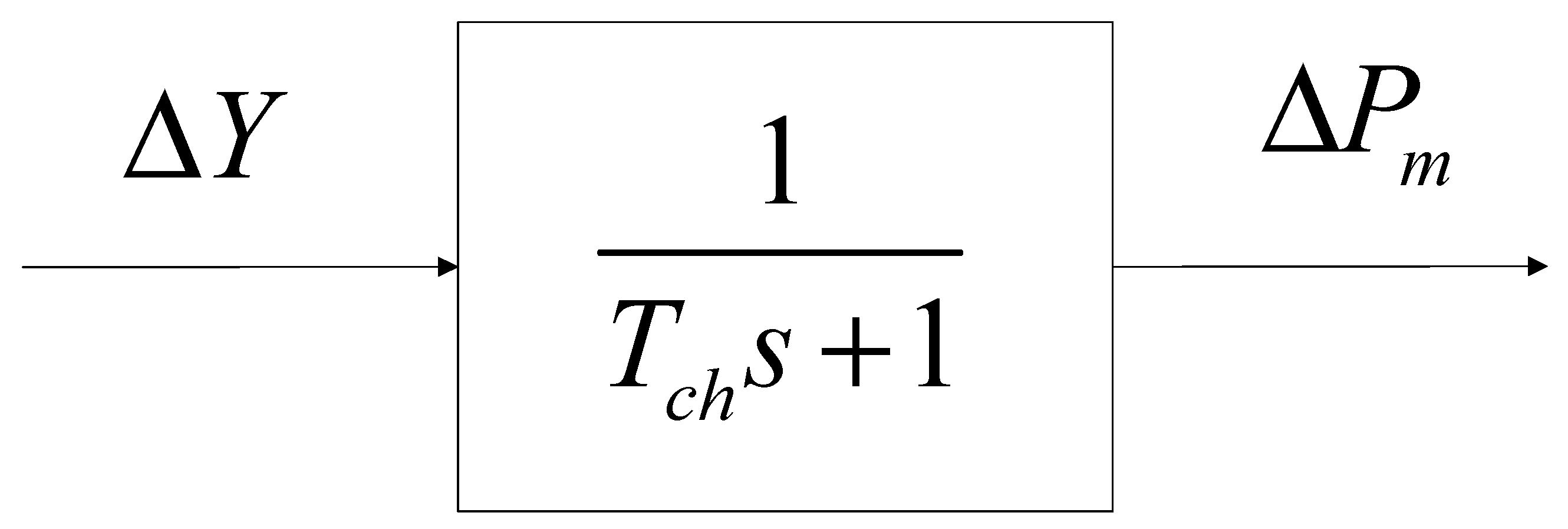
The prime mover is the energy base of the power system, and converts mechanical or thermal energy into rotational kinetic energy. The rate of change of the power system frequency is less than that of the prime mover’s power angle. The perturbation-based small signal model can effectively analyze the prime mover’s frequency response characteristics.
The prime mover is often represented in power systems by an inertial system, the structure of which is shown in the
Figure 1.
A generator is a device that converts the rotational kinetic energy provided by the prime mover into electrical energy. The rotor of a generator retains a certain amount of rotational inertia to maintain the power generated, as shown in Equation (1).
where
E is the generator rotor’s rotational power,
J is the rotational inertia of the generator rotor, and
ωm is the generator speed.
The transient process of the generator is faster than the dynamic process of the prime mover. When frequency fluctuations occur in the power system, the generator balances power by converting rotational force into electrical energy according to the following equation of state.
where,
Pm is the generator’s mechanical power, and
Pe is the generator’s electrical power.
From the above analysis, it is clear that the rotational inertia of the generator mainly influences the generator frequency fluctuations caused by the power imbalance. The inertia constant
H is defined as the ratio of the rotational kinetic energy
E to the apparent nominal power of the generator.
The dynamic relationship between frequency fluctuations and motor speed can be obtained by normalizing the difference between mechanical and electromagnetic power.
where Δ
Pg is per unit of power fluctuations and the base power is the apparent nominal power of the motor. Δ
ω is per unit of motor speed fluctuations, and the base speed is
ωs.
As the power system’s frequency and the generator’s rotational speed are positively correlated, the dynamic relationship between power fluctuations and frequency fluctuations can be obtained by replacing the per unit of the rotational speed fluctuations and frequency.
where Δ
f is per unit of rotational frequency.
The Laplace transform obtains the frequency model transfer function of the generator.
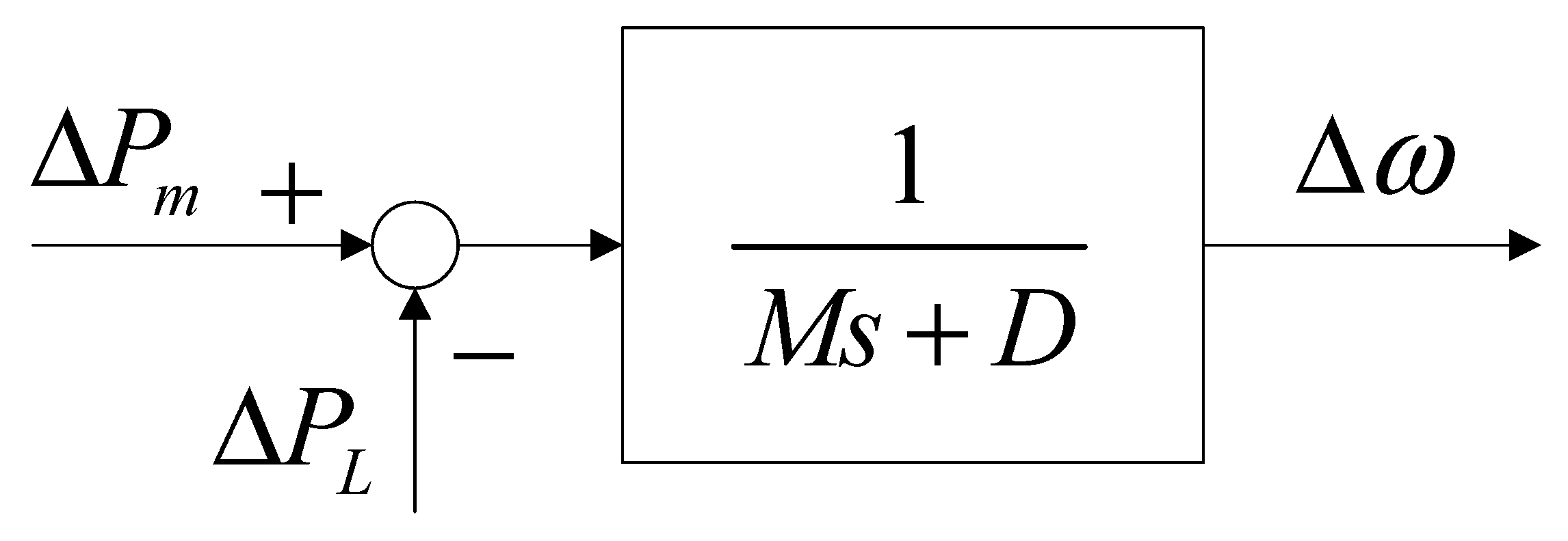
2.2. The Frequency Characteristic Model
The frequency characteristic model of a power system reflects the relationship between the system power balance and frequency fluctuations. The load frequency characteristics and generator frequency characteristics mainly influence this characteristic.
When the frequency fluctuation of the power system does not exceed a specific limit around the rated value, the load frequency characteristic can be linearized, and the characteristic curve is approximated to be a straight line.
where Δ
Pf is the per unit for change in load power affected by frequency, and
D is the load-damping factor.
When the power fluctuates, the generator’s frequency characteristics are influenced by both its characteristics and external load characteristics. The frequency characteristics of the power system can be obtained by considering the generator model and the load model in conjunction.
The Laplace transform obtains the frequency characteristic model’s frequency modulation transfer function, the structure of which is shown in the
Figure 2.
2.3. The Automatic Speed Control System Model
When the load on the power system increases, the generator output electromagnetic power becomes greater than the input mechanical power, the generator speed drops, and the power system frequency drops. The frequency detection system senses the frequency change. The governor can adjust it to open the turbine valve (or turbine water flow valve) to increase the mechanical power output of the prime mover, and making the system enter a new steady state.
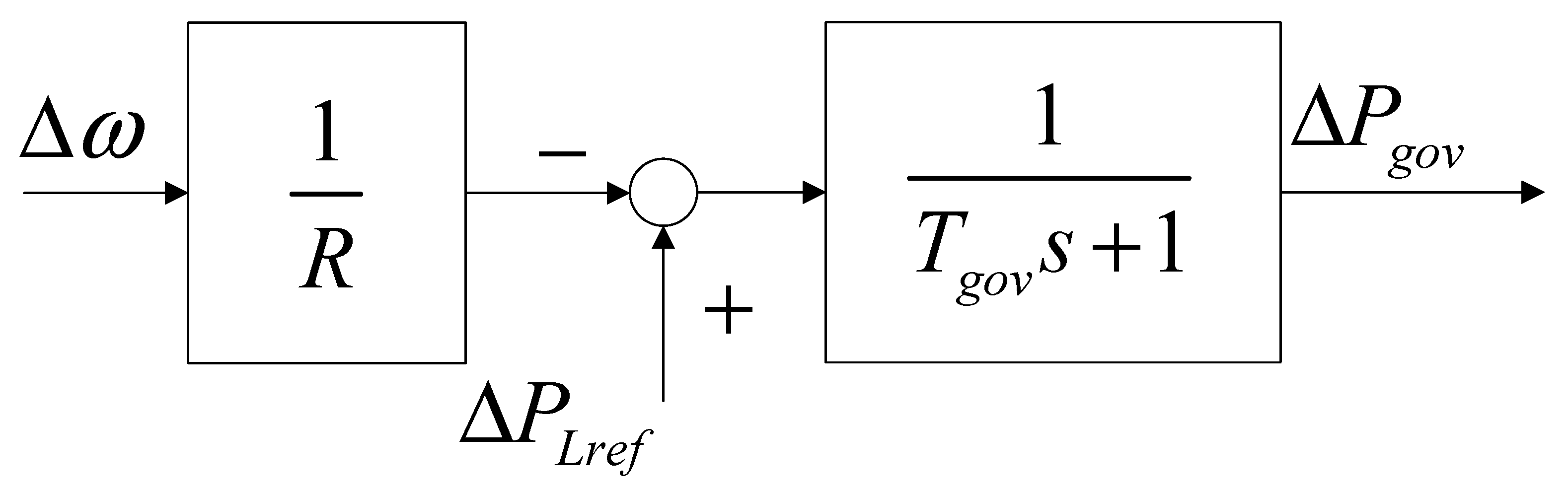
The governor uses differential speed regulation for power generation. The governor works on an engineering equivalent to a first-order inertia function. The function of the process is as follows.
where Δ
Pgov is the power increase from the governor,
PLref is the reference supply rate, and
Tgov is the inertia time constant of the governor.
R is the droop factor and the structure of which is shown in the
Figure 3.
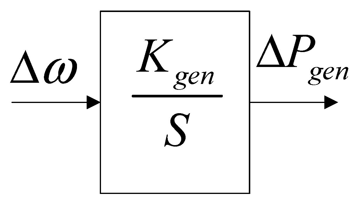
For the generator to recover under power disturbances, a frequency regulator is required for differential-free regulation. The process is equivalent to an integral, shown as follows.
where
Kgen is the frequency modulator integration constant. And the structure of which is shown in the
Figure 4.
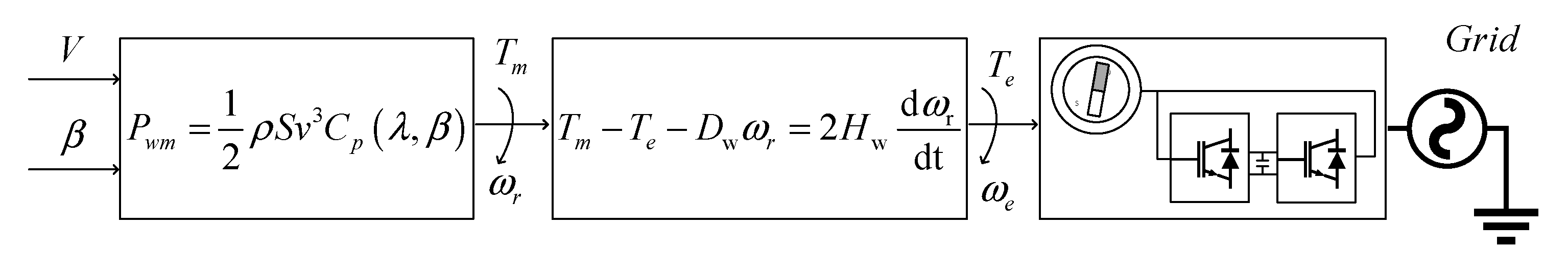
2.4. The Wind Power Model
A wind turbine is a device that converts wind energy into electrical energy. Wind energy is a form of clean energy connected to the grid in large quantities. The wind turbines capture wind energy as follows.
where
Pwm is the wind power captured,
ρ is the air density,
Sw is the area swept by the wind turbine,
v is the wind speed, and
Cp is the wind energy utilization factor. Meanwhile,
r is the radius of the wind turbine,
λ is the tip speed ratio, and
β is the pitch angle. The equation to determine the wind turbine motion rotor of a wind turbine is expressed as:
where
Tm is the wind turbine’s mechanical torque,
Te is the wind turbine’s electromagnetic torque, and
Pws is the electrical power of the turbine.
Dw is the mechanical damping factor of the wind turbine. And the structure of which is shown in the
Figure 5:
where,
Hw is the rotational constant of inertia of the wind turbine, which can be shown as follows:
where
ωr is the mechanical speed of the wind turbine,
ωe is the electrical speed of the wind turbine, and
p is the pole pair of the wind turbine.
When there is a shortfall in the wind turbine’s captured power and output power, the integration of the rotor equations of a wind turbine produces the frequency fluctuations due to power fluctuations.
where Δ
ωr is the increment of the speed from the initial moment
t0 to the end moment
t1, and
ωr,t0 and
ωr,t1 are the initial and disturbance speeds, respectively. This equation is expressed in frequency fluctuations, as shown in Equation (16).
From the above analysis, it is clear that the conversion of rotor energy via control output electromagnetic power occurs during a frequency disturbance.
When the grid frequency is subjected to a power disturbance that results in a frequency drop, the wind turbine deviates from MPPT mode, reducing the input power, which can be suppressed by decreasing the rotor rotational power when the wind turbine meets Equation (17).
Similarly, when the grid frequency rises, the wind turbine decreases the input power due to deviation from MPPT mode when the wind power participates in frequency regulation according to Equation (18).
Wind power frequency control has a smaller time scale for rotor inertia and a faster response than primary and secondary frequency control. In addition, the inertial response does not need to be left with spare power, and its duration is short (<10 s) due to speed limitations. In contrast, primary and secondary frequency modulation has extra intensity and a more extended period (tens of s to several min). Therefore, the technical characteristics of rotor inertia control for wind turbines are suitable for modeling the inertial response of conventional power supplies with the following transfer function for the frequency model.
where
kdf is the inertia response factor,
Tω is the rotor inertia response time constant, and Δ
Pω is the rotor inertia provided power.
Pitch control is the primary control strategy for wind turbines. This control strategy controls the pitch angle of the wind turbine so that the output power is in a range below the maximum power point. Pitch control has a strong regulation capability and a wide range of regulations. However, its response is relatively slow and suffers an unavoidable delay due to the mechanical characteristics. The transfer function of its regulation process is expressed as:
where
kpf is the primary frequency modulation factor,
Tβ is the pitch response time constant, and Δ
Pβ is the power provided by the pitch control.
The frequency response model of the wind farm can be obtained with the following frequency model transfer function.
2.5. Battery Model
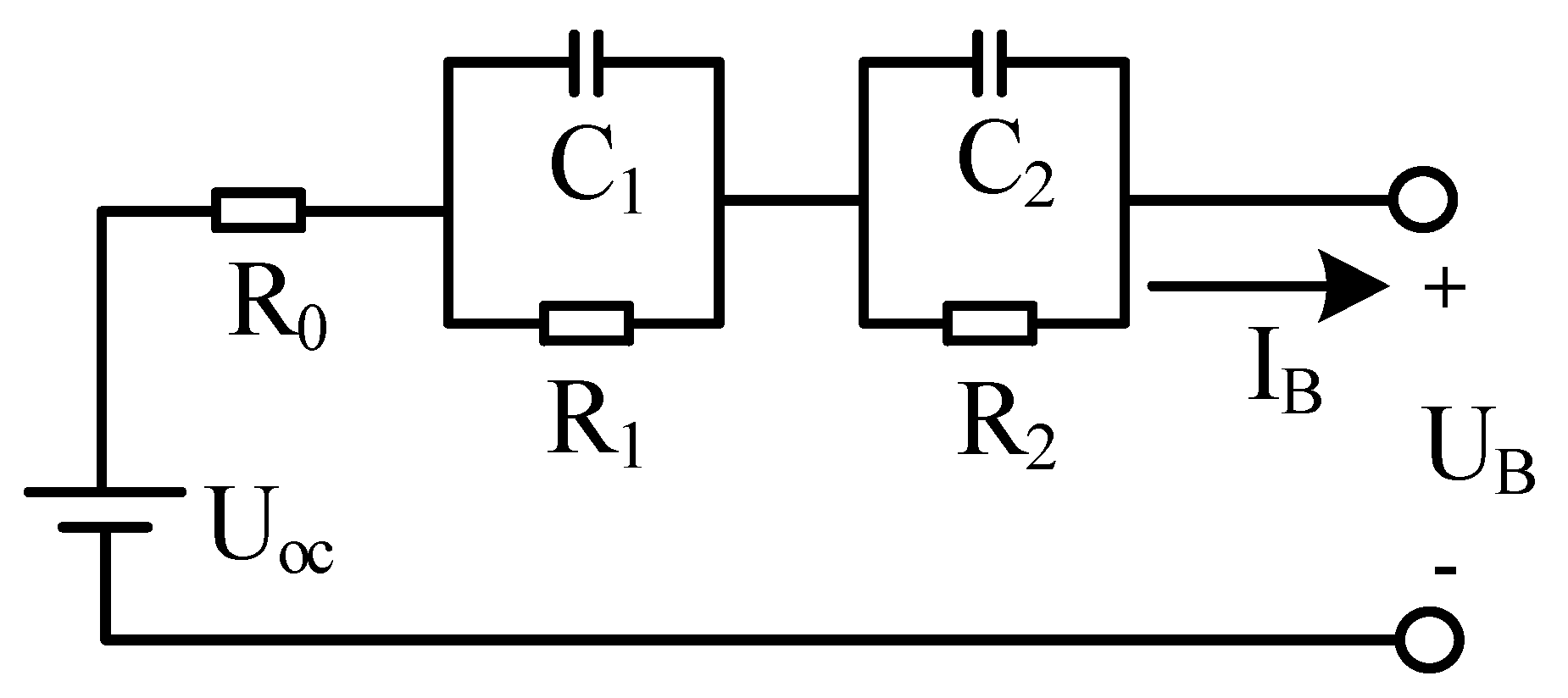
The equivalent circuit model of a battery uses electrical components such as resistors, capacitors, and voltage sources to describe its electrical characteristics. As representatives of electrochemical energy storage batteries, lithium-ion batteries are widely used in the field of frequency regulation because of their significant advantages, including high energy density, high power density, and long cycle life.
The Li-ion battery model is used to represent its operating state. For the frequency regulation application scenario, the main focus is on the battery’s responsiveness, which requires modeling both the battery itself and the energy storage power converter. The lithium battery is usually equated to a controlled voltage source excited by the external current due to its voltage source characteristics; the lithium battery is connected to the rest of the system through the storage power converter, and the storage power converter controls the current of the lithium battery.
The DP model is a Li-ion battery model that enables online model simulation. The DP model has better accuracy and applicability than other models and has superior dynamic performance shown in
Figure 6.
Where, UOC is the open circuit voltage of the battery, R0 is the battery ohmic resistance, R1 and R2 are the polarized internal resistance of the battery, C1 and C2 are the polarized capacitance of the battery, IB is the output current of the battery, and VB is the output voltage of the corresponding state.
The phenomenon where a current passes through a cell, causing the potential for it to deviate from the equilibrium potential, is called cell polarization. When the current flowing through the battery is zero, the polarization phenomenon can be ignored, and the internal polarization resistance is not voltage divided. The external characteristic voltage of the battery at this time becomes the open circuit voltage of the battery. As the current flowing through the cell increases, the external characteristic voltage of the cell gradually decreases due to the polarized internal resistance. This leads to the mathematical expression of the model as
From the analysis of the above model, it is clear that the characteristics of a battery are mainly influenced by the battery current and the polarization voltage, which is dynamically influenced by the current. When the current varies, the transfer of the two can be obtained as
where Δ
Up is the change in polarization voltage and Δ
IB is the change in battery output current. The coefficients of the transfer function are shown below.
The power control of the energy storage system is implemented to control the battery current, and the transfer function of the storage power converter is as follows.
where
TE is the energy storage response time constant, and Δ
PE is the power supplied during energy storage.
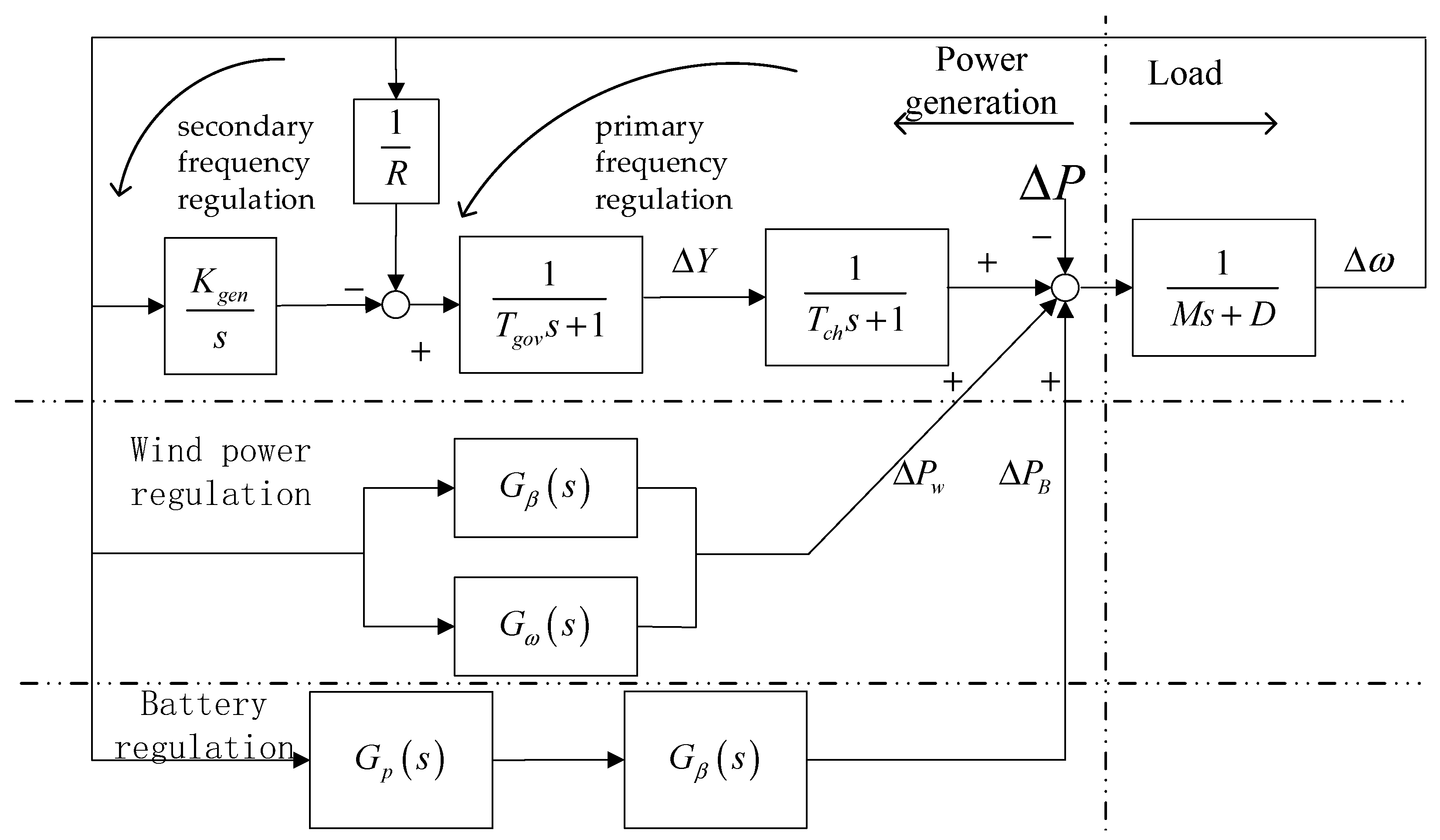
3. Structure of the Frequency Regulation System with Wind Power and Energy Storage
3.1. Structure of the Frequency Regulation
This study selected a grid-connected power system for wind power generation assisted by energy storage and frequency regulation for research. The system consisted of a prime mover, wind turbine, energy storage, and load. The structure of the system is shown in
Figure 7.
The frequency regulation model containing wind power and energy storage can be divided into primary frequency regulation, secondary frequency regulation, wind power regulation, and battery regulation. When a disturbance occurs, these regulation methods can be regulated individually or in combination.
The prime mover uses a speed governor and a frequency regulator to complete primary and secondary frequency regulation, respectively. Wind turbines rely on their mechanical properties to participate in frequency regulation. The equivalent inertia constant of the system and its transfer function are expressed as follows.
where
η is the wind power penetration rate,
M0 is the inertia of the power system without wind turbines, and
Mη is the inertia of the system at the corresponding penetration rate.
The disturbance in this power system consisted of two aspects. On the one hand, the disturbance was caused by the difference between the actual load and the output plan; on the other hand, the disturbance was caused by the stochastic nature of wind power generation.
3.2. Response Characteristics of Frequency Regulation
Based on the frequency characteristics model of the above components, the frequency characteristics model of the power system was established based on the participation of each component under different frequency regulation methods.
When no wind power is connected, the frequency base of the system is the prime mover group, which has the following frequency representation characteristics.
where
Gs0(
s) is the frequency response of the power system without wind power, and
GR(
s) is the frequency-modulated response of the prime mover with primary and secondary frequency modulation, which feature in Equation (29).
When wind power is not involved in frequency regulation, the prime mover regulates the system frequency. However, the equivalent inertia of the system is reduced, and the frequency regulation part of the output force is reduced; its frequency characteristic function is shown in Equation (30).
The wind power generation model shows that wind turbines can provide a specific frequency regulation capability through their mechanical characteristics. When considering the wind turbine’s frequency regulation capability, the system’s frequency response characteristics are as indicated in Equation (31).
The frequency regulation capability provided by wind turbines is limited by the mechanical characteristics and the capacity of the generator set, for which insufficient frequency regulation capability needs to be supplemented by energy storage. The frequency response characteristics of the system are as described in Equation (32)
The results for different frequency regulation models subject to load perturbations can be obtained using the final value theorem shown in Equation (33).
The above analysis shows that the system frequency deviation is related to damping characteristics, sag characteristics, and disturbance amplitude. When wind power does not participate in frequency regulation, the increase in wind power penetration causes the system’s steady-state frequency deviation to increase. When wind power participates in frequency regulation, the steady-state frequency deviation can be flexibly adjusted by controlling the frequency regulation coefficient.
3.3. Fuzzy PID Controllers for Frequency Regulation
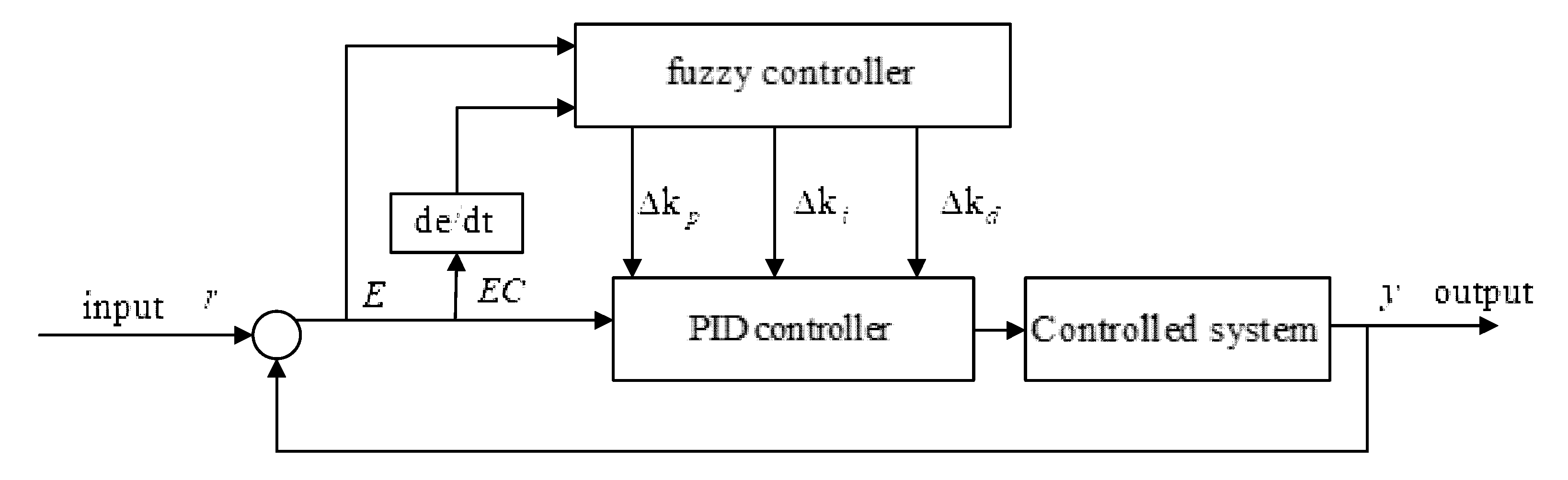
For power systems with wind power, energy storage controllers need to be designed to meet the frequency regulation needs. The frequency of a power system containing wind power and energy storage is a higher-order transfer function, and adjusting the controller parameters in this way is very complex. On the other hand, the uncertainty of wind power and the extensive use of power electronics cause the system parameters of power systems to be constantly changing and challenging to measure. Controller based on constant parameters find it difficult to cope with complex and variable frequency regulation systems.
As an intelligent inference controller, the fuzzy PID controller has a good control effect on complex frequency regulation systems, which are time-varying nonlinear systems. The structure of the fuzzy PID controller is shown in
Figure 8.
The fuzzy PID controller design was divided into steps: theoretical domain transformation, fuzzification, control rules, and regulation variables.
Ke is the quantization factor of the error,
Kec is the quantization factor of the rate of change of the error, and
Ku is the scaling factor of the output control quantity. These are related to the theoretical domain as follows.
where
n,
m, and
l are the quantitative grades of
Ke,
Kec, and
Ku, respectively; and
e(max),
ec(max), and
u(max) are the theoretical domain of the error, the theoretical domain of the rate of change of the error, and the domain of the output, respectively.
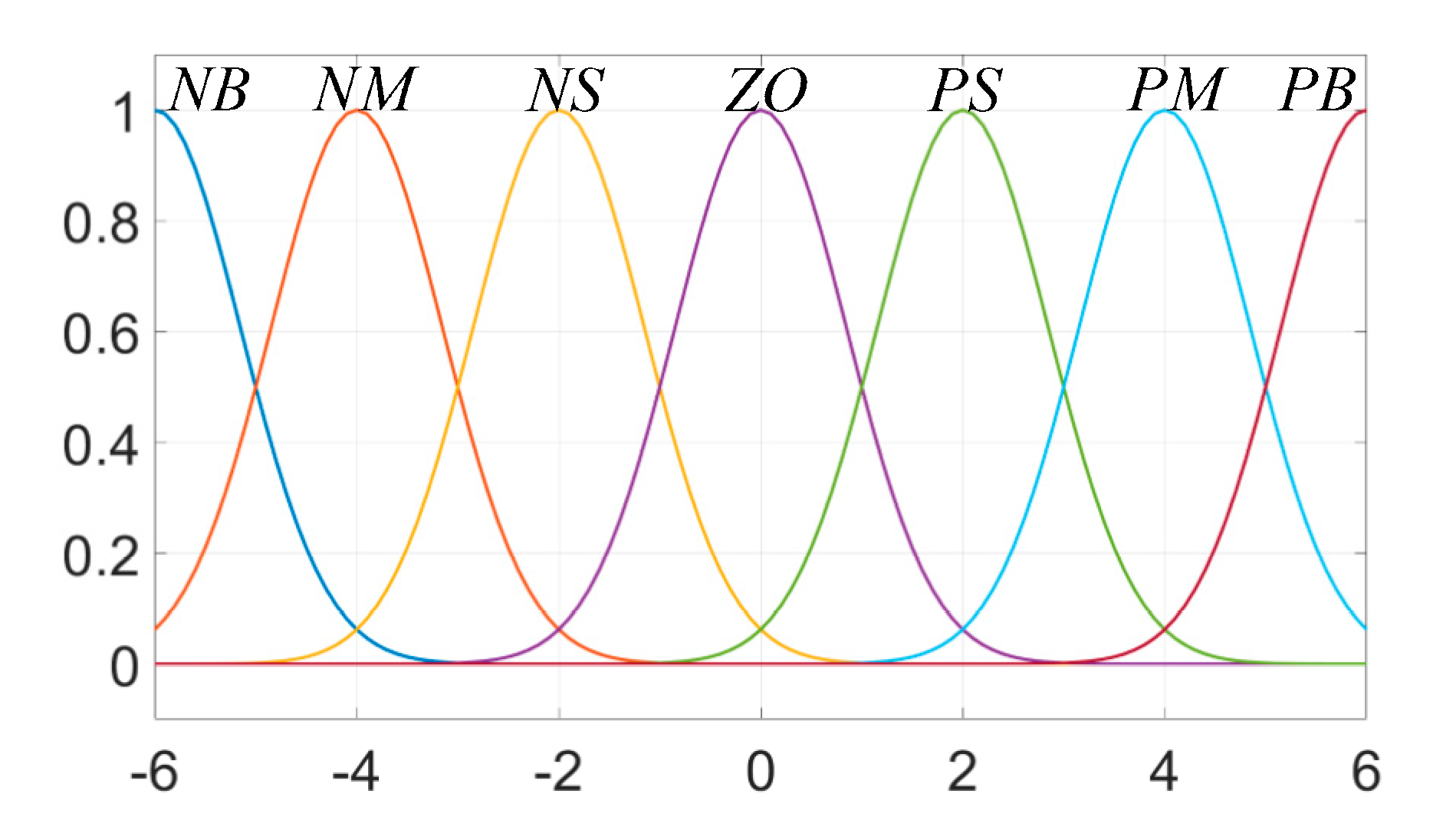
In the fuzzification process, the inputs and outputs were all Gaussian subordinate functions characterized by good smoothness. Fuzzy language variables were {NB, NM, NS, ZO, PS, PM, PB}. The affiliation function is shown in
Figure 9.
The fuzzy control rules are determined by the relationship between the inputs and outputs and the roles they play. According to the different roles played during proportional, integral, and differential regulation, the general experience of fuzzy PID frequency controller design is as follows.
(1) When the error is significant, the control system should have a better tracking ability, and to prevent the control system from appearing to have a more significant overshoot, it should take a larger proportional coefficient with a smaller differential coefficient, which at this time should be a vital link to limit, generally taking the integral coefficient to zero.
(2) When the error is moderately large, the control system should have a slight overshoot, the proportional coefficient should take a smaller value, and the value of the integral coefficient should be appropriate; the size of the differential coefficient has a more significant impact on the control results, so the differential coefficient should be appropriate.
(3) When the error is small, the control system should have good stability and prevent small oscillations in the control result. The proportional coefficient and integral coefficient should take larger values. The differential coefficient is decided according to the size of the change error rate, and when the error rate of change is significant, the differential coefficient takes a smaller value.
The fuzzy control rules determined from the general experience of frequency control systems are shown in
Table 1,
Table 2 and
Table 3 [
25].
The correction values for the PID controller control coefficients were obtained by fuzzy control and then corrected using the parameter correction formula.
where
Kp0 Ki0, and
Kd0 are the initial values of the PID controller parameters, respectively, determined by the system’s frequency response characteristics.
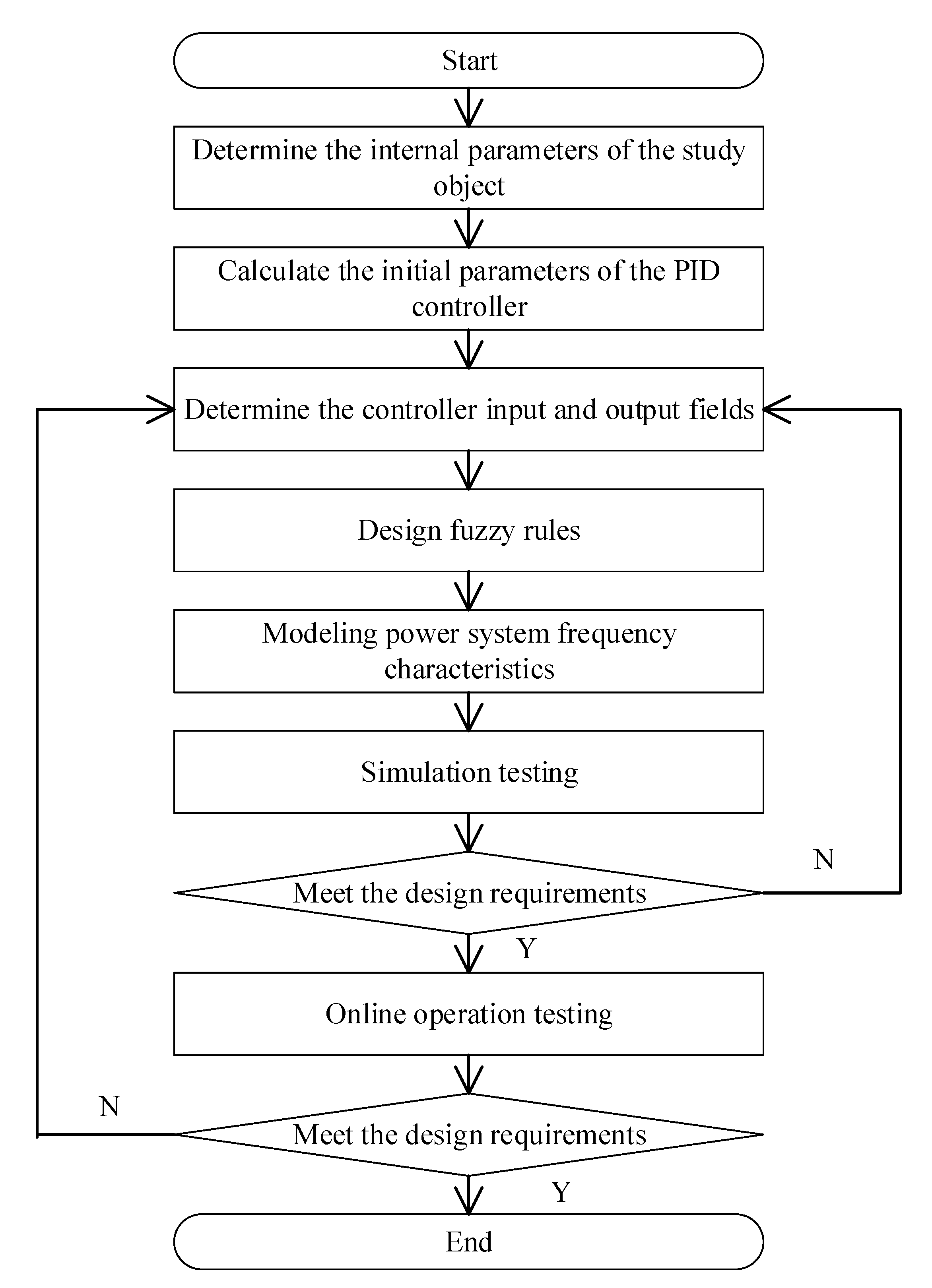
The design steps of the proposed fuzzy PID controller used in this paper are shown in
Figure 10.
Compared with other frequency regulation control strategies, the proposed fuzzy PID-based control strategy has the feature of easy parameter design and requires no high-precision modeling of the controlled system. In addition, the proposed control strategy does not require additional data, such as wind prediction data, for support during the online operation of the actual project, reducing the control strategy’s application cost. The results of comparing the characteristics of the proposed fuzzy PID control strategy with other control strategies used for frequency regulation are shown in
Table 4.
4. Case Studies and Simulations
Based on the above analysis, this paper establishes a frequency characteristic model of a power system containing thermal power, wind power, and energy storage based on MATLAB/Simulink. The energy storage is configured in a centralized way near the outlet of the wind farm and connected to the system through power electronic converters. The wind farm data used in this case study were from wind farms in North China, where the power system has a wind power penetration rate of 20%, and energy storage is configured at 10% of the wind power scale to meet the policy requirements of the wind power plant location. The time constants used were from reference [
26], and the battery data were from reference [
27]. The data used in the examples were normalized. The parameters of the case are shown in
Table 5.
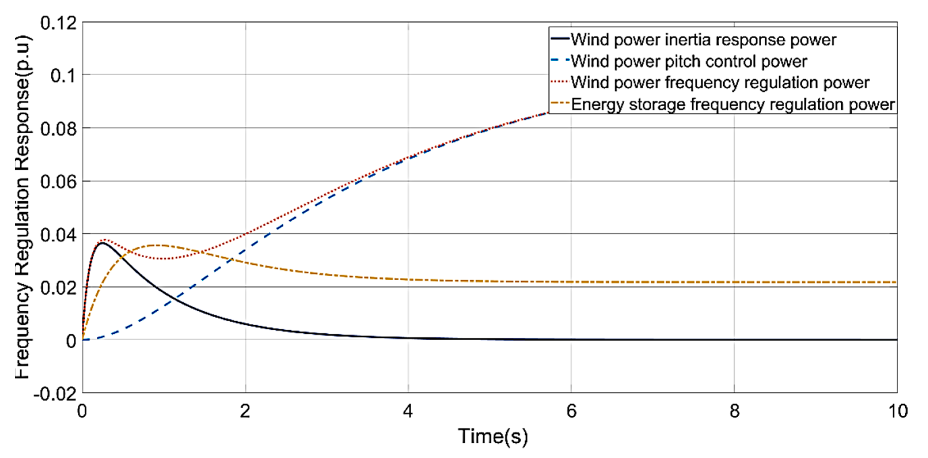
As shown in
Figure 11, the inertial response can quickly adjust the system frequency change, but the duration is limited, increasing the inertial response capability of the system, which helps to reduce the system frequency nadir and rate of change. Pitch control is affected by mechanical properties, and the response speed is slower but provides a more significant power and longer duration, providing the system’s primary frequency regulation power and reducing the system’s steady-state frequency deviation; in the transition process between the two, the wind power provides a short-term shortage of frequency regulation power, affecting the rapid recovery of the system frequency. While the response time of energy storage is based on inertial response and pitch control, the energy storage system makes up for the power shortage in the frequency regulation process with wind power, which improves the stability of wind power to cope with frequency disturbances.
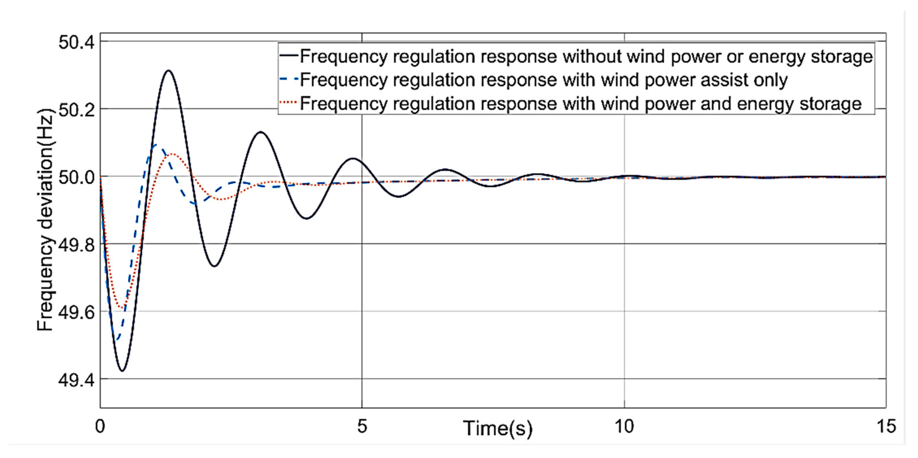
In this paper, three operation modes of wind power and energy storage participation in frequency regulation were simulated and analyzed. The changes in system frequency characteristics under the three modes are shown in the
Figure 12, and the comparison of frequency quality indicators is shown in
Table 6.
It was found that wind power participation in frequency regulation provides inertial response and frequency regulation standby capacity, which causes the lowest point of system frequency response under disturbance elevated and steady-state frequency deviation to be reduced. However, wind power participation in frequency regulation on the frequency change rate is small; the joint wind-storage frequency regulation takes advantage of the fast energy storage response to reduce steady-state frequency deviation further, enhancing the frequency nadir. At the same time, the energy storage system reduces the frequency change rate. It provides additional damping for the system frequency change, reducing the impact of frequency disturbances on system stability.
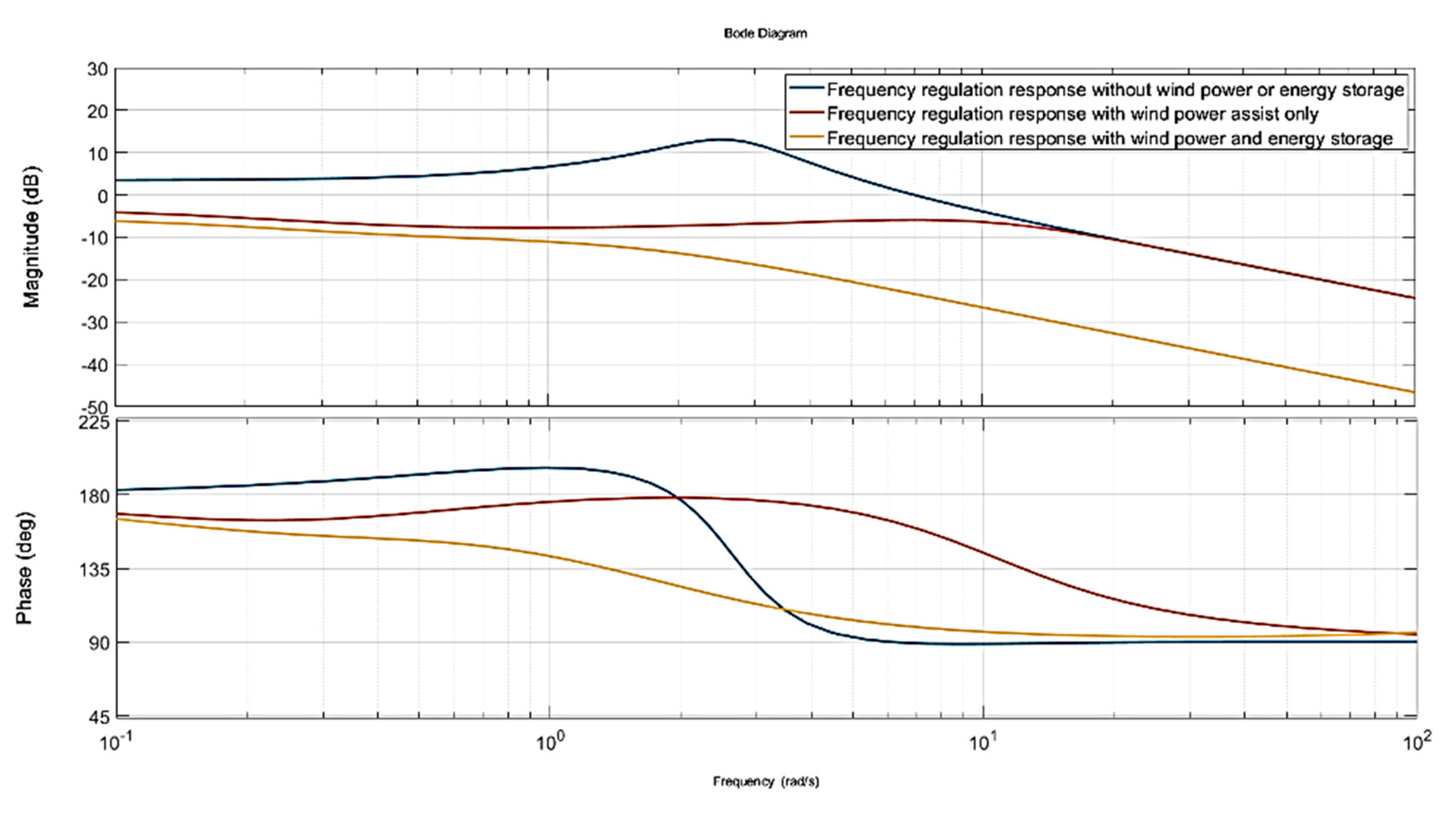
Bode diagrams of the three-frequency regulation are shown in
Figure 13. The participation of wind power and energy storage in frequency regulation can significantly improve the amplitude-frequency response gain of the power system. Wind power and energy storage can significantly suppress the disturbance gain in the frequency band below the fundamental frequency. The different regulation methods have convergent gains in the low-frequency region, indicating that the corresponding system steady-state deviation frequencies are the same. In the frequency band above the fundamental frequency, the improvement of wind power on the power system frequency disturbance gradually decreases. In contrast, the suppression of energy storage on high-frequency disturbance gradually becomes prominent. This shows that energy storage is essential to wind power frequency regulation.
The proposed fuzzy PID controller was designed based on the frequency analysis above. The proportional, integral, and differential coefficients were set to 0.5, 0.1, and 0.1, respectively. The simulation analysis results show that the proposed controller achieves the backward tracking of power disturbance and reduces the effect of power disturbance on the system frequency stability (
Figure 14).
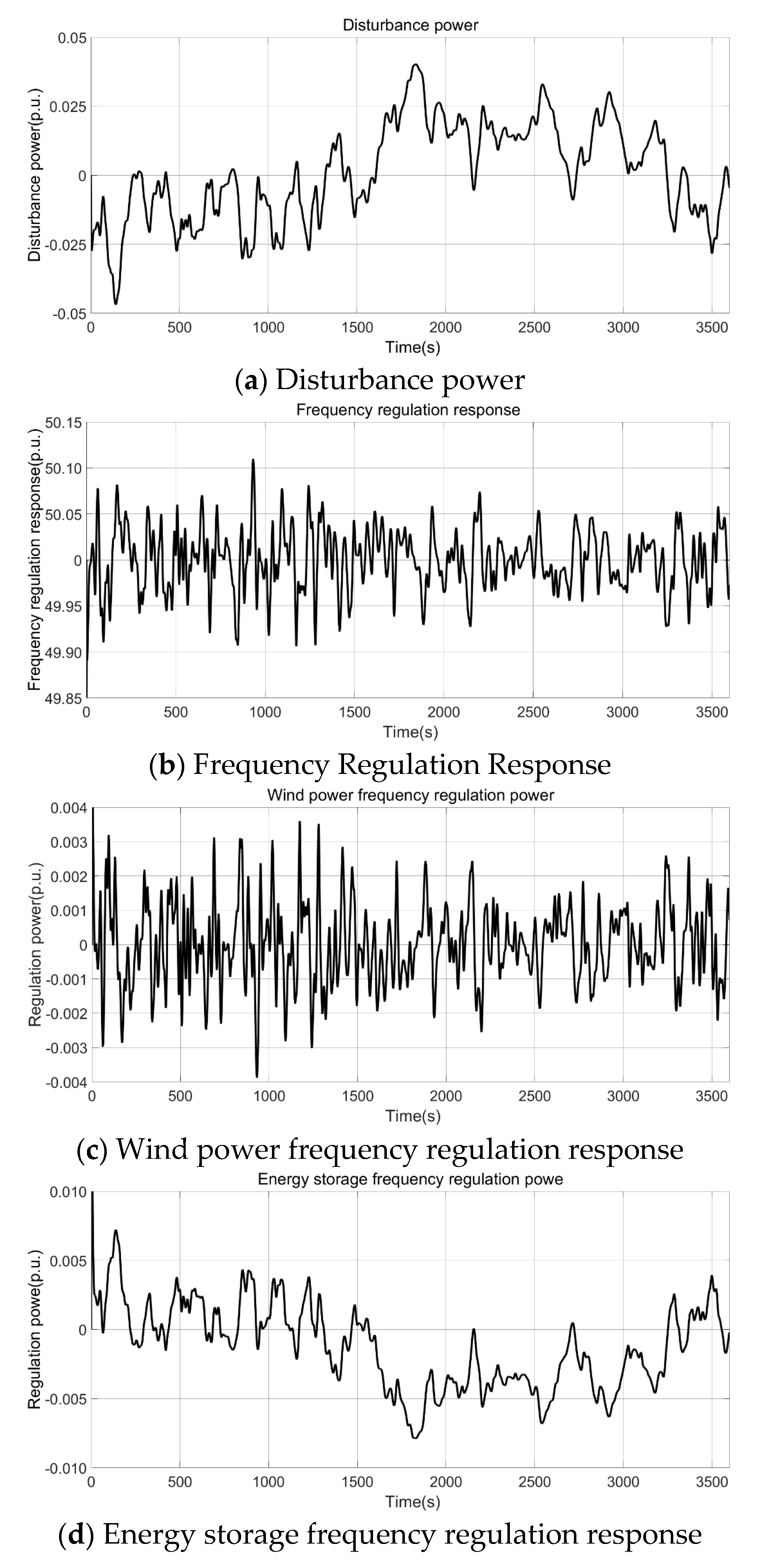
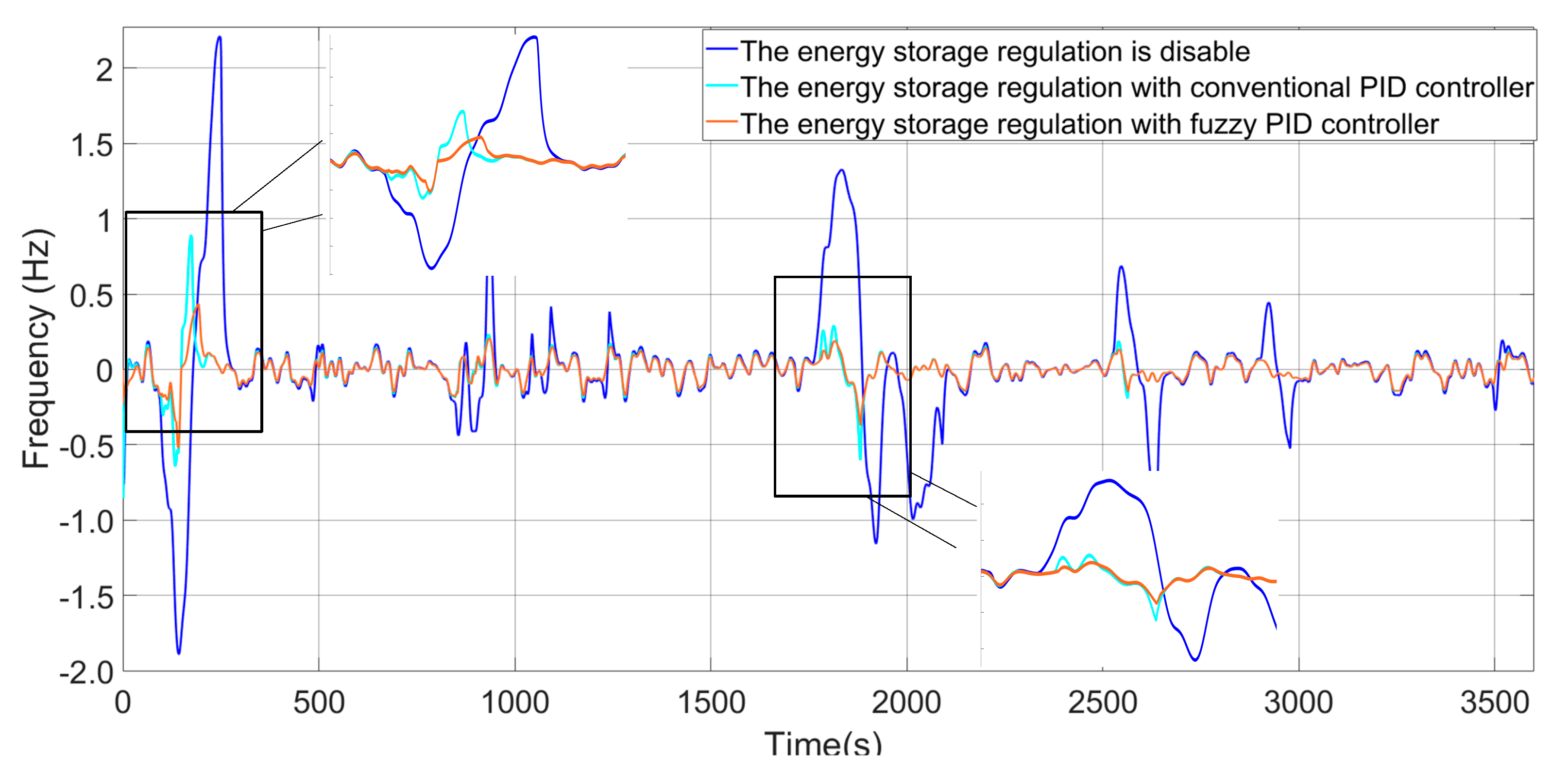
The results of the frequency regulation under strong perturbation shown in the
Figure 15, which were used for simulation to verify the effectiveness of the fuzzy PID controller proposed in this paper. The strong perturbation was added randomly in this case, in which the most significant downward perturbation occurred near 200 s of simulation, and the most significant upward perturbation occurred near 1700 s. As the results show, the fuzzy PID controller designed in this paper, due to the online adjustment of the controller parameters at the moment of solid perturbation, made the control results better than the control scheme using PID alone, and gave full play to the beneficial role of energy storage in the frequency regulation process.


