Article

Analysis of Ni-Rich Cathode Composite Electrode Performance According to the Conductive Additive Distribution for Application in Sulfide All-Solid-State Lithium-Ion Batteries

1
Department of Smart Green Technology Engineering, Pukyong National University, 45, Busan 48547, Republic of Korea
2
Department of Electrical Engineering, Chosun University, 309, Gwangju 61452, Republic of Korea
3
Department of Nanotechnology Engineering, Pukyong National University, 45, Busan 48547, Republic of Korea
*
Author to whom correspondence should be addressed.
Batteries 2023, 9(12), 590; https://doi.org/10.3390/batteries9120590
Submission received: 18 November 2023 / Revised: 6 December 2023 / Accepted: 12 December 2023 / Published: 14 December 2023

Abstract

:
All-solid-state lithium-ion batteries (ASSLBs) represent a promising breakthrough in battery technology owing to their high energy density and exceptional stability. When crafting cathode electrodes for ASSLBs, the solid electrolyte/cathode material interface is physically hindered by the specific morphology of carbon additive materials. In this paper, we examine the distribution of conductive additives within the electrode and its impact on the electrochemical performance of composites incorporating either nano-sized carbon black (CB) or micron-sized carbon nanofibers (CNF) into Ni-rich (LiNi0.8Co0.1Mn0.1O2) cathode material based composites. When nano-sized CB is employed as a conductive additive, it enhances the electrical conductivity of the composite by adopting a uniform distribution. However, its positioning between the solid electrolyte and cathode material leads to an increase in interfacial resistance during charge and discharge cycles, resulting in decreased electrochemical performance. In contrast, using micron-sized CNF as a conductive additive results in a reduction in the composite’s electrical conductivity compared to CB. Nevertheless, due to the comparatively uninterrupted interfaces between the solid electrolyte and cathode materials, it exhibits superior electrochemical characteristics. Our findings are expected to aid the fabrication of electrochemical-enhanced cathode composite electrodes for ASSLBs.

Graphical Abstract

1. Introduction

Within the energy storage landscape, lithium-ion batteries (LIBs) have emerged as standout frontrunners, distinguished by their efficient energy storage, environmental sustainability, comparatively high energy density, extensive cycle life, rapid charging/discharging capabilities, and minimal self-discharge [1,2]. Over the past decade, LIBs have found widespread application in consumer electronics, power storage stations, and, more recently, electric vehicles (EVs). LIBs now serve not only small portable electronics like computers and cell phones but also more demanding electric or hybrid-electric vehicles [3]. However, the currently applied LIBs utilize liquid electrolytes that consist of highly volatile and flammable organic solvents, resulting in safety issues, including the potential for fires and explosions [4]. These safety concerns have been amplified and highlighted by the application of LIBs in EVs, where the consequences of cell failures are dire. Additionally, the industry needs safer and more cost-effective batteries with higher energy density and longer cycle life [5]. Hence, the adoption of all-solid-state lithium-ion batteries (ASSLBs) represents a promising breakthrough in battery technology, effectively addressing safety concerns by replacing flammable liquid electrolytes with nonflammable and nonvolatile solid electrolytes (SEs). These inherently safer materials allow ASSLBs to utilize high-capacity lithium metal as an anode, significantly boosting energy density and establishing them a game-changing innovation in the field [2,6].
Li6PS5X (with X = Cl, B, I) argyrodite-type electrolytes have been the focus of an abundance of research due to their relatively high ionic conductivity and their compatibility with Li-metal anodes. These electrolyte properties are considered as fundamental to the success of ASSLBs; however, so is the compatibility with the cathode electrode and research on this is therefore paramount, because despite the use of high ion-conductivity solid electrolytes in ASSLBs, there remains a significant challenge, namely the need to incorporate approximately 20–40% of SEs within the cathode electrode to increase ion conductivity [7,8,9]. The heightened interest in ASSLB research is due to the breakthrough achieved with sulfide SEs, which exhibit ionic conductivity levels that are comparable to, and in some cases surpass, those of liquid electrolytes, particularly at lower temperatures [10]. Furthermore, sulfide electrolytes are ductile, with exceptional mechanical properties allowing for high applied pressures, positioning them as highly promising candidates for ASSLBs [11]. Since the SE does not contribute to energy storage, this leads to a reduction in the energy density of the electrode. Moreover, there is a limitation to adding larger volumes of a micron-sized SEs, as it can obstruct electron conduction pathways within the electrode, causing a decrease in electron conductivity [12].
To enhance the high rate capability, cost-effective carbon materials with excellent electrical conductivity, like carbon black (CB), carbon nanotubes (CNTs), graphene, and carbon nanofibers (CNF), are mainly incorporated as conductive materials in the cathode electrode because the applied cathode materials often exhibit inadequate inherent electrical conductivity [13]. In particular, the nanostructured CB is widely used as a cost-effective carbon additive to enhance the electrical conductivity of LIB electrodes, owing to its excellent electrical conductivity, low cost, and dependable electrochemical properties. Therefore, in the context of ASSLB systems, CB additives have naturally become prevalent [14]. It has been well established, however, that such additives are particularly detrimental to the performance of ASSLBs due to their physical morphology and chemical structures [15,16]. In comparison to other forms of carbon, such as vapor-grown carbon fiber (VGCF), the nanosized particles of CB have a greater specific surface area, which accelerates the kinetics of sulfide electrolyte breakdown. The breakdown capacity and kinetics of CB cells have been found to be significantly higher than those of VGCF cells. The considerable body of research to enhance the performance of ASSLBs is focused on increasing the stability window of SE and minimizing the voltage change over cycling, which significantly reduces electrolyte degradation and provides research insights focusing on carbon additive materials [17]. Therefore, alternatives to carbon additives have been sought, with recent studies introducing CNF as a promising alternative [6]. Despite the introduction of CNF being generally considered as an improvement, a deep understanding of the underlying reasoning for the electrochemical improvements is lacking and requires significant research efforts. For one, it has generally been acknowledged that the decomposition of SEs is a common issue due to side reactions with all carbon materials as they act as electron carriers; hence, research has attempted to minimize this source of degradation [2,14,18,19]. However, despite this, due to their electron carrying nature, the sulfide SE cannot withstand the voltage at any carbon material surface due to its low stability window and therefore the continuous degradation results in capacity fade. One way to overcome this is to coat the carbon additive material in order to somewhat reduce the direct contact between electron pathways and the solid electrolyte [20,21]. However, these coating processes are expensive and likely to result in a further lowering of the active material wt% in the cathode composite. More importantly, the chemical degradation of SE at the carbon additive/SE interface is certainly not the only carbon additive-related factor affecting the performance of the cathode composites. A pertinent example of this would be the dispersion and location of the carbon additive within the cathode composite. To examine this, the mixing protocol of the cathode composite was analyzed for the Super-P carbon material, and it was determined that the most suitable location for the carbon additive actually maximized the contact with the SE [22]. Findings such as this highlight that alternative factors outside of carbon additive-induced SE degradation, such as dispersion within the cathode composite, active material to carbon additive contact, and carbon additive morphology can also play a critical role in the cathode performance [23]. Therefore, to enhance the electrochemical performance, further research is required not only to determine suitable carbon additives to incorporate into cathode composites with sulfide SEs, but to additionally determine the exact properties and interacting mechanisms of such carbon additives that have the most impact on the electrochemical performance.
In this paper, we investigate the distribution of conductive materials and the resulting electrochemical performance of composites incorporating nano-sized CB and micron-sized CNF as conductive materials at 9 wt% of the cathode composite electrode. For the composites, a composition of 64 wt% Ni-rich cathode active material (LiNi0.8Co0.1Mn0.1O2), 27 wt% SEs (Li6PS5Cl argyrodite), and 9 wt% conductive material was used. SEM analysis revealed that, in the case of nano-sized CB, some of the SEs were directly positioned at the cathode material, but the majority of the CB was distributed between the SEs and cathode material surfaces. When composites of identical composition were produced using micron-sized CNF, SEM analysis showed that the CNF allowed for numerous contacts between the SEs and the cathode material, with CNF exhibiting far fewer contacts with the SEs and cathode active materials compared to CB. At a charge/discharge rate of 0.05C (1C: 200 mA/g), the discharge capacity of the composite including CB was 110.2 mAh/g, while the composite with CNF exhibited superior discharge capacity, of 194.7 mAh/g. Furthermore, during the 0.5C cycling, CNF demonstrated better cycle stability over 50 cycles at 78.8%, as opposed to 21.7% for CB. The superior electrochemical performance of the composite with CNF is attributed to the reduction in polarization during cycling when compared to CB, as well as the mitigation of interfacial charge transfer impedance between the cathode materials and the SEs. The results of electrical conductivity analysis using potentiostatic measurements indicated that the composite with CB exhibited higher electrical conductivity compared to the composite with CNF, even though the ionic conductivity of the SEs in the composites was similar. Therefore, we primarily attribute this improvement to the fact that the micron-sized CNF conductive material, in contrast to CB, did not impede the contact between the SEs and the cathode material.

2. Experimental

2.1. Synthesis of LiNi0.8Co0.1Mn0.1O2 (NCM811)

Applying a molar ratio of 8:1:1 (Ni:Co:Mn), nickel sulfate (NiSO4·6H2O), cobalt sulfate (CoSO4·7H2O), and manganese sulfate (MnSO4·2H2O) were weighed and mixed in de-ionized water, at a metal ion concentration of ~0.56 mol/L. The mixed solution was placed in a continuously stirring tank reactor (CSTR) with a precipitator NaOH solution at a concentration of 1 mol/L. Ammonia solution at 0.5 mol/L was also added continuously at this stage as the complexing buffer. The reaction was conducted under N2. The pH value of the mixed solution was maintained between 10.5 and 11.5, and the temperature of reactor was controlled at 50 °C. The particles were coprecipitated over 24 h of continuous stirring, after which the coprecipitated particles were then separated, washed, and dried in a vacuum for 24 h. The corresponding Ni0.8Co0.1Mn0.1(OH)2 precursor was then mixed with LiOH·H2O at a molar ratio of 1:1.03 and preheated at 500 °C for 5 h before calcination at 800 °C for 15 h. These methods are adapted from our previous work [24].

2.2. Material Characterization Method

A TESCAN (VEGA II LSU) scanning electron microscopy was used to identify the sample morphology in back-scattered electron (BSE) mode. The pellets for characterization were made using the standard cathode composite method outlined below, with a pellet mass of 0.05 g pressed via a hydraulic press at a pressure of 15 MPa for 12 s. The pellets were then removed intact from the cell unit before SEM analysis.

2.3. Coin Cell Fabrication Method of ASSLBs

The NCM811:SEs:CA (CA = CNF or carbon black) ration was maintained at 64:27:9 for the standardized testing. First, 0.168 g of NCM811 was weighed into a mixing mortar with solid electrolyte of 0.072 g in an Ar atmosphere. The two materials were mixed in the mortar for 10 min until the composite color was a uniform grey. Lastly, 0.024 g of carbon additive material was added followed by 10 minutes of mixing until uniform. Any carbon additive material could be directly substituted into this process, whether it be CNF or Super-C. The loading of the cathode active material for the electrochemical tests was maintained at 8.5 mg cm−2. In most cases, the samples were used immediately.
The standard half-cell coin cells included the cathode composite outlined above as the cathode electrode, a solid electrolyte as the separator, and a lithium/indium/SEs composite counter/reference electrode of 20%, 64%, and 16% of each respective component. First, 0.15 g of the solid electrolyte was pelletized for 12 s at a pressure of 10 MPa in the central component of the coin cell (polyether ether ketone-based coin cell with internal diameter: 12 mm). Then, 0.015 g of the cathode composite was added to the cathode electrode side, and the cathode electrode was placed above and twisted to ensure the cathode electrode was uniform and flat. Next, the coin cell stack was rotated and ~0.35 g of the lithium–indium anode material was added to the negative electrode side and the composite material was uniformly dispersed on the solid electrolyte separator without twisting the negative electrode, as it is too coarse for the solid electrolyte. A nickel foil current collector was then placed at the negative electrode side, which also served to protect the cell itself from direct contact with the counter electrode material. The counter electrode was added in excess in order to counter-balance any losses in the negative electrode, allowing the analysis of only the positive electrode to take place. The cell was then pressed at 40 MPa to ensure good contact between both electrodes and the solid electrolyte separator. The methods applied are adaptations of our previous work [15].

2.4. Electrochemical Characterization Method

Electrochemical analysis was conducted through WonATech’s Smart Interface battery software (version 1.3.3.0). Galvanostatic cycling experiments were conducted at a standard temperature of 30 °C. The C-rate for the formation step was 0.05C (1C = 200 mA/g), with an increase to 0.5C for the remaining cycles. The voltage range was maintained between 1.88 and 3.68 V, with regards to the lithium–indium counter electrode (2.6–4.3 V vs. Li/Li+). The cell was rested at 30 °C for 10 h prior to electrochemical measurements to ensure that the cell temperature was uniform throughout the cell.
The composites applied in the electrical conductivity analysis were made using the standard cathode composite method outlined below, with a pellet mass of 0.1 g pressed via a hydraulic press at a pressure of 50 MPa for 4 min. An Ni-foil current collector was then placed at either end of the cell. The cell was then held at a constant voltage of 50 mV for a total of 1 h followed by −50 mV for a total of 1 h whilst the current was measured. The electrical conductivity was then simply calculated from the returned current and thickness and area of the pellet.
The electrochemical impedance spectroscopy (EIS) measurements were conducted using the standard coin cell composite and process method as outlined above. The analysis was conducted between the frequency range of 0.1 Hz to 100 kHz.

3. Result and Discussion

Nano-sized CB or micron-sized CNF at 9 wt% was mixed with 64 wt% of cathode active material and 27 wt% of SEs, and subsequently pressed into pellets. The pellets were analyzed using scanning electron microscopy (SEM) in back-scattered electron (BSE) mode. In BSE mode, heavier elements (cathode materials) appear brighter, and lighter elements (SEs, carbons) appear darker. Consequently, the cathode active material (NCM811) exhibited the brightest appearance within the composite appearing as a mid-bright grey color; followed by SEs, which appeared as a dull grey; and the carbon-based materials appearing the darkest, with an almost black color. This SEM analysis mode was selected as it allowed for this clear and distinguishable differences to be observed within the cathode active material composite. Figure 1a shows the BSE-mode SEM image, presenting the surface of the pellet containing CB with a uniform distribution of CB throughout the composite. The zoomed-in SEM image of the white-dotted rectangle in Figure 1a clearly reveals the positioning of the SEs, the cathode active material, and the CB. The CB is frequently observed between the SEs and the cathode active material, as indicated by the red arrows. Both electrical conductivity and ionic conductivity are required at the cathode active material surface and therefore this location could be viewed as of benefit with regard to the electrical conductivity within the system, but of detriment negative because it may come at the cost of the ionic conductivity across this interface. Furthermore, this configuration can accelerate the decomposition of SEs by promoting electronic conduction at the surface [2], while also acting as a barrier between the SEs and the cathode active material, impeding the movement of lithium ions across the interface. This results in a combination of negative effects occurring at the cathode surface based on the dispersion and morphology of CB within the cathode active material electrode and a poorly optimized cathode composite generally, with the ionic conductivity being neglected. In contrast, when rod-like CNFs with a diameter of approximately ten microns and lengths in the range of several hundred microns were employed as conductive additives, as seen in Figure 1c,d for pellets containing 9 wt% CNF, the interface between the solid electrolyte and cathode material was not negatively impacted. In fact, the interface between the solid electrolyte and active material seems to remain wholly intact, with ionic pathways shown in the SEM image as a dull grey color being clearly distinguishable. Additionally, the surface area of carbon material in direct contact with the SEs is much lower and hence, the debilitating redox reactions occurring between the electrons carried by the carbon and the SE are likely reduced. The interface between the active material and the conductive additive is also reduced, which could be considered as a negative aspect of the CNF-based composite, in addition to the fact that the CNFs appear as islands within the composite and do not seem to establish close contact with each other. Lastly, the SEM analysis suggests that the morphology of the CNF material creates a tighter cathode composite and therefore an improved interface between the NCM and the SE. When comparing this with the CB composite, we can see that the SE has maintained its spherical particle form and that generally good contact between the NCM and SE is minimal. These contacts are especially important when considering the volume change in electrodes within ASSLBs [25,26]. This SEM analysis implies that whilst lithium-ion conduction within the cathode electrode is likely similar or improved upon compared to the CB composite, electronic pathways are relatively poorly connected. Using this information in combination with electrochemical data can help to determine which conductivity, be it electronic or ionic, is the limiting factor within the cathode composite and how careful selection of the carbon additive applied in the cathode composite can determine which of these is maximized.
We evaluated the electrochemical properties of ASSLB configurations utilizing CB or CNF as conductive additives, and compared their initial discharge capacity and cycle performance with LiNi0.8Co0.1Mn0.1O2 as the cathode material. As shown in Figure 2a, when CB was used as the conductive additive (CB-composite) and charged/discharged at 0.05C (1C = 200 mA/g), the charging capacity was 187.4 mAh/g and the discharging capacity was 110.2 mAh/g, resulting in an initial Coulombic efficiency (ICE) of 58.8%. (Table 1). Considering that the ICE can essentially be explained as the availability of lithium ions to return to the cathode host during the initial formation charge/discharge, and the fact that the cathode material is already the capacity limiting factor of the cell, achieving an ICE this low is wholly unsatisfactory. In contrast, using CNF as the conductive additive (CNF-composite) yielded a higher electrochemical performance, with a charging capacity of 225.9 mAh/g, discharging capacity of 194.7 mAh/g, and a significantly improved initial efficiency of 86.2%. The higher charge capacity of the CNF-composite cell indicates that either electrical or ionic isolation may be occurring in the CB-composite cell. Since the previously discussed SEM data appear to show that the CNF-composite has a poorer electrical network, it may be attributable to the ion movement out of the cathode composite. Furthermore, the voltage profiles revealed that CB exhibited an overall large overvoltage during charging, characterized by a long constant voltage (CV) charging stage at 4.3 V and large polarization. In contrast, CNF displayed relatively lower overvoltage, a shorter CV charging stage, and reduced polarization [13]. All these factors essentially tie together to suggest that the electronic and ion paths of the CNF-composite are better maintained over the charging stage than the CB-composite. When examining the zoomed-in initial charging voltage profile (Figure 2b), it is evident that the CNF-composite reaches the typical charge potential associated with the cathode material (~3.6 V vs. Li/Li+) earlier on the x-axis (capacity) than the CB-composite. This implies that CNF is more electrochemically stable with SEs than CB, as any charge occurring below this potential can likely be attributed to SE oxidation reactions [14]. This provides further explanation for the poor ICE of the CB-composite in comparison to the CNF-composite, as any degradation of the solid electrolyte itself can result in a larger irreversible capacity whether that be directly through interactions with electrons or indirectly through reduction in the ionic conductivity of the composite. Figure 2c indicates the discharge capacity and Coulombic efficiency over 50 cycles at a charge/discharge rate of 0.5C. For the CB-composite, the initial cycle’s discharge capacity was 61.4 mAh/g. It maintained a capacity of only 16.7 mAh/g at the 50th cycle, equivalent to a retention rate of 27.1% after 50 cycles. The low CE of the CB-composite suggests that the conductive additive may obstruct lithium ion pathways and be a result of decreased ionic conductivity. It could also suggest that side reactions discussed in the formation cycle (Figure 2b) could continue throughout cycling and be ongoing. The poor CE can be determined to arise from a combination of the distribution location of the CB in the composite and the resulting side reactions with the SE. In contrast, the CNF-composite exhibited superior electrochemical performance, with an initial cycle discharge capacity of 164.5 mAh/g and a capacity of 129.6 mAh/g after 50 cycles, equivalent to a retention rate of 78.8%, which is much higher compared to CB. Note that the capacity retentions were calculated using the 50th cycle data at 0.5C and the 1st cycle data at 0.5C so as to not include the formation capacity, which is conducted at a significantly lower C-rate. Additionally, the Coulombic efficiency of the CNF-composite remained consistently higher than that of the CB-composite throughout the charge–discharge cycle process.
When examining the 0.5C charge–discharge profiles with CB or CNF as conductive additives, distinct differences begin to emerge. The CB-composite exhibits large overvoltage from the first cycle, and charging occurs almost exclusively in the CV mode after 10 cycles. As discussed previously, this can be attributed to a significant build up in the internal resistance of the cell, which continues to increase with cycling (Figure 3a). In contrast, the CNF-composite displays consistent charging in both constant current (CC) mode and CV mode throughout 50 cycles, with a notable characteristic being that the charging amount in the CC mode surpasses that of the CV mode all the way until the 50th cycle (Figure 3b). This indicates a particularly effective overvoltage mitigation during the cycling process of the CNF-composite compared to that of the CB-composite.
In order to assess how the conductive additives impact the impedance between the cathode electrode and SEs throughout the charge–discharge cycles, we performed electrochemical impedance spectroscopy (EIS) tests on the CB-composite and the CNF-composite, both immediately after formation and after 50 cycles, as shown in Figure 4a,b. The Nyquist plots of the ASSLB cathode half-cell system exhibit distinct features, characterized by one semicircle at high frequencies, another at intermediate frequencies, with a final linear segment at low frequencies. The semicircles observed at high and intermediate frequencies are associated with the impedance at the solid electrolyte grain boundaries (RGB) and the interfacial charge transfer impedance between the cathode materials and solid electrolyte (RCT) respectively [27]. The straight line, often referred to as Warburg diffusion (W), represents the ion diffusion directly to and from the electrode surface. The point where the high-frequency curve intersects the Zre axis corresponds to the bulk impedance (Rbulk) of the solid electrolyte [28,29]. That means that the Rbulk can be precisely determined through EIS fitting analysis. The Rbulk values for the CB-composite and the CNF-composite, observed in the high-frequency range, are, respectively, 36.5 Ω and 37.2 Ω after formation and 71.8 Ω and 41.9 Ω after 50 cycles. Since the Rbulk values showed minimal differences, this indicates that the overall lithium ion conductivity of the SEs is similar in both composites [30]. However, the charge transfer resistance for the CB-composite is 800.5 Ω, while for the CNF-composite, it is 428.1 Ω after 50th cycle (Table 2). Considering also the analysis of the composite morphology from the SEM analysis in Figure 1, the increased interfacial resistance within the CB-composite is due to the presence of CB between the solid electrolyte and cathode materials.
The electrical conductivities of the CB-composite and the CNF-composites were determined. This was accomplished through potentiostatic measurements conducted at room temperature, employing stainless steel ion-blocking electrodes (SUS) on either side of the cell and hence inducing electron movement within the composite (Figure 5a) [31]. The electrical conductivities of the CB-composite and the CNF-composite are 6.47 × 10⁻³ S cm−1 and 4.25 × 10⁻³ S cm−1, respectively (Figure 5b) Through EIS analysis, we confirmed that the ionic conductivity of the SEs is similar, and potentiostatic measurements revealed that the electrical conductivity of the composite with CB is higher than that of the composite with CNF. Based on the SEM analysis shown in Figure 1, and the superior dispersion of the CB within the cathode composite, this could be somewhat expected. However, despite the higher electrical conductivity, the electrochemical performance of the CB-composite is inferior to that of the CNF-composite, indicating that this increase in electrical conductivity comes at too high a cost to the ionic conductivity of the system. In conjunction with these data, the charge transfer impedance in the CB-composite was notably higher after the cycling process. This phenomenon can be attributed to the increase in interfacial resistance due to the location of CB at the interface between the SEs and the cathode material in the CB composite. These findings underscore the importance of minimizing the interfacial resistance between the SEs and the cathode active material to ensure the stable performance of ASSLBs.

4. Conclusions

In conclusion, our research focuses on investigating the distribution of conductive materials and electrochemical performance of composites incorporating nano-sized CB and micron-sized CNF as conductive materials at a 9 wt% loading. We examined composites with a composition of 64 wt% cathode material, 27 wt% solid electrolyte (argyrodite), and 9 wt% conductive material. SEM analysis revealed distinct differences between the two types of conductive materials. The nano-sized CB, when used, was distributed widely throughout the composite and although it enhanced electrical conductivity, the CB unavoidably located between the cathode material and SEs led to increased interfacial charge transfer impedance during the charge and discharge process, resulting in significant polarization and a great reduction in electrochemical performance. In contrast, the utilization of micron-sized CNF, despite resulting in a decrease in the composite’s electrical conductivity arising from the island-like distribution of the CNF within the electrode composite, did not interfere with the contact between the SEs and cathode material, leading to improved charge–discharge electrochemical performance (Figure 6). Consequently, we believe that the interfacial resistance between the solid electrolyte and the cathode active material is crucial for ensuring stable electrochemical performance in ASSLBs.

Author Contributions

Conceptualization, J.H.C.; methodology, S.C., T.J.E. and K.K.; validation, K.K. and J.H.; formal analysis, J.H.C.; investigation, S.C.; resources, P.O. and Y.S.; data curation, S.C., M.J. and S.P.; writing—original draft preparation, J.H.C.; writing—review and editing, T.J.E. and K.S.S.; supervision, J.H.C. and P.O.; project administration, J.H.C. and P.O.; funding acquisition, P.O. All authors have read and agreed to the published version of the manuscript.

Funding

This work was supported by the Basic Science Research Program through the National Research Foundation of Korea (NRF) funded by the Ministry of Education (2022R1I1A3069172), the Korea Institute of Energy Technology Evaluation and Planning (KETEP) grant funded by the Korea government (MOTIE) (20221B1010003B, Integrated High-Quality Technology Development of Remanufacturing Spent Cathode for Low Carbon Resource Recirculation), and by “Regional Innovation Strategy (RIS)” through the National Research Foundation of Korea (NRF) funded by the Ministry of Education (MOE) (2023RIS-007), and partly supported by the Technology development program of MSS [S3368483] and the ICT development R&D program of MSIT [S3368483].

Data Availability Statement

Data is contained within the article.

Conflicts of Interest

The authors declare no conflict of interest.

References

  1. Chen, Y.; Kang, Y.; Zhao, Y.; Wang, L.; Liu, J.; Li, Y.; Liang, Z.; He, X.; Li, X.; Tavajohi, N. A Review of Lithium-Ion Battery Safety Concerns: The Issues, Strategies, and Testing Standards. J. Energy Chem. 2021, 59, 83–99. [Google Scholar] [CrossRef]
  2. Zeng, Z.; Cheng, J.; Li, Y.; Zhang, H.; Li, D.; Liu, H.; Ji, F.; Sun, Q.; Ci, L. Composite Cathode for All-Solid-State Lithium Batteries: Progress and Perspective. Mater. Today Phys. 2023, 32, 101009. [Google Scholar] [CrossRef]
  3. Castelvecchi, D.; Stoye, E. World-Changing Batteries win Nobel. Nature 2019, 574, 308. [Google Scholar] [CrossRef] [PubMed]
  4. Zheng, Y.; Yao, Y.; Ou, J.; Li, M.; Luo, D.; Dou, H.; Li, Z.; Amine, K.; Yu, A.; Chen, Z. A Review of Composite Solid-State Electrolytes for Lithium Batteries: Fundamentals, Key Materials and Advanced Structures. Chem. Soc. Rev. 2020, 49, 8790–8839. [Google Scholar] [CrossRef]
  5. Fan, L.-Z.; He, H.; Nan, C.-W. Tailoring Inorganic–Polymer Composites for the Mass Production of Solid-State Batteries. Nat. Rev. Mater. 2021, 6, 1003–1019. [Google Scholar] [CrossRef]
  6. Lee, Y.-G.; Fujiki, S.; Jung, C.; Suzuki, N.; Yashiro, N.; Omoda, R.; Ko, D.-S.; Shiratsuchi, T.; Sugimoto, T.; Ryu, S. High-Energy Long-Cycling All-Solid-State Lithium Metal Batteries Enabled by Silver–Carbon Composite Anodes. Nat. Energy 2020, 5, 299–308. [Google Scholar] [CrossRef]
  7. Peng, L.; Yu, C.; Cheng, S.; Xie, J. Halogen-Rich Lithium Argyrodite Solid-State Electrolytes: A Review. Batter. Supercaps 2023, 6, e202200553. [Google Scholar] [CrossRef]
  8. Park, C.; Lee, S.; Kim, K.; Kim, M.; Choi, S.; Shin, D. Electrochemical properties of composite cathode using bimodal sized electrolyte for all-solid-state batteries. J. Electrochem. Soc. 2019, 166, A5318. [Google Scholar] [CrossRef]
  9. Zhang, Q.; Cao, D.; Ma, Y.; Natan, A.; Aurora, P.; Zhu, H. Sulfide-based solid-state electrolytes: Synthesis, stability, and potential for all-solid-state batteries. Adv. Mater. 2019, 31, 1901131. [Google Scholar] [CrossRef]
  10. Kamaya, N.; Homma, K.; Yamakawa, Y.; Hirayama, M.; Kanno, R.; Yonemura, M.; Kamiyama, T.; Kato, Y.; Hama, S.; Kawamoto, K. A lithium superionic conductor. Nat. Mater. 2011, 10, 682–686. [Google Scholar] [CrossRef]
  11. Zhang, Z.; Wang, X.; Li, X.; Zhao, J.; Liu, G.; Yu, W.; Dong, X.; Wang, J. Review on Composite Solid Electrolytes for Solid-State Lithium-Ion Batteries. Mater. Today Sustain. 2023, 21, 100316. [Google Scholar] [CrossRef]
  12. Al-Salih, H.; Houache, M.S.E.; Baranova, E.A.; Abu-Lebdeh, Y.J.A.E.; Research, S. Composite Cathodes for Solid-State Lithium Batteries: “Catholytes” the Underrated Giants. Adv. Sustain. Syst. 2022, 3, 2200032. [Google Scholar] [CrossRef]
  13. Phattharasupakun, N.; Bunyanidhi, P.; Chiochan, P.; Chanlek, N.; Sawangphruk, M. Effect of Charging Protocols on Electrochemical Performance and Failure Mechanism of Commercial Level Ni-rich NMC811 Thick Electrode. Electrochem. Commun. 2022, 139, 107309. [Google Scholar] [CrossRef]
  14. Zhang, W.; Leichtweiß, T.; Culver, S.P.; Koerver, R.; Das, D.; Weber, D.A.; Zeier, W.G.; Janek, J. The Detrimental Effects of Carbon Additives in Li10GeP2S12-Based Solid-State Batteries. ACS Appl. Mater. Interfaces 2017, 9, 35888–35896. [Google Scholar] [CrossRef] [PubMed]
  15. Embleton, T.J.; Yun, J.; Choi, J.H.; Kim, J.; Ko, K.; Kim, J.; Son, Y.; Oh, P. Lithium-enhanced functionalized carbon nanofibers as a mixed electronic/ionic conductor for sulfide all solid-state batteries. Appl. Surf. Sci. 2023, 610, 155490. [Google Scholar] [CrossRef]
  16. Oh, G.; Hirayama, M.; Kwon, O.; Suzuki, K.; Kanno, R. Bulk-Type All Solid-State Batteries with 5 V Class LiNi0.5Mn1.5O4 Cathode and Li10GeP2S12 Solid Electrolyte. Chem. Mater. 2016, 28, 2634–2640. [Google Scholar] [CrossRef]
  17. Tan, D.H.S.; Wu, E.A.; Nguyen, H.; Chen, Z.; Marple, M.A.T.; Doux, J.-M.; Wang, X.; Yang, H.; Banerjee, A.; Meng, Y.S. Elucidating Reversible Electrochemical Redox of Li6PS5Cl Solid Electrolyte. ACS Energy Lett. 2019, 4, 2418–2427. [Google Scholar] [CrossRef]
  18. Han, F.; Zhu, Y.; He, X.; Mo, Y.; Wang, C. Electrochemical Stability of Li10GeP2S12 and Li7La3Zr2O12 Solid Electrolytes. Adv. Energy Mater. 2016, 6, 1501590. [Google Scholar] [CrossRef]
  19. Jalem, R.; Morishita, Y.; Okajima, T.; Takeda, H.; Kondo, Y.; Nakayama, M.; Kasuga, T. Experimental and First-Principles DFT Study on The Electrochemical Reactivity of Garnet-Type Solid Electrolytes with Carbon. J. Mater. Chem. A 2016, 4, 14371–14379. [Google Scholar] [CrossRef]
  20. Randau, S.; Walther, F.; Neumann, A.; Schneider, Y.; Negi, R.S.; Mogwitz, B.; Sann, J.; Becker-Steinberger, K.; Danner, T.; Hein, S.; et al. On the Additive Microstructure in Composite Cathodes and Alumina-Coated Carbon Microwires for Improved All-Solid-State Batteries. Chem. Mater. 2021, 33, 1380–1393. [Google Scholar] [CrossRef]
  21. Deng, S.; Sun, Y.; Li, X.; Ren, Z.; Liang, J.; Doyle-Davis, K.; Liang, J.; Li, W.; Norouzi Banis, M.; Sun, Q.; et al. Eliminating the Detrimental Effects of Conductive Agents in Sulfide-Based Solid-State Batteries. ACS Energy Lett. 2020, 5, 1243–1251. [Google Scholar] [CrossRef]
  22. Noh, S.; Nichols, W.T.; Cho, M.; Shin, D. Importance of Mixing Protocol for Enhanced Performance of Composite Cathodes in All-Solid-State Batteries Using Sulfide Solid Electrolyte. J. Electroceram. 2018, 40, 293–299. [Google Scholar] [CrossRef]
  23. Lee, N.; Lee, J.; Lee, T.; Oh, J.; Hwang, I.; Seo, G.; Kim, H.; Choi, J.W. Interfaces, Rationally Designed Solution-Processible Conductive Carbon Additive Coating for Sulfide-based All-Solid-State Batteries. J. Am. Chem. Soc. 2023, 15, 34931–34940. [Google Scholar]
  24. Choi, J.H.; Choi, S.; Embleton, T.J.; Ko, K.; Saqib, K.S.; Ali, J.; Jo, M.; Hwang, J.; Park, S.; Kim, M.; et al. The Effect of Conductive Additive Morphology and Crystallinity on the Electrochemical Performance of Ni-Rich Cathodes for Sulfide All-Solid-State Lithium-Ion Batteries. Nanomaterials 2023, 13, 3065. [Google Scholar] [CrossRef] [PubMed]
  25. You, B.; Wang, Z.; Chang, Y.; Yin, W.; Xu, Z.; Zeng, Y.; Yan, G.; Wang, J. Multi-scale boron penetration toward stabilizing nickel-rich cathode. Fundam. Res. 2023, 3, 618–626. [Google Scholar] [CrossRef]
  26. Yen, Y.-J.; Chung, S.-H. Lithium–sulfur cells with a sulfide solid electrolyte/polysulfide cathode interface. J. Mater. Chem. 2023, 11, 4519–4526. [Google Scholar] [CrossRef]
  27. Strauss, F.; Teo, J.H.; Maibach, J.; Kim, A.Y.; Mazilkin, A.; Janek, J.; Brezesinski, T. Li2ZrO3-Coated NCM622 for Application in Inorganic Solid-State Batteries: Role of Surface Carbonates in the Cycling Performance. ACS Appl. Mater. Interfaces 2020, 12, 57146–57154. [Google Scholar] [CrossRef]
  28. Ito, S.; Fujiki, S.; Yamada, T.; Aihara, Y.; Park, Y.; Kim, T.Y.; Baek, S.-W.; Lee, J.-M.; Doo, S.; Machida, N. A Rocking Chair Type All-Solid-State Lithium Ion Battery Adopting Li2O–ZrO2 Coated LiNi0.8Co0.15Al0.05O2 and a Sulfide Based Electrolyte. J. Power Sources 2014, 248, 943–950. [Google Scholar] [CrossRef]
  29. Zhang, Z.; Chen, S.; Yang, J.; Wang, J.; Yao, L.; Yao, X.; Cui, P.; Xu, X. Interface Re-Engineering of Li10GeP2S12 Electrolyte and Lithium Anode for All-Solid-State Lithium Batteries with Ultralong Cycle Life. ACS Appl. Mater. Interfaces 2018, 10, 2556–2565. [Google Scholar] [CrossRef]
  30. Yamamoto, M.; Terauchi, Y.; Sakuda, A.; Takahashi, M. Slurry Mixing for Fabricating Silicon-Composite Electrodes in All-Solid-State Batteries with High Areal Capacity and Cycling Stability. J. Power Sources 2018, 402, 506–512. [Google Scholar] [CrossRef]
  31. Wang, S.; Yan, M.; Li, Y.; Vinado, C.; Yang, J. Separating electronic and ionic conductivity in mix-conducting layered lithium transition-metal oxides. J. Power Sources 2018, 393, 75–82. [Google Scholar] [CrossRef]
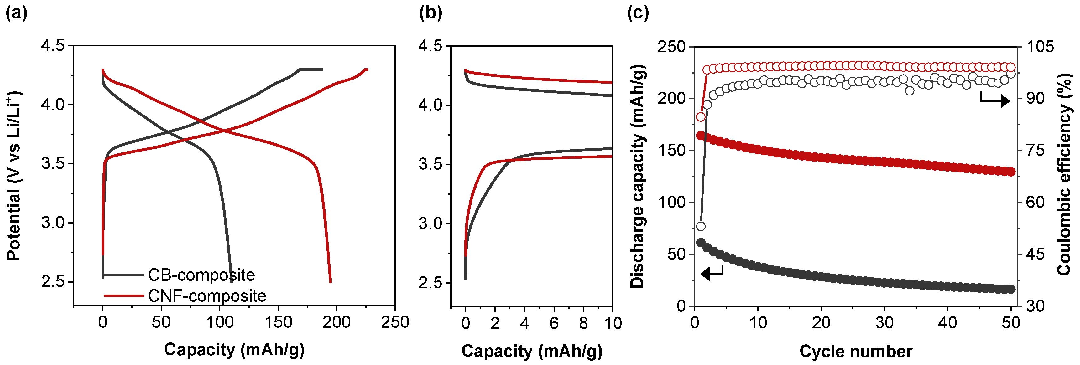
Figure 1. SEM images of the composite surface after pelletizing using (a,b) carbon black and (c,d) carbon nanofiber as conductive materials.
Batteries 09 00590 g001
Figure 2. (a) Charge–discharge curves and the (b) zoomed-in initial charging voltage profile at 0.05C. (c) Cycling performance with composite with carbon black and composite with CNF at 0.5C.
Batteries 09 00590 g002
Figure 3. Charge–discharge curves of (a) composite with carbon black and (b) composite with carbon nanofiber during cycling in the voltage range of 2.5–4.3 V at 30 °C. The curves come from the rate data in Figure 2c.
Batteries 09 00590 g003
Figure 4. Nyquist plots and the fitting plots of (a) composite of carbon black and (b) composite of carbon nanofiber after formation and 50th cycles at 30 °C. The inset depicts the equivalent circuit employed for fitting the Nyquist plot data. EIS tests are conducted at RT.
Batteries 09 00590 g004
Figure 5. (a) DC polarization (I–V analysis) at 30 °C and (b) calculated electronic conductivity of composites with carbon black and composite with carbon nanofiber.
Batteries 09 00590 g005
Figure 6. Illustration of ionic conductivity and electrical conductivity following fabrication of a composite using nano-sized carbon black and micron-sized carbon nanofibers as conductive materials.
Batteries 09 00590 g006
Table 1. Charge capacity, discharge capacity, and initial coulombic efficiency (ICE) of composite with carbon black and composite with carbon nanofiber at 0.05C at 30 °C. Charge and discharge capacity of cycle 1, cycle 50, and capacity retention after 50 cycles at 0.5C.
SampleCharge
Capacity
(mAh/g)
Discharge
Capacity
(mAh/g)
ICE
(%)
Discharge Capacity
@ 1st (mAh/g)
Discharge Capacity
@ 50th (mAh/g)
Capacity Retention
@ 50th (%)
CB-composite187.4110.258.861.416.727.1
CNF-composite225.9194.786.2164.5129.678.8
Table 2. Simulated results for the Nyquist plots of Rbulk, RGB, and RCT.
SampleRbulk
(Ω)
RGB
(Ω)
RCT
(Ω)
CB-compositeAfter formation36.559.1648.1
After 50th cycle71.8152.4800.5
CNF-compositeAfter formation37.219.8302.5
After 50th cycle41.935.0428.1
Disclaimer/Publisher’s Note: The statements, opinions and data contained in all publications are solely those of the individual author(s) and contributor(s) and not of MDPI and/or the editor(s). MDPI and/or the editor(s) disclaim responsibility for any injury to people or property resulting from any ideas, methods, instructions or products referred to in the content.

