1. Introduction
Lithium-ion batteries (LIBs) dominate the market of portable consumer electronic devices since SONY Corporation launched the first commercial product in the 1990s. As the most studied energy storage devices, LIBs have attracted more and more attention. Their high operation voltage, high energy density, small self-discharge, high-rate performance, and long cycle stability make them especially attractive to electric vehicles (EVs) [
1,
2,
3,
4,
5]. Nevertheless, transport electrification is one of the biggest challenges we face today [
2]. There are three significant issues to be addressed for the widespread application of LIBs in EVs: safety, long driving range, and low cost [
5,
6]. In terms of safety and short driving range, one of the most promising solutions is all-solid-state batteries. Regarding the cost, the high cost of LIBs has become a bottleneck for its widespread application, as the cost of energy-storage systems must reduce to
$125 kwh
−1 to meet the economical requirements [
7].
The cost of batteries mainly consists of two parts, i.e., raw materials and manufacturing costs. Reducing manufacturing energy consumption and increasing electrode thickness are two effective methods to lower the manufacturing cost of LIBs [
7]. The fabrication of electrodes with the conventional slurry-casting (CSC) method involves mixing the active material, polymer binder, and conductive additive in water or
N-methyl-pyrrolidone (NMP). After several hours of mixing, the slurry is cast on the current collector, dried, and calendered to form electrodes. NMP is the commonly used organic solvent in cathode fabrication, while water is used for anode. An oven dozens of meters long with a temperature higher than 120 °C is required in the process of drying for both anode and cathode. The energy consumed in slurry making and coating accounts for approximately 50% of all cell production processes in a 20.5 Ah, 3.7 V, and 1 ppm production line [
8]. Numerous research groups have explored the possibility of removing the solvent from the electrode fabrication process to reduce the manufacturing cost [
9,
10,
11]. A solvent-free (SF) electrode has been fabricated with the help of laser technology. The laser is focused on the electrode material to achieve pulsed-laser deposition. However, the process requires high vacuum and extremely high annealing temperature while only forming thin films of the electrode [
12,
13]. Radio-frequency magnetron sputtering method can be applied with a relatively low-temperature substrate of 350 °C. However, expensive equipment and inert atmosphere are required, which limits its large-scale application [
14]. Li
4Ti
5O
12 anodes were fabricated with the dry-spraying method, where the electrode component mixture was sprayed directly onto the current collector through the slot in N
2 atmosphere, and subsequently isothermally hot-pressed several times [
15]. Another common method for SF electrode fabrication is electrostatic spray deposition (ESD), for which high voltage was added between the deposition nozzle and the grounding current collector, and the deposition material is atomized. The charged particles are deposited onto the current collector and subsequently heat pressed, or heat rolled, to form electrodes [
16,
17,
18]. All these methods are either quite complicated or energy-consuming, not suitable for mass production.
Polytetrafluorethylene (PTFE) also has been demonstrated for SF electrode fabrication. Yang et al. fabricated SiO anode with PTFE and polyvinylidene fluoride (PVDF) using its sticky property, where PTFE, PVDF, SiO, and acetylene black were dry mixed and pressed to form the final electrodes [
19]. Another promising method for SF electrode fabrication is using fibrillizable polymer, in most cases polytetrafluorethylene (PTFE), to replace the conventional soluble binder, where high shear, hot-rolling, and hot lamination processes were involved. PTFE can be stretched to form fiber under high shear, which can act as a net to support active material and conductive additives. The mixture of the electrode component was hot-rolled after mixing under high shear to form a free-standing film and finally laminated with the current collector using hot-rolling again. Since Maxwell’s company first revealed the SF electrode production process for supercapacitors using PTFE as the binder in 2004, the method attracted more and more attention with the widespread utilization of EVs [
20]. However, the study mainly focused on electrodes applied in supercapacitors or cathodes in LIBs due to its instability when applied in anodes [
6,
21]. The energy level of the lowest unoccupied molecular orbitals (LUMO) of PTFE is relatively low, which implies that PTFE accepts electrons readily, making it electrochemically unstable in an anodic environment [
22,
23]. For LIBs, the electrons are favorably transferred to the LUMO of PTFE to generate lithium fluoride and carbyne through a defluorination process [
24,
25,
26]. The sub-micro scale carbyne is unstable and could be further decomposed to amorphous carbon, which cannot withstand the volume shrinkage and expansion in the process of discharge and charge, resulting in poor cycling stability [
27,
28,
29,
30].
Increasing the loading of active material is another important way to decrease manufacturing costs because fewer current collectors, separators, and other auxiliary materials are required per unit capacity. However, the electrode kinetics is unfavorable for a thick electrode, resulting in poor C-rates performance. Moreover, the thick electrode is not compatible with the slurry-casting process. Breakdown of electrode and delamination of active material from the current collector caused by an uneven distribution of binder in the drying process limit the practical implementation of thick electrode. However, it is facile for thick electrode fabrication using a solvent-free method, since it avoids the drying process.
Therefore, developing a rapid and facile solvent-free electrode fabrication method compatible with the current commercial LIBs production line is highly desired. PTFE has shown great potential for cathode production in LIBs and electrode fabrication in capacitors due to its compatibility with the current commercial production line [
20,
21]. Post-Li chemistries like Al or Zn are emerging as promising candidates for next-generation rechargeable batteries [
31,
32]. The application of the method also could be used for electrode fabrication for these batteries. In this study, we successfully extended PTFE for solvent-free anode fabrication. SF anodes with different active carbon materials, including graphite, hard carbon, and soft carbon, were fabricated with PTFE as binder. The SF graphite anode was unstable, while SF hard carbon and SF soft carbon anodes showed great long-term cycle life. Notably, the SF hard carbon electrode with a high loading of 10.7 mg/cm
2 showed similar long-term cycling stability and better C-rates performance compared to the CSC anodes, demonstrating its potential for large-scale production. To the best of our knowledge, it is the first time that the PTFE was utilized for solvent-free anode fabrication. It was proposed that the long cycle life performance of SF hard carbon and SF soft carbon anodes was attributed to the low volume variation during the charge/discharge process, and the electrodes were able to maintain their integrity even though PTFE was reduced to amorphous carbon.
2. Experimental Section
2.1. Primer Coated Current Collector Preparation
To increase the adhesion between electrode dry film and current collector, copper foil (10 μm) with primer was used as the current collector. The primer slurry was prepared by mixing polyacrylic acid (PAA), carbon black, and Carbon nanotube (CNT, Lanxi Zhide Advanced Materials Co., Ltd., Jinhua, China) in deionized water. The weight ratio of PAA/carbon black/CNT was 20/20/1. The prepared slurry was cast on copper foil with a doctor blade and subsequently dried in a blast air oven at 40 °C for 10 min. The thickness of the primer layer is approximately 1 μm.
2.2. Electrodes Fabrication
The commercial anode active material (graphite/soft carbon/hard carbon), carbon black, and PTFE powder (MTI, Shenzhen, China) were used directly for anode fabrication. A powder mixture was prepared by mixing the active material, carbon black, and PTFE powder in V-blender for 10 min. The weight ratio of active material/carbon black/PTFE was 90/5/5. Jet mill with 2 inches grinding chamber (Sturtevant, Hanover, MA, USA) was adapted to apply high shear with the grinding and feeding pressure of 80 and 60 psi, respectively, to fibrillate PTFE. The free-standing film formed with the dry mixture fed through the gap of calender rolls and then pressed under at temperature of 160 °C. The thickness of which was adjusted according to the gap of rolls of the calender machine with a speed of 10 cm/min. Finally, the free-standing film was laminated to the primer-coated current collector using hot rolling at 160 °C. For comparison, a CSC anode also was fabricated by mixing active materials with carbon black and aqueous carboxymethyl cellulose/styrene-butadiene rubber (CMC/SBR) binder (1:1, m:m) with the same weight ratio as the SF anode. The prepared slurry was cast onto the copper foil (10 μm, Blueglownano, Guangzhou, China) by doctor-blade-coating technology. After drying in a blast air oven for 30 min at 40 °C, the electrode was calendered to designated thickness. Both electrodes were cut into a disc of 15 mm diameter and further dried in a vacuum oven at 120 °C for 12 h before moving to half-cell assembly.
2.3. Hard Carbon Anode Prelithiation
The half pouch cell was assembled with SF hard carbon electrode as the anode and lithium foil as the cathode. Before prelithiation, the pouch half cell was aged for 12 h with a fixture to apply pressure. First, the cell was constant current discharged to 0.01 V, then set to rest for 30 min, and finally current charged to 1.5 V. The pouch cell was disassembled, and the SF anode was washed with diethyl carbonate (DEC) several times and then dried under room temperature in the glove box for further full cell assembly.
2.4. Cell Assembly and Electrochemical Characterization
Both SF and CSC half cells were assembled with 2032 coin cells (MTI, Shenzhen, China) in an argon-filled glove box, where water and oxygen concentrations were less than 0.01 ppm. Cellulose film (Celgard, Charlotte, NC, USA), lithium foil (Sigma Aldrich, 600 μm) and 70 μL 1.2 M LiPF6 in EC-EMC (30/70, v/v) with 2 wt.% vinylene, and 10 wt.% fluoroethylene carbonate (FEC) were used as separator, encounter electrode, and electrolyte, respectively. The full cells with NCM 523 electrode as cathode were assembled using the same method, except with prelithiated SF hard carbon electrodes.
For the half cell, the galvanostatic charge/discharge tests were performed over a voltage range of 0.01–1.5 V under room temperature using an 8-channel battery analyzer (Neware, Shenzhen, China). The C-rates conducted for rate performance testing ranged from 0.1 C to 2 C. All cells were aged under room temperature for 12 h before testing and underwent several formation cycles with the constant charge/discharge current of 0.05 C/0.05 C. The capacity retention was calculated based on the average delithiation capacity of the first three cycles in the subsequent cycles (excluding the formation cycles). For the full cell, the voltage range is 2.8 to 4.2 V. Autolab was used for electrochemical impedance spectroscopy (EIS) analysis with the frequency between 0.01 Hz to 1 MHz.
The pristine and cycled electrodes were observed using a scanning electron microscope (SEM). The cycled electrodes were charged to the full delithiation state after cell cycling, followed by disassembling the cell, dipping the electrode into DEC solution for 2 h to remove any residual electrolyte, and finally left for drying at room temperature overnight in an argon-filled glove box for further ex-situ analysis.
2.5. Adhesion and Mechanical Strength Characterization
Adhesion was tested using a tensile force machine (Dongri Instrument Co., Ltd., Dongguan, China,
Figure S1). Electrodes with 20 mm × 50 mm dimension were fixed between two parallel holders by double-sided tape (
Figure S1). The velocity is 50 mm/min. The same electrode stripes were used for mechanical testing.
3. Results and Discussion
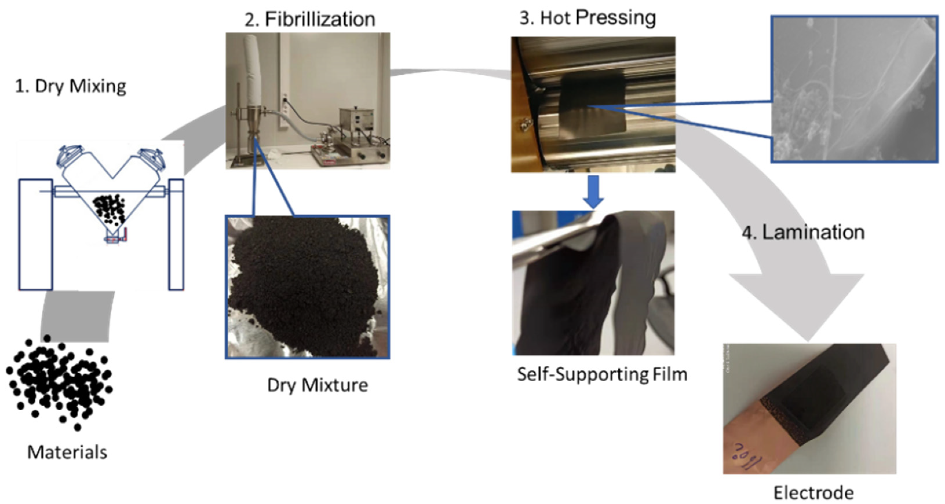
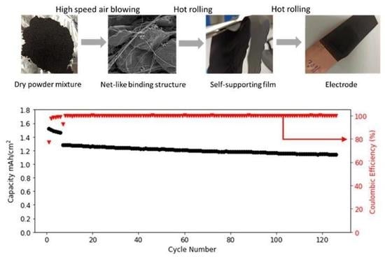
Graphite was first selected for the SF anode investigation due to its most widely used application in commercial LIBs. The schematic illustration of SF graphite anode fabrication is shown in
Figure 1. Graphite, PTFE, and carbon black were mixed for 10 min using a V-blender for the sake of uniform distribution of conductive additive. Then the mixed dry powder was fibrillated with a jet mill to form the dry mixture, and PTFE particles were stretched to fiber by high-shear force generated by high-pressure dry-compressed air. Therefore, PTFE fiber holds graphite and carbon black together like a net structure. To increase the flexibility of the dry electrode film and the adhesion between the film and the current collector, the hot-pressing process with calender machine was involved in both free-standing film formation and film- and current-collector lamination. The flexible nature of PTFE makes the free-standing film fairly soft, which can be bent and folded several times without any obvious electrode cracks or particles peeling off from the electrode film. The flexibility and mechanical strength of the dry electrode film indicates a high degree of fibrillation and good functionality of PTFE, making the method compatible with today’s commercial roll-to-roll manufacturing process.
The adhesion strength between active materials layer and the current collector is a big issue for SF electrodes [
33]. It is critical for the SF method since PTFE is insoluble, resulting in less contact area between the electrodes film and current collector. For better adhesion, a conductive adhesive primer-coated copper foil was used as current collector. The optimal temperature for the graphite film to current-collector lamination also was investigated. As shown in
Figure S2, the adhesion increased from 16 to 21 N/m as the lamination temperature increased from 100 to 160 °C. When the lamination temperature was further increased to 180 °C, the adhesion did not change a lot.
The SEM-EDS mapping of pristine SF graphite electrode demonstrates that fluorine is uniformly distributed on the surface of the electrode (
Figure S3), demonstrating even distribution of PTFE on the electrode.
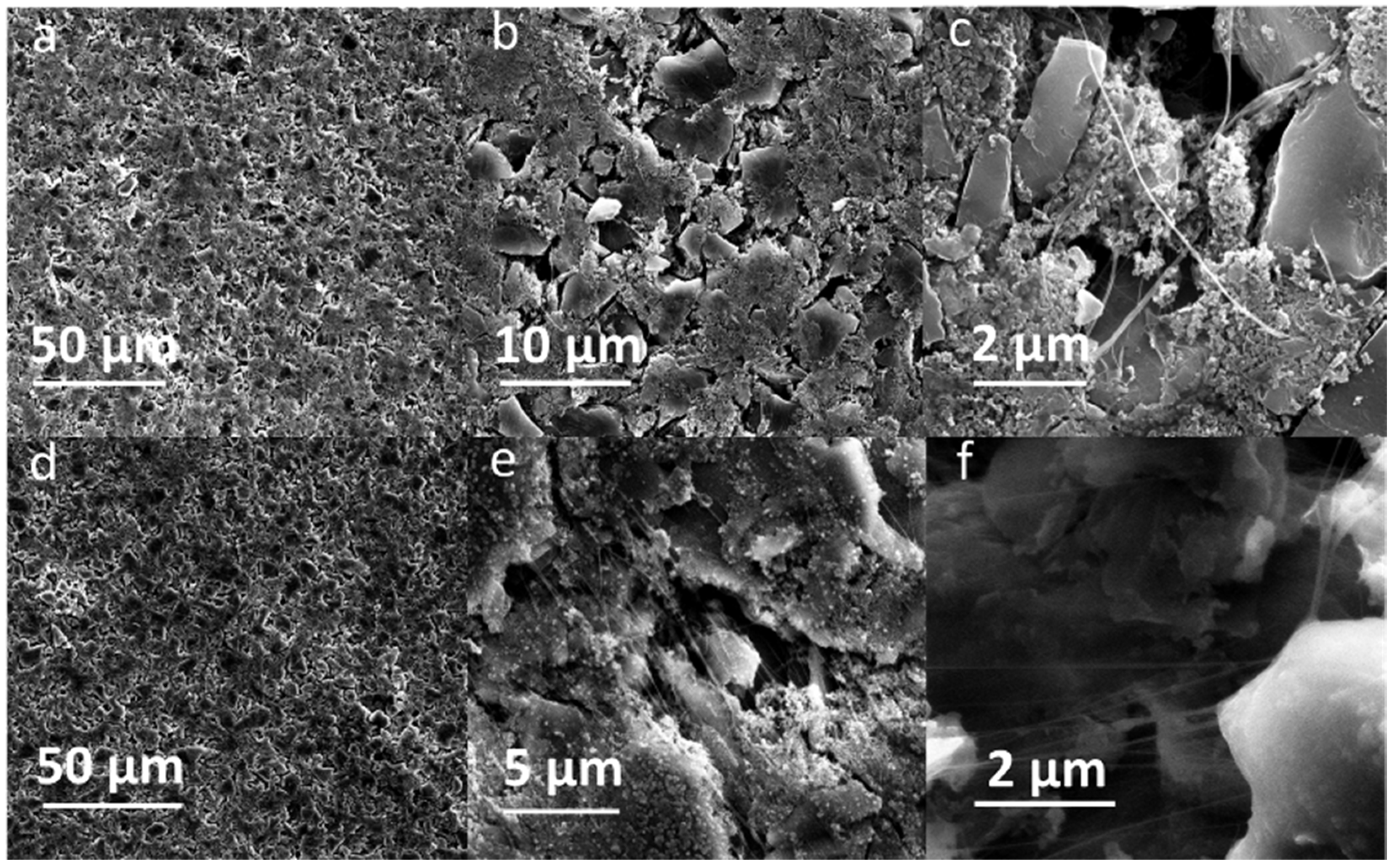
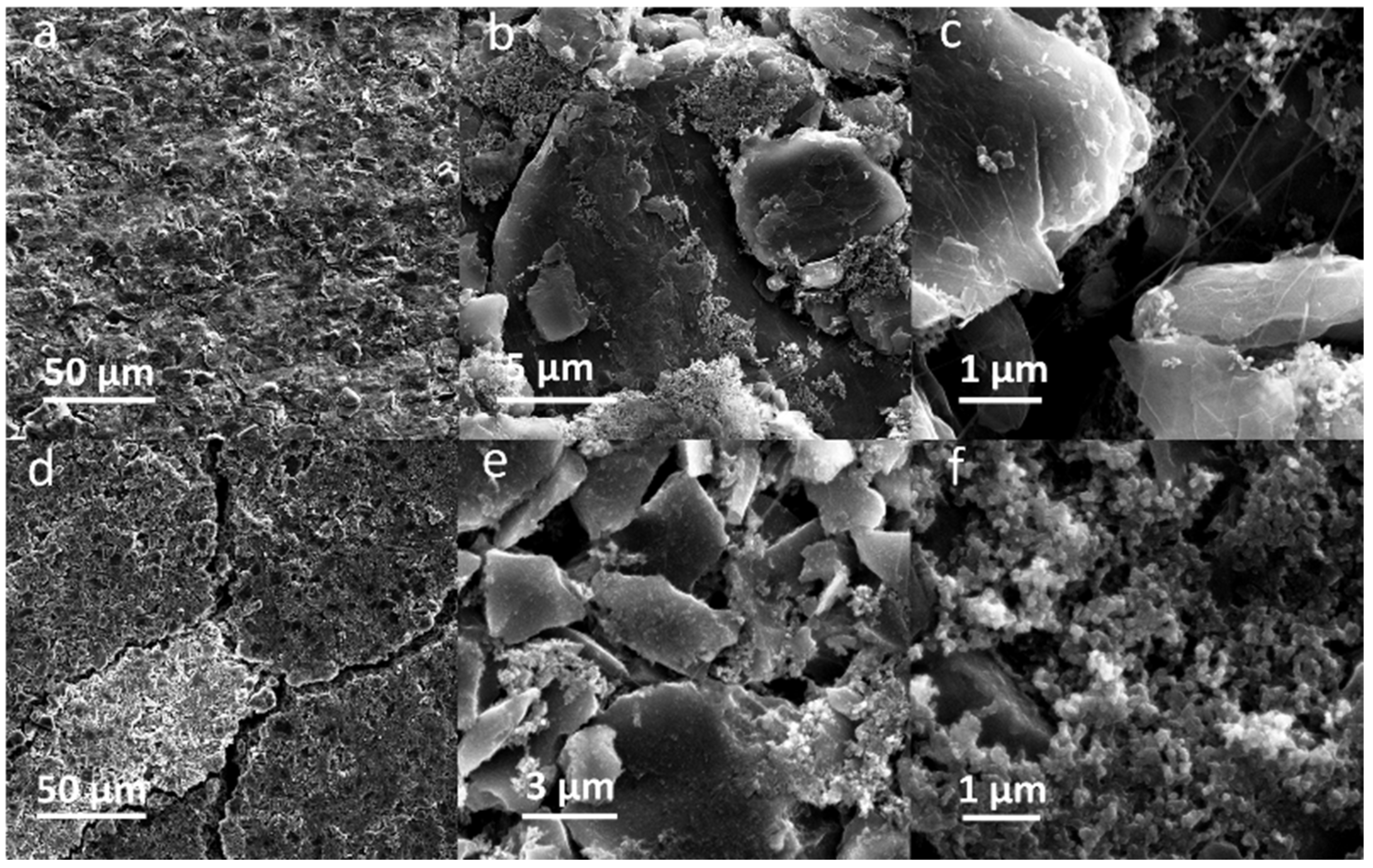
Figure 2a–c shows the SEM images of pristine SF graphite anode at different magnifications. The fiber of PTFE could be observed from the top view of SEM images (
Figure 2b,c) of the pristine graphite electrode, which bundles graphite to form a net-like structure, ensuring the free-standing film with good mechanical stability with a tensile strength of 8 N/m and good flexibility.
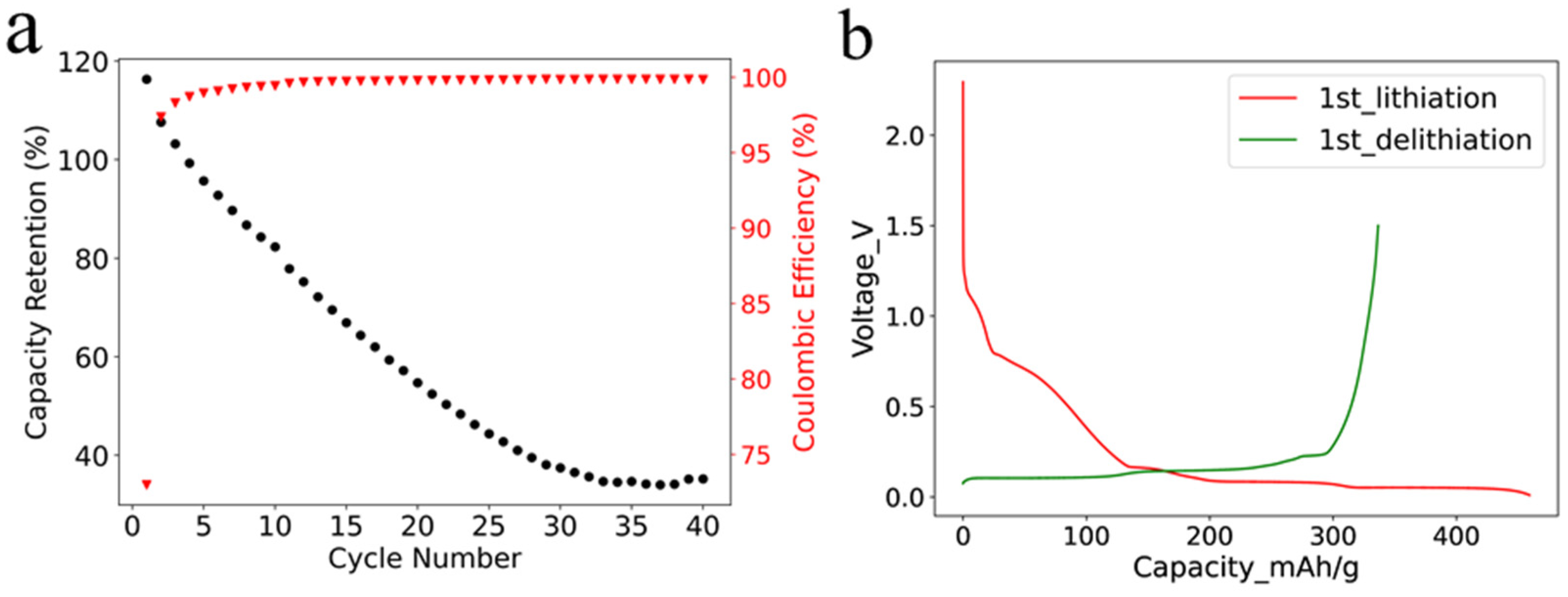
The cycling stability of SF graphite anode was studied in half cells with a current of 0.1 C at room temperature. It is worth mentioning that the areal loading of the SF graphite anode was 12.4 mg/cm
2, which was higher than the commercial one. As shown in
Figure 3a, the capacity faded fast even under a small current, with only approximately 30% capacity retention after 35 cycles. The fast capacity fading could be ascribed to the reaction of PTFE and lithium-ion in the first lithiation process. Most of the PTFE was reduced by lithium-ion, and the adhesion and cohesion degraded. The low initial coulombic efficiency (ICE) of 73% also was caused by the irreversible reaction (
Figure 3b) [
26], which was illustrated by Equation (1).
It is worth noting that earlier studies demonstrated relatively stable cycling performance of PTFE-based graphite anode using dry-press procedure. The difference of stability could be ascribed to electrode fabrication procedure, electrode structure, and testing condition [
34,
35,
36]. According to the studies mentioned above, the graphite electrodes were fabricated by mixing PTFE with graphite and then dry pressed onto substrate, while we used high-speed air to fibrillate PFTE. The fine PTFE fiber in our study has more chance to accept electrons and become reduced. High porosity could help to accommodate the volume variation of graphite electrodes during charge/discharge process [
34]. Current density is another factor affecting the stability of electrodes. PTFE-based graphite anodes are more stable under 0.1 mAh/cm
2 than those under 0.4 mAh/cm
2 [
35]. A further factor, which could degrade the stability of SF graphite electrodes in our research, is the high-active material loading and increased density of electrode (12.4 mg/cm
2, 1.68 g/cm
3). In summary, inferior stability of SF graphite electrodes in our system could ascribe to high loading of graphite, high-pressed density, and the easy reduction in fibrillated PTFE.
The irreversible capacity of the first cycle was 1260 mAh per gram of PTFE, resulting from the irreversible reaction of PTFE with lithium-ion and the solid electrolyte interphase (SEI) film formation in the first lithiation process. The reduction in PTFE was further confirmed by X-ray diffraction (XRD) characterization of pure PTFE powder, graphite powder, and SF graphite electrode after first lithiation. The characteristic peak of PTFE at 18.2° was not identified for the SF graphite anode, demonstrating the reduction in PTFE (
Figure S4). The results are consistent with those reported in the literature [
26]. The coulombic efficiency increased to more than 99% in the second cycle, indicating that most PTFE was reduced in the first cycle. The coulombic efficiency (CE) increased to 99.6% and 99.8% and remained stable after 10 cycles and 20 cycles, respectively. The high CE implied that most inserted active lithium could be reversibly extracted, which was crucial for the long cycle life of electrodes. The high CE further verified that the capacity fading was mainly caused by the loss of contact in active material rather than the irreversible side reactions.
The morphology of the cycled SF graphite electrodes was observed by SEM to explore the capacity fading mechanism. As shown in
Figure 2d, cracks could be observed from the top view of the cycled electrodes. There was no visible fiber left (
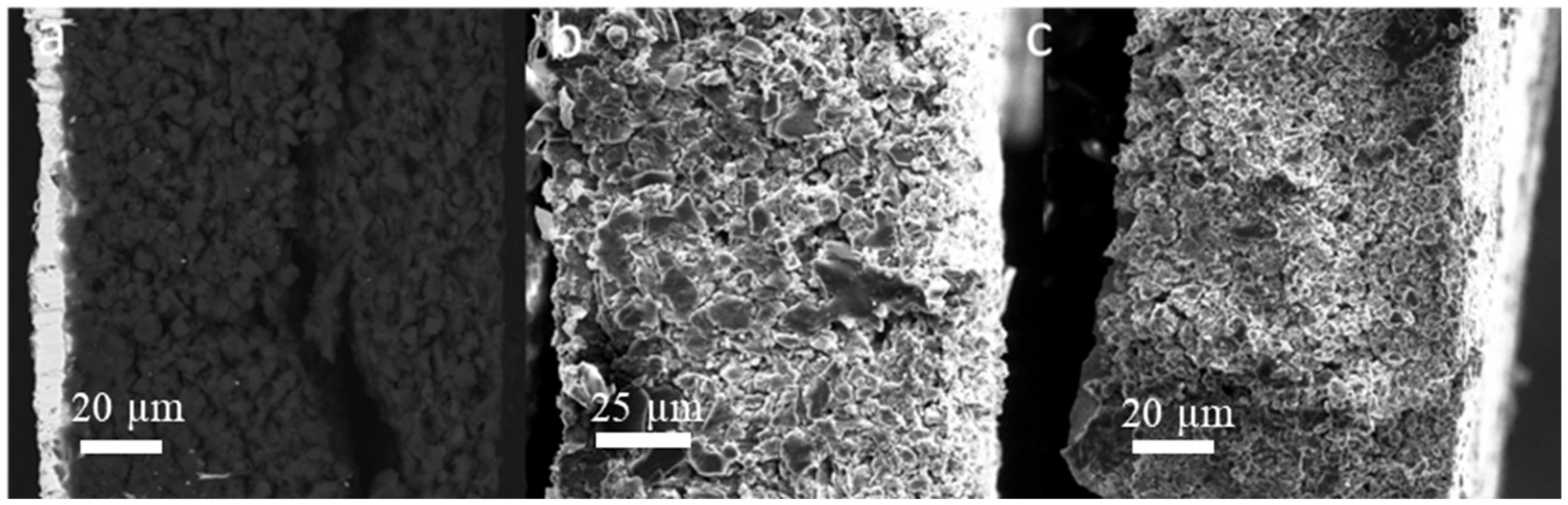
Figure 2e,f), indicating that most long PTFE fiber was reduced to short carbyne. The cross-sectional SEM images (
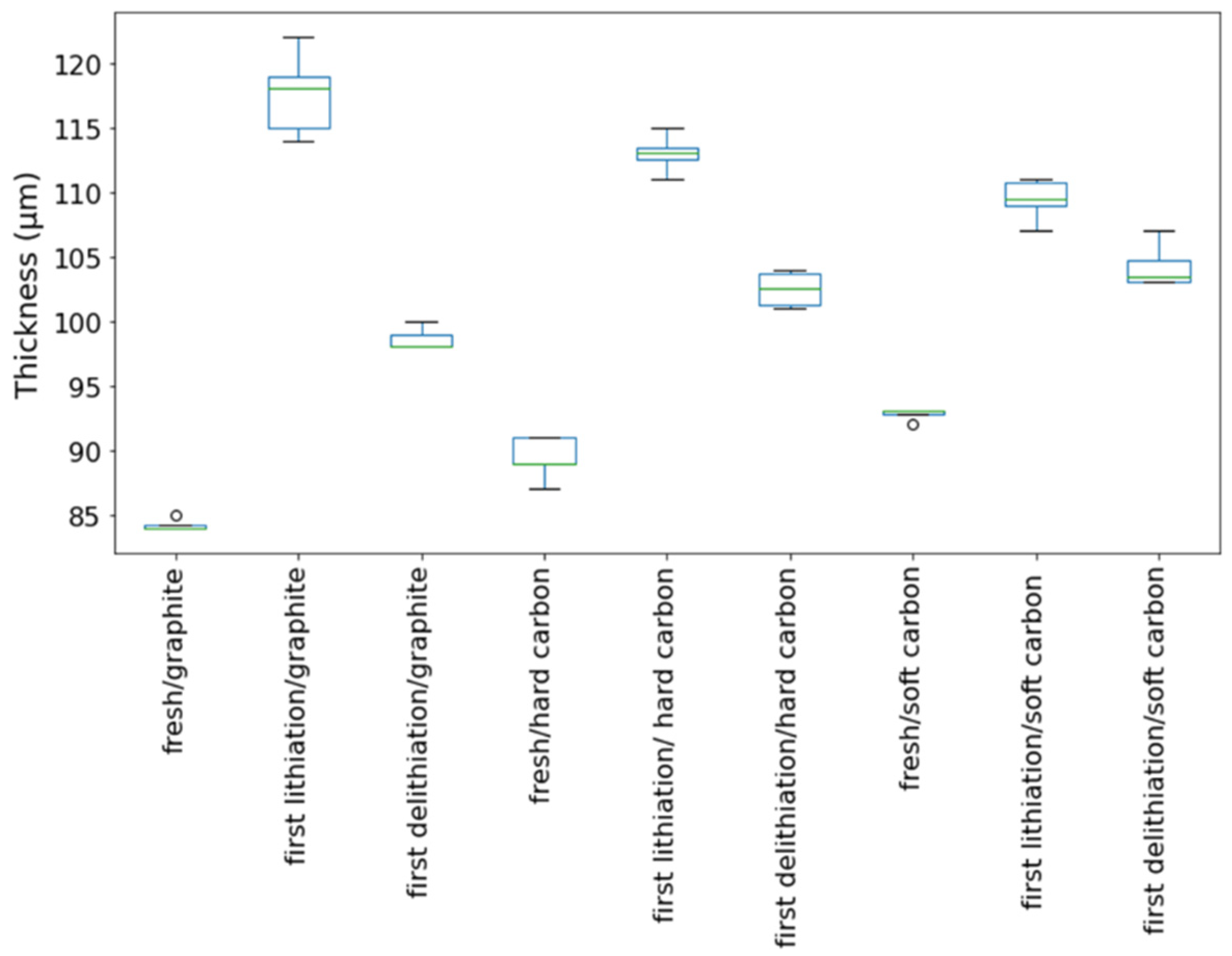
Figure 4a) showed that the electrode was uncompacted compared to the pristine one, losing contact of some active material to the electrode bulk parts or current collector. No obvious separation between electrode film and the current collector was observed, indicating good adhesion between the electrode film and the primer-coated current collector. Considering that the graphite has a big volume variation during the charge/discharge process, the thickness of the SF graphite anode at different states was measured. The thickness of SF graphite anode for the pristine, after the first lithiation process and after the first delithiation process, was 84.2, 117.6, and 98.6 µm, respectively (
Figure 5). The thickness of the first lithiated anode increased by 19.2% compared with the pristine one. Taking all these into consideration, the possible fading mechanism was that PTFE was reduced to carbyne with sub-micro dimension in the first lithiation process, which could be further decomposed to amorphous carbon [
24,
25,
27,
37]. The sub-micro scale carbyne and amorphous carbon cannot bind active materials together when the electrode has huge volume variation during cycling, losing the integrity and resulting in fast capacity fading [
28,
29,
30].
As one alternative to graphite, hard carbon has the advantage of better rate performance as well as smaller volume variation during charge/discharge cycling [
38,
39,
40,
41]. To confirm our hypothesis on SF graphite fading mechanism, the cycling stability of SF hard carbon anode fabricated with the same procedure as SF graphite was studied in half cells with a current of 0.3 C at room temperature. For comparison, CSC hard carbon anodes with CMC/SBR as binder also were fabricated. Considering that the electrode with high thickness is easily fabricated with our solvent-free method, the areal loading, and thickness and compacted density of the SF hard carbon anode are 10.7 mg/cm
2, 89.4 μm, and 1.20 g/cm
3, respectively. While for the CSC anodes, the areal loading, and thickness and density of the electrode are 5.6 mg/cm
2, 74 μm, and 0.76 g/cm
3, respectively. As shown in
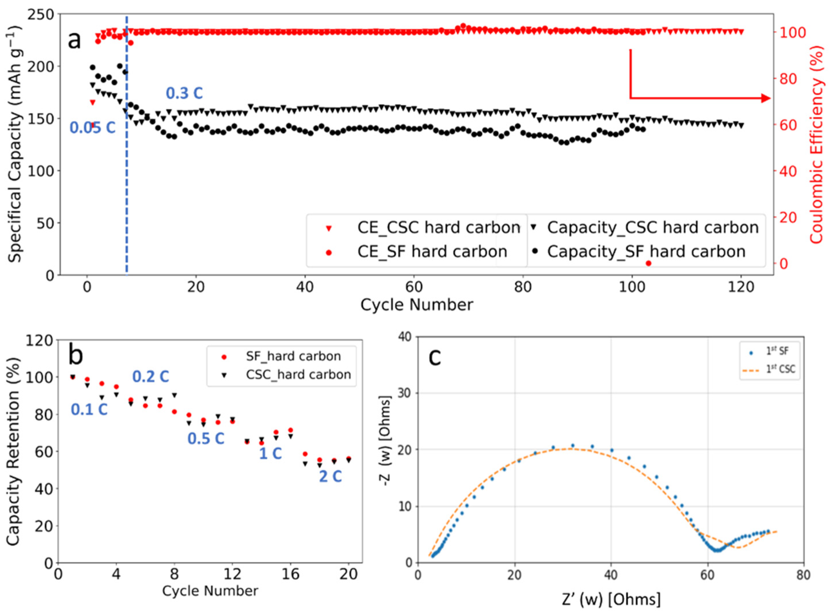
Figure 6a, the specific capacity for SF and CSC hard carbon anode was 172 and 175 mAh/g at 0.05 C. More than 80% capacity retention was obtained after 100 charge/discharge cycles for SF hard carbon anode. For the CSC anode, capacity retention was lower at approximately 76% under the same condition. The CE was more than 99.5% and remained stable after the first three formation cycles for SF and CSC anodes, demonstrating well reversible lithium insertion and extraction. It is worth noting that electrodes with high loading of 25 mg/cm
2 also could have been fabricated with high flexibility (
Figure S5).
C-rates performance comparison also was performed with charge/discharge current in the range of 0.1 C to 2 C (
Figure 6b). For the SF hard carbon anodes, the electrode delivered a specific capacity of 159 mAh/g at 0.1 C. The capacity retentions were 86%, 75%, 67%, and 54% at 0.2 C, 0.5 C, 1 C, and 2 C, respectively. While the capacity retentions for the CSC anode were 87%, 79%, 70%, and 55% at the same circumstance, which was comparable to the SF one. Considering that the SF anodes had higher loading and larger compacted density (1.20 g/cm
3 for the SF hard carbon anode compared to 0.76 cm
3 for the CSC hard carbon anode), it is fair to conclude that the SF anode has better C-rates performance. Both PTFE and CMC/SBR are insulating, which is unfavorable for the conductivity of the electrode. For the CSC anode, insulating CMC dissolved in water and formed a compact insulating layer around hard carbon particles to block the conduction pathway, resulting in increased resistance and low C-rates performance. While in the SF anode, high C-rates performance was achieved due to reduced blocking of active material, which could be further ascribed to the fibrous nature of PTFE binder. The EIS results of SF and CSC hard carbon electrodes after formation demonstrated that the two electrodes had similar resistance, which was consistent with the rate capability performance (
Figure 6b,c).
Both pristine and cycled SF hard carbon electrodes were characterized by SEM imaging. The pristine SF hard carbon electrodes showed similar morphology as the SF graphite electrode (
Figure 7a–c), as uniformly distributed PTFE fiber also could be observed for the hard carbon anode. However, the cycled SF hard carbon electrode presented quite different morphology characteristics (
Figure 7d–f). Unlike the cycled SF graphite anode (
Figure 2d), no apparent cracks were observed for the SF hard carbon electrode, and it maintained compact after 100 cycles (
Figure 7d), demonstrating its good integrity. The fibers on the surface of active material disappeared, while there were still many fibers left bridging the neighboring hard carbon particles. The different fiber morphology of cycled SF hard carbon and graphite anodes was attributed to their different volume expansion during the charge process. PTFE was only reduced to carbyne when electron transfer happens, which meant that degradation will not occur when the fibers do not contact the active materials directly. The fibers were broken down in SF graphite anode due to the significant volume expansion during the first lithiation process. The broken fibers fell on the surface of graphite and were further reduced to carbyne. However, in SF hard carbon anode, the low-volume variation during the charge/discharge process indicated that the fibers bridging the adjacent hard carbon particles can maintain their position and do not contact the active material directly; therefore, they had less possibility to be reduced to carbyne. This explains why only fibers bridging the adjacent hard carbon remained, while the fibers on the surface of the particles disappeared. The thickness of the pristine, first lithiated and first delithiated SF hard carbon electrodes is 89.4, 111.3, and 102.5 μm, respectively. Compared to the first delithated one, the thickness of the first lithiated SF hard carbon anode only increased 8.5%, which was much less than the SF graphite anode counterpart (
Figure 5). The cross-sectional SEM image also showed the compact structure of the cycled electrode (
Figure 4b). Voltage-capacity curves for SF and CSC hard carbon electrodes were shown in
Figure S5. The initial coulombic efficiency for SF and CSC hard carbon electrodes was 57% and 73%, respectively. The low ICE of SF electrodes was ascribed to the irreversible reaction between active lithium and PTFE in the first lithiation process. The reaction capacity of PTFE to active lithium here was 1021 mAh/g, which is in line with the theoretical value of 1070 mAh/g [
26]. A plateau around 0.85 V in the first lithiation process (
Figure S6a) also could be attributed to the reaction between PTFE and lithium ions. The plateau did not appear in the second cycle of SF electrode or first cycle of CSC electrode, which confirmed that the reaction is irreversible and was completed in the first lithiation process (
Figure S6c,d). The plateau at approximately 0.95 V of the CSC hard carbon electrode was ascribed to the formation of SEI film (
Figure S6b). To further confirm the stability of PTFE, electrodes with 85% PTFE and 15% carbon black were fabricated with the similar procedure, and half cells were assembled. Cyclic voltammogram (CV) was scanned at 0.001 mV/s (
Figure S7). In the first cycle, there was a reduction peak at around 0.9 V, which could be ascribed to the irreversible reaction of PTFE and lithium-ion. The CV results were consistent with the results of differential capacity (dQ/dV) and voltage-capacity curves in
Figure S6.
To further clarify the relationship between the cycle life of the anodes and the volume variation of the active materials, the SF soft carbon anode also was fabricated and investigated with the same procedure. As shown in
Figure S8, the SF soft carbon electrode showed comparative cycling performance to SF hard carbon anode, with roughly 80% capacity retention after 100 cycles under 0.3 C. The low ICE of 72% also is ascribed to the irreversible reaction between PTFE and active lithium in the first lithiation process, which is similar to the SF graphite and hard carbon electrodes. The thickness of SF soft carbon anode was measured to be 92.8, 108.5, and 104.2 μm for pristine first lithiation and first delithiation states, respectively. Similar SEM morphology was observed for both pristine and cycled electrodes (
Figure S9) compared to the SF hard carbon electrode. PTFE fiber was distributed evenly on the surface of soft carbon for the pristine electrode, and no apparent cracks were observed for the electrode after 100 cycles. The cross-sectional SEM images demonstrated the integrity of the electrode after 100 cycles (
Figure 4c). The cycling performance and morphology study of SF soft carbon electrode further supports our hypothesis that the stability of SF hard carbon and soft carbon electrode is attributed to its low-volume variation during the charge/discharge process.
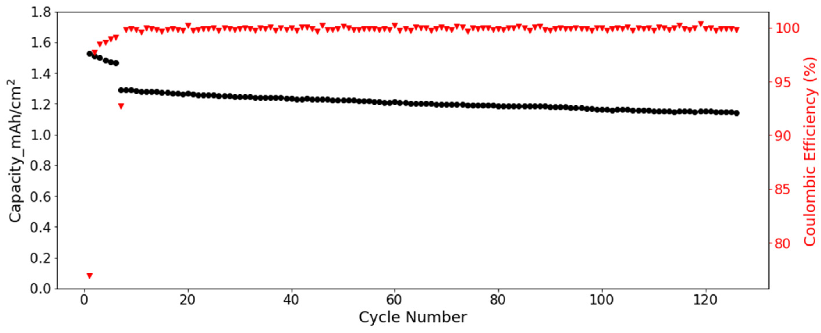
Full cells were assembled to further verify the cycling performance of SF hard carbon electrodes. Commercial NCM 523 electrodes were used as cathode. Considering the low ICE of SF hard carbon electrode, the SF hard carbon electrodes were prelithiated with an electrochemical method before cell assembly. The voltage-capacity curve for the lithiation process was shown in
Figure S10. For the cycling test, the cell went through five cycles of activation processes with a current of 0.05 C/0.05 C charge/discharge process. Then the cycling test was conducted under 1/3 C at room temperature. The SF hard carbon electrode demonstrated good stability with nearly 90% capacity retention after 120 cycles (
Figure 8). With prelithiation, the ICE increased from 57% to 77%. The CE increased to more than 99% and was very stable after activation.


 ,
, 