Article

The Electrochemical Characterization of Nanostructured Bi2Se3 Thin Films in an Aqueous Na Electrolyte

1
Institute of Chemical Physics, University of Latvia, LV-1586 Riga, Latvia
2
Faculty of Chemistry, University of Latvia, LV-1586 Riga, Latvia
*
Author to whom correspondence should be addressed.
Batteries 2022, 8(3), 25; https://doi.org/10.3390/batteries8030025
Submission received: 28 January 2022 / Revised: 4 March 2022 / Accepted: 16 March 2022 / Published: 18 March 2022
(This article belongs to the Special Issue Recent Advances in Aqueous Zinc-Ion Batteries)

Abstract

:
Due to their layered structure and high theoretical capacity, bismuth chalcogenides have been proposed as anodes in organic electrolyte Li- and Na-ion batteries. On the other hand, their electrochemical properties in aqueous systems have not been reported. Here, the electrochemical performance of Bi2Se3 thin films in 1 M NaNO3 aqueous electrolyte is presented. This aqueous Bi2Se3 system was found to have up to two orders of magnitude increased diffusion coefficients, compared to other anode materials in Na electrolyte-based systems, as well as limited anode electrode degradation over 5 CVs and significant changes in the anode after 30 CVs.

Graphical Abstract

1. Introduction

Effective storage of electrical energy is one of the greatest challenges in the world today [1]. With the growing usage of electrical vehicles, portable devices, and solar and wind energy power plants, which will require energy storage and redistribution units to manage short-run fluctuations in supply and demand, battery production is currently one of the major challenges. While lithium-ion batteries have shown the best performance on the production level and dominated the field of electrical energy storage since the 1990s [2], at the moment, they face issues such as geographically localized mining sites, as well as expensive and flammable electrolytes. Limited lithium resources and high demand may lead to limited availability and high costs of lithium-ion batteries in the future. To prevent this, research is currently underway in several directions.
One direction is to increase the energy and power density of battery electrode materials to reduce the number of individual cells needed, thus reducing the overall costs. It is possible to increase the energy and specific power of batteries by improving the anodes. Among the commercially used anodes, because of the reliable cycling performance, graphite has been the most popular one for 30 years. The main disadvantage of the graphite anode is its limited capacity and charging speed [3], and given the active development of chemical current sources and the expansion of their applications, the search for alternative anodes is an urgent task. Another direction that can significantly reduce the cost of batteries without losing their performance is the development of sodium-ion batteries. The abundance of Na (earth crust contains approx. 2.8% Na but contains only 20 ppm Li) and its affordability makes sodium-ion batteries a prospective alternative for the state-of-the-art LIBs that are used today. An additional advantage of sodium-ion batteries compared with lithium-ion batteries is, for example, the safety of their discharge to zero, which makes them easier to transport and store [4]. Therefore, research in the development of sodium-ion batteries is increasing exponentially every year.
Another crucial question in battery development is the choice of solvent for the electrolytes because solvents play key roles in ion transfer, as well as in determining the nature of discharge products and rechargeability. A suitable solvent should have a high dielectric constant and low viscosity; in addition, it should be inert to all cell components, be safe, non-toxic, and inexpensive [5]. Thus, aqueous electrolytes could be an attractive alternative for widely used organic solvents, as they are nonflammable, cheap, have a very high ionic conductivity, and therefore could operate at very high power [6]. Thereby, aqueous sodium-ion batteries (ASIBs) have attracted increased interest as next-generation batteries [7,8], especially for stationary energy storage plants [8], where the superior energy density of lithium-ion batteries is not significant, as they are not space-limited like electric vehicles and portable electronic devices.
The challenge with aqueous sodium-ion batteries is that most materials are not suitable as electrodes due to their insufficient electronic conductivity and electrochemical stability [9]. Overall, the materials that can be used as battery anodes can be divided into the following categories: materials based on intercalation, such as nanofibers and TiO2, metals based on alloying mechanisms such as Sb or Bi, and metal (such as Sb and Bi) chalcogenides based on the two-step reaction mechanism, including conversion and alloying reactions [10].
In combination with liquid organic electrolytes, bismuth chalcogenide anodes Bi2X3 (X = Te, Se, S) have shown high theoretical volumetric (up to 4500 mAh/cm3 for lithium-ion batteries) [11] and gravimetric capacities (~ 400–650 mAh/g for both lithium-ion and sodium-ion batteries) [12]. This was possible due to the unique structure of bismuth chalcogenides. For example, bismuth selenide in its crystal structure is a five-layer layer with a thickness of ~1 nm. Each layer of bismuth selenide consists of five-atomic covalently bonded Se1–Bi–Se2–Bi–Se1 planes, these layers are connected through a weak Van der Waals interaction. Due to the layered structure of bismuth selenide and the large interlayer distance (d (015) = 3.04 Å), cations can intercalate into Van der Waals gaps [11,13]. Among the bismuth chalcogenides, Bi2Se3 displays a high electrical conductivity (two orders of magnitude higher than Bi2S3 [14]), which allows for a better rate performance and has a high density, enabling a possibility to produce devices with high theoretical volumetric capacities up to 3667 mAh∙cm−3 [15], which is almost an order of magnitude higher than the commercial graphite for non-aqueous lithium-ion batteries (570 mAh∙cm−3) [16].
Bi2Se3 and its composites (e.g., with carbon allotropes) have shown promise as anode electrodes in non-aqueous electrolyte Na-ion battery cells [15]. However, to the best of our knowledge, an electrochemical investigation of Bi2Se3 as an anode electrode in aqueous electrolyte Na-ion cells has not been performed. In our study, an electrochemical investigation of physical vapor deposition (PVD) grown nanostructured Bi2Se3 thin films in aqueous electrolyte (1 M NaNO3) was performed for the first time.

2. Experimental

2.1. Synthesis and Characterization of Bi2Se3 Thin Films

Synthesis was carried out in a controllable vacuum furnace on microscope glass slides (75 × 25 mm), using a principal physical vapor deposition method, developed in the laboratory [17]. A programmable quartz tube furnace (GLX-1100X, MTI Corp) was used. For the synthesis, 15 mg raw Bi2Se3 (Sigma-Aldrich, Burlington, MA, USA, 99.999%) was used, which was weighted in ceramic boats using analytical scales (KERN “ABP 200-5DM”, ±0.01 mg). Quartz pipe (l = 60 cm, d = 4.5 cm) with adjustable valves on both sides was inserted inside the furnace. Raw Bi2Se3 (585 °C) and glass slides (330–380 °C) were placed at certain temperature regions inside this pipe. The quartz pipe was connected to the rotatory pump and nitrogen gas cylinder (Linde, Berlin, Germany, 99.999%). Before synthesis, the pipe was purged with nitrogen gas and vacuumed. After the vacuuming process, the quartz pipe was gradually heated up to 585 °C for 45 min and held at this temperature for 15 min at pressure 2–3 Torr. The physical vapor deposition process was stopped by reinjecting nitrogen gas into the pipe when it had cooled down to 470 °C.
The morphology and stoichiometry investigations of the synthesized Bi2Se3 thin films were performed using a Hitachi FE-SEM S-4800 scanning electron microscope (SEM), equipped with a Broker XFLASH 5010 energy-dispersive X-ray spectroscopy (EDX) sensor and an Asylum Research MFP-3D atomic force microscope. The samples with the appropriate structures were selected for electrochemical measurements.

2.2. Electrochemical Measurements

Electrochemical measurements were performed using a 3-electrode cell (Figure 1) and PalmSens4 potentiostat at room temperature. The setup was chosen to ensure an equal distance between the electrodes and the constancy of the working surface. The reference electrode (RE) was Ag/AgCl (3 M KCl), the counter electrode (CE) was Pt wire (ItalSens, PalmSens), and the working electrode (WE) was as-synthesized Bi2Se3 thin film (working area 0.19 cm2). As an electrolyte, 1 M NaNO3 (ThermoFisher, analytical grade 99%) was used. NaNO3 was used instead of sulfur-based electrolytes because of the surface activity of the anions in sulfides and sulfites, as well as the possibility for the sulfates to exist in the form of several crystalline hydrates (Bi2(SO4)3∙3H2O; Bi2(SO4)3∙3.5H2O; Bi2(SO4)3∙7H2O). On the other hand, the structure of bismuth nitrate crystalline hydrate is well studied and is Bi[(H2O)3(NO3)3]∙2H2O [18].
To ensure a stable electrical contact during the electrochemical measurements, the part of the working electrode that was not in a contact with the electrode was covered with silver conductive paint (Electrolube) to which a copper wire was attached. Cycling voltammetry (CV) curves were measured in the potential range (−1.0 V ÷ 1.3 V) at various scan rates (0.1 mVs−1 ÷ 1.0 mVs−1). The galvanostatic charge–discharge measurements were carried out with a current density of 90 mA/g.
EIS measurements were carried out in the frequency range 0.01–10,000 Hz, using open circuit potential. Spectra were acquired for a fresh sample and after the 1st, 5th, 10th, 20th, and 30th CV cycle. Spectra were analyzed using the Levenberg–Marquardt algorithm, the corresponding equivalent circuits were found, and the values of the respective circuit elements were determined.
After CV measurements, the working electrode (Bi2Se3 thin film) was washed with deionized water (4–5 times), dried at room temperature (25 °C), and investigated using SEM/EDX to analyze the structural and chemical changes in the electrode after the electrochemical measurements.

3. Results

3.1. Morphology of the Synthesized Structures

A synthesis method that promotes the growth of nanoplates with different angles against the substrate was selected to increase the surface area of the thin film Bi2Se3 electrode [17]. The thickness of the films was 500 nm, and the size of the nanoplates varied between 0.5 and 3 µm (Figure 2a). The EDX spectrum showed Si, Se, Bi, O, and C peaks. Si, O, and C peaks were background signals from the microscope and the substrate (Figure 2c). EDX quantitative analysis showed that synthesized samples were stochiometric, with an atomic ratio of 2:3 for Bi and Se, respectively (Table 1).

3.2. Electrochemical Measurements

Cyclic voltammetry curves in potential range (−1.0 V ÷ 1.3 V) at a scan rate of 0.25 mV s−1 showed two cathodic (I, II) and four anodic (III, IV, V, VI) peaks (Figure 3a). Peaks I and III represent reversible intercalation and deintercalation processes of Na+ ions (Equation (1)), which occur in the interlayer space of Bi2Se3 thin films [19]. Peaks II and IV, which overlapped with peaks I and III, represent substitution reactions between Bi2Se3 and a water-soluble Na2Se (Equation (2)) [15].
Bi2Se3 + xNa+ + xe ↔ Na+x[Bi2Se3]x−
Bi2Se3 + 6Na+ + 6e ↔ 3Na2Se + 2Bi
Anodic peak V represents the reduction of NO3 to NO2, but in the presence of dissolved oxygen in the electrolyte, NO2 oxidizes back to NO3 (Equation (3)) [20]. Peak VI (0.86 V), which appeared only during the first cycle, indicates the development of a solid electrolyte interphase (SEI) layer, which probably consisted of Na2O, Na2O2, and Na2CO3 (Equations (4)–(6)) [21] (Figure 3a).
NO3 + 2H+ + 2e ↔ NO2 + H2O
4Na+ + O2 + 4e → 2Na2O
2Na+ + O2 + 2e → Na2O2
4Na+ + 3CO2 + 4e → 2Na2CO3
Additionally, there was a tendency for the heights of peaks I and III, which correspond to the Na+ intercalation–deintercalation processes, to increase gradually in subsequent cycles (Figure 3a), which may indicate a surface treatment of Bi2Se3, involving the development of an SEI layer on the surface of the anode. The heights of peaks II and IV, which represent conversion reactions, slowly decreased (Equation (2)), which indicates possible changes in Bi2Se3 and Na2Se3 amounts in the cell. During the first two cycles (first and second cycle), a significant shift of the intercalation peak (I) toward the negative potential side was observed. The shifts can indicate possible cycling-induced structural changes in Bi2Se3 thin films. In the following cycles, the process stabilized and the intensities of subsequent peaks began to coincide, which may hint at the end of pretreatment of the electrode.
Na+ intercalation–deintercalation processes, which are represented by peaks I and III, were reversible but with different peak heights. That indicated two different mechanisms for these processes—intercalation is dominated by charge transfer, but deintercalation is dominated by thin-film mechanisms [22]. Further, intercalation is affected by the crystal lattice of the electrode, while deintercalation depends heavily on the interaction between the intercalated ions and is generally faster [22].
A comparison of Bi2Se3 thin film SEM images before and after five cycles of CV is shown in Figure 2a,b. It can be seen that, after the cycling, Bi2Se3 thin films were covered with an amorphous layer, which may indicate an SEI layer consisting of Na2O, Na2O2, and Na2CO3 [21,23,24]. These changes were also confirmed by the acquired CVs (Figure 3a). EDX analysis (Table 1) of the samples after cycling showed that only a small amount of Se dissolved (~10 percentage points), which indicates limited dissolubility of the Se in the electrode in 1 M NaNO3 in the first five cycles.
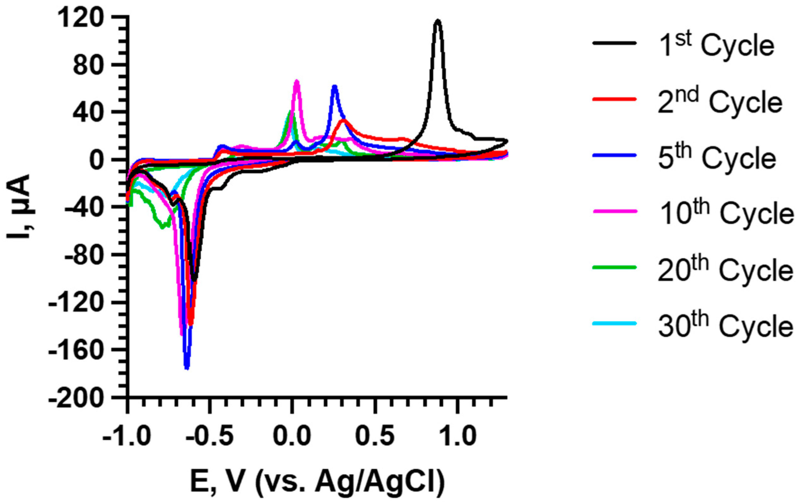
To investigate how the structure of nanostructured Bi2Se3 thin films changed during extended cycling, 30 CVs were obtained at the scan rate of 1.0 mVs−1 (Figure 4).
Continuous cycling showed that the intercalation peak (I) gradually shifted toward the negative potential from −0.59 V (1st cycle) to −0.65 V (10th cycle) and maintained the peak height above −100 µA up to 13th cycle, at which point the intercalation peak began to rapidly shift (approx. by −0.2 V per cycle) toward the negative potential, and the intercalation peak height diminished rapidly, becoming −58 µA at 20th cycle and −31 µA at 30th cycle. For the deintercalation peak (III), similar tendencies were observed—the peak voltage was stable around 0.26 V until the 7th cycle, after which it dropped to 0.03 V, around which it stayed until the 30th cycle. The deintercalation peak (III) current was above 40 µA until the 26th cycle and decreased down to 36 µA at the 30th cycle. The significant intercalation (I) and deintercalation (III) peak shifts that occurred during cycling toward negative potential indicate significant changes in the anode, such as irreversible reactions, structural degradation, and buildup of residue that may impede the charge–discharge processes, as observed in SEM images and EDX spectra after 30 cycles (Supplementary Figure S1, Table 1).
The galvanostatic charge–discharge profiles (90 mA/g) of the first five cycles (Figure 3b) showed a wide charge plateau at −0.41 V for the first cycle, which corresponds to the sodium intercalation, and shifted to the negative potentials during subsequent cycles. The discharge profiles showed the formation of the SEI layer at 0.5 V at the first cycle and the galvanostatic capacity of 90 mAh/g in the second and third cycles.
It should be noted that the performance of the anode is affected by the solvation of Na+ in a water–electrolyte solution. Solvated Na+ ions, when they approach the electrode surface, first need to be at least partially desolvated, and only then can enter the interplanar space. If the intercalated ion is partially hydrated, the coordinated water molecules shield the positive charge of the cations, thus mitigating the repulsion force of the Na+ ions. Thus, modification of the electrode material, to make it more hydrophilic, as well as pre-intercalation with water, may improve its performance [25].
EIS measurements were carried out both before the cycling and after a predetermined cycle number (1st, 5th, 10th, 20th, and 30th), which allowed the estimation of the electrochemical cycling-induced changes in Bi2Se3 thin films. Analysis of Nyquist plots (Figure 5a) revealed electrolyte resistance (Rel) at the Z’ axis cross-section at large frequencies. The semicircle at the medium-frequency range represents charge transfer resistance (Rct), and the linear part of the plot at the low-frequency range indicates the Warburg element, which represents the Na+ diffusion in Bi2Se3 interplanar space. After the first cycle, and also after the following cycles, an additional small semicircle can be observed in the low-frequency range, which represents the resistance RSEI of the SEI layer (Figure 5a). This assumption was supported by the CV data (Figure 4). The determined equivalent circuits (Figure 5b) showed constant phase elements both for Bi2Se3 thin films (CPEct) and SEI layer (CPESEI), indicating the increased roughness of the electrode (AFM measurements showed an increase in Ra from 73 nm to 116 nm for a 100 µm2 large section of the electrode) and the unevenness of the SEI layer (Supplementary Figures S1 and S2).
The quantitative values of Rel, Rct, RSEI, CPESEI, CPECT, and W were determined using the Levenberg–Marquardt algorithm. The acquired results (Table 2) show that Rs was stable (40 ± 2 Ω∙cm2) during the cycling, which indicates a stable electrolyte during 30 cycles. The formation of the SEI layer on the electrode surface after the first cycling significantly changed the behavior of the Bi2Se3 thin film. The formed SEI layer is an ionic conductor, which is characterized by a significant increase in the values of the Warburg element (from 16 to 756 Ω·s−1/2). In our study, the Warburg element revealed Na+ diffusion in Bi2Se3 interplanar space. During 30 cycles, the value of the Warburg element fluctuated within 750 ÷ 900 Ω s−1/2, which indicates a stable diffusion of sodium ions during the experiment. In addition to its contribution to diffusion, the formation of the SEI layer also led to kinetic changes, which were characterized by a decrease in Rct by a factor of 1.8 and an increase in CPEct by more than two orders of magnitude (from 4 to 553 Ω−1·s−n; Table 2). It is also worth noting that a gradual increase in Rct was observed during cycling, which indicates the appearance of additional kinetic limitations. A decrease in CPEct indicates irreversible changes on the surface of a thin film (Supplementary Figure S1). Additionally, during cycling, a decrease in the parameters RSEI (from 273 to 40 Ω∙cm−2) and CPESEI (from 365 to 71 Ω−1 s−n) was observed, which can be caused by the gradual dissolution of Na2O, Na2O2, and Na2CO3 from the surface of the Bi2Se3 thin film.
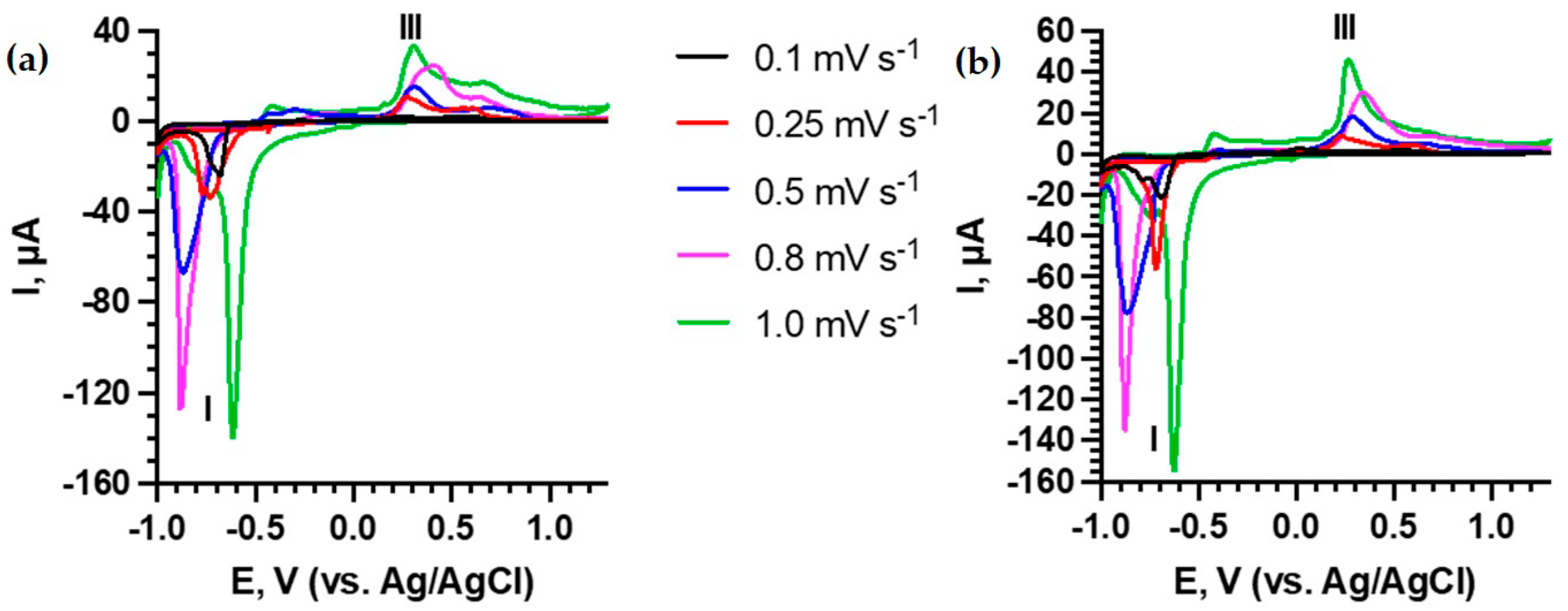
To determine the dominant process in intercalation and deintercalation (Figure 6), CVs at different scan rates from 0.1 to 1.0 mVs−1 were acquired for the second and third cycles, which show a stable electrode performance. The second and third cycles were chosen because, during the first cycle, SEI layer growth on the electrode surface occurred; thus, the second and third cycles revealed a situation in which electrode pretreatment was finished, and the electrode was still relatively unaffected by the electrochemical cycling, making the kinetic measurements representative of the Bi2Se3 anode material.
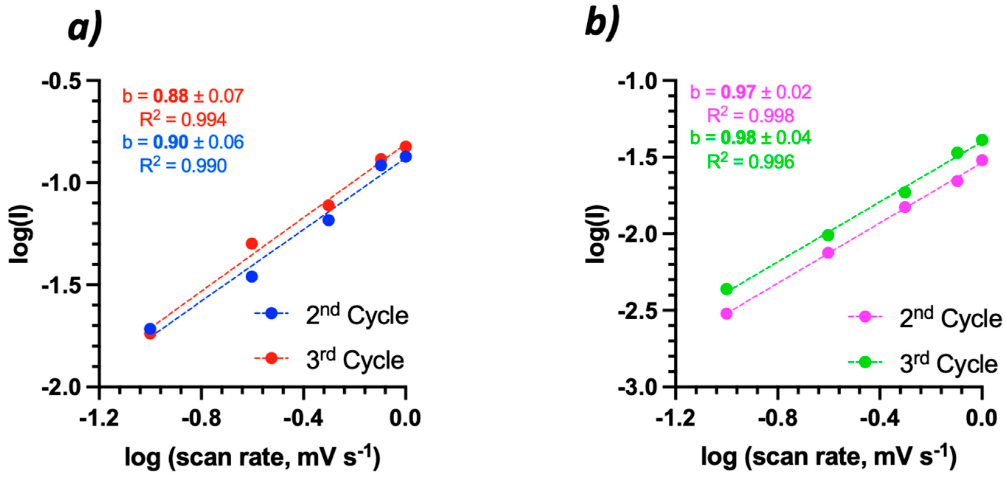
From Equation (7), and using peaks I and III (Figure 6), it was determined that, during the second and third cycle, the dominant process for Na+ intercalation and deintercalation was capacitive (b > 0.85) [26], and it included pseudo-capacitive, capacitive, and electrical double-layer capacitive processes (Figure 7).
I = a v b
where I—current for Na+ intercalation–deintercalation (mA); v—scan rate (mV s−1); a, b—fitting parameters for a linear graph.
A closer investigation on the capacitive contribution (Equation (8)) shows that at the scan rate 0.1 mV s−1, the process was diffusion-controlled (second cycle—58.5%; third cycle—61.0%). On the other hand (Figure 8), at faster cycling speeds (0.25—1.0 mV s−1), it is capacitive process dominated (>50%). The high capacitive contribution could indicate a rapid charge transfer process, as well as the diminishing of the Na+ diffusion barrier during the intercalation–deintercalation.
i ( V ) = k 1 v + k 2 v 1 / 2
where i(V)—Na+ current for Na+ intercalation–deintercalation (mA); k1v—contribution of the capacitive process; k2v1/2—contribution of the diffusive process.
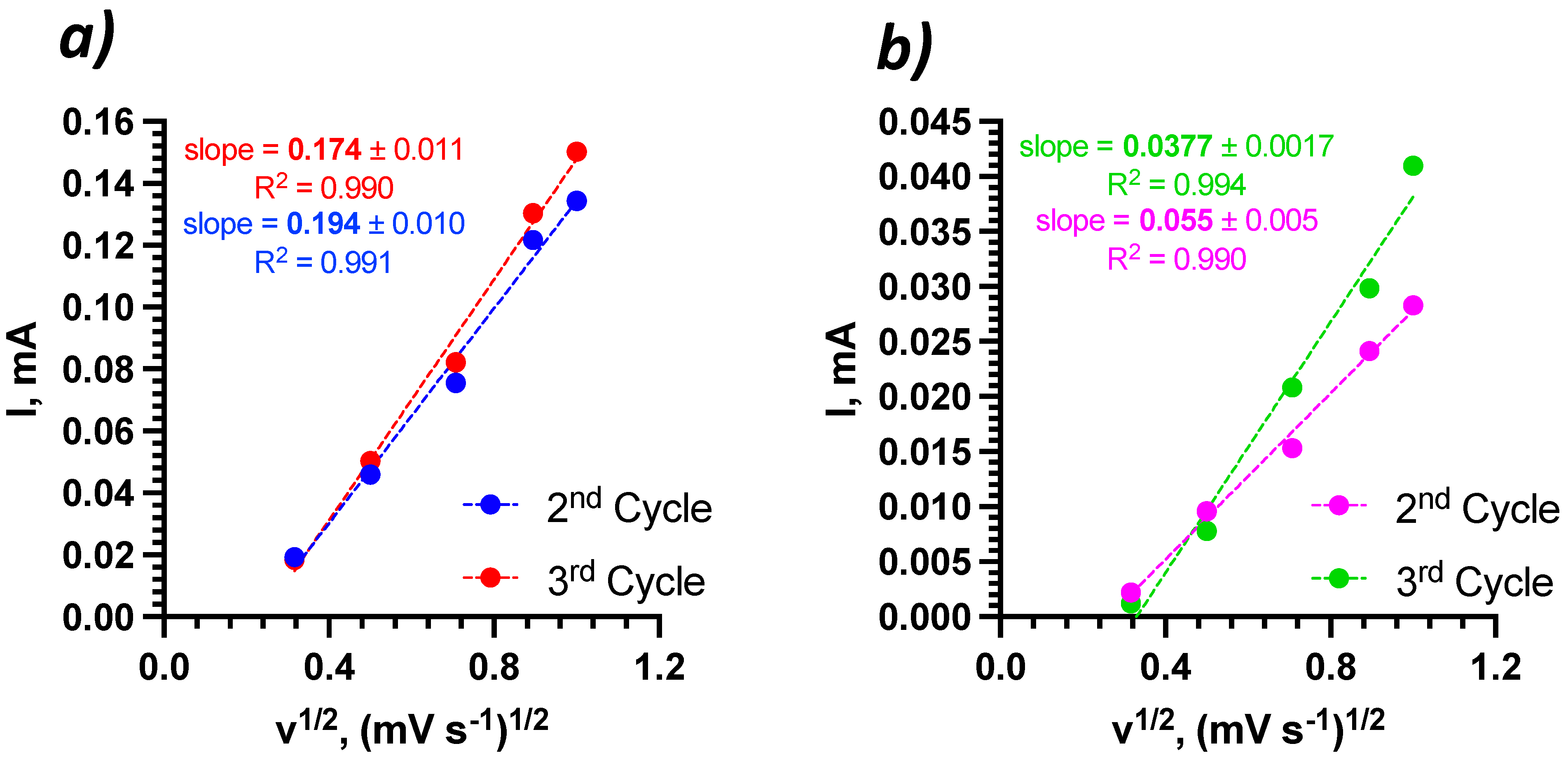
Na+ diffusion coefficients during intercalation–deintercalation were determined from the slopes of Figure 9, using Equation (9).
D = ( s l o p e 0.446 n F A C ) 2 ( R T n F ) ,
where D—diffusion coefficient (cm2 s1); slope—the slope of the graph; n—number of electrons that participate in a reaction; F—Faraday constant (C mol−1); A—surface area of the electrode (cm2); C—electrolyte concentration (mol cm−3); R—universal gas constant (J K−1 mol−1); T—temperature (K).
The calculated Na+ diffusion coefficient values (Table 3) show that the diffusion coefficients for intercalation were higher by ~1–2 orders of magnitude than those for deintercalation, indicating different reaction mechanisms, which were also confirmed by the acquired CVs (Figure 6). The comparison with diffusion coefficients for non-aqueous systems in which Bi2Se3 was used as an electrode shows that the diffusion coefficient for intercalation was two orders of magnitude higher than that in the aqueous system. The aqueous system’s diffusion coefficient for deintercalation was also 2–3 magnitudes higher than that for pure Bi2Se3 electrodes in the non-aqueous electrolyte and was comparable with Bi2Se3/CC heterostructure non-aqueous electrolyte, which is expected, as the added carbon cloth can provide a preferable architecture for ion diffusion [27]. It must also be noted that the effect of thickness should be considered when comparing different anode materials. Very large (higher than 200 µm) electrode thickness has a negative impact on the diffusion coefficient, as ions cannot penetrate the material and agglomerate on the surface of the electrode, thus saturating it and also enhancing the degradation risk [28]. As shown in Table 3, compared electrodes had thicknesses that were an order of magnitude lower than 200 µm; in these electrodes, the morphology of the electrodes affect the diffusion coefficient the most.

4. Conclusions

In this study, the electrochemical performance of nanostructured Bi2Se3 thin film as an anode in 1 M NaNO3 aqueous electrolyte was investigated. CV and EIS investigations showed that an unstable SEI layer formed in the first cycle at the potential 0.86 V. CVs at 1 mV∙s−1 and subsequent EIS measurements showed stable electrolyte performance (Rel) and a gradual increase in Rct, which indicates the emergence of additional kinetic limitations, while RSEI decreased significantly (>6 times). A long-term CV investigation consisting of 30 cycles with the scan rate of 1.0 mV∙s−1 showed a gradual degradation in the Bi2Se3 thin film, consistent with the EIS measurements. It was also determined that at lower scan rates (≤0.1 mV∙s−1), the intercalation–deintercalation was dominated by the capacitive process, while at higher scan rates (≥0.25 mV∙s−1), it became dominantly diffusion controlled. In comparison with Bi2Se3-based anode materials in aqueous Na electrolytes, our Bi2Se3 thin film-based system revealed up to two orders of magnitude increased diffusion coefficients.

Supplementary Materials

The following supporting information can be downloaded at: https://www.mdpi.com/article/10.3390/batteries8030025/s1, Figure S1: SEM images: (a) fresh sample; (b) after 30 CV cycles at 1 mV/s scan rate; Figure S2: AFM scans and Ra values for the roughness: (a) fresh sample; (b) after 30 CV cycles at 1 mV/s scan rate; Figure S3: XRD spectra of a fresh Bi2Se3 thin film on glass.

Author Contributions

Conceptualization, R.M. and Y.R. and V.L.; methodology, R.M., V.L., J.A.; investigation, A.S., V.V., V.L., R.M.; data curation, A.S., V.L., Y.R., R.M.; writing, R.M., V.L., Y.R.; supervision, A.V. and D.E.; project administration and funding acquisition R.M. and D.E. All authors have read and agreed to the published version of the manuscript.

Funding

This research and the APC were funded by the European Regional Development Fund (project number 1.1.1.2/VIAA/3/19/522, “Nanostructured binder-free Bi2Se3/CNT anode electrodes for sodium-ion batteries”).

Institutional Review Board Statement

Not applicable.

Informed Consent Statement

Not applicable.

Data Availability Statement

Data are available in the Supplementary Material.

Acknowledgments

This research was funded by the European Regional Development Fund (project no. 1.1.1.2/VIAA/3/19/522, “Nanostructured binder-free Bi2Se3/CNT anode electrodes for sodium-ion batteries”).

Conflicts of Interest

The authors declare no conflict of interest.

References

  1. Olabi, A.G.; Onumaegbu, C.; Wilberforce, T.; Ramadan, M.; Abdelkareem, M.A.; Alami, A.H.A. Critical review of energy storage systems. Energy 2021, 214, 118987. [Google Scholar] [CrossRef]
  2. Manthiram, A. Materials Challenges and Opportunities of Lithium Ion Batteries. J. Phys. Chem. Lett. 2011, 2, 176–184. [Google Scholar] [CrossRef]
  3. Cai, W.; Yao, Y.-X.; Zhu, G.-L.; Yan, C.; Jiang, L.-L.; He, C.; Huang, J.-Q.; Zhang, Q. A review on energy chemistry of fast-charging anodes. Chem. Soc. Rev. 2020, 49, 3806–3833. [Google Scholar] [CrossRef] [PubMed]
  4. Sawicki, M.; Shaw, L.L. Advances and challenges of sodium ion batteries as post lithium ion batteries. RSC Adv. 2015, 5, 53129–53154. [Google Scholar] [CrossRef]
  5. Roth, E.P.; Orendorff, C.J. How electrolytes influence battery safety. Electrochem. Soc. Interface 2012, 21, 45–49. [Google Scholar] [CrossRef]
  6. Cresce, A.; Xu, K. Aqueous lithium-ion batteries. Carbon Energy 2021, 3, 721–751. [Google Scholar] [CrossRef]
  7. Liu, Z.; Huang, Y.; Huang, Y.; Yang, Q.; Li, X.; Huang, Z.; Zhi, C. Voltage issue of aqueous rechargeable metal-ion batteries. Chem. Soc. Rev. 2020, 49, 180–232. [Google Scholar] [CrossRef] [PubMed]
  8. Kim, H.; Hong, J.; Park, K.Y.; Kim, H.; Kim, S.W.; Kang, K. Aqueous Rechargeable Li and Na Ion Batteries. Chem. Rev. 2014, 114, 11788–11827. [Google Scholar] [CrossRef] [PubMed]
  9. Yin, X.; Sarkar, S.; Shi, S.; Huang, Q.; Zhao, H.; Yan, L.; Zhao, Y.; Zhang, J. Recent Progress in Advanced Organic Electrode Materials for Sodium-Ion Batteries: Synthesis, Mechanisms, Challenges and Perspectives. Adv. Funct. Mater. 2020, 30, 1908445. [Google Scholar] [CrossRef]
  10. Zhang, W.; Zhang, F.; Ming, F.; Alshareef, H.N. Sodium-ion battery anodes: Status and future trends. Energy Chem. 2019, 1, 100012. [Google Scholar] [CrossRef]
  11. Ni, J.; Bi, X.; Jiang, Y.; Li, L.; Lu, J. Bismuth chalcogenide compounds Bi2×3 (X=O, S, Se): Applications in electrochemical energy storage. Nano Energy 2017, 34, 356–366. [Google Scholar] [CrossRef] [Green Version]
  12. Sun, J.; Li, M.; Oh, J.A.S.; Zeng, K.; Lu, L. Recent advances of bismuth based anode materials for sodium-ion batteries. Mater. Technol. 2018, 33, 563–573. [Google Scholar] [CrossRef]
  13. Hu, Z.; Liu, Q.; Chou, S.-L.; Dou, S.-X. Advances and Challenges in Metal Sulfides/Selenides for Next-Generation Rechargeable Sodium-Ion Batteries. Adv. Mater. 2017, 29, 1700606. [Google Scholar] [CrossRef]
  14. Liu, W.; Lukas, K.C.; McEnaney, K.; Lee, S.; Zhang, Q.; Opeil, C.P.; Chen, G.; Ren, Z. Studies on the Bi2Te3–Bi2Se3–Bi2S3 system for mid-temperature thermoelectric energy conversion. Energy Environ. Sci. 2013, 6, 552–560. [Google Scholar] [CrossRef]
  15. Xie, L.; Yang, Z.; Sun, J.; Zhou, H.; Chi, X.; Chen, H.; Li, A.X.; Yao, Y.; Chen, S. Bi2Se3/C Nanocomposite as a New Sodium-Ion Battery Anode Material. Nano-Micro Lett. 2018, 10, 50. [Google Scholar] [CrossRef] [PubMed] [Green Version]
  16. Chae, S.; Choi, S.H.; Kim, N.; Sung, J.; Cho, J. Integration of Graphite and Silicon Anodes for the Commercialization of High-Energy Lithium-Ion Batteries. Angew. Chem. Int. Ed. 2020, 59, 110–135. [Google Scholar] [CrossRef] [Green Version]
  17. Andzane, J.; Buks, K.; Strakova, M.N.; Zubkins, M.; Bechelany, M.; Marnauza, M.; Baitimirova, M.; Erts, D. Structure and Doping Determined Thermoelectric Properties of Bi2Se3 Thin Films Deposited by Vapour-Solid Technique. IEEE Trans. Nanotechnol. 2019, 18, 948–954. [Google Scholar] [CrossRef]
  18. Lazarini, F. Redetermination of the structure of bismuth(III) nitrate pentahydrate, Bi(NO3)3·5H2O. Acta Crystallogr. Sect. C Cryst. Struct. Commun. 1985, 41, 1144–1145. [Google Scholar] [CrossRef]
  19. Xu, B.; Qi, S.; He, P.; Ma, J. Antimony- and Bismuth-Based Chalcogenides for Sodium-Ion Batteries. Chem. An Asian J. 2019, 14, 2925–2937. [Google Scholar] [CrossRef]
  20. Xin, X.; Ito, K.; Dutta, A.; Kubo, Y. Dendrite-Free Epitaxial Growth of Lithium Metal during Charging in Li–O 2 Batteries. Angew. Chem. 2018, 130, 13390–13394. [Google Scholar] [CrossRef]
  21. Lee, M.H.; Kim, S.J.; Chang, D.; Kim, J.; Moon, S.; Oh, K.; Park, K.Y.; Seong, W.M.; Park, H.; Kwon, G.; et al. Toward a low-cost high-voltage sodium aqueous rechargeable battery. Mater. Today 2019, 29, 26–36. [Google Scholar] [CrossRef]
  22. Noel, M.; Rajendran, V. A comprehensive model for cyclic voltammetric study of intercalation/de-intercalation process incorporating charge transfer, ion transport and thin layer phenomena. J. Power Sources 2000, 88, 243–249. [Google Scholar] [CrossRef]
  23. Kim, S.; Jung, Y.; Park, J.; Hong, M.; Byon, H.R. Sodium fluoride-rich solid electrolyte interphase for sodium–metal and sodium–oxygen batteries. Bull. Korean Chem. Soc. 2021, 42, 1519–1523. [Google Scholar] [CrossRef]
  24. Jin, T.; Ji, X.; Wang, P.F.; Zhu, K.; Zhang, J.; Cao, L.; Chen, L.; Cui, C.; Deng, T.; Liu, S.; et al. High-Energy Aqueous Sodium-Ion Batteries. Angew. Chem. Int. Ed. 2021, 60, 11943–11948. [Google Scholar] [CrossRef] [PubMed]
  25. Xiao, B. Intercalated water in aqueous batteries. Carbon Energy 2020, 2, 251–264. [Google Scholar] [CrossRef]
  26. Mathis, T.S.; Kurra, N.; Wang, X.; Pinto, D.; Simon, P.; Gogotsi, Y. Energy Storage Data Reporting in Perspective—Guidelines for Interpreting the Performance of Electrochemical Energy Storage Systems. Adv. Energy Mater. 2019, 9, 1902007. [Google Scholar] [CrossRef]
  27. Dai, S.; Wang, L.; Shen, Y.; Wang, M. Bismuth selenide nanocrystalline array electrodes for high-performance sodium-ion batteries. Appl. Mater. Today 2020, 18, 100455. [Google Scholar] [CrossRef]
  28. Gao, H.; Wu, Q.; Hu, Y.; Zheng, J.P.; Amine, K.; Chen, Z. Revealing the Rate-Limiting Li-Ion Diffusion Pathway in Ultrathick Electrodes for Li-Ion Batteries. J. Phys. Chem. Lett. 2018, 9, 5100–5104. [Google Scholar] [CrossRef] [PubMed]
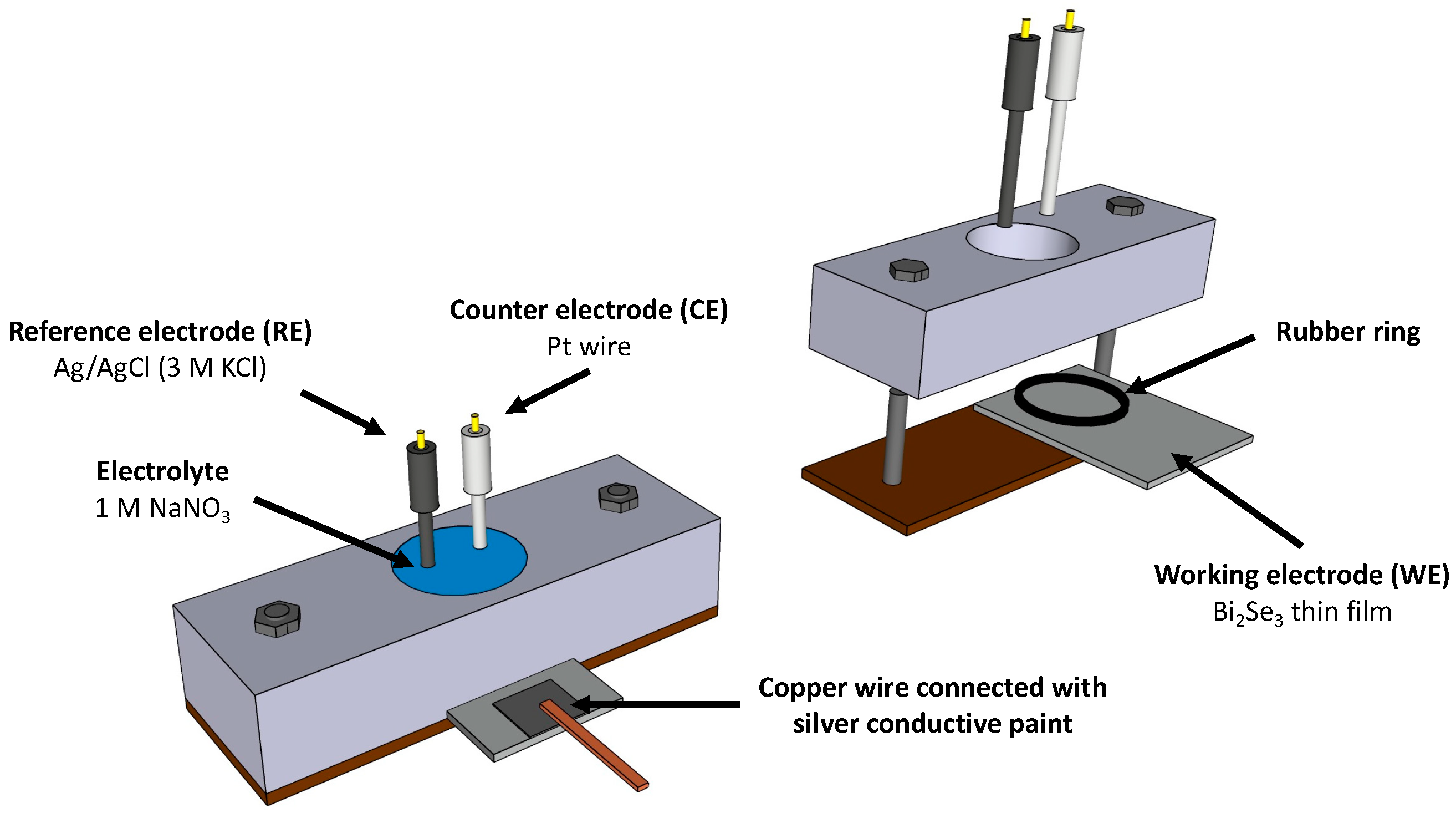
Figure 1. Schematics of the laboratory-made 3-electrode electrochemical cell.
Batteries 08 00025 g001
Figure 2. (a) SEM image of a fresh Bi2Se3 thin film; (b) SEM image of a fresh Bi2Se3 thin film after 5 CV cycles at scan rate 1.0 mVs−1; (c) EDX spectra of a fresh sample.
Batteries 08 00025 g002
Figure 3. (a) Bi2Se3 thin films CVs at scan rate 0.25 mVs−1 and (b) charge–discharge curves at 90 mA/g in −1.0 ÷ 1.3 V vs. Ag/AgCl potential range.
Batteries 08 00025 g003
Figure 4. Bi2Se3 thin films CVs in −1.0 ÷ 1.3 V vs. Ag/AgCl potential range at scan rate 1.0 mVs−1, 30 cycles.
Batteries 08 00025 g004
Figure 5. (a) Nyquist plots after predetermined CV cycle number; (b) determined equivalent circuits of the system.
Batteries 08 00025 g005
Figure 6. CVs for Bi2Se3 thin films with various scan rates (0.1—1.0 mV s−1): (a) 2nd cycle; (b) 3rd cycle.
Batteries 08 00025 g006
Figure 7. Log-scale plots of Bi2Se3 thin films in 1 M NaNO3: (a) Na+ intercalation; (b) Na+ deintercalation.
Batteries 08 00025 g007
Figure 8. The contribution of capacitive and diffusion-controlled processes of Bi2Se3 thin-film in 1 M NaNO3: (a) 2nd cycle; (b) 3rd cycle.
Batteries 08 00025 g008
Figure 9. The dependence of v1/2 vs. I of Bi2Se3 thin film in 1 M NaNO3 in the 2nd and 3rd cycles with fitted slope values for (a) Na+ intercalation and (b) Na+ deintercalation.
Batteries 08 00025 g009
Table 1. Quantitative EDX analysis before cycling and after 5 CV cycles at 0.25 mV∙s−1 and after 30 CV cycles at 1 mV∙s−1. σ—standard deviation.
Before CyclingAfter 5 CyclesAfter 30 Cycles
Elementmass %atomic %3σ, mass %mass %atomic %3σ, mass %mass %atomic %3σ, mass %
Bismuth58.5327.035.2945.7110.193.4429.514.312.24
Selenium33.6141.082.9915.919.391.7411.274.361.26
Oxygen0.724.370.5810.2329.812.5720.6639.445.29
Nitrogen0.704.840.671.735.760.615.8412.741.89
Carbon0.393.090.390.090.370.120.000.000.00
Silicon2.739.370.4110.0016.600.962.512.730.31
Sodium0.632.650.219.0218.291.2722.4229.783.00
Magnesium0.793.140.211.001.910.190.550.690.16
Potassium0.010.020.082.252.680.233.102.420.30
Calcium1.824.380.252.202.560.220.360.280.12
Chlorine0.000.000.001.852.430.213.783.260.36
Table 2. Impedance spectra equivalent circuit element values after different CV cycles.
Fresh SampleAfter the 1st CycleAfter the 5th CycleAfter the 10th CycleAfter the 20th CycleAfter the 30th Cycle
Rel, Ω∙cm2364141394341
RSEI, Ω∙cm2-273157965840
CPESEI, Ω−1 s−n-36537911112671
Rct, Ω∙cm215969001010115511781221
CPEct, Ω−1 s−n45533982729557
W, Ω·s−1/216756809785759896
Table 3. Na+ intercalation–deintercalation diffusion coefficient (cm2 s−1) comparison with other anodes–electrolytes.
ElectrodeThicknessElectrolyteIntercalationDeintercalationCycleReference
Bi2Se3 thin film500 nm1 M NaNO31.1 × 10−11
1.4 × 10⁻¹¹
5.1 × 10⁻¹³
1.1 × 10⁻¹²
2nd
3rd
This work
Bi2Se3/CC a1–20 µm * 1 M NaClO4 EC/PC (1:1) 2.2 × 10⁻¹³—9.7 × 10⁻¹² 1st[27]
Bi2Se3 microspheres1–20 µm *1 M NaClO4 EC/PC (1:1) 9.3 × 10−135.7 × 10−151st[27]
a Bi2Se3 nanocrystalline array grown on flexible conductive carbon cloth. * Authors did not provide the thickness of the electrode; therefore, values estimated from the loading factor and the density of the materials in the electrode.
Publisher’s Note: MDPI stays neutral with regard to jurisdictional claims in published maps and institutional affiliations.