1. Introduction
Li-ion battery cells have been widely adopted for reasons such as less self-discharge, less memory effect, higher energy density per weight and volume, stable performance, and longer cycle life compared to other types of secondary batteries. They are used in a variety of systems such as portable electronics [
1], electric vehicles [
2], spacecraft and aircraft power systems [
3], renewable energy systems [
4], marine current energy systems [
5], stationary energy storage [
6], etc. The performance of the battery cell depends on the degree of degradation. In addition, overcharging and overdischarging of battery cells not only cause permanent damage to the cells, but can also cause safety problems [
7].
The purpose of this paper is to build a Li-ion battery cell model for the simulation and optimization of cell state-of-health (SoH) [
8] and cell state-of-charge (SoC) [
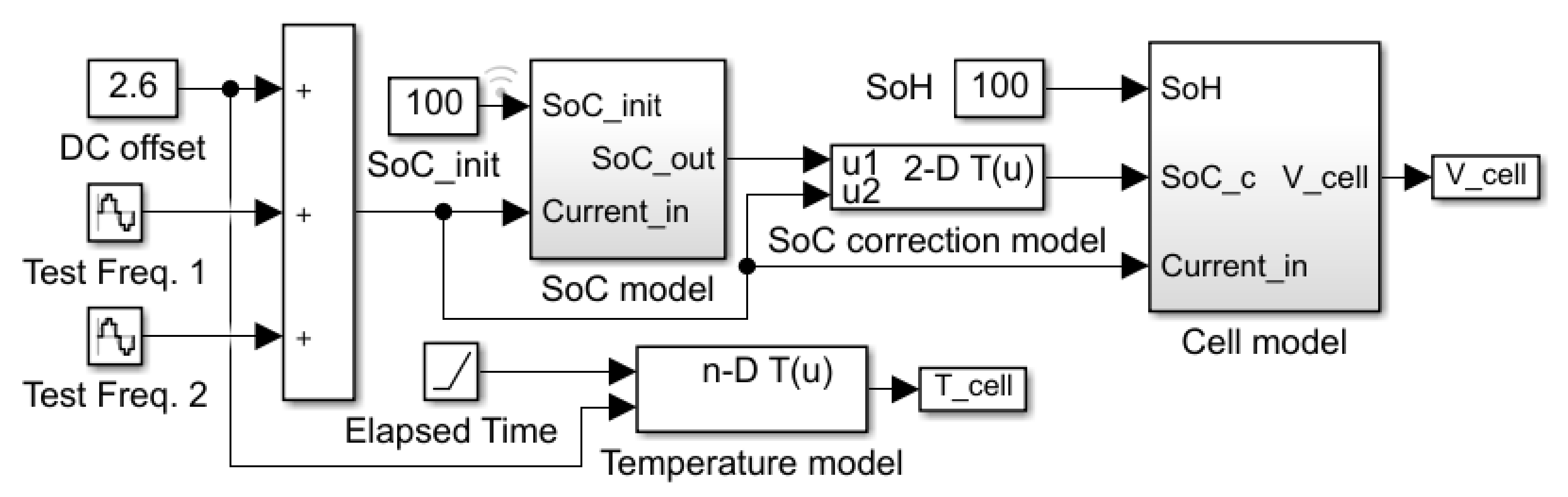
9] monitoring methods. This model estimates the continuous impedance of the cell during discharge for state monitoring. In particular, the cell impedance when a multi-sine signal is applied to the cell operating current is simulated. To output cell impedance, the simulation model considers cell SoC, SoH, cell temperature, and operating current.
It takes much time to measure battery cells under different conditions. It generally takes several hours to measure cell behavior during only one charge and discharge cycle and rest between them. In addition, it can take months for cells to be measured in different SoHs. Nevertheless, in most cases a number of cells must be prepared under different conditions (SoC, SoH, temperature, etc.). Cell simulation models greatly reduce the cost of experiments. In addition to the cost of purchasing experimental devices and cells, the use of models can save time for each cell state to be set. This is because simulation results are displayed simply by entering the parameters of each cell state. The results of the cell state estimation algorithm can be compared in a short time with simulations under different conditions before being measured as an experiment. In this paper, a simulation model is created that outputs the cell voltage and cell impedance when two test frequencies are superimposed on the cell operating current.
An appropriate modeling method should be selected, as computational time increases due to increased computational effort along with model complexity. The battery models presented in the literature are mainly classified into three main categories: physics-based electrochemical models, electrical equivalent circuit models, and data-driven models. All three categories are described shortly in the following considering their suitability for the intended purpose.
Physics-based electrochemical models [
10,
11,
12]
Electrochemical models of batteries are structurally based on the electrochemical processes and reactions inside the cell. These models describe the physical and chemical processes inside the battery cell in greater detail than other models. Therefore, these battery cell models are the most accurate, but they are highly complex and require sufficient knowledge of the cell’s electrochemical processes. For these models to be used in practical applications, very detailed knowledge of the battery cell to be modeled is required as battery-related parameters (e.g., electrode thickness, electrolyte initial salt concentration, total heat capacity, etc.) must be known. Moreover, as these models contain a large number of nonlinear differential equations, the simulation process is time-consuming.
As an alternative to the physics-based modeling method, nonlinear system identification procedures of black-box and gray-box models are used. Electrical equivalent circuit models called gray-box models and data-driven models called black-box models can be classified as empirical models. Empirical models use experimental data to predict battery response. Transfer functions and equations by curve fitting can be used, as well as fuzzy logic and artificial neural networks (ANN).
Data-based models belong to the black-box model. It is not necessary to understand the reaction mechanism and characteristics inside the battery cell. Therefore, data-driven approaches are advantageous for estimation of systems for which mathematical models are unknown, have high uncertainty, cannot be modeled by empirical equations, or are not suitable for analysis [
13]. Fuzzy logic controllers [
14], support vector machines (SVM) [
15], genetic algorithms (GA) [
16], and neural network (NN) algorithms [
17] are used in black-box models. Estimation accuracy is highly dependent on the training data set and training method.
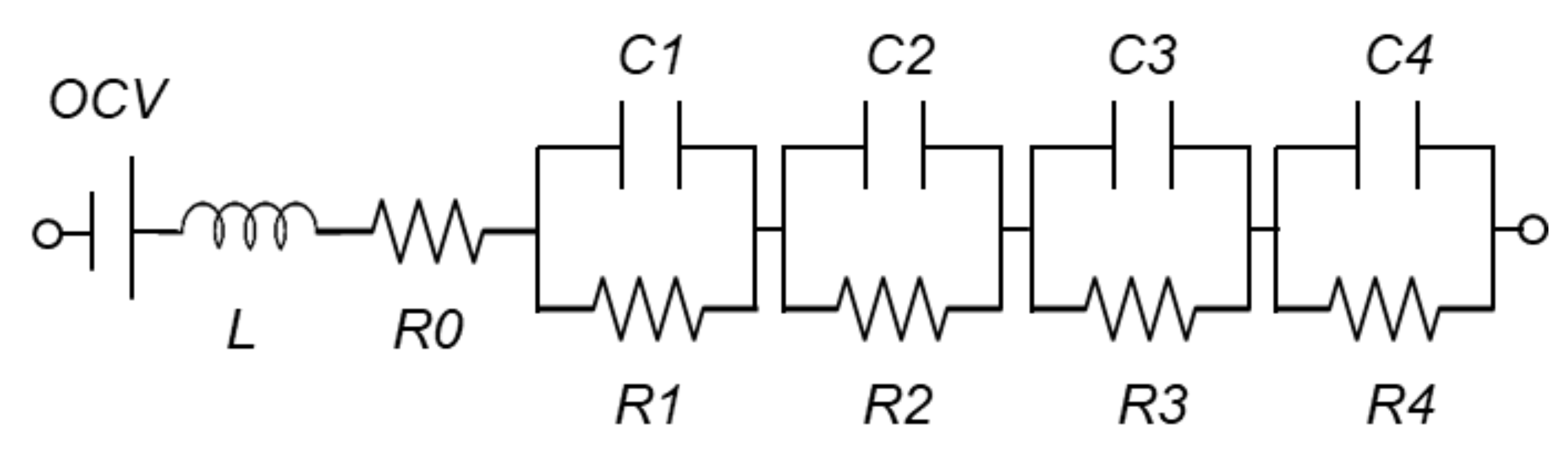
ECMs are also called gray-box models. One important advantage of the gray-box approach is the reduced complexity compared to physics-based electrochemical models. Although the internal electrochemical state of a battery cell is not clearly known, gray-box modeling provides a fast and accurate simulation, suitable for estimating system dynamics and frequency response. The ECMs use linear passive elements that consider the electrical characteristics of the battery cell. These include internal ohmic resistance, polarization resistance, polarization capacitance, inductance, constant phase element, etc. [
18]. There are various models of ECM depending on the trade-off between required accuracy and computation time. The parallel connection of resistance and capacitance, called the RC element, is one of the most common elements in electrochemical impedance modeling. Randles et al. established an impedance model structure called the so-called Randles circuit [
19,
20,
21]. Depending on the shape of the measured cell impedance spectrum, it also includes series ohmic resistance, Warburg diffusion elements, and several RC elements [
22,
23,
24]. In addition, if the standard RC network is not suitable for simulating battery characteristics over the entire frequency range, constant phase elements (CPE) are used instead of capacitors in the RC network [
25,
26,
27]. However, oversimplified dynamic models may not include features such as nonlinear equilibrium potential, rate-dependent capacity, and the effects of temperature.
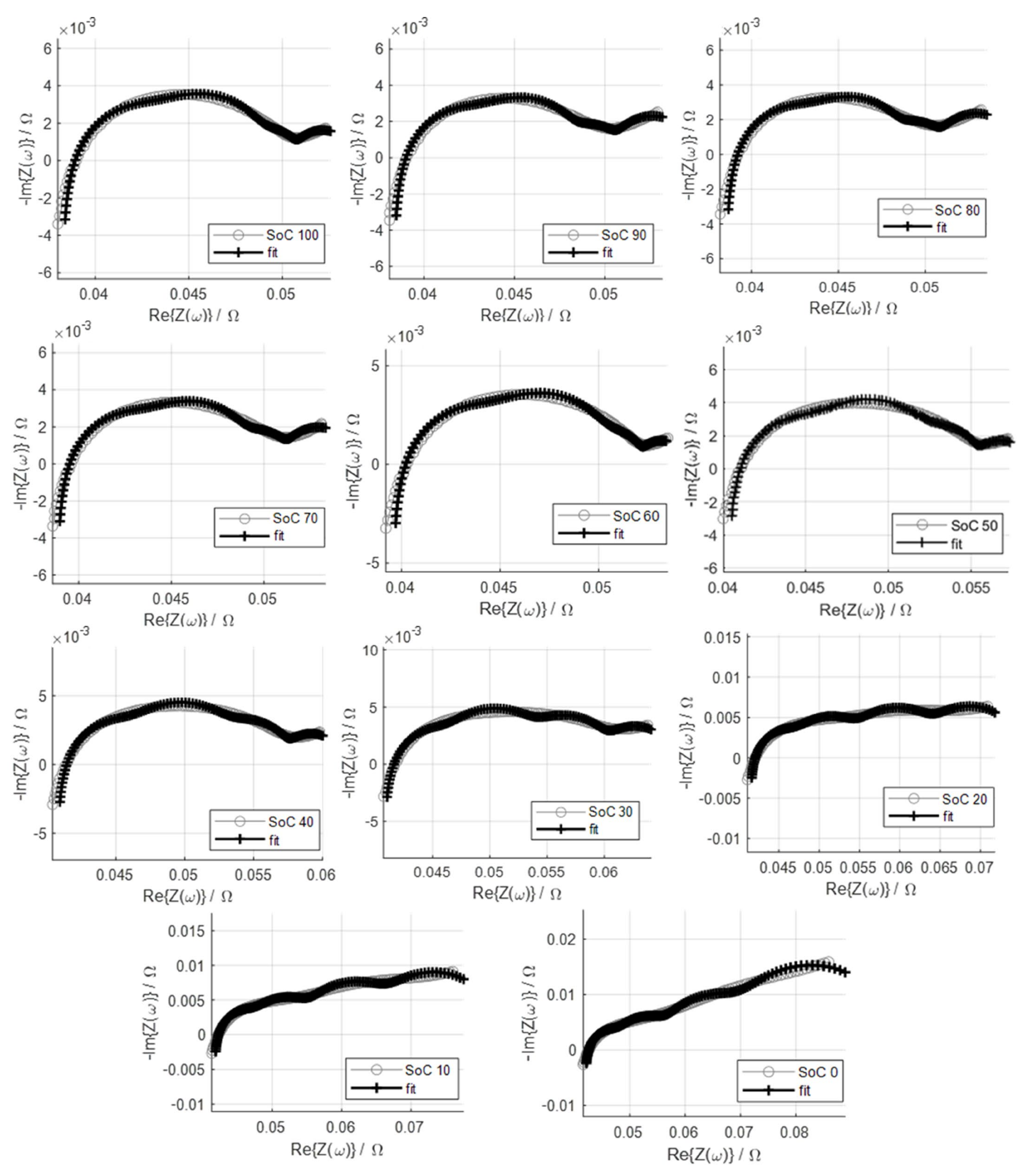
When these circuit elements are considered comprehensively, they exhibit similar properties to those in the battery cell operation process, but the individual physical properties cannot be explained in detail. Therefore, parameter values cannot be measured by laboratory test methods that separate specific physical properties. Instead, the optimization process allows the value of each element to be fitted so that the model prediction matches the measured cell data as well as possible. This process is called system identification. Measured impedance data are fitted to an equivalent circuit representing the physical processes occurring in the system. Fitting of the impedance spectrum must be performed on both the imaginary and the real parts of the data. This can be achieved by complex nonlinear least squares (CNLS) fitting. The fit accuracy is used to determine whether the proposed impedance model and the obtained fitting parameters are suitable for the purpose.
Electrochemical impedance spectroscopy (EIS) is a non-invasive analysis technique for measuring battery cell parameters that establish model structures due to cell SoC, SoH, aging, temperature, internal defects, etc. [
28]. EIS is based on the fact that electrochemical loss processes occur over a wide range of frequencies [
29], and as each process has its own time constant [
30], EIS can isolate most of these processes [
31]. EIS measurements are performed in a wide frequency range from several kHz to several mHz to obtain a characteristic impedance spectrum [
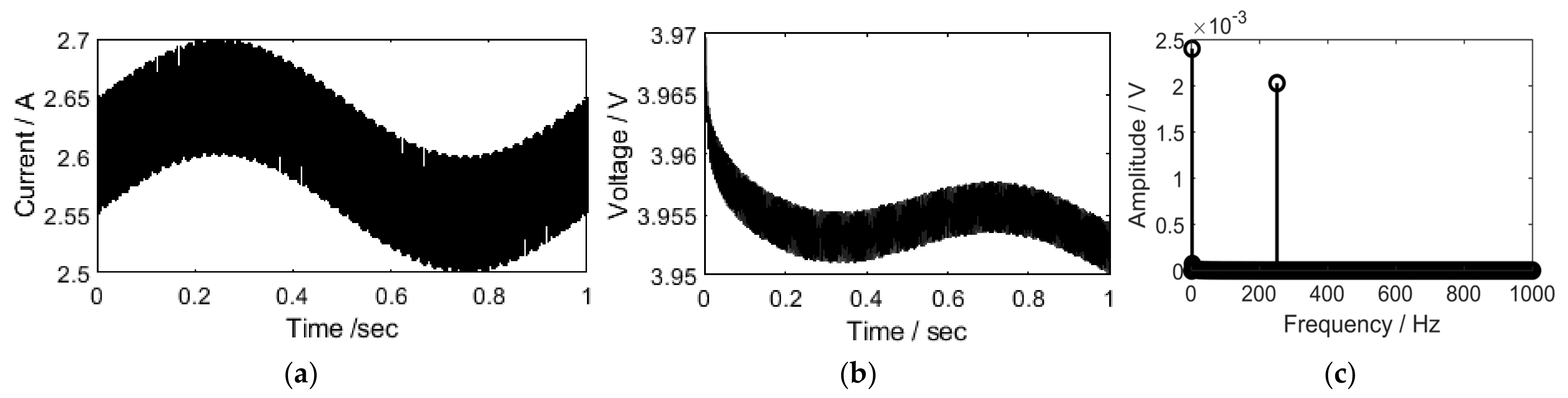
32]. If multiple frequencies are applied simultaneously, this measurement time can be shortened, and this method is called multi-sine EIS [
9].
EIS measurements include applying small sinusoidal voltage or current signals to electrochemical cells and measuring system reactions in amplitude and phase (real and imaginary parts) to determine cell impedance. The complex impedance contains information on the amplitude and phase between the voltage and current signals for each different frequency. If the current
of the battery cell is given by Equation (1), and the voltage
is measured as Equation (2), the cell impedance Z can be obtained as Equation (3).
where
is direct current (DC) bias,
is the amplitude of the excited test frequency f,
is the offset voltage,
is the amplitude of the output voltage, and
is the phase difference.
As shown in Equation (3), the electrochemical impedance of a battery cell is a frequency-dependent complex number characterized by its modulus and phase angle . Another expression is given as the real and imaginary parts of the complex impedance.
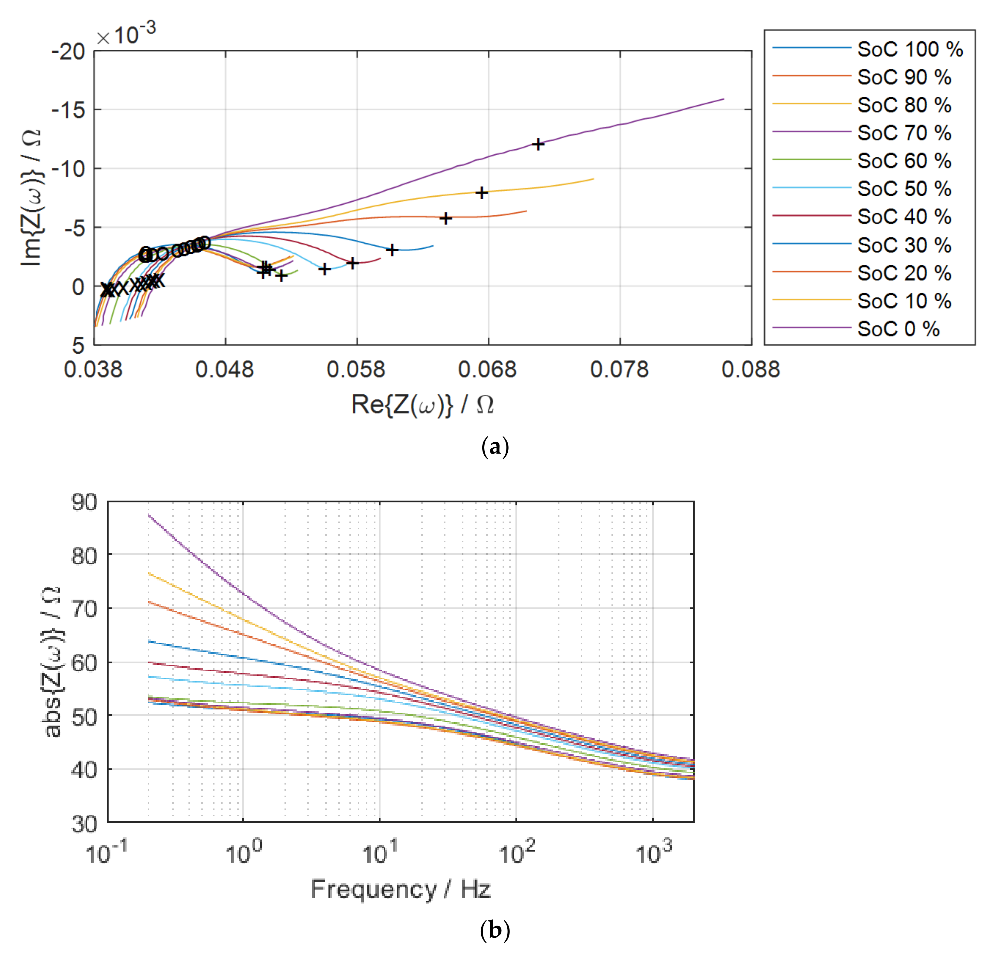
In this paper, an equivalent circuit model for Li-ion battery cells is developed in the MATLAB/Simulink environment. Therefore, the proposed model can be easily connected to other circuit blocks in MATLAB/Simulink. Each element value of the equivalent circuit model is determined by the EIS measured in different cell SoCs.
In
Section 2, the proposed model is presented. Selection of model parameters and details of each simulation block are described. In
Section 3, the model is validated with simulation results under various conditions compared to the measurement, and
Section 4 deals with conclusion and discussions.


