Article

Enhancing the LCO 18,650 Battery Charging/Discharging Using Temperature and Electrical Based Model

by
Abdullah Al-Refai
1,*,
Abedalrhman Alkhateeb
1,* and
Zakariya M. Dalala
2
1
Software Engineering Department, King Hussein School of Computing Science, Princess Sumaya University for Technology, Amman P.O. Box 1438, Jordan
2
Department of Energy Engineering, School of Natural Resources Engineering and Management, German Jordanian University, Amman P.O. Box 35247, Jordan
*
Authors to whom correspondence should be addressed.
Batteries 2022, 8(11), 199; https://doi.org/10.3390/batteries8110199
Submission received: 6 September 2022 / Revised: 2 October 2022 / Accepted: 7 October 2022 / Published: 26 October 2022

Abstract

:
Lithium-ion batteries are commonly used in electric vehicles, embedded systems, and portable devices, including laptops and mobile phones. Electrochemical models are widely used in battery diagnostics and charging/discharging control, considering their high extractability and physical interpretability. Many artificial intelligence charging algorithms also use electrochemical models for to enhance operation efficiency and maintain a higher state of health. However, the parameter identification of electrochemical models is challenging due to the complicated model structure and the high count of physical parameters to be considered. In this manuscript, a comprehensive electrochemical lithium-ion battery model is proposed for the charging and discharging processes. The proposed model accounts for all dynamic characteristics of the battery, including the cell open-circuit voltage, cell voltage, internal battery impedance, charging/discharging current, and temperature. The key novelty of the proposed model is the use of simulated open-circuit voltage and simulated changes in entropy data instead of experimental data to provide battery voltage and temperature profiles during charging and discharging cycles in the development of the final model. An available experimental dataset at NASA for an LCO 18,650 battery was utilized to test the proposed model. The mean absolute error for the simulated charging cell voltage and temperature values were 0.05 V and 0.3 °C, compared with 0.14 V and 0.65 °C for the discharging profile. The simulation results proved the effectiveness and accuracy of the proposed model, while simplicity was the key factor in developing the final model, as shown in the subsequent sections of the manuscript.

1. Introduction

Lithium-ion batteries, as one of the most advanced portable power sources, have drawn considerable attention in the past few years. As shown in Figure 1, the need for Li-ion batteries is increasing rapidly [1]. They are used in many applications, most commonly in portable electronics and electric vehicles (EV). The wide use of lithium-ion batteries nowadays is due to the advantages they hold such as a higher energy density and voltage capacity and a lower self-discharge rate. There are several types of lithium-ion batteries on the market, including lithium-ion cobalt oxide ( LiCoO 2 ), lithium manganese oxide (Li Mn 2 O 4 ), lithium iron phosphate (LiFe O 4 ), and lithium polymers (LiPo). Charging and discharging these batteries are complex processes that depend on their topology and certain physical aspects, including electrical and thermal aspects. Due to the significance of these factors, an extensive quantity of research can be found in recent years to improve the electrical and thermal modeling of lithium-ion batteries with different levels of accuracy and complexity.
The electric models aim to simulate the behavior of the electric quantities (cell voltage, state of charge (SOC), state of health (SOH), etc.) at the external terminals of the battery based on the charging or discharging current. In contrast, the goal of the thermal models is to simulate the temperature distribution of the battery cell. An enormous quantity of research can be found in the literature on electric models with varying degrees of complexity and efficiency. They capture the battery electric quantity behavior for specific motivations from performance estimation to circuit simulation.
Furthermore, lithium-ion battery modeling is commonly based on physical, mathematical, or electrical approaches. The literature contains considerable research on modeling using one of the previously mentioned approaches. The electrochemical models [2,3,4,5,6,7] are a physical approach that is mainly used to optimize the physical aspects of batteries, classify the fundamental method of power generation, and connect battery design parameters. These models reproduce the battery temperature profile based on the current and cell voltage during the charging and discharging process. These models are described by one-, two-, three-, or four-dimensional partial differential equations (PDEs). However, they are complex numerical algorithms, consuming simulation time and battery-specific information that is challenging to acquire due to the nature of the battery technology [8].
Mathematical models [9,10,11,12,13,14,15,16,17] are mostly too abstract to predict system-level behavior, such as battery efficiency or capacity, and are still useful to system designers and only work for specific applications. However, these models do not have cell voltage profiles during the charging and discharging process. This information is crucial to optimizing circuit and system performance [18,19]. These models provide inaccurate results on the order of 5–20% error.
Electrical models [20,21,22,23,24,25,26,27,28,29,30,31,32,33,34,35] use electrical equivalent circuits for lithium-ion batteries. Moreover, these circuits combine voltage sources, resistors, and capacitors. They are very useful and easy to handle by electrical engineers. Their accuracy lies at around 1–5% error. These models reproduce the cell voltage profile during the charging and discharging process by only monitoring the battery temperature limits. However, they do not provide the battery temperature profile during the charging and discharging process.
The developed models are utilized to describe and understand the fundamental mechanisms of power generation and energy storage and generate interrelated descriptive dynamics for the battery’s design parameters, such as the cell voltage, temperature, and charging current [4,6,7]. However, mathematical and electrochemical models provide limited accuracy for predicting an actual battery’s energy profile, thus limiting their use to narrow design applications. On the other hand, electrical models are well-known for generating more accurate I–V information results than mathematical and electrochemical models, where circuit simulators can be readily used to develop electrical models and provide simulation results [8,9].
Scant literature discussed the electrothermal combined model to simulate the battery voltage and temperature variation. In [36], a scale electrothermal model was presented for a LiFePO4/graphite lithium-ion battery to improve the physical emulation of the battery in a hardware-in-the-loop (HIL) process. This model was based on three scaling factors (voltage scaling, current scaling, and time scaling). They were used to simulate the real-time behavior of the battery in the HIL. The open-circuit voltage was calculated depending on the discharge capacity experimental data measured at several temperatures. This model provided acceptable simulation results for LiFePO4/graphite lithium-ion batteries. However, this work needed many specific experimental battery parameters and focused on the HIL. Lunguo Chen proposed an electrothermal model that estimates the temperature based on joint Kalman filtering. The work reported discharging cycle results with an error of the service temperature within ±1 °C [37]. In our proposed electrothermal model based on the merger of an electrical model and one-dimensional numerical model, the service charge error for the discharging cycle was within the same range, and additionally, the model results in the error of the charging cycle were within ±0.8 °C.
This work’s motivation is to present an electrothermal model that reproduces the battery voltage and temperature during the charging and discharging process. This model contains two approaches: the first is an electrical model that provides the battery voltage based on the charging and discharging current. In this approach, the open-circuit voltage and battery impedance are calculated based on the state of the charge. The second approach is the one-dimensional numerical model that provides the battery temperature based on the current (charging and discharging), the calculated open-circuit voltage (calculated in the first approach), and the battery voltage (calculated in the first approach).
The paper is structured as follows: In Section 2, the methodology and our model are presented. Section 3 presents the results and discussions. Finally, Section 4 presents the conclusion.

2. Methodology

2.1. Electrical Battery Model—Overview and Governing Equations

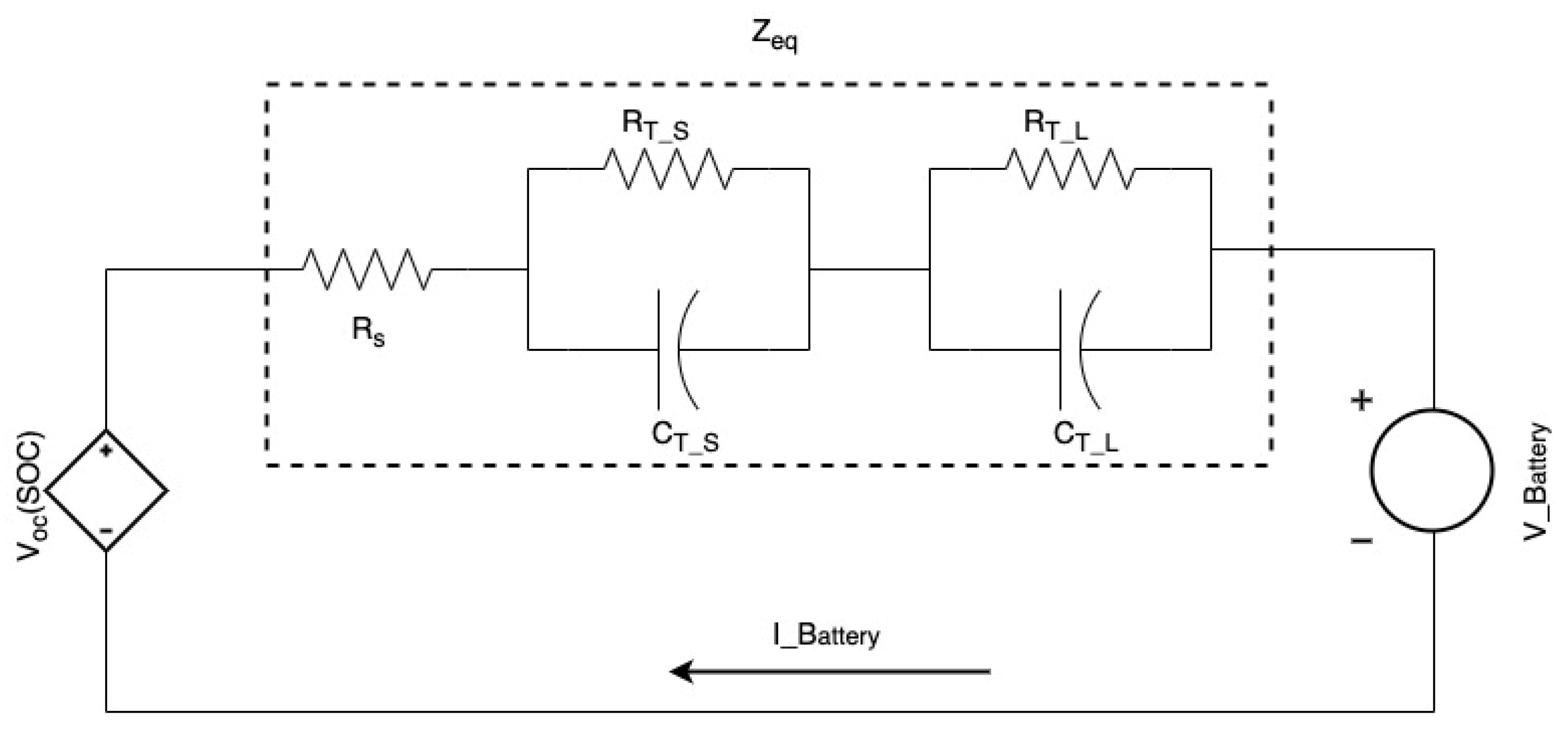
The battery cell voltage is calculated based on the open-circuit voltage, internal impedance, and voltage compensation offset, as shown in Equation (1). The internal impendence represents the combination of the internal resistance and the reactance [8,38,39]. In [8], ten brand-new TCL PL-383562 polymer Li-ion batteries with 850 mAh were tested with appropriately spaced pulse discharge currents (80, 160, 320, and 640 mA). The experimental results for the TCL PL-383562 batteries were used to extract all the parameters in their model:
V B a t t e r y   = V oc I B a t t e r y     Z eq + Δ E ( T )
where:
V B a t t e r y is the battery cell voltage in volts.
V oc is the battery open-circuit voltage in volts.
I B a t t e r y is the charging/discharging current in ohms.
Z eq is the battery equivalent internal impedance in ohms.
Δ E ( T ) is the voltage compensation offset due to battery temperature variation (in Kelvin).
It was optimized using a grid search, and the value 0.2 was selected for the proposed work.
Furthermore, the battery open-circuit voltage is mainly dependent on the state of the charge of a battery. Equation (2) [8] shows the battery open-circuit voltage calculation:
V oc S O C = 1.031 × e 35   ×   S O C + 3.685 + 0.2156 × S O C 0.1178 × S O C 2 + 0.3201 × S O C 3
where:
V oc S O C is the battery open-circuit voltage depending on the SOC.
SOC is the battery state of charge, which represents the percentage of the capacity remaining to the nominal capacity of a battery (0% = empty charge; 100% = full charge). The charging/discharging current state denoted by the S O C is calculated based on the initial charging state of the battery ( S O C init ). Since the battery voltage and state of change are cumulative statuses, this can be seen in Equation (3) [40,41,42]:
S O C = S O C init +   η     I B a t t e r y / C   d t
where S O C init is the initial SOC value of a battery, η is the Coulombic efficiency constant ( η = 1 for discharge and η ≤ 1 for charge), C is the nominal capacity, and I B a t t e r y is the battery charging current (where I B a t t e r y is positive when discharging a battery and negative when charging a battery) [42,43]. The Coulombic efficiency is used to determine the released battery capacity. It represents the ratio of the discharge capacity after a full charge and the charging capacity of the same cycle [44].
In [45], a detailed physical lithium-ion battery impedance model was introduced. This model introduced the relationship between the obtained bulk resistances, the charge transfer reaction, an interface layer, diffusion process, and battery characteristics. A simplified internal battery impedance was presented in [8]. Figure 2 illustrates the battery equivalent internal resistance. Its circuit contains a series resistor ( R s ) and two resistor–capacitor (RC) circuit networks consisting of R T _ S , C T _ S , R T _ L , and C T _ L , which are responsible for the direct voltage drop in the battery terminal voltage. Furthermore, the short- and long-time transients in battery internal resistance are represented by the components of RC networks [8]. Equations (4)–(8) [8] show the battery equivalent internal resistance calculation. This equivalent resistance is primarily dependent on the state of charge of a battery.
R s   S O C = 0.1562   ×   e ( 24.37   ×   S O C ) + 0.07446
R T _ S   S O C = 0.3208   ×   e ( 29.14   ×   S O C ) + 0.04669
C T _ S   S O C = 752.9   ×   e ( 13.51   ×   S O C ) + 703.6
R T _ L   S O C = 6.603   ×   e ( 155.2   ×   S O C ) + 0.04984
C T _ L   S O C = 6056   ×   e ( 27.12   ×   S O C ) + 4475

2.2. Numerical Battery Temperature Model

Electrochemical dynamics have been investigated in the literature for different batteries, and different mathematical models with varying complexities and accuracies have been proposed. Battery temperature, as a vital model input, has also been engaged in several studies where heat dissipation during the charging mode is modeled. A temperature model is utilized to illustrate the battery behavior and represent its temperature profile [3,4,6,7].
The authors in [46] proposed a thermal characteristic estimation model that balances the energy relation of battery systems. The study formulated an equation that uses all the elements that can affect the temperature change inside the cell battery, including irreversible ohmic heating, reversible entropic heating, heat from the phase change of the active materials, reaction heat, and heat from mixing. In [46,47,48,49], Al Hallaj et al. simplified Bernard’s heat generation, which is an accounting of the irreversible ohmic heating and reversible entropic heat sources. According to Al Hallaj’s work, the cell temperature profile of lithium-ion batteries can be calculated as shown in Equation (9):
MC P dT d t = q generation h A ( T T A )
where:
M is the cell mass.
C P is the specific heat capacity.
q generation is the entire heat generation rate.
h is the heat transfer coefficient.
A is the battery cell area.
T is the battery cell surface temperature.
T A is the ambient temperature.
The overall heat generation ( q generation ) is calculated by adding the irreversible ( q irreversible ) to the reversible ( q reversible ) sources of heat generation, presented in Equation (10) [46], while the irreversible heat produced by the cell during the charging cycle is defined in Equation (11) [46]:
q generation = q irreversible + q reversible
q irreversible = I B a t t e r y     ( V B a t t e r y V oc )
where:
I B a t t e r y is the battery charging current.
V B a t t e r y is the cell voltage.
V oc is the open-circuit voltage of the battery cell.
In the proposed model, the outcome of the simulated V oc in Chen and Mora’s model from Equation (2) is used in Equation (11). We applied this V oc to evaluate both Al Hallaj’s model and the proposed model.
Changes in entropy (dVoc/dT) can be used to determine the reversible heat produced by the cell throughout the charging/discharging cycle, as illustrated in Equation (12) [46]:
q reversible = I B a t t e r y   ×   T   ×   dVoc / dT

2.3. The LCO 18,650 Battery Charging/Discharging Model

In this work, the resulting cell voltage profile and battery open-circuit voltage from the electrical model were fed to the battery numerical model for both charging/discharging experimental current to calculate the battery temperature profile. The model considers both charging/discharging entropies. In [50], the entropy changes were measured using an electrochemical thermodynamic measurement system (ETMS) in complete lithium-ion batteries. Furthermore, the LCO 18,650 battery was used to evaluate the proposed model, and the experimental entropy results in [50] were analyzed to provide polynomial equations, as illustrated in Equations (13)–(27) across the 0–100% SOC range, to be used in the proposed model.
The LCO 18,650 battery charging equations:
If SOC ≤ 0.1
dVoc/dT = (1600 × SOC2 – 140 × SOC − 20)/1000
Else if SOC ≤ 0.21
dVoc/dT = (757.576 × SOC2 − 162.121 × SOC − 9.36364)/1000
Else if SOC ≤ 0.34
dVoc/dT = (−38.4615 × SOC2 + 98.0769 × SOC − 28.9)/1000
Else if SOC ≤ 0.44
dVoc/dT = (333.333 × SOC2 – 140 × SOC + 9.06667)/1000
Else if SOC ≤ 0.54
dVoc/dT = (−3833.33 × SOC2 + 3436.67 × SOC − 758)/1000
Else if SOC ≤ 0.65
dVoc/dT = (696.97 × SOC2 − 811.212 × SOC + 214.818)/1000
Else if SOC ≤ 0.78
dVoc/dT = (109.89 × SOC2 − 64.8352 × SOC − 22.2857)/1000
Else if SOC ≤ 0.89
dVoc/dT = (727.273 × SOC2 − 1050.91 × SOC + 371.236)/1000
Else if SOC ≤ 1
dVoc/dT = (−1396.1 × SOC2 + 2665.91 × SOC − 1254.81)/1000
The LCO 18,650 battery discharging equations:
If SOC ≤ 0.2
dVoc/dT = (300 × SOC2 − 60 × SOC − 55)/1000
Else if SOC ≤ 0.4
dVoc/dT = (50 × SOC2 + 5 × SOC − 58)/1000
Else if SOC ≤ 0.59
dVoc/dT = (−362.573 × SOC2 + 411.579 × SOC − 154.62)/1000
Else if SOC ≤ 0.82
dVoc/dT = (−243.742 × SOC2 + 387.154 × SOC − 181.574)/1000
Else if SOC ≤ 0.89
dVoc/dT = (357.143 × SOC2 − 525 × SOC + 162.357)/1000
Else if SOC ≤ 1
dVoc/dT = (1363.64 × SOC2 − 2286.36 × SOC + 932.727)/1000
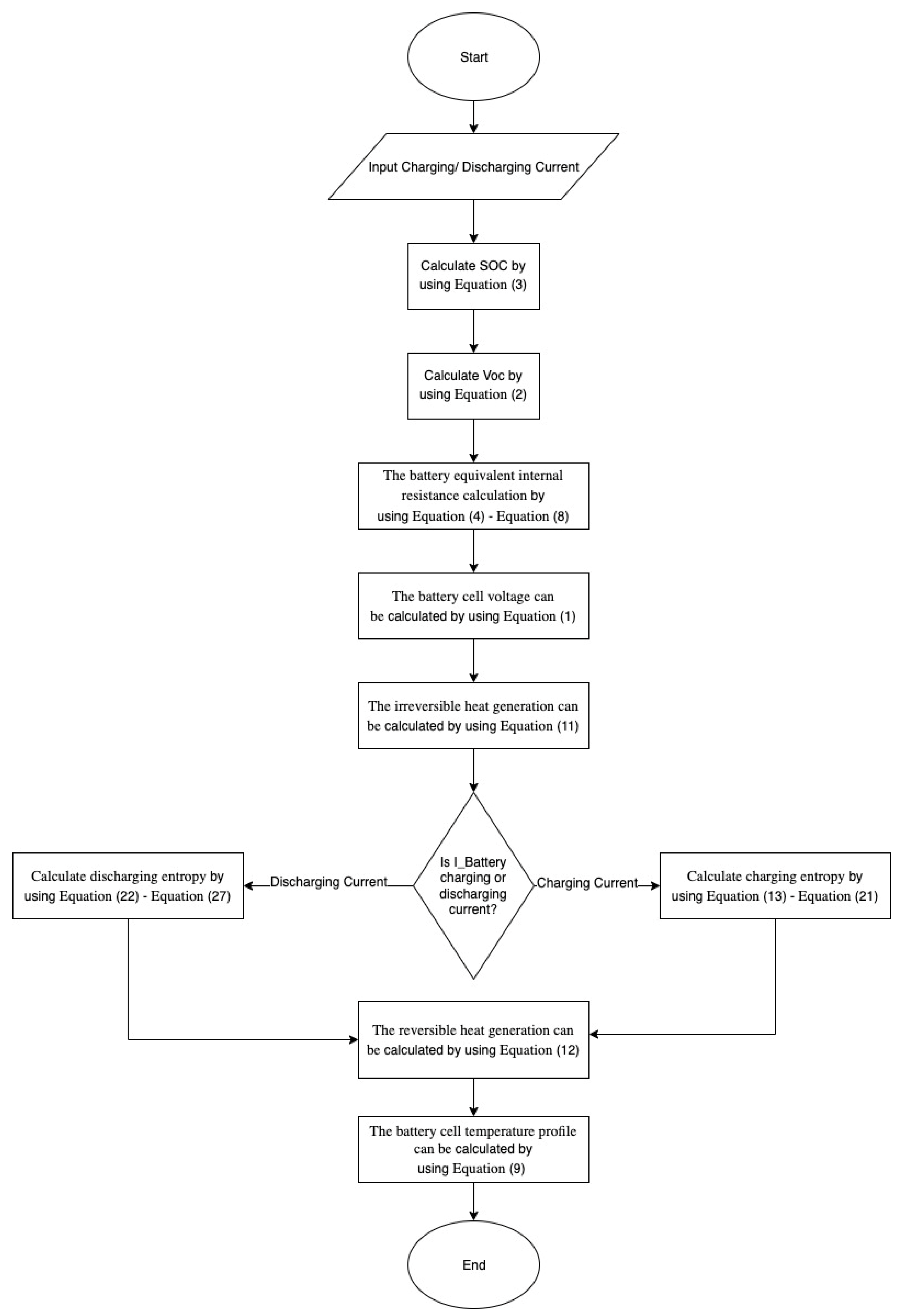
The proposed electrothermal model identifies the temperature profile during the battery charging/discharging cycle, as seen in Figure 3. The final proposed model can be expressed as Equation (28):
MC P dT dt = [ ( I B a t t e r y   ( V B a t t e r y From   Equation   1 Equation   8   V oc Equation   ( 2 ) ) ) + ( I B a t t e r y   × T   ×   dVoc / dT ) ] h A ( T T A )
As shown in Figure 3, the proposed model starts with calculating the SOC based on the input charging/discharging current using Equation (3). The SOC is fed to Equation (2) to calculate the Voc. Then, the Zeq is calculated based on the SOC by using Equations (4)–(8). The simulated Voc and Zeq, combined with the experimental charging/discharging current, are used to calculate the simulated battery cell voltage during the charging/discharging cycle using Equation (1). After that, the model applies Equation (11) to the values of the simulated battery cell voltage, Voc, and the charging/discharging current to calculate the irreversible source of heat generation. The reversible source of heat generations is calculated based on the charging/discharging entropies and the experimental charging current by using Equation (12). Both the reversible and irreversible sources of heat generation are fed to Equation (10) to calculate the entire heat generation rate. Finally, the battery temperature profile can be extracted from Equation (9) based on the entire heat generation rate.

3. Results

In this work, we applied the proposed model to the experimental dataset publicly available at NASA for an LCO 18,650 battery (B0005 battery dataset). This dataset was tested at the NASA Ames Prognostics Center of Excellency (PCoE) [51]. The proposed model was tested on both charging/discharging cycles and compared against the experimental data. The important battery characteristics for both cycles are provided in this section. The properties and specifications of the battery cell are given in Table 1.
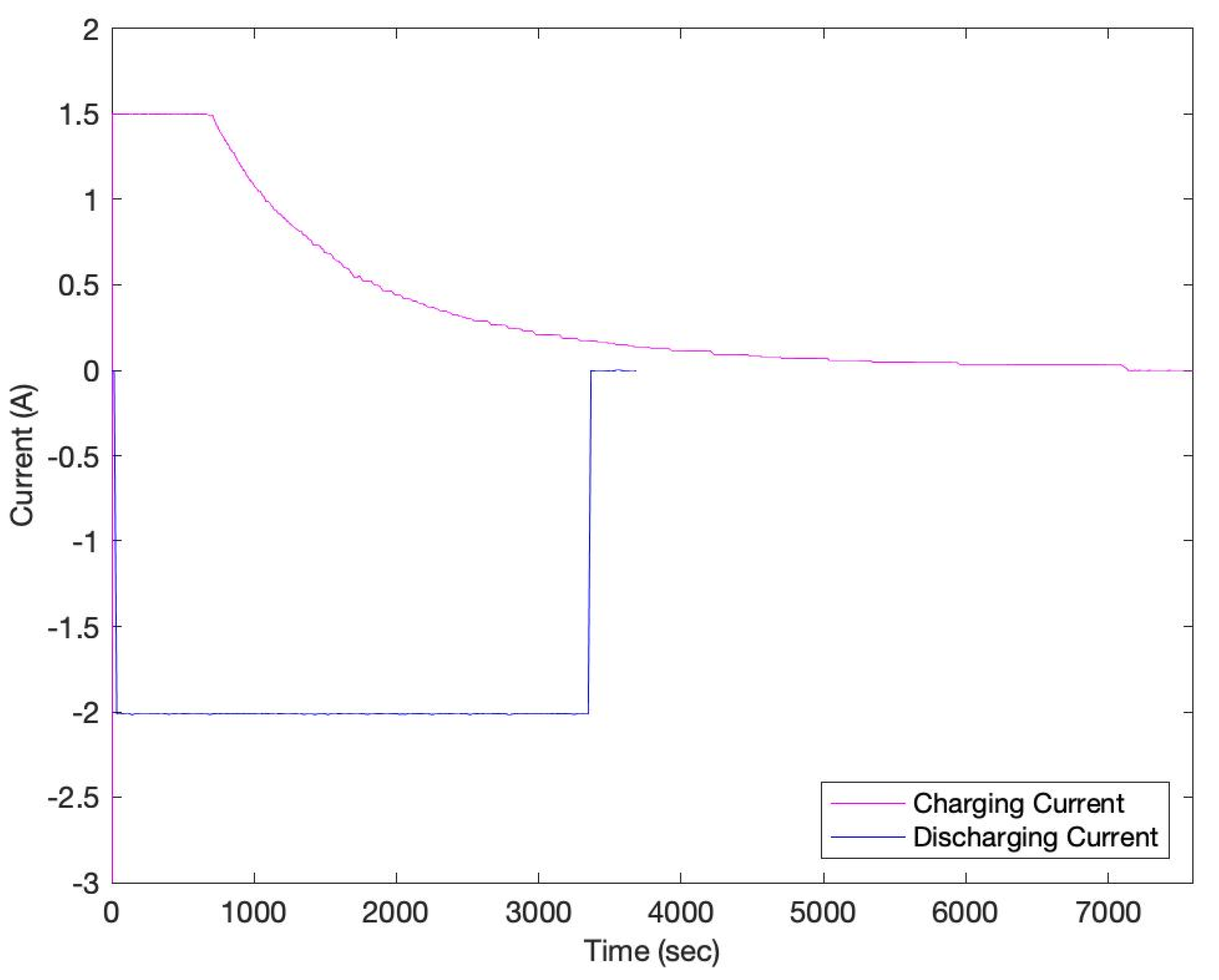
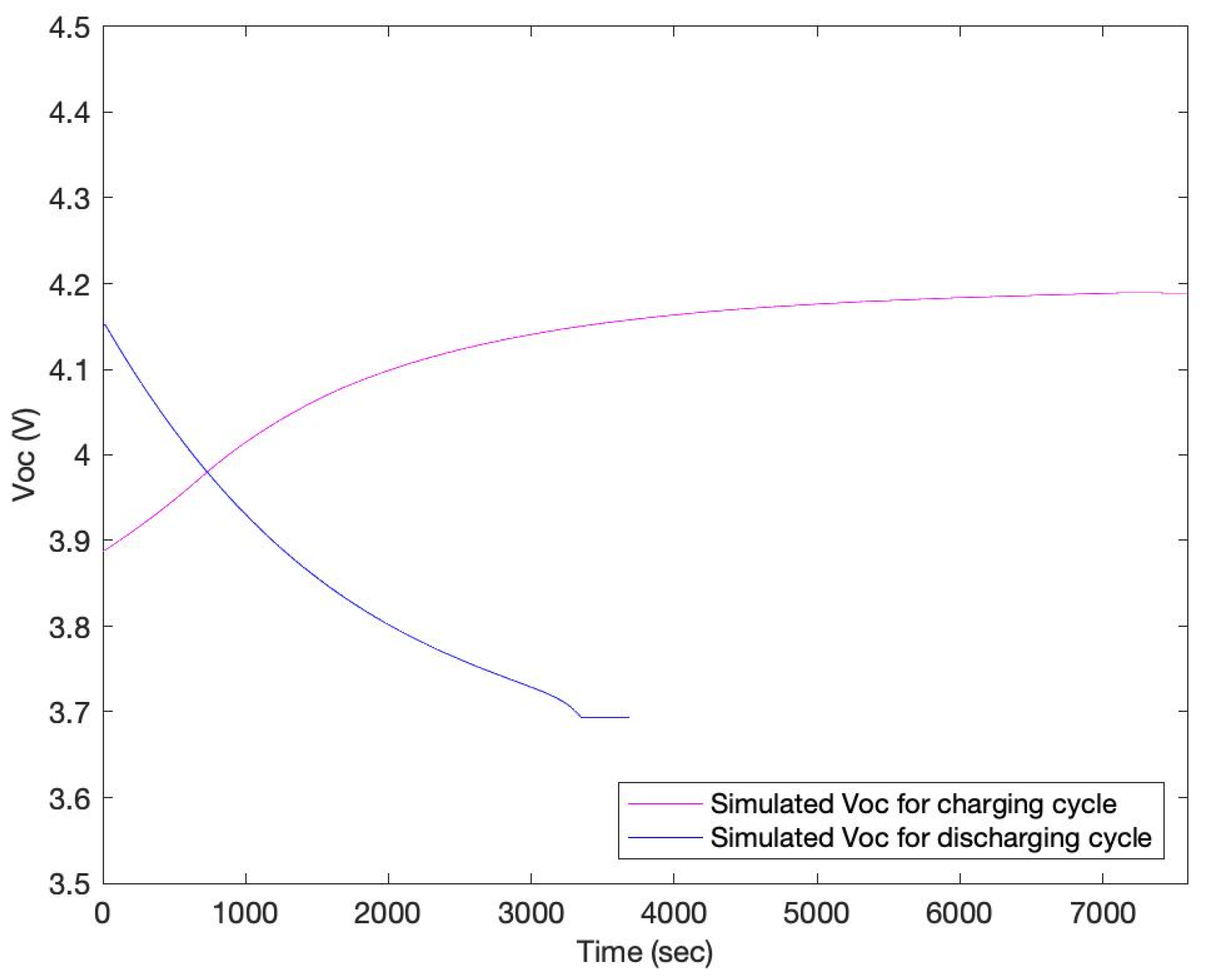
The experimental charging profile of the B0005 battery dataset is shown in Figure 4. The figure shows the result of the constant current—constant voltage (CC-CV) charging technique. The charging cycle started with a CC phase that charged with a constant current equal to 1.5 A. Once the cell voltage reached 4.2 V, the CV phase started. Then, it dropped exponentially until the current almost reached zero. The simulated open-circuit voltage data were used instead of experimental data to provide battery voltage in the proposed model. Figure 5 shows the change in the simulated battery open-circuit voltage over time. It started at 3.9 V and ended at 4.2 V during the charging cycle.
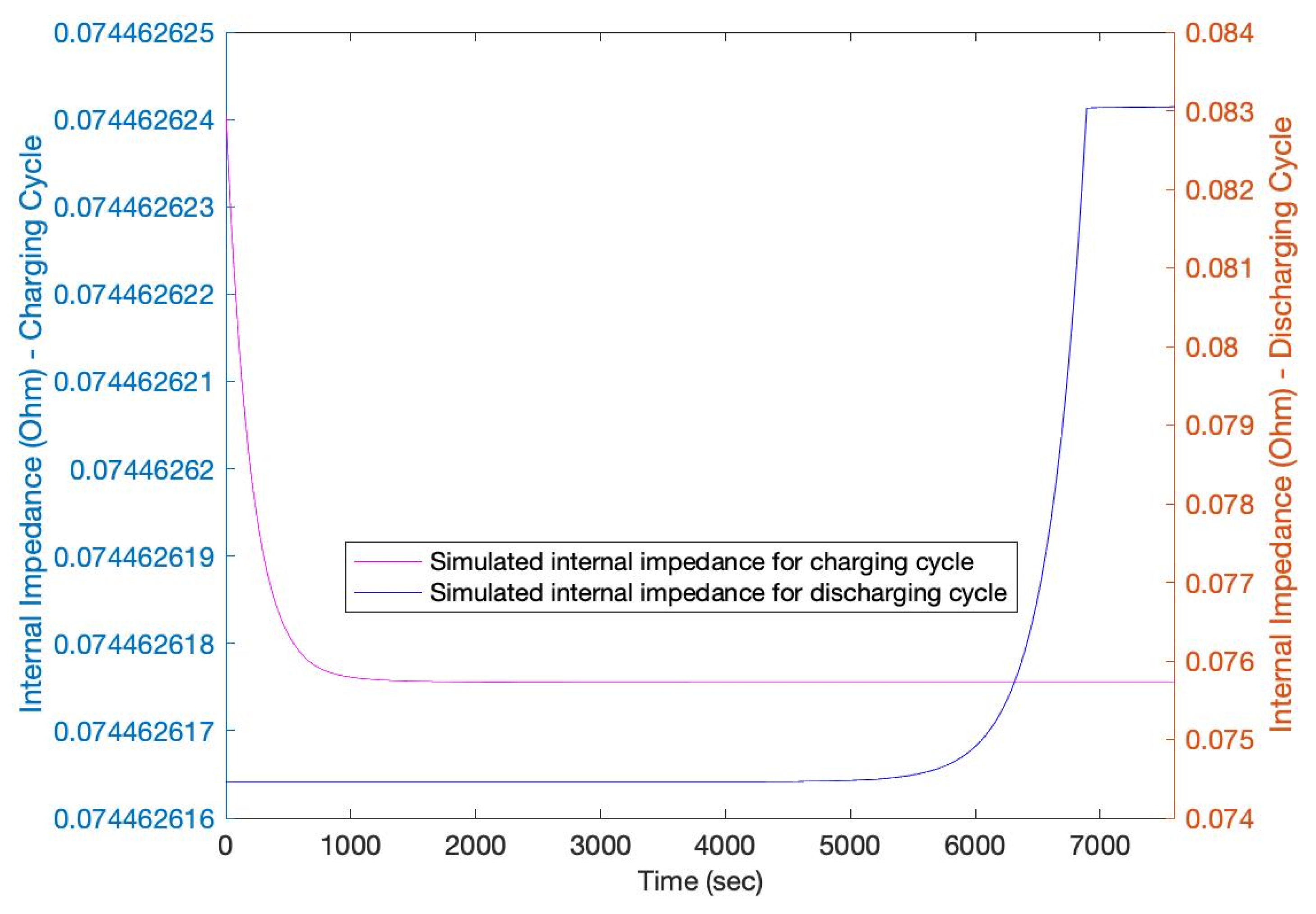
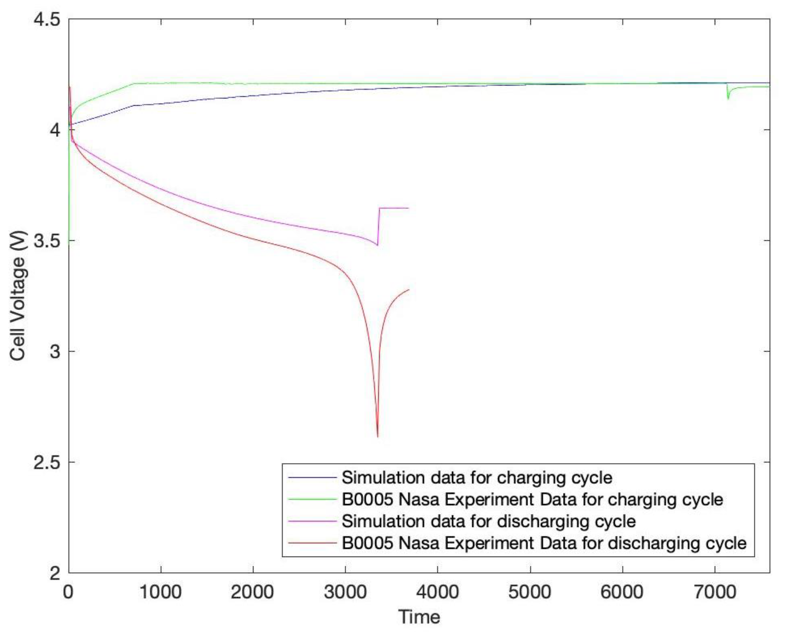
The internal impedance was used to calculate the cell voltage profile. Figure 6 shows the change in the simulated internal battery impedance over time. It was almost fixed during the charging cycle and varied during the discharging cycle. We compared the data from the proposed model to the experimental model for the cell voltage profile during the charging cycle. The comparison revealed that the error in the CC phase was greater than in the CV phase, as illustrated in Figure 7, where the voltage in the CC phase started at 3 V and remained at 4.2 V in the CV phase. The mean absolute error (MAE) and root mean square (RMS) were used to compare the two models. The MAE measures the average magnitude of the errors between the two forecasts without considering the direction. The MAE value was 0.05 V, and the RMS value was 0.06 V, as seen in Table 2.
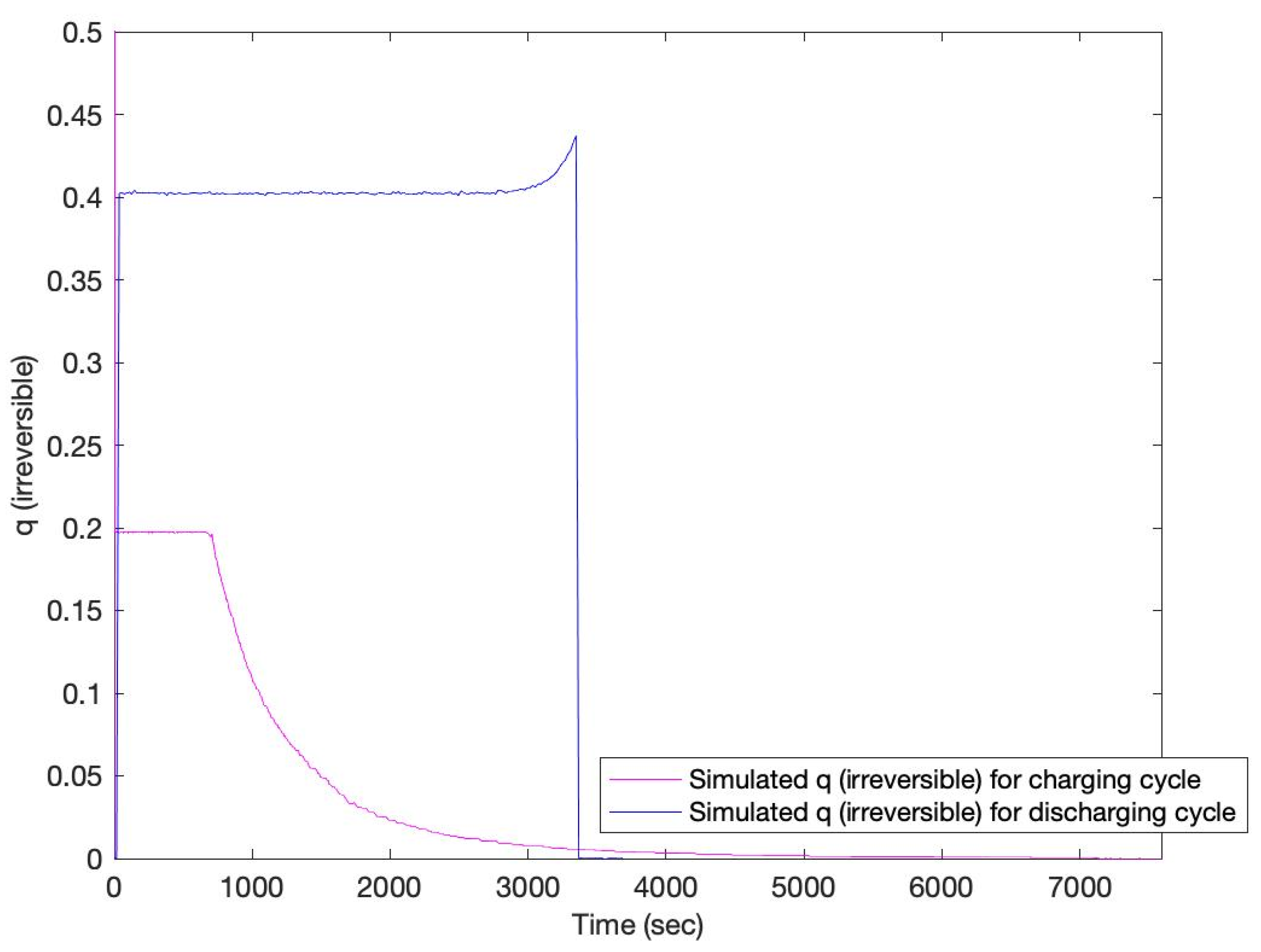
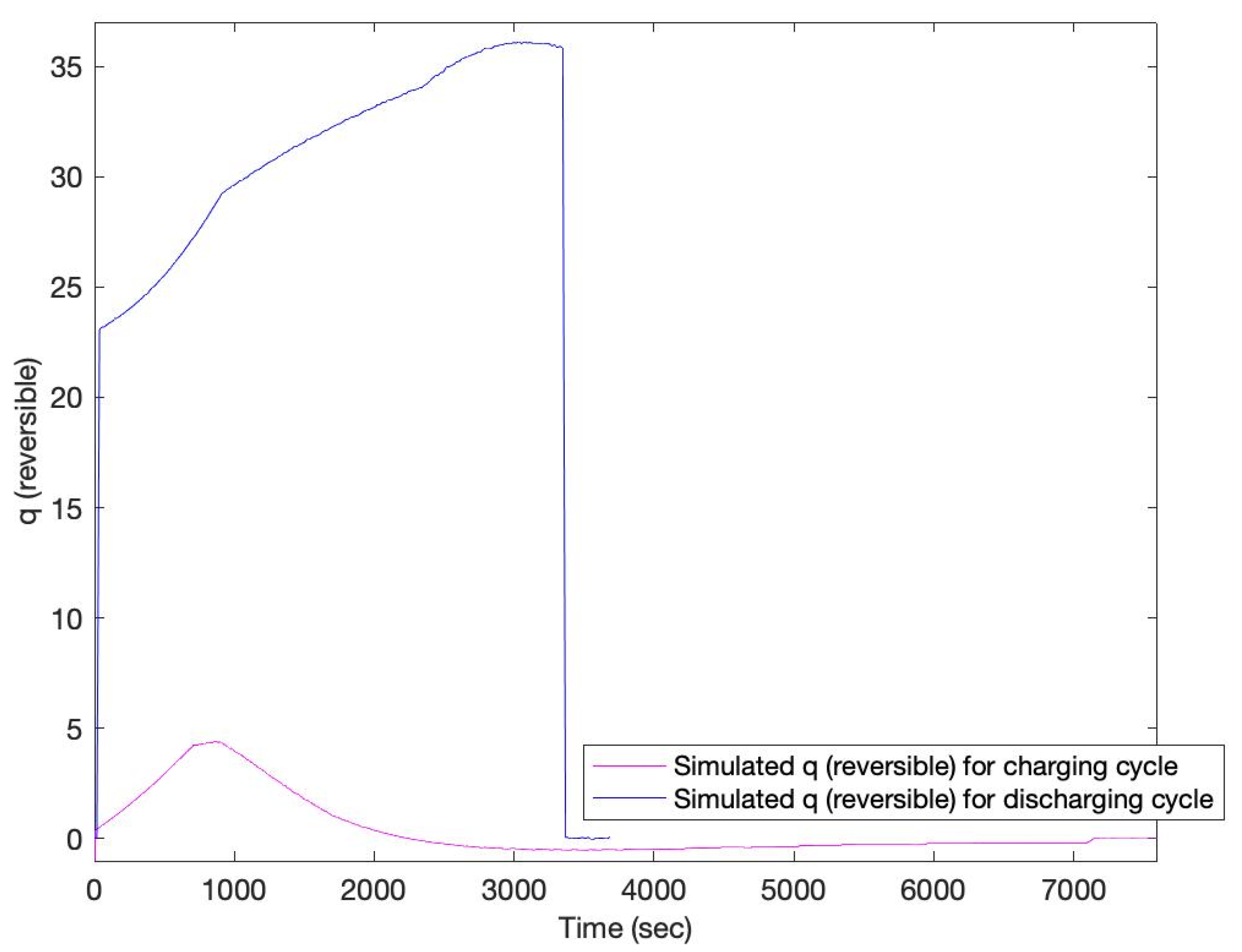
The irreversible ohmic heating and reversible entropic heating were used to calculate the entire heat generation rate, as shown in Figure 8 and Figure 9. The entire heat generation is essential for calculating the battery temperature profile. The charging battery temperature profiles of the proposed and the experimental models are shown in Figure 10. The charging temperature profile started at 25 °C and increased exponentially in the CC phase then decreased exponentially in the CV phase until the end of the charging cycle. The estimated temperature error between the two profiles was within ±0.8 °C. The MAE value was 0.3 °C, and the RMS value was 0.38 °C, as seen in Table 2.
We compared the proposed model’s data and the experimental model’s data for the cell voltage profile during the discharging cycle. The experimental current discharging profile for the B0005 battery dataset is shown in Figure 4, exhibiting the discharging time cutoff at 3700 s. The discharging cycle discharged with constant current equal to 2 A for the whole cycle. At the beginning of the discharging cycle, the cell voltage started at 4.2 V and dropped exponentially until ending at 3.6 V, as seen in Figure 7. In the experimental data, the discharging cycle dropped to 2.5 V after the relaxation time (discharge with 0 A), starting at around 3400 s. That means that the electrical model used in our proposed model worked efficiently during the discharging cycle. However, when the relaxation time started, the voltage did not follow the actual experimental data, which could be a future direction for this work. The MAE value was 0.14 V, and the RMS value was 0.2 V, as seen in Table 2. The error increased in the discharging cycle, where most errors happened during the relaxation time.
Figure 5 shows the change in the simulated battery open-circuit voltage over time. It started at 4.2 V and dropped exponentially to end at 3.6 V during the discharging cycle.
The discharging battery temperature profiles of the proposed model’s data and the experimental model’s data are shown in Figure 10. The discharging temperature profile started at 24 °C and increased exponentially until the end of the cycle. The error of the estimated temperature between the two profiles was between 0 and 1.3 °C during the discharging cycle and increased a little bit during the relaxation time due to the carry error for the cell voltage. The MAE value was 0.65 °C, and the RMS value was 0.89 °C, as seen in Table 2.
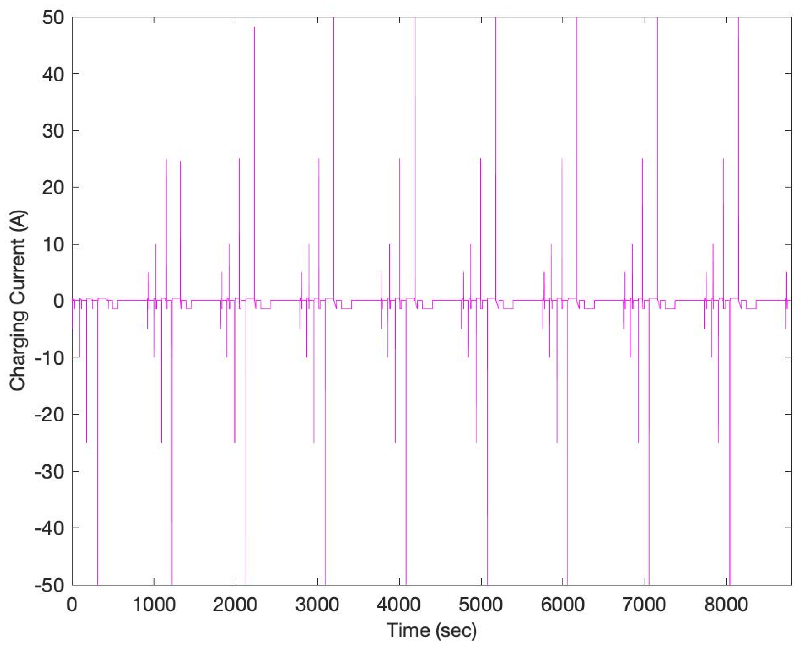
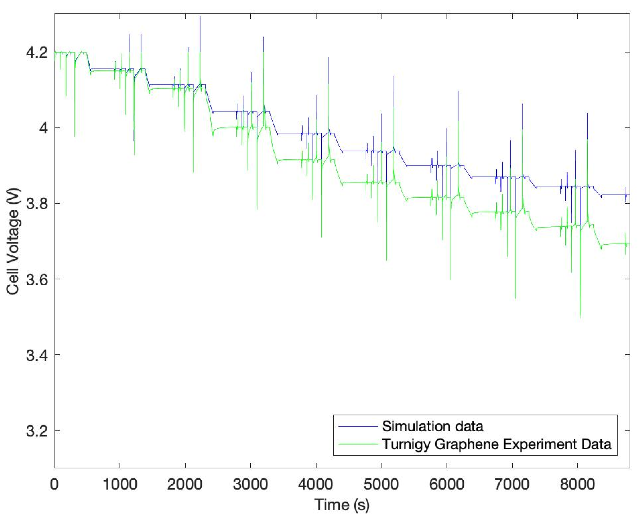
Furthermore, we applied the proposed model to the experimental publicly available dataset for a Turnigy graphene 5000 mAh 65C lithium-ion battery [52]. This dataset includes different charging and discharging currents between −50 A and 50 A, as shown in Figure 11. Figure 12. Shows the evaluation of the simulation cell voltage. The MAE value was 0.06 V, and the RMS value was 0.07 V. These error values were close to the 18,650 battery values.

4. Conclusions

In this manuscript, a novel effort was introduced to develop a battery analysis model that enables designers to generate significant battery parameters for a specific load, such as the cell voltage, battery impedance, open-circuit voltage, and temperature, during the charging/discharging cycles. The proposed model used a simulated open-circuit voltage and changes in entropy data instead of experimental data to provide battery voltage and temperature profiles during charging and discharging cycles in the development of the final model. This simulated data reduced the time and effort required to conduct many experimental tests of the open-circuit voltage and entropy for the 18,650 battery. This model is essential because it helps build a reversible battery model that could be used to develop a better battery charging algorithm, especially for the artificial intelligence charging techniques that will be used in the near future. The model simulation data and the NASA experimental data were compared. The MAE for the simulated charging cell voltage and the temperature values were 0.05 V and 0.3 °C compared with 0.14 V and 0.65 °C for the discharging profile. In addition, the RMS for the simulated charging cell voltage and the temperature values were 0.06 V and 0.38 °C compared with 0.2 V and 0.89 °C for the discharging profile. Our future effort will focus on decreasing the model errors during the relaxation time.

Author Contributions

A.A.-R. is the first author participated in conceptualization, investigation, methodology, validation, project administration, writing the manuscript, and providing the resources. A.A. and Z.M.D. participated in writing the manuscript, validation, and reviewing and editing the manuscript. A.A.-R. and A.A. participated on funding acquisition. All authors have read and agreed to the published version of the manuscript.

Funding

This work was partially funded by the King Abdullah I School of Graduate Studies and Scientific Research at the Princess Sumaya University for Technology.

Institutional Review Board Statement

Not applicable.

Informed Consent Statement

Not applicable.

Data Availability Statement

Not applicable.

Conflicts of Interest

The authors declare no conflict of interest.

References

  1. Yoshino, A. The Birth of the Lithium-Ion Battery. Angew. Chem. Int. Ed. 2012, 51, 5798–5800. [Google Scholar] [CrossRef] [PubMed]
  2. Hu, B.; Ma, Z.; Lei, W.; Zou, Y.; Lu, C. A chemo-mechanical model coupled with thermal effect on the hollow core–shell electrodes in lithium-ion batteries. Theor. Appl. Mech. Lett. 2017, 7, 199–206. [Google Scholar] [CrossRef]
  3. Dees, D.W.; Battaglia, V.S.; Bélanger, A. Electrochemical modeling of lithium polymer batteries. J. Power Sources 2002, 110, 310–320. [Google Scholar] [CrossRef]
  4. Song, L.; Evans, J.W. Electrochemical-Thermal Model of Lithium Polymer Batteries. J. Electrochem. Soc. 2000, 147, 2086–2095. [Google Scholar] [CrossRef]
  5. Yang, Z.; Patil, D.; Fahimi, B. Electrothermal Modeling of Lithium-Ion Batteries for Electric Vehicles. IEEE Trans. Veh. Technol. 2018, 68, 170–179. [Google Scholar] [CrossRef]
  6. Gomadam, P.M.; Weidner, J.W.; Dougal, R.A.; White, R.E. Mathematical modeling of lithium-ion and nickel battery systems. J. Power Sources 2002, 110, 267–284. [Google Scholar] [CrossRef]
  7. Newman, J.; Thomas, K.E.; Hafezi, H.; Wheeler, D.R. Modeling of lithium-ion batteries. J. Power Sources 2003, 119–121, 838–843. [Google Scholar] [CrossRef]
  8. Chen, M.; Rincon-Mora, G.A. Accurate electrical battery model capable of predicting runtime and IV perfor-mance. IEEE Trans. Energy Convers. 2006, 21, 504–511. [Google Scholar] [CrossRef]
  9. Rakhmatov, D.; Vrudhula, S.; Wallach, D. A model for battery lifetime analysis for organizing applications on a pocket computer. IEEE Trans. Very Large Scale Integr. (VLSI) Syst. 2003, 11, 1019–1030. [Google Scholar] [CrossRef]
  10. Rong, P.; Pedram, M. An analytical model for predicting the remaining battery capacity of lithium-ion batteries. IEEE Trans. Very Large Scale Integr. (VLSI) Syst. 2006, 14, 441–451. [Google Scholar] [CrossRef]
  11. Sun, F.; Yi, C.; Li, Y. Battery-friendly scheduling policy in MAC layer for WBAN data packets transmission. IET Commun. 2017, 11, 1423–1430. [Google Scholar] [CrossRef]
  12. Pedram, M.; Wu, Q. Design considerations for battery-powered electronics. In Proceedings of the 1999 Design Automation Conference (Cat. No. 99CH36361), New Orleans, LA, USA, 21–25 June 1999; pp. 861–866. [Google Scholar] [CrossRef]
  13. Rynkiewicz, R. Discharge and charge modeling of lead acid batteries. In Proceedings of the APEC ’99. Fourteenth Annual Applied Power Electronics Conference and Exposition. 1999 Conference Proceedings (Cat. No.99CH36285), Dallas, TX, USA, 19–23 March 1999; Volume 2, pp. 707–710. [Google Scholar] [CrossRef]
  14. Chiasserini, C.-F.; Rao, R. Energy efficient battery management. IEEE J. Sel. Areas Commun. 2001, 19, 1235–1245. [Google Scholar] [CrossRef]
  15. Pascoe, P.; Al-Anbuky, A. VRLA Battery Discharge Reserve Time Estimation. IEEE Trans. Power Electron. 2004, 19, 1515–1522. [Google Scholar] [CrossRef]
  16. Zhou, F.; Bao, C. Analysis of the lithium-ion battery capacity degradation behavior with a comprehensive math-ematical model. J. Power Sources 2021, 515, 230630. [Google Scholar] [CrossRef]
  17. Wang, C.-J.; Zhu, Y.-L.; Fan, X.-K.; Qi, C.; Gao, F. Mathematical model for thermal behavior of lithium-ion battery pack under overheating. Appl. Therm. Eng. 2021, 191, 116894. [Google Scholar] [CrossRef]
  18. Chan, H. A new battery model for use with battery energy storage systems and electric vehicles power systems. In Proceedings of the 2000 IEEE Power Engineering Society Winter Meeting. Conference Proceedings (Cat. No.00CH37077), Singapore, 23–27 January 2000; Volume 1, pp. 470–475. [Google Scholar] [CrossRef]
  19. Zhan, C.-J.; Wu, X.; Kromlidis, S.; Ramachandaramurthy, V.; Barnes, M.; Jenkins, N.; Ruddell, A. Two electrical models of the lead–acid battery used in a dynamic voltage restorer. IEE Proc.-Gener. Transm. Distrib. 2003, 150, 175–182. [Google Scholar] [CrossRef]
  20. Salameh, Z.; Casacca, M.; Lynch, W. A mathematical model for lead-acid batteries. IEEE Trans. Energy Convers. 1992, 7, 93–98. [Google Scholar] [CrossRef]
  21. Gold, S. A PSPICE macromodel for lithium-ion batteries. In Proceedings of the Twelfth Annual Battery Conference on Applications and Advances, California, CA, USA, 14–17 January 1997; pp. 215–222. [Google Scholar] [CrossRef]
  22. Glass, M. Battery electrochemical nonlinear/dynamic SPICE model. In Proceedings of the IECEC 96. Proceedings of the 31st Intersociety Energy Conversion Engineering Conference, Washington, DC, USA, 11–16 August 1996; Volume 1, pp. 292–297. [Google Scholar] [CrossRef]
  23. Valvo, M.; Wicks, F.; Robertson, D.; Rudin, S. Development and application of an improved equivalent circuit model of a lead acid battery. In Proceedings of the IECEC 96. Proceedings of the 31st Intersociety Energy Conversion Engineering Conference, Washington, DC, USA, 11–16 August 1996; Volume 2, pp. 1159–1163. [Google Scholar] [CrossRef]
  24. Kim, D.; Lee, J. Discharge scheduling for voltage balancing in reconfigurable battery systems. Electron. Lett. 2017, 53, 496–498. [Google Scholar] [CrossRef]
  25. Benini, L.; Castelli, G.; Macii, A.; Macii, E.; Poncino, M.; Scarsi, R. Discrete-time battery models for system-level low-power design. IEEE Trans. Very Large Scale Integr. (VLSI) Syst. 2001, 9, 630–640. [Google Scholar] [CrossRef]
  26. Gao, L.; Liu, S.; Dougal, R. Dynamic lithium-ion battery model for system simulation. IEEE Trans. Components Packag. Technol. 2002, 25, 495–505. [Google Scholar] [CrossRef] [Green Version]
  27. Barsali, S.; Ceraolo, M. Dynamical models of lead-acid batteries: Implementation issues. IEEE Trans. Energy Convers. 2002, 17, 16–23. [Google Scholar] [CrossRef]
  28. Baudry, P.; Neri, M.; Gueguen, M.; Lonchampt, G. Electro-thermal modelling of polymer lithium batteries for starting period and pulse power. J. Power Sources 1995, 54, 393–396. [Google Scholar] [CrossRef]
  29. Huang, C.; Wang, L. Gaussian process regression-based modelling of lithium-ion battery temperature-dependent open-circuit-voltage. Electron. Lett. 2017, 53, 1214–1216. [Google Scholar] [CrossRef] [Green Version]
  30. Buller, S.; Thele, M.; De Doncker, R.W.; Karden, E. Impedance based simulation models of supercapacitors and Li-ion batteries for power electronic applications. IEEE Trans. Ind. Appl. 2005, 41, 742–747. [Google Scholar] [CrossRef]
  31. Schweighofer, B.; Raab, K.; Brasseur, G. Modeling of high power automotive batteries by the use of an automated test system. IEEE Trans. Instrum. Meas. 2003, 52, 1087–1091. [Google Scholar] [CrossRef]
  32. Ceraolo, M. New dynamical models of lead-acid batteries. IEEE Trans. Power Syst. 2000, 15, 1184–1190. [Google Scholar] [CrossRef] [Green Version]
  33. Abu-Sharkh, S.; Doerffel, D. Rapid test and non-linear model characterisation of solid-state lithium-ion batteries. J. Power Sources 2004, 130, 266–274. [Google Scholar] [CrossRef]
  34. Khalfi, J.; Boumaaz, N.; Soulmani, A.; Laadissi, E.M. Nonlinear Modeling of Lithium-Ion Battery Cells for Electric Vehicles using a Hammerstein–Wiener Model. J. Electr. Eng. Technol. 2020, 16, 659–669. [Google Scholar] [CrossRef]
  35. Tran, M.K.; Panchal, S.; Chauhan, V.; Brahmbhatt, N.; Mevawalla, A.; Fraser, R.; Fowler, M. Python-based scikit-learn machine learning models for thermal and electrical performance prediction of high-capacity lithium-ion battery. Int. J. Energy Res. 2022, 46, 786–794. [Google Scholar] [CrossRef]
  36. Lacressonnière, F.; Varais, A.; Roboam, X.; Bru, E.; Mullins, T. Scale electro-thermal model of a lithium-ion battery for time-accelerated experiments in a hardware in the loop process. J. Energy Storage 2021, 39, 102576. [Google Scholar] [CrossRef]
  37. Chen, L.; Hu, M.; Cao, K.; Li, S.; Su, Z.; Jin, G.; Fu, C. Core temperature estimation based on electro-thermal model of lithium-ion batteries. Int. J. Energy Res. 2020, 44, 5320–5333. [Google Scholar] [CrossRef]
  38. Kuntinugunetanon, S.; Meesiri, W.; Wongkokua, W. Internal resistance measurements of Li-ion batteries using AC methods. J. Physics Conf. Ser. 2021, 1719, 012045. [Google Scholar] [CrossRef]
  39. Erdinc, O.; Vural, B.; Uzunoglu, M. A dynamic lithium-ion battery model considering the effects of temperature and capacity fading. In Proceedings of the 2009 International Conference on Clean Electrical Power, Capri, Italy, 9–11 June 2009; pp. 383, 386. [Google Scholar] [CrossRef]
  40. He, H.; Xiong, R.; Zhang, X.; Sun, F.; Fan, J. State-of-Charge Estimation of the Lithium-Ion Battery Using an Adaptive Extended Kalman Filter Based on an Improved Thevenin Model. IEEE Trans. Veh. Technol. 2011, 60, 1461–1469. [Google Scholar] [CrossRef]
  41. Crompton, T.R. Battery Reference Book, 3rd ed.; Newnes: Oxford, UK, 2000. [Google Scholar]
  42. Charkhgard, M.; Farrokhi, M. State-of-Charge Estimation for Lithium-Ion Batteries Using Neural Networks and EKF. IEEE Trans. Ind. Electron. 2010, 57, 4178–4187. [Google Scholar] [CrossRef]
  43. Plett, G.L. Extended Kalman filtering for battery management systems of LiPB-based HEV battery packs, Part 2: Modeling and identification. J. Power Sources 2004, 134, 262–276. [Google Scholar] [CrossRef]
  44. Wang, S.; Fan, Y.; Stroe, D.; Fernandez, C.; Yu, C.; Cao, W.; Chen, Z. Chapter 5—Battery state-of-charge estimation methods. In Battery System Modeling; Elsevier: Amsterdam, The Netherlands, 2021; pp. 157–198. [Google Scholar]
  45. Choi, W.; Shin, H.-C.; Kim, J.M.; Choi, J.-Y.; Yoon, W.-S. Modeling and Applications of Electrochemical Impedance Spectroscopy (EIS) for Lithium-ion Batteries. J. Electrochem. Sci. Technol. 2020, 11, 528. [Google Scholar] [CrossRef] [Green Version]
  46. Schweitzer, B.; Wilke, S.; Khateeb, S.; Al-Hallaj, S. Experimental validation of a 0-D numerical model for phase change thermal management systems in lithium-ion batteries. J. Power Sources 2015, 287, 211–219. [Google Scholar] [CrossRef]
  47. Al Hallaj, S.; Prakash, J.; Selman, J. Characterization of commercial Li-ion batteries using electrochemical–calorimetric measurements. J. Power Sources 2000, 87, 186–194. [Google Scholar] [CrossRef]
  48. Mills, A.; Al-Hallaj, S. Simulation of passive thermal management system for lithium-ion battery packs. J. Power Sources 2005, 141, 307–315. [Google Scholar] [CrossRef]
  49. Al-Hallaj, S.; Selman, J. Thermal modeling of secondary lithium batteries for electric vehicle/hybrid electric vehicle applications. J. Power Sources 2002, 110, 341–348. [Google Scholar] [CrossRef]
  50. Viswanathan, V.V.; Choi, D.; Wang, D.; Xu, W.; Towne, S.; Williford, R.E.; Zhang, J.-G.; Liu, J.; Yang, Z. Effect of entropy change of lithium intercalation in cathodes and anodes on Li-ion battery thermal management. J. Power Sources 2010, 195, 3720–3729. [Google Scholar] [CrossRef]
  51. Saha, B.; Goebel, K. Battery Data Set; NASA Ames Prognostics Data Repository, Ames Research Center: Moffett Field, CA, USA, 2007. Available online: http://ti.arc.nasa.gov/project/prognostic-data-repository (accessed on 2 October 2022).
  52. Kollmeyer, P.; Skells, M. Turnigy Graphene 5000 mAh 65C Li-ion Battery Data. Mendeley Data 2020, 1. [Google Scholar] [CrossRef]
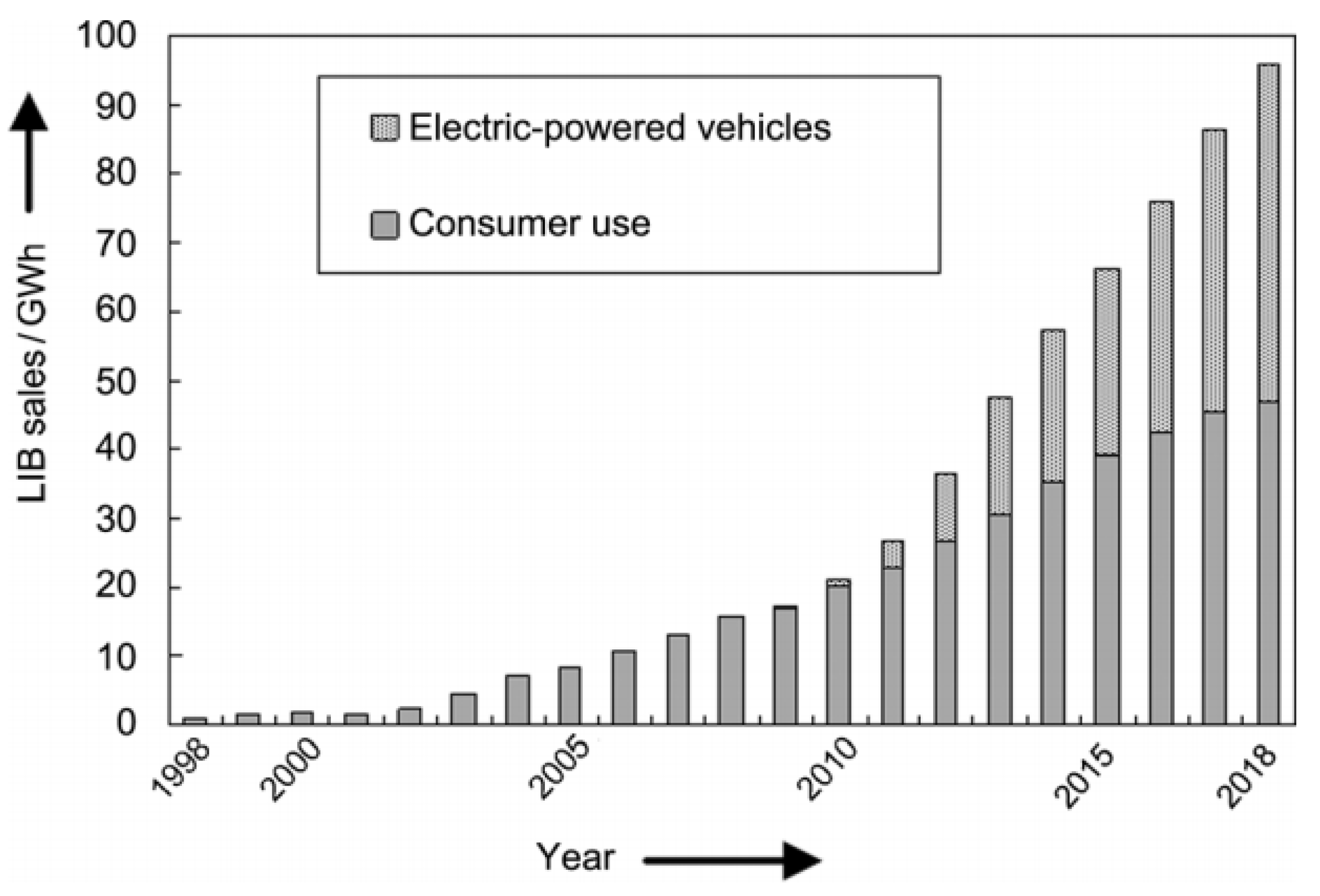
Figure 1. Anticipated growth in the need for lithium-ion batteries. GWh: gigawatt hours. Reprinted with permission from Ref. [1]. 2022, Angewandte Chemie International Edition.
Batteries 08 00199 g001
Figure 2. Chen and Mora’s electrical battery model.
Batteries 08 00199 g002
Figure 3. A workflow view of the proposed electrical temperature model.
Batteries 08 00199 g003
Figure 4. The experimental charging/discharging profiles of the B0005 battery dataset over time.
Batteries 08 00199 g004
Figure 5. The change in the simulated battery open-circuit voltage over time for the charging/discharging profiles.
Batteries 08 00199 g005
Figure 6. The change in the simulated internal battery impedance over time for the charging/discharging cycles.
Batteries 08 00199 g006
Figure 7. The cell voltage over time for the CC-CV phases for the proposed and the experimental models for the charging/discharging cycles.
Batteries 08 00199 g007
Figure 8. The simulated irreversible ohmic heating during charging/discharging cycles.
Batteries 08 00199 g008
Figure 9. The simulated reversible entropic heating during charging/discharging cycles.
Batteries 08 00199 g009
Figure 10. The charging battery temperature profiles of the proposed and the experimental models for the charging/discharging cycles.
Batteries 08 00199 g010
Figure 11. The experimental charging/discharging profiles for the Turnigy graphene battery dataset over time.
Batteries 08 00199 g011
Figure 12. The cell voltage for the proposed model and the experimental Turnigy graphene battery dataset over time.
Batteries 08 00199 g012
Table 1. Battery parameters.
ParametersValueUnit
Nominal Capacity2000mAh
Charging Voltage4.2V
Nominal Voltage3.7V
Battery Weight45G
Battery Diameter18.2Mm
Battery Height64.5Mm
H16W/(m2 × K)
Cp850kJ/(kg × k)
Table 2. Statistics list of the fitted error of the charging and discharging profiles.
ProfileMAERMS
Charging Cell Voltage0.05 V0.06 V
Charging Battery Temperature0.3 °C0.38 °C
Discharging Cell Voltage0.14 V0.2 V
Discharging Battery Temperature0.65 °C0.89 °C
Publisher’s Note: MDPI stays neutral with regard to jurisdictional claims in published maps and institutional affiliations.