Article

Fabrication of a Flexible Current Collector for Lithium Ion Batteries by Inkjet Printing

Flexible Electronic Devices and Sensors Lab, Department of Physics, New Jersey Institute of Technology, Newark, NJ 07102, USA
*
Author to whom correspondence should be addressed.
Batteries 2018, 4(3), 42; https://doi.org/10.3390/batteries4030042
Submission received: 5 July 2018 / Revised: 4 August 2018 / Accepted: 7 August 2018 / Published: 3 September 2018

Abstract

:
A novel chemical process has been developed to formulate injectable nickel ink for conductive film. This chemical method has the ability to remove the oxidation on nickel nano-particle surfaces during ink fabrication; the nickel ions, which are produced during chemical etching, will be reduced and bridged among original nano-nickel particles in the following thermal sintering process at 350 °C. X-ray diffraction results exhibit that the final nickel film has no significant composition change by this chemical method and that oxidation has been effectively removed. Scanning electron microscopy images show that this chemical process reduces nickel oxides into nickel and that the reduced nickel sticks on the original nickel particle surface acting as a “bridge” connecting each particle. So solid diffusion can be triggered easily among bridged nickel particles and sintered at relatively low temperatures. The resistivity of printed film is to 5 × 10 6   Ω ∙m which is 71-times that of bulk nickel. The fabricated conductive nickel thin film has been applied on lithium ion batteries as a current collector for cathode and anode and shows good corrosion resistance and stability.

1. Introduction

In recent years, there has been growing attention given to the fabrication of energy storage devices like supercapacitors and solar cells with the development of electronics. Among chemical energy storage devices, lithium ion batteries have outstanding performance such as: high energy density, high capacity, easy fabrication process and high working voltage. In the last decades, lithium ion batteries have been among of the most widely used portable energy sources. A lithium ion battery is composed of cathode and anode current collectors, cathode and anode active materials, separator and electrolyte. The current collector is used to provide conduction of electrons from inside the electrochemical reaction to the external part without any reaction within the operation window. The commercially available current collectors for cathode and anode are aluminum and copper, respectively. Aluminum is usually covered with a dense passive oxidation layer which can prevent aluminum from further oxidation. Moreover, this passivation has very minor effects on the conductivity of aluminum. Aluminum cannot be used as an anode current collector because it reacts with lithium ions at low potential to form an aluminum–lithium alloy and eventually cause battery failure. Copper is the most commonly used anode current collector for lithium ion batteries due to its good stability at low potential. The active materials are mixed with conductive agents (usually carbon materials) and binder and then covered on the current collectors by tape casting. The fabricated cathode and anode electrodes are then soaked in electrolyte and isolated from each other by the separator, and then the battery is assembled in an oxygen and water-free glove box. It is very difficult to customize the arbitrary shape and flexibility of lithium ion batteries by a traditional tape casting procedure. Therefore, it is desirable to develop a more customizable method to fabricate lithium ion batteries.
There are many approaches to make thin and flexible circuitry on conformal surfaces such as transfer printing [1,2] and direct-write printing [3,4]. Among those manufacturing methods, inkjet printing is one of the most promising manufactory methods to make thin films due to its digital direct-writing approach without any need for physical masks to enable patterning. More and more researchers have reported inkjet-printed energy storage devices [5,6,7,8,9]. However, only few have focused on printing lithium ion batteries. Printing current collectors is the main barrier preventing a fully printed lithium ion battery. Take aluminum for instance; the commercially available aluminum ink has to be annealed at temperatures above 600 °C in forming gas to make it conductive. However, to the best of our knowledge, no plastic substrate could survive at such a high temperature. There are also reports using precursor aluminum inks such as alane (AlH3) to make flexible aluminum cathode [10], but alane is too reactive to print at a normal environment. The most reported material for lithium ion battery cathode and anode current collectors is gold [11], because it has fascinating chemical stability and excellent corrosion resistance. Gold is also printed as an anode current collector to replace copper current collector because of its outstanding physical and chemical properties. Another reason for using gold ink to make anode current collectors is reducing the complexity of printing caused by ink changes. Gold ink has been developed to study the possibility and performances of prototype printable batteries. However, gold current collector has very limited industrial production because of its low performance and economic cost ratio. Carbon material also has good corrosion resistance inside the battery. However, it is restricted by its high contact resistance. The other problem regarding carbon materials is the poor adhesion on the polymer substrate which leads into active material peeling off from the electrodes and causes battery failure.
Among metallic materials, nickel is an excellent material for batteries due to its high electrochemical stability; it is protected by the passivated layer which prevents nickel reacting with lithium ions and further oxidation makes it very stable under a certain voltage inside the battery [12]. James H. Pikul reported a method to fabricate micro lithium ion batteries with nickel scaffolds in both cathode and anode current collectors [13]. The issue with nickel material is that the passivation layer prevents nickel from thermal sintering at low temperatures and the fabricated nickel films have very high resistivity due to poor sintering. Dapeng Li fabricated a nickel conductive film on a flexible substrate by nickel precursor ink [14] as illustrated in Figure 1. Nickel precursor ink is deposited on substrate first (Figure 1a); a reducing agent is then deposited on the nickel precursor to make nickel metals (Figure 1b); finally, the reduced nickel has high surface energy and tends to merge together to form the nickel film on the substrate (Figure 1c).
This nickel precursor multi-printing method removes the surface oxidation from nickel nanoparticles and makes the printed nickel film conductive. However, the drawback of this printing procedure is that it is hard to control the reducing agents to nickel precursor ratio and produces chemical remains which lower the conductivity of the fabricated nickel film.
As discussed above, the difficulty of making nickel nanoparticle-based ink is breaking through the passivation oxidation layer as shown in Figure 2a–c. The passivation layer prevents sintering and increases the resistance of the printed film. In this paper, a novel and simple chemical reactive nickel ink is formulated for inkjet printing conductive nickel film at flexible polymer substrate. Figure 2 shows the schematics of this chemical reactive sintering (CRS) process: (a) nickel powders are dispersed in DI water; (d) etching agents (NH4Cl in this case) are added into the suspension to etch away oxidation layers on nickel nanoparticles and form a nickel ammonia complex dissolved in the ink; (e) after chemical etching, a mild reductant thiourea dioxide (TD) and additional Ni2+ are added to the suspension. It should be noted that Ni2+ cannot be reduced by thiourea dioxide (TD) at room temperature; (f) the ink is deposited by inkjet printing and sintered in a vacuum furnace: in this process the reductant can reduce etched nickel ions into nickel nanoparticles which stick on the existing nickel particles like “metallic bridge” to connect the original nickel particles and trigger the solid diffusion during the sintering. No forming gas is needed in this step; (g) the passivation layer is reformed on the sintered nickel film in air and acts as a protection layer.

2. Experiment

2.1. Materials

Commercially available nickel (US Research Nanomaterials Inc., Houston, TX, USA) nano powders are used to make conductive ink. Polyvinylpyrrolidone (PVP), ammonia chloride (NH4Cl), nickel chloride hexahydrate (NiCl2∙6H2O) and thiourea dioxide (TD) (Sigma Aldrich, St. Louis, MO, USA) are used as the capping agent, etching agent, nickel additive and reductant, respectively. Potassium hydroxide (Sigma Aldrich, USA) is used to adjust the ink’s pH value. The viscosity is adjusted by glycerol (Sigma Aldrich, USA) to meet the requirements of inkjet printers. LiNi1/3Co1/3Mn1/3O2 (NMC), Li4Ti5O12 (LTO), carbon black and Triton X-100 (Sigma Aldrich, USA) are used as battery active materials, conductive agent, and surfactant to fabricate battery inks.

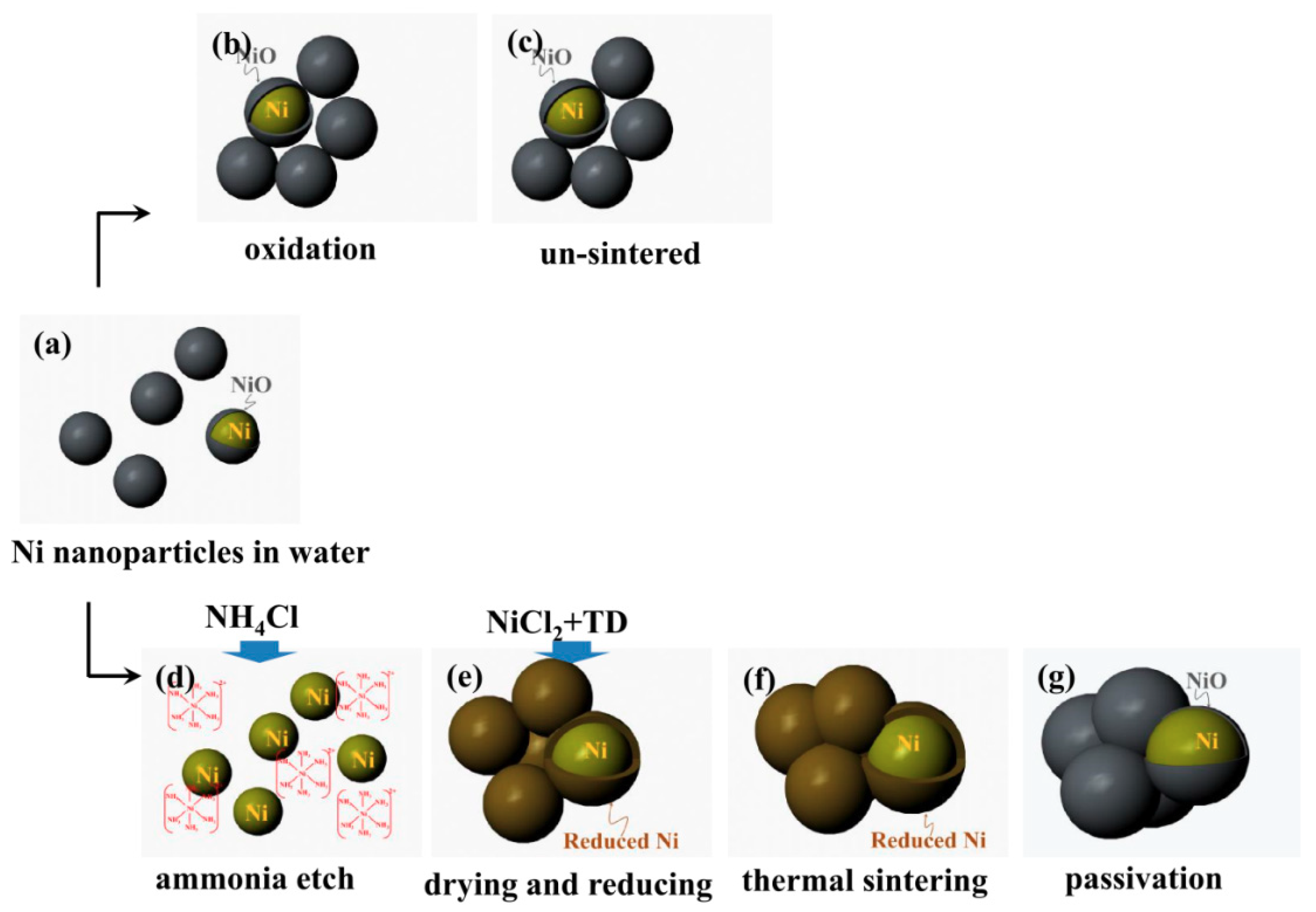
2.2. Synthesis of Nickel Nanoparticle and Battery Inks

Nickel particles, PVP and DI water are mixed with the weight ratio: 7:1:13. The mixture is mixed overnight. NH4Cl is added into the suspension by weight ratio: NH4Cl: nickel powder = 0.1:1. The mixture is probe ultrasonicated for 30 min to dissolve etching agent and disperse the nanoparticles in the suspension and to break agglomerates. The suspension is then centrifuged at 2000 rpm to separate big particles. NiCl2∙6H2O is added into the dispersion by 5 wt.% of nickel powder to add more Ni2+. Thiourea dioxide (0.3 mol/L) is then added to the suspension and mechanical stirred for 30 min. pH value was adjusted to 13 by potassium hydroxide; the formulated ink is obtained after another 30 min of stirring. In this recipe, the viscosity and surface tension are adjusted to 10 cp and 55 dyne/cm by glycerol to establish a good jetability.
The nickel oxidation is etched by NH4Cl solution to form metal ammonia complex by the following reaction:
Ni 2 + + 6 NH 3 = [ Ni ( NH 3 ) 6 ] 2 +
The etched nickel in the form of nickel ammonia complexions would be reduced very easily by high chemical active SO22− released from TD in basic environment at a certain temperature [15]:
( NH 2 ) 2 CSO 2 + 2 KOH = ( NH 2 ) 2 CO + K 2 SO 2 + H 2 O
K 2 SO 2 + [ Ni ( NH 3 ) 6 ] 2 + + 2 OH Ni + H 2 O + K 2 SO 3 + 6 NH 3
In this research, commercially available LTO and NMC nano-powders are used as active materials for lithium batteries. The battery inks (cathode and anode inks) contains: water, Triton X-100 and battery materials. The weight ratio of Triton X-100 to solid is fixed at 1:9. The battery materials contain 80 wt % wt. active material (NMC for cathode and LTO for anode), 10 wt % carbon black as conductive agent and 10 wt %. PVP is used as binder and polymer surfactant. The mixed suspensions are first mixed by a rotating mixer overnight and then probe ultra-sonicated for 30 min, and then centrifuged at 2000 rpm to eliminate large particles.

2.3. Fabrication of Cathode and Anode for Battery

Conductive nickel current collectors are prepared from the nickel nano particle inks by inkjet printer (DMX-2800, Fujifilm, Santa Clara, CA, USA) on Kapton substrate (Dupont, Wilmington, DE, USA). The firing voltage was set at 25 V. The maximum jetting frequency was set at 5 KHz. Both cathode and anode current collectors are printed 10 layers.
The printed current collectors are first dried in vacuum at 100 °C overnight. The dried current collectors are then transferred to a vacuum furnace and sintered at 350 °C for 1 h and then cooled down to room temperature.
The formulated cathode and anode inks are inkjet printed on the nickel conductive film (10 layers) and dried in vacuum at 100 °C for 12 h to evaporate the solvent. The batteries are assembled in Argon protective glovebox. The battery structure is demonstrated in Figure 3: nickel current collector is inkjet printed on Kapton substrate (Figure 3a); cathode and anode materials are inkjet printed on the nickel current collectors (Figure 3b); cathode and anode are folded together, and glue sealed (Figure 3c). LiPF6 (1 M) in a 1:1 (v/v) mixture of dimethyl carbonate (DMC) and ethylene carbonate (EC) is used as electrolyte. The separator is Celgard2400.

2.4. Characterization

X-ray diffraction (XRD) measurements were carried out on a Philips PW3040 X-Ray Diffractometer, 2θ ranges from 10° to 90° with Cu Kα radiation (λ = 15.4 nm) with a step size of 0.02° and a time per step of 15 s. LEO 1530VP Field Emission Scanning electron microscope (SEM) was used to examine surface morphology of electrodes. Punch cells were cycled at a rate of 0.1 C (1 C = 150 mAh g−1) between 0.5 and 2.5 V at 25 °C, using a Battery Analyzer (BST8-MA, MTI Inc., Richmond, CA, USA). The cyclic voltammetry (CV) measurements were carried out on CHI832C (CH Instruments, Inc., Austin, TX, USA) at 25 °C. Thermogravimetric analysis (TGA) and Differential thermal analysis (DTA), STA 449 F1 Jupiter from Netzsch, Inc., Burlington, MA, USA, are used to study the thermal behavior of different constantan inks and chemical reaction processes. Thermal analysis is carried out in nitrogen with temperature rise 5 K/min.

3. Results and Discussion

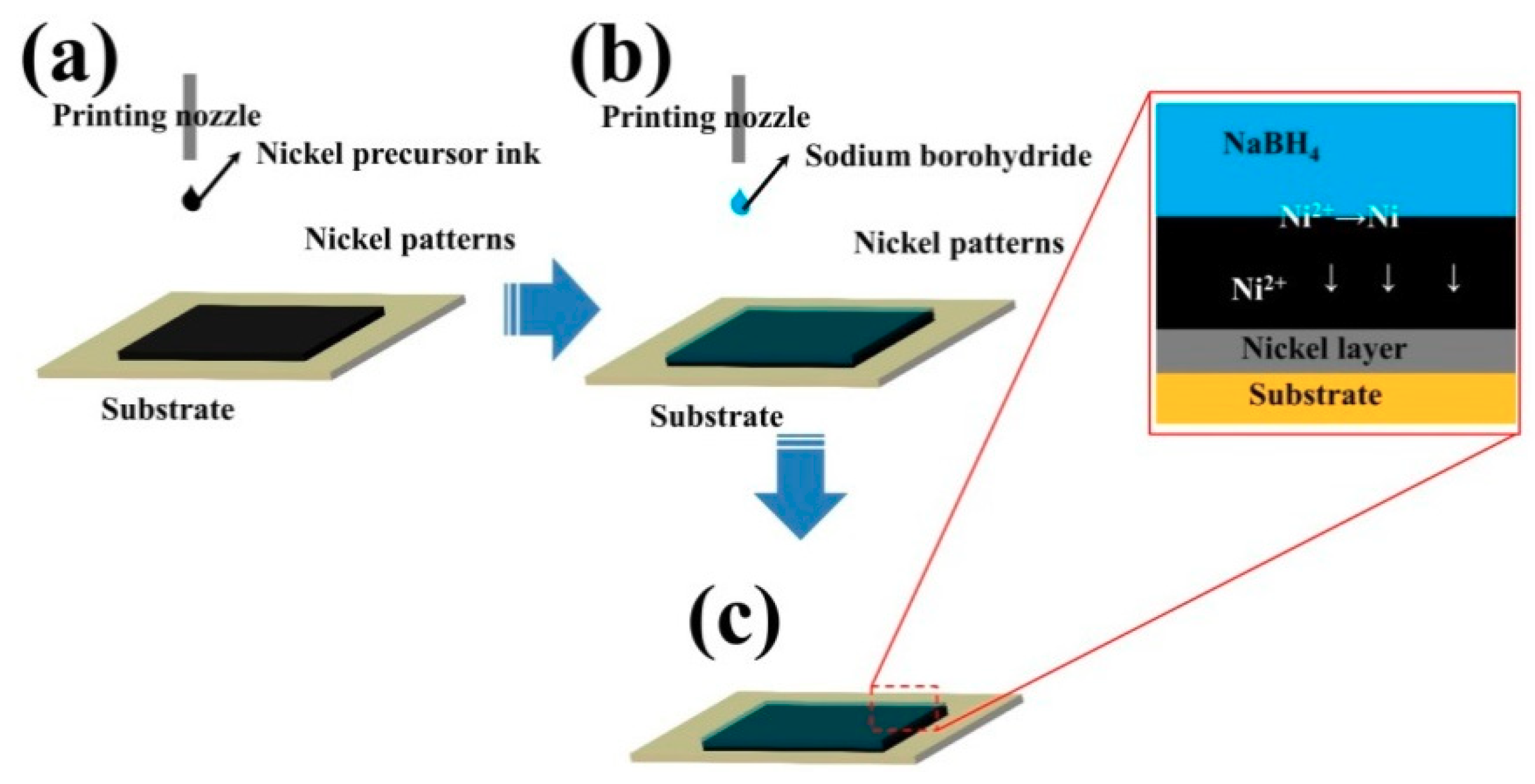
3.1. Nickel Current Collectors for Flexible Batteries

Figure 4a presents the droplets jetting out from a 10 pL nozzle which shows a good printability of the formulated ink. No nozzle clogging or satellite spots were detected form the drop watcher. The stability of the ink was also evaluated by aging the synthesized ink for different times (1 day, 2 days, a week, two weeks and a month) at 4 °C. Here, the nickel suspension (Nickel particles, PVP and DI) was aged without adding NiCl2∙6H2O, NH4Cl, TD and KOH. We only mixed all those chemicals right before printing. The synthesized nickel suspension is very stable over a long time without particle settling down.
Thermogravimetric analysis (TGA) and Differential thermal analysis (DTA) are carried out to study the chemical process of nickel ink in Figure 5a. “exo” is abbreviation exothermic reaction. DTA curve has 3 main endothermic peaks: (a) endothermic peak before 100 °C is due to the nickel reduction, no obvious mass loss in this stage from TGA; (b) endothermic peak between 150–200 °C is due to the solvent evaporation which is 20 wt % in TGA; (c) endothermic peak between 200–250 °C is due to the evaporation of glycerol which is 35 wt % as well. The final solid loading of this ink is 35% from the TGA. Figure 5b shows the XRD patterns of nickel nano-powders before and after thermal sintering. All of the peaks at 2θ of 44.5°, 51.8° and 76.4° could be indexed as (111), (200) and (220) (JCPDS file No. 04-0783) with Fm-3m space group. No obvious significant impurities are detected from XRD results. Usually, nickel nano-powders are covered by a thin and dense passivation oxidation layer in air. However, this passivation is too thin to be detected by XRD. This phenomenon is similar as aluminum, which is covered by oxidation to prevent metal being furtherly corroded. The passivation is chemically inactive and has high melting temperatures, which behaves as a barrier during thermal sintering and prevent solid diffusion among nickel nanoparticles. After CRS process, no impurities remain detected in the nickel patterns, which suggests most of extra chloride and ammonia are evaporated during the thermal sintering. Compared with the nickel precursor multi-printing method mentioned above [14], the amount of reductants and reaction by-products have been minimized in CRS process.
Figure 6 shows the surface morphology of nickel powders before and after the CRS process. The original particle size of the sphered nickel particles is below 100 nm (Figure 6a,b). Primary particles aggregate together and form micro-sized bundles to reduce the surface energy. These aggregated particles must be separated in order to reduce the risk of nozzle clogging. In this ink formulation, water soluble PVP is used as a surfactant to separate nickel nanoparticles with the help of ultra-sonication. After CRS processing, the particles are joined together very well. The surface becomes much smoother. Neck formation, marked with black arrows, is found among particles which indicate grain growth happens during sintering as shown in Figure 6c. The reduced nickel nucleates and grows on the original nickel particles (etched without oxidation), which acts like bridge to enhance the solid diffusion under certain temperature. However, due to the high melting temperature of nickel, the nickel nanoparticles are not fully sintered as seen from those individual nickel particle remains from the SEM. The thickness of printed nickel current collectors is around 10 μm from the cross-section view in Figure 6d. Micro cracks are also detected from the cross section of the nickel film which is caused by the low solid loading; this micro crack structure increases the resistivity of nickel current collectors.
Figure 7 displays the resistance of the printed patterns. The thickness of fabricated film is around 10 μm as seen from SEM. The insert photo is the sintered nickel patterns printed on kapton film, which shows good mechanical flexibility; this suggests CRS can make conductive nickel patterns without damaging the kapton substrate. The resistivity of the printed nickel pattern is measured by a four-probe meter which is 5 × 10 6 Ω∙m which is 71 times higher than bulk nickel. This measured resistivity is ten times lower than the nickel precursor multi-printing method reported [14] because of the better sintering process and less chemical reaction by-products.

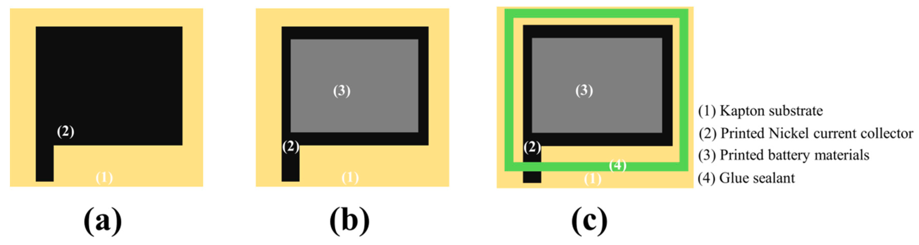
3.2. Flexible Battery with Nickel Current Collector

The printed nickel ink has potential application in the lithium ion batteries in current collectors due to the chemical stability and corrosion resistance. The resistivity of thin films made by different materials is summarized on Table 1 including the nickel film in this research, all these materials have potential application on the battery current collector (aluminum is not included). From Table 1, gold [11] (other noble metals like platinum is also good current collector for lithium ion batteries, but not show in this research) is obvious the most outstanding material for the fabrication of printable batteries. However, gold is expensive which limits the application on the printable batteries. Carbon is an ideal material for the batteries [16,17] which has been applied on the battery as conductive agent, but carbon suffers high resistance as current collector due to the carbon-carbon contact resistance. High battery internal resistance may affect the energy output of batteries caused by thermal runaway. Indium Tin Oxide (ITO) is a new conductive material which already shows excellent stability and conductivity in solar cell [18,19,20]. The application of ITO in lithium ion batteries has not been evaluated, but the market price of ITO is not as cheap as nickel nanoparticles. On the other hand, nickel film has even lower surface resistance than ITO film.
The electrochemical cyclic voltammogram (CV) technique is used to test the corrosion resistance of the printed nickel film in the electrolyte (1M LiPF6 in EC/EMC (3:7)) environment shown in Figure 8. The stainless steel is set at the same testing condition and used as the comparison because stainless steel is very stable as current collectors for lithium ion batteries. Nickel film exhibits very similar electrochemical behavior inside the electrolyte below 3.8 V as the stainless steel which is contributed by the oxidation passivation protection. A small chemical reactive signal is detected at ~3.8 V in the first cycle which represents the anode passivation process. The anodic current at a voltage of 3.8 V disappears with after the CV cycle and the anodic current becomes constant at 3.8 V, indicating that the tolerance for corrosion is improved by the irreversible anodic reaction which produces more stable passivation layers. The second and the third cycles of nickel are very close to the stainless steel. Tiefeng Liu points out Ni-P alloy [31] could be formed during the charge-discharge process which has excellent tolerance against electrolyte corrosion up to 4.5 V. Pre-phosphating treatment would furtherly increase the stability of nickel film as cathode and anode current collectors. Phosphating treatment is considered as a potential modification for the fabricated nickel current collector to furtherly increase the corrosion resistance inside the battery.
The printed nickel current collector is flexible which can be bent with 1 cm radius of curvature without any obvious peeling off or cracks as shown in Figure 9a. The sheet resistance is 0.25 Ω and 0.26 Ω before and after bending. The fabricated nickel electrodes also passed tape testing without material peeling off (done using a piece of scotch-tape which is put over the nickel current collectors, rubbing gently with a thumb and then removing the tape using a steady pulling action). After removal of the tape, the sheet resistance measurements are re-measured which is 0.25 Ω. Figure 9b demonstrates the structure of printed electrodes for lithium ion batteries. Basically, the electrodes are printed layer by layer (kapton–nickel-battery materials): battery materials (active materials and carbon conductive agent) are printed on the nickel conductive film and then assembled to a full cell. The assembled cell was clamped by an aluminum frame in order to achieve good contact between cathode and anode. So, the flexibility of assembled cell is not presented here. The assembled cell is cycled from 0~2.5 V. which indicates that the nickel film has sufficient stability as a current collector for cathode and anode in LiPF6 electrolyte during battery charge and discharge. Figure 9c shows first cycling of the fabricated flexible battery. The first charge and discharge capacity of the cell is 106 mAh/g and 96 mAh/g. The theoretical specific capacity of the NMC-LTO battery is around 160–170 mAh/g. The fabricated electrodes are not compressed as tightly as on the coin cell and result in a long distance between cathode and anode. The high internal resistance, produced by the long distance between the fabricated electrodes, leads into voltage drop and capacity loss. The cut-off voltage is set at 0.5–2.5 V and no obvious disturbance during charging and discharging curve suggests good stability of nickel current collector inside the batteries.

4. Summary and Conclusions

We invented a chemical reactive sintering (CRS) process to make nickel conductive ink. The original nickel nanoparticles are first etched by NH4Cl in aqueous suspension to remove inert oxidation; reductant (thiourea dioxide) is then added to reduce metal ions at a suitable pH value. The reduced nickel sticks on the original particles like a “bridge” or “binder” as can be seen from SEM images; the solid diffusion is triggered by the connected particles and low temperature sintering is achieved. Most of the etching agent, reductant and by-products are decomposed and removed by thermal sintering; no composition change is observed before and after the CRS process as demonstrated by XRD. The synthesized nickel current collectors have low electronical resistance and can be used as current collectors in lithium ion batteries to replace expensive noble metals (like gold and platinum) and high resistance carbon current collectors.

Author Contributions

J.F.F. and Y.G. conceived of the presented idea. Y.G. performed the experiments and data analysis.

Funding

This research received no external funding.

Acknowledgments

This work is partially supported by the US Army Armament Research, Development and Engineering Center (ARDEC) at Picatinny Arsenal.

Conflicts of Interest

The authors declare no conflict of interest.

References

  1. Le Borgne, B.; De Sagazan, O.; Crand, S.; Jacques, E.; Harnois, M. Conformal electronics wrapped around daily life objects using an original method: Water transfer printing. ACS Appl. Mater. Interfaces 2017, 9, 29424–29429. [Google Scholar] [CrossRef] [PubMed]
  2. Tao, H.; Brenckle, M.A.; Yang, M.; Zhang, J.; Liu, M.; Siebert, S.M.; Averitt, R.D.; Mannoor, M.S.; McAlpine, M.C.; Rogers, J.A. Silk-based conformal, adhesive, edible food sensors. Adv. Mater. 2012, 24, 1067–1072. [Google Scholar] [CrossRef] [PubMed]
  3. Seifert, T.; Sowade, E.; Roscher, F.; Wiemer, M.; Gessner, T.; Baumann, R.R. Additive manufacturing technologies compared: Morphology of deposits of silver ink using inkjet and aerosol jet printing. Ind. Eng. Chem. Res. 2015, 54, 769–779. [Google Scholar] [CrossRef]
  4. Rahman, T.; Renaud, L.; Heo, D.; Renn, M.; Panat, R. Aerosol based direct-write micro-additive fabrication method for sub-mm 3D metal-dielectric structures. J. Micromech. Microeng. 2015, 25, 107002. [Google Scholar] [CrossRef]
  5. Kaempgen, M.; Chan, C.K.; Ma, J.; Cui, Y.; Gruner, G. Printable thin film supercapacitors using single-walled carbon nanotubes. Nano Lett. 2009, 9, 1872–1876. [Google Scholar] [CrossRef] [PubMed]
  6. Wee, G.; Salim, T.; Lam, Y.M.; Mhaisalkar, S.G.; Srinivasan, M. Printable photo-supercapacitor using single-walled carbon nanotubes. Energy Environ. Sci. 2011, 4, 413–416. [Google Scholar] [CrossRef]
  7. Xu, Y.; Schwab, M.G.; Strudwick, A.J.; Hennig, I.; Feng, X.; Wu, Z.; Müllen, K. Screen-printable thin film supercapacitor device utilizing graphene/polyaniline inks. Adv. Energy Mater. 2013, 3, 1035–1040. [Google Scholar] [CrossRef]
  8. Mei, A.; Li, X.; Liu, L.; Ku, Z.; Liu, T.; Rong, Y.; Xu, M.; Hu, M.; Chen, J.; Yang, Y.; et al. A hole-conductor–free, fully printable mesoscopic perovskite solar cell with high stability. Science 2014, 345, 295–298. [Google Scholar] [CrossRef] [PubMed]
  9. Lee, E.; Park, S.J.; Cho, J.W.; Gwak, J.; Oh, M.-K.; Min, B.K. Nearly carbon-free printable cigs thin films for solar cell applications. Solar Energy Mater. Solar Cells 2011, 95, 2928–2932. [Google Scholar] [CrossRef]
  10. Lee, H.M.; Choi, S.Y.; Kim, K.T.; Yun, J.Y.; Jung, D.S.; Park, S.B.; Park, J. A novel solution-stamping process for preparation of a highly conductive aluminum thin film. Adv. Mater. 2011, 23, 5524–5528. [Google Scholar] [CrossRef] [PubMed]
  11. Sun, K.; Wei, T.S.; Ahn, B.Y.; Seo, J.Y.; Dillon, S.J.; Lewis, J.A. 3D printing of interdigitated li-ion microbattery architectures. Adv. Mater. 2013, 25, 4539–4543. [Google Scholar] [CrossRef] [PubMed]
  12. Whitehead, A.H.; Schreiber, M. Current collectors for positive electrodes of lithium-based batteries. J. Electrochem. Soc. 2005, 152, A2105–A2113. [Google Scholar] [CrossRef]
  13. Pikul, J.H.; Zhang, H.G.; Cho, J.; Braun, P.V.; King, W.P. High-power lithium ion microbatteries from interdigitated three-dimensional bicontinuous nanoporous electrodes. Nat. Commun. 2013, 4, 1732. [Google Scholar] [CrossRef] [PubMed] [Green Version]
  14. Li, D.; Sutton, D.; Burgess, A.; Graham, D.; Calvert, P.D. Conductive copper and nickel lines via reactive inkjet printing. J. Mater. Chem. 2009, 19, 3719–3724. [Google Scholar] [CrossRef]
  15. Wang, H.; Li, Q.; Gao, C. Preparation of nanometer nickel powder from spent electroless nickel plating baths by using thiourea dioxide as a green reductant. J. Clean. Prod. 2014, 84, 701–706. [Google Scholar] [CrossRef]
  16. Chew, S.Y.; Ng, S.H.; Wang, J.; Novák, P.; Krumeich, F.; Chou, S.L.; Chen, J.; Liu, H.K. Flexible free-standing carbon nanotube films for model lithium-ion batteries. Carbon 2009, 47, 2976–2983. [Google Scholar] [CrossRef]
  17. Hu, L.; Wu, H.; La Mantia, F.; Yang, Y.; Cui, Y. Thin, flexible secondary li-ion paper batteries. ACS Nano 2010, 4, 5843–5848. [Google Scholar] [CrossRef] [PubMed]
  18. Krebs, F.C. All solution roll-to-roll processed polymer solar cells free from indium-tin-oxide and vacuum coating steps. Org. Electron. 2009, 10, 761–768. [Google Scholar] [CrossRef]
  19. Krebs, F.C. Roll-to-roll fabrication of monolithic large-area polymer solar cells free from indium-tin-oxide. Solar Energy Mater. Solar Cells 2009, 93, 1636–1641. [Google Scholar] [CrossRef]
  20. Schmidt, H.; Flügge, H.; Winkler, T.; Bülow, T.; Riedl, T.; Kowalsky, W. Efficient semitransparent inverted organic solar cells with indium tin oxide top electrode. Appl. Phys. Lett. 2009, 94, 243302. [Google Scholar] [CrossRef]
  21. Fan, Z.; Wei, T.; Luo, G.; Wei, F. Fabrication and characterization of multi-walled carbon nanotubes-based ink. J. Mater. Sci. 2005, 40, 5075–5077. [Google Scholar] [CrossRef]
  22. Vaillancourt, J.; Zhang, H.; Vasinajindakaw, P.; Xia, H.; Lu, X.; Han, X.; Janzen, D.C.; Shih, W.-S.; Jones, C.S.; Stroder, M.; et al. All ink-jet-printed carbon nanotube thin-film transistor on a polyimide substrate with an ultrahigh operating frequency of over 5 GHz. Appl. Phys. Lett. 2008, 93, 243301. [Google Scholar] [CrossRef]
  23. Beecher, P.; Servati, P.; Rozhin, A.; Colli, A.; Scardaci, V.; Pisana, S.; Hasan, T.; Flewitt, A.J.; Robertson, J.; Hsieh, G.W.; et al. Ink-jet printing of carbon nanotube thin film transistors. J. Appl. Phys. 2007, 102, 043710. [Google Scholar] [CrossRef]
  24. Grande, L.; Chundi, V.T.; Wei, D.; Bower, C.; Andrew, P.; Ryhänen, T. Graphene for energy harvesting/storage devices and printed electronics. Particuology 2012, 10, 1–8. [Google Scholar] [CrossRef]
  25. Blake, P.; Brimicombe, P.D.; Nair, R.R.; Booth, T.J.; Jiang, D.; Schedin, F.; Ponomarenko, L.A.; Morozov, S.V.; Gleeson, H.F.; Hill, E.W.; et al. Graphene-based liquid crystal device. Nano Lett. 2008, 8, 1704–1708. [Google Scholar] [CrossRef] [PubMed]
  26. Lemme, M.C.; Echtermeyer, T.J.; Baus, M.; Kurz, H. A graphene field-effect device. IEEE Electron Device Lett. 2007, 28, 282–284. [Google Scholar] [CrossRef]
  27. Tan, Y.W.; Zhang, Y.; Bolotin, K.; Zhao, Y.; Adam, S.; Hwang, E.H.; Das Sarma, S.; Stormer, H.L.; Kim, P. Measurement of scattering rate and minimum conductivity in graphene. Phys. Rev. Lett. 2007, 99, 246803. [Google Scholar] [CrossRef] [PubMed]
  28. Heusing, S.; de Oliveira, P.W.; Kraker, E.; Haase, A.; Palfinger, C.; Veith, M. Wet chemical deposited ito coatings on flexible substrates for organic photodiodes. Thin Solid Films 2009, 518, 1164–1169. [Google Scholar] [CrossRef]
  29. Ederth, J.; Johnsson, P.; Niklasson, G.A.; Hoel, A.; Hultåker, A.; Heszler, P.; Granqvist, C.G.; van Doorn, A.R.; Jongerius, M.J.; Burgard, D. Electrical and optical properties of thin films consisting of tin-doped indium oxide nanoparticles. Phys. Rev. B 2003, 68, 155410. [Google Scholar] [CrossRef]
  30. Redinger, D.; Molesa, S.; Shong, Y.; Farschi, R.; Subramanian, V. An ink-jet-deposited passive component process for rfid. IEEE Trans. Electron Devices 2004, 51, 1978–1983. [Google Scholar] [CrossRef]
  31. Liu, T.; Zhao, L.; Wang, D.; Zhu, J.; Wang, B.; Guo, C. Corrosion resistance of nickel foam modified with electroless ni-p alloy as positive current collector in a lithium ion battery. RSC Adv. 2013, 3, 25648–25651. [Google Scholar] [CrossRef]
Figure 1. Schematics of nickel printing: (a) nickel precursor printing; (b) reducing agent printing on the nickel precursor layers; (c) metallic nickel formation through the chemical reaction, the inset showing the cross section view of the chemical reaction in nickel precursor multi-printing method [14].
Batteries 04 00042 g001
Figure 2. Schematics of printed patterns made by chemical process: (a)–(b): simply disperse nickel nanoparticle in water increase the oxidation which prevents nickel being sintered; (d) NH4Cl is added into the water to etch away the oxidation; (e) TD reductant more Ni2+ are added into the water; (f) Ni2+ ions are reduced and stick on the original nickel nanoparticles; (g) passivation layer reformation.
Batteries 04 00042 g002
Figure 3. Schematics of printed cathode and anode: step (a) nickel current collector; step (b) battery materials (cathode and anode materials) are printed on the nickel current collector; step (c) glue sealant is applied.
Batteries 04 00042 g003
Figure 4. (a) Inkjet drops from 10 pL nozzle; (b) stability of synthesized ink aged for different times, all inks were kept in a refrigerator at 4 °C.
Batteries 04 00042 g004
Figure 5. (a) Thermogravimetric analysis (TGA) and Differential thermal analysis (DTA) of synthesized nickel ink, ink is tested in Ar with temperature rise rate: 5 K/min; (b) XRD patterns of nickel before and after sintering.
Batteries 04 00042 g005
Figure 6. SEM images of (a,b) nickel nano powders; (c) nickel film after CRS process with different magnifications. The neck formation is marked by black arrows; (d) cross section of the printed nickel current collector.
Batteries 04 00042 g006
Figure 7. Conductive testing of the printed nickel patterns after CRS process, the insert is the flexibility of patterns on the kapton substrate.
Batteries 04 00042 g007
Figure 8. Cyclic Voltammogram (CV) characterization of nickel and stainless steel inside lithium ion batteries. Lithium metal is used as counter electrode.
Batteries 04 00042 g008
Figure 9. (a) Flexibility of printed nickel electrodes without battery materials; the radius of curvature is around 1 cm; (b) structure of flexible electrodes made by inkjet printing; (c) first charge-discharge of the assembled battery.
Batteries 04 00042 g009
Table 1. Properties of conductive inks for batteries.
MaterialsTypesResistivity/Ω∙m
Carbon NanotubesInkjet printableAbove 1.8 × 10 4 [21,22,23]
GrapheneInkjet printableAround 4 × 10 4 [24,25,26,27]
ITOGravure printing 2.1 × 10 4 [28,29]
Gold inkInkjet printable 2 × 10 8 [30]
Nickel thin filmInkjet printableBelow 5 × 10 6

