Article

The Evolution of Lithium-Ion Cell Thermal Safety with Aging Examined in a Battery Testing Calorimeter

1
Sate Key Laboratory of Automotive Safety and Energy, Department of Automotive Engineering, Tsinghua University, Beijing 100084, China
2
Beijing Co-Innovation Center for Electric Vehicles, Beijing Institute of Technology, Beijing 100081, China
3
CITIC Guo’an MGL Power Technology Co., Ltd., Beijing 102200, China
*
Author to whom correspondence should be addressed.
Batteries 2016, 2(2), 12; https://doi.org/10.3390/batteries2020012
Submission received: 28 February 2016 / Revised: 6 April 2016 / Accepted: 11 April 2016 / Published: 14 April 2016
(This article belongs to the Special Issue Battery Safety)

Abstract

:
The effect of calendar aging on the thermal safety of 4.6 Ah pouch cells with a LiMn2O4 (LMO) cathode was investigated by a battery test calorimeter (BTC) that can be used to determine the heat evolved during an uncontrolled exothermic runaway reaction. Cells were stored at 55 °C and 100% state of charge (SOC) for accelerated aging, and they were taken out after 10, 20, 40, 68, and 90 days of storage to obtain different aging states. Those cells were then put into the BTC for thermal safety tests. The results show the cell thermal safety improves after aging: (1) the self-heating temperature increases; (2) the thermal runaway temperature increases; and (3) the exothermal rate during the process of thermal runaway decreases. The cell voltage drops to zero about 40 °C earlier than the thermal runaway, indicating the voltage can be used as a signal for cell safety monitoring.

Graphical Abstract

1. Introduction

Lithium-ion cells have become one of the most attractive energy sources due to their excellent performance, including high power and energy density [1,2]. However, the thermal runaway of a cell is a critical issue hindering its diffusion in the current market [3,4]. The investigation of cell thermal runaway faces various challenges. To date, the state-of-safety (SOS) of lithium-ion cells is not yet well defined, mostly due to the rare, stochastic, and transient nature of thermal runaway accidents.
In the last decade, increasing effort has been put in the field of cell thermal safety. To improve the safety of the cell, many materials with better thermal stability have been developed, and some operating methods for the battery system have been suggested. Among various components of a cell, the cathode material [5,6,7], anode material [8,9,10], separator [11,12,13], and electrolyte [14,15,16] have been mostly studied. For example, Fergus [5] investigated the safety of different cathode materials and the results show that the safeties of different cathode materials rank as: LiFePO4 (LFP) > LiMn2O4 (LMO) > LiCoO2 (LCO) > LiNiO2. Jiang and Dahn [16] compared the safety of different solvents and concluded that ethylene carbonate (EC) was better in protecting the lithiated carbon compared with dimethyl carbonate (DMC) and diethyl carbonate (DEC). Based on those results, cells with higher safety have been designed, but, in the meantime, other performances such as energy density might be compromised.
Choosing appropriate operating conditions such as ambient temperature is another important factor in guaranteeing the cell thermal safety. To find appropriate control strategies for cell thermal safety, side reactions that might happen at different temperatures have been investigated [17,18,19], as summarized in Figure 1. Although the accurate temperatures for different reactions also relate to the cell type, the figure provides a benchmark for temperature control. Most of the current studies address the thermal safety issue of fresh cells, hardly considering the cell in aged states [20,21,22]. Nevertheless, for the use of cells in some applications such as automobiles and cell phones, it is important to guarantee the safety of cells for their entire lifetime. Roder et al. [21] studied the cause-effect relations between calendar aging and thermal safety of lithium-ion cells, and found out that both the solid electrolyte interface (SEI) layer and the state of the cathode material affect the safety of the cell after aging. Fleischhammer et al. [22] investigated the safety of lithium-ion cells after aging at high-rate and low-temperature cycling. Their results indicated that cells cycled at high rates show only slightly declined safety performances, while the safety performances of cells cycled at low temperature has been dramatically reduced. However, those limited works [20,21,22] have not been concerned with the thermal safety of cells at different aging states, which is necessary for the replacement of cells to ensure the safety of a battery system. Therefore, more work needs to be done to figure out the evolution of cell thermal safety with aging.
In this study, the calendar condition was considered as the first step in studying the evolution of cell thermal safety with aging. Cells with five different aging stages were obtained, and the thermal safety of those cells was then tested using a battery test calorimeter (BTC). Finally, the cell thermal safety was quantitatively compared and the effect of calendar aging on the cell thermal safety was concluded.

2. Experiment

All the tests were conducted using a high-temperature chamber PTV1004-D-type, an environment chamber GDJW-225 (Yashilin, Beijing, China), a MACCOR Series 4000, a Land CT2001B, and a BTC (HEL Company, Hertfordshire, UK). The tested samples are pouch cells supplied by CITIC Guo’an MGL Power Technology Co., Ltd. (Beijing, China), and the specifications of the cell are listed in Table 1.

2.1. Accelerated Aging under Storage Condition

Twenty cells were used, and the initial capacities of all those cells were calibrated at 25 °C before the test. The charge protocol was constant current followed by a constant voltage (CCCV), while the discharge protocol was constant current (CC). The rate was C/3 during the CC stage for both charging and discharging, and the current was C/30 during the CV stage for charging. Then, those cells were equally divided into five groups, and they were stored at 55 °C and 100% state of charge (SOC) for accelerated aging. The cells in five groups were respectively taken out after 10, 20, 40, 68, and 90 days of storage. To obtain the aging state of each cell, the capacity was re-calibrated at C/3 and 25 °C. After that, one cell in each group was used for the further thermal safety test.

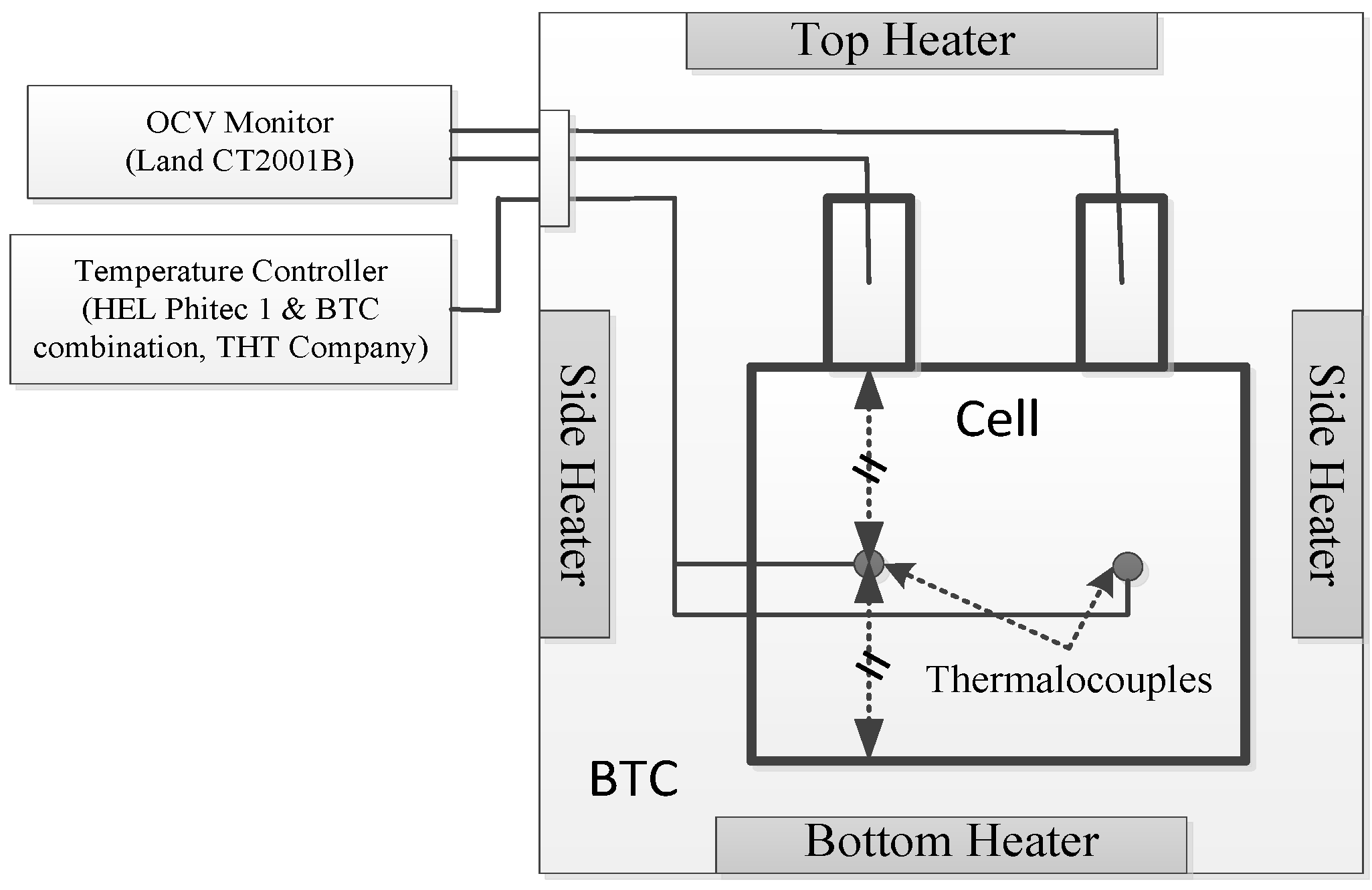
2.2. Thermal Safety Test

Figure 2 displays the experimental setup for the thermal safety test. A cell was placed inside the BTC cavity with two thermocouples symmetrically attached on its surface. Open circuit voltage (OCV) was simultaneously monitored by the Land device during the test process. Previous researches [20,23] showed that cell thermal safety decreases with respect to an increasing SOC. Consequently, all the tests were performed using the worst-case scenario of the fully charged state.
The temperature inside the BTC was controlled by Heat-Wait-Seek-Track computer program [24], whereby the temperature was raised in a stepwise manner by 10 °C. The starting temperature was 40 °C. The heating step was followed by a wait period of 15 min for equilibration. Then, another period of 15 min was taken for searching, and the threshold of self-heating rate was 0.03 °C·min−1. If the temperature increase rate surpassed this threshold during the searching period, the BTC system tracked the temperature of the sample to realize an adiabatic pattern. If the temperature rise was under this threshold or there was no temperature rise, a new temperature step was carried out. The shutdown criteria of the system was when temperature over 200 °C or the pressure in the system over 2 bar.

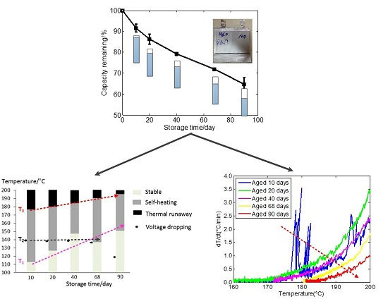
3. Results and Discussion

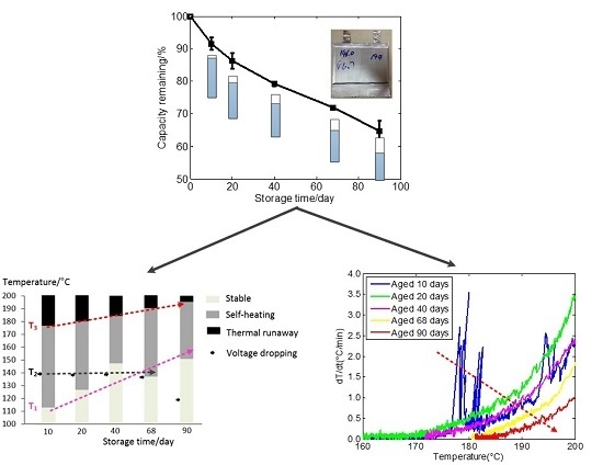
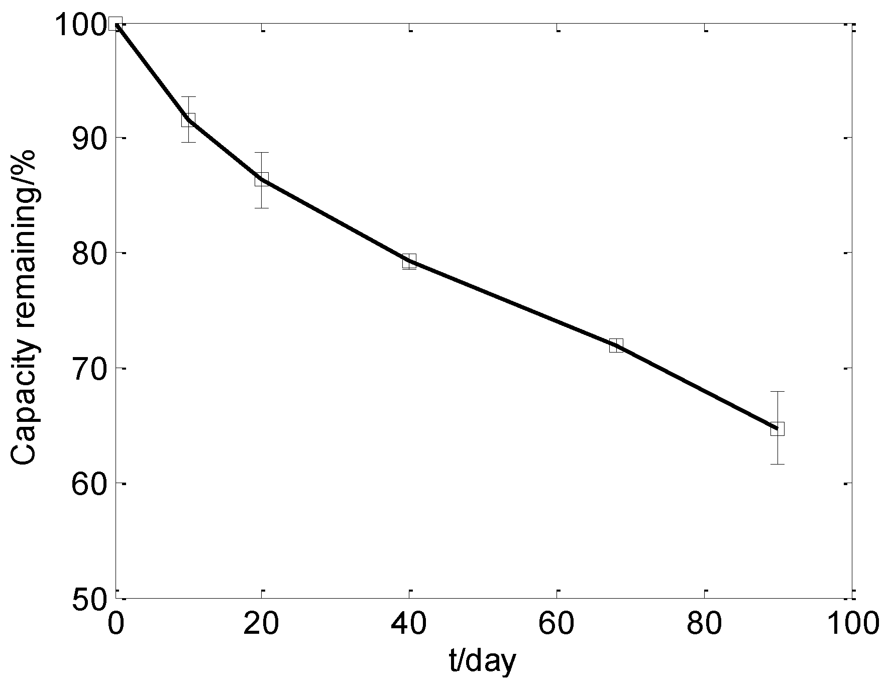
3.1. Cell Capacity Fade during the Storage Test

Figure 3 displays the cell capacity fade during the storing process. The results show that the rate of cell capacity fade decreases during the first 68 days of storage, while it slightly increases after 68 days. The authors have to mention that the turning point might not be exactly the 68th day because cell states were only tested at some specific time points such as the 40th day, 68th day, and 90th day. The capacity of cells faded about 35% after 90 days of storage. It has been reported that the loss of reversible lithium ion (LLI) and the loss of active material (LAM) are the two main reasons for cell capacity fade [25]. The LLI is generally caused by the formation of a SEI film on the surface of the anode electrode, which obeys the time square root regulation [26]. In addition, the formation of SEI film always exists during the whole lifetime of a cell. The cell capacity fade might be blamed on the LLI in the first 68 days of storage. The LAM, in contrast, appears when a cell reaches a specific aging state [25]. Consequently, the slight acceleration of capacity fade might be caused by the combination of LLI and LAM after cells are stored for 68 days.
To study the evolution of cell thermal safety with respect to calendar aging, one cell in each group was chosen for further tests. The capacity remaining of those cells was 92.5%, 85.1%, 78.5%, 71.7%, and 68.0%.

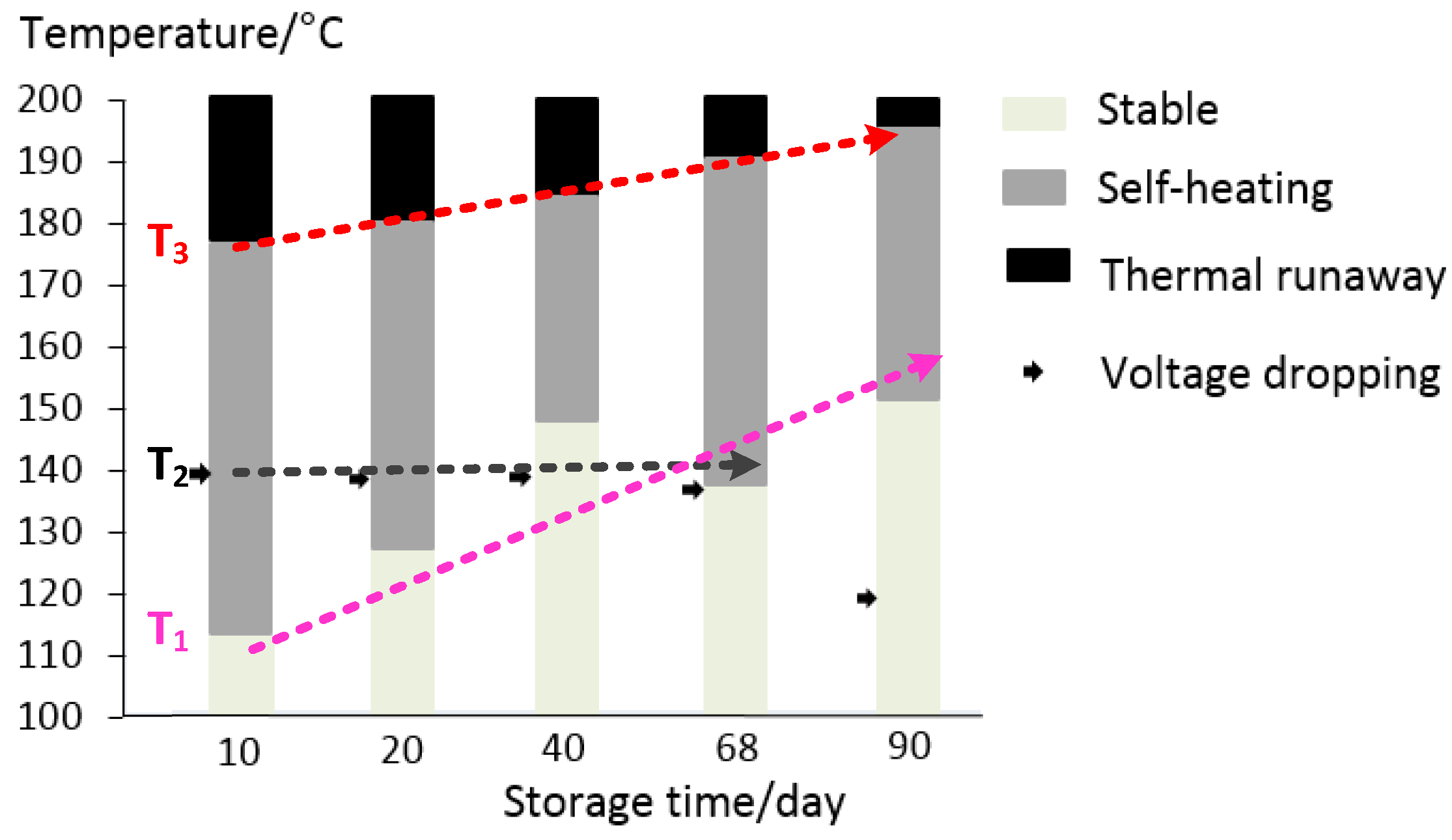
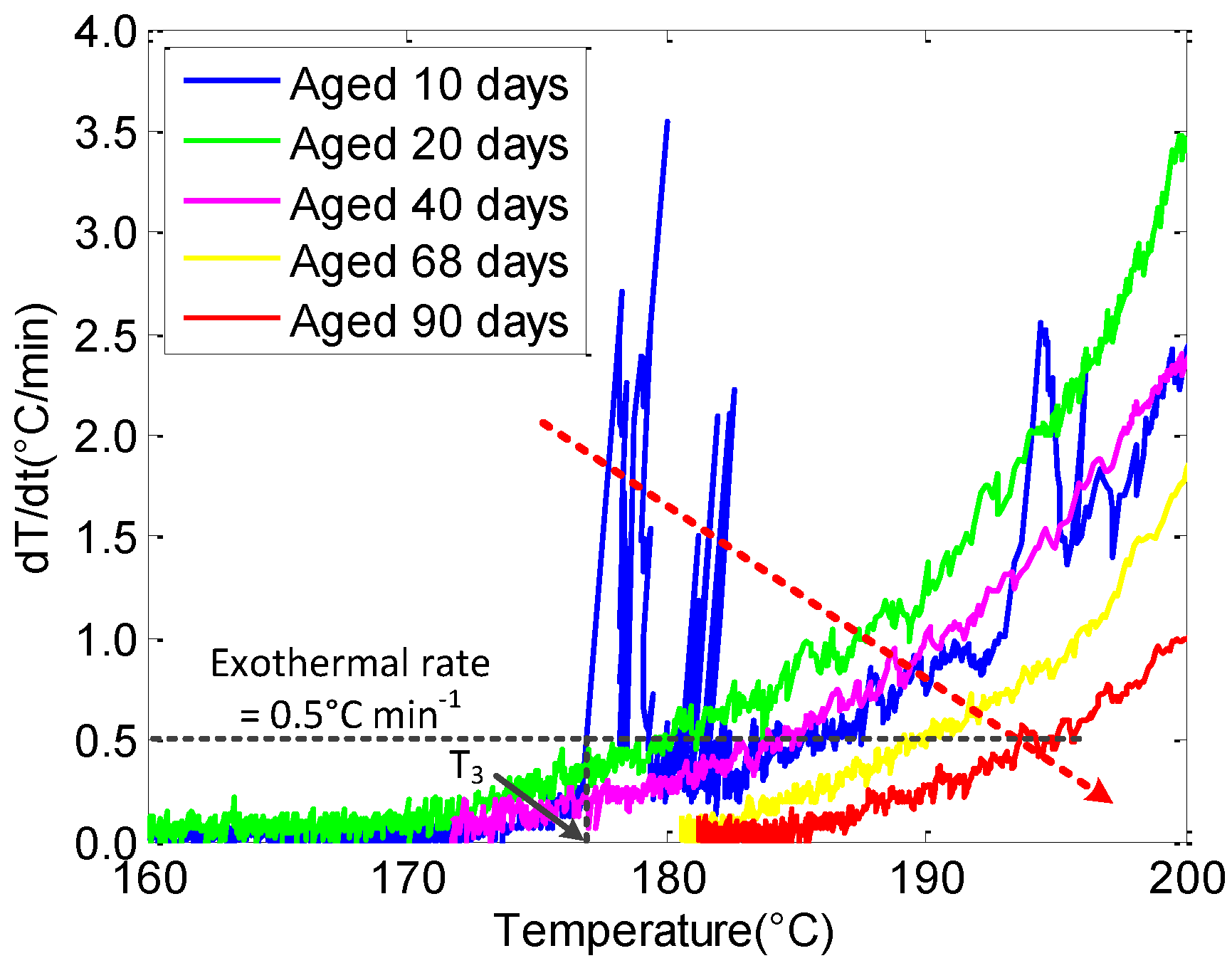
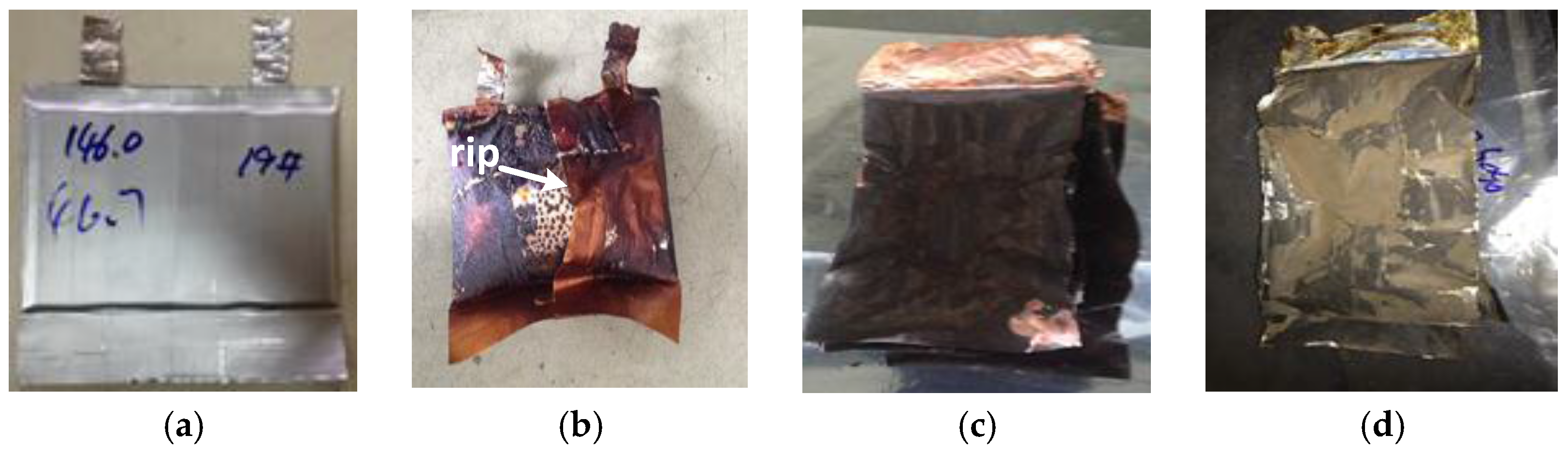
3.2. Thermal Safety Test

Figure 4 shows the images of a cell before and after the thermal safety test. The cell swelled with many brown spots on its surface after the test, as shown in Figure 4b. Generally, the volatilization temperature is about 140 °C for the electrolyte in a lithium-ion cell [17]. The maximum temperature was near 200 °C in the test, which might cause gas releasing side reactions and volatilizing the electrolyte that leads to the swelling of the tested cell. A rip appeared on the surface of the tested cell, as indicated in Figure 4b. Thus, the brown spots should be the residue of the volatilized electrolyte that sprayed out and then condensed on the surface of the cell.
The cathode material is LMO, whose decomposition temperature is higher than 200 °C [27]. The anode material is graphite and its ignition temperature is also much higher than 200 °C. Thus, the composition of both cathode and anode material were unlikely to be changed during the thermal safety test. However, the binder in each electrode might lead to side reactions, reducing the mechanical properties of electrodes. Figure 4c,d shows the images of both electrodes after the test. Both electrodes almost kept their integrity, corresponding to the stability of LMO and graphite during the test. The slight fracture of electrodes might be caused by mechanical stress during the disassembling process, corresponding to the decrease of mechanical properties caused by side reactions of the binder.
Figure 5a depicts the temperature on the cell surface during the test, while Figure 5b displays the variation of the cell voltage and current with respect to temperature. According to those two plots, three critical temperatures can be outlined, which are the initial self-heating temperature (T1), the OCV-drop temperature (T2), and the thermal runaway temperature (T3) [28].
When the temperature reached T1, the cell started releasing heat by itself. With the temperature increasing, the cell voltage suddenly dropped to zero when the cell temperature reached T2, indicating an internal short circuit of the tested cell. Finally, when the temperature reached T3, the cell quickly released heat by itself (dT/dt > 0.5 °C·min−1), causing the fast increase of cell temperature, which might lead to the explosion and burning of the cell. It should be mentioned that the T1 here is a little higher than the self-heating temperature of the cell that has been reported before [28]. This might due to different experiment setups in different tests. For example, the threshold of the self-heating rate in the test was 0.03 °C·min−1, which is higher than the threshold heating rate of 0.01 °C·min−1 [28] or 0.02 °C·min−1 [21,22]. Consequently, self-heating is harder to detect in this test compared to that in others’ work [21,22,28], leading to a higher self-heating temperature.
The temperature time curve in Figure 5a can be divided into five stages by the three critical temperatures and the shutdown temperature (200 °C). In Stage 1, the cell was safe without detectable self-heating (dT/dt < 0.03 °C·min−1), indicating there was no obvious side reactions that quickly release heat inside the tested cell. When the cell came to Stage 2, the cell started releasing heat that could be detected by the BTC, leading to the increase of cell temperature and a long tracking period as shown in the beginning of Stage 2. The initial self-heating should be caused by the decomposition of a part of the metastable SEI film at nearly 120 °C [19,29]. The cell might stop self-heating due to the slow rate of heat releasing that was lower than the threshold of 0.03 °C·min−1. In Stage 3, the cell voltage quickly dropped to zero which should be caused by a micro short circuit inside the cell. The melting temperature for the separator varies from 135 °C to 176 °C according to different compositions of the separator [18]. In this stage, electrons directly transferred from anode to cathode, followed by heat releasing which increased the cell temperature. Then, in Stage 4, a large amount of heat was released due to violent side reactions inside the cell when the temperature reached T3. The released heat caused a fast temperature increase (dT/dt > 0.5 °C·min−1) and led to the thermal runaway of the cell. Finally, in Stage 5, a large amount of cold air was pushed into the chamber of the BTC to protect the test system when the cell temperature was higher than 200 °C. The maximum temperature was a little higher than 200 °C in the final stage because of the fast heat releasing when the cell reached thermal runaway.
Figure 5a shows that T2 is about 40 °C lower than T3. If the temperature increase rate can be estimated, the time remaining before the thermal runaway can be derived. With such information, one can make a wise choice between escaping from the battery or trying to save the battery and other related systems. Voltage and current are always measured for each cell, while temperature is hardly monitored for every cell in a battery system. In addition, the speed of electrical signals transported from the inner part of a cell to the detectors is much faster than the thermal signals. Consequently, it is more convenient and reliable to monitor the thermal safety of cells based on voltage or current signal than temperature.

3.3. The Effect of Aging on Cell Thermal Safety

Figure 6 displays the evolution of cell thermal safety with respect to storage time. Each cell went through three stages during the test: stable, self-heating, and thermal runaway, which were divided by the critical temperatures of T1 and T3. The results show that both T1 and T3 increase with respect to storage time, which means a higher temperature is needed to cause the self-heating and the thermal runaway for cells in aging states. Thus, the thermal safety of cell improves after aging.
T1 is the onset temperature of self-heating, which corresponds to the decomposition of the SEI film. It has been reported that a more pronounced SEI after aging leads to a lower onset temperature for self-heating [21], which contradicts the results. This discordance might come from a different experiment setup among different studies, especially the setting of the threshold for the self-heating rate. For instance, the threshold in this test is 0.03 °C·min−1, which is higher than the threshold heating rate of 0.01 °C·min−1 [28] or 0.02 °C·min−1 [21,22]. Therefore, even though there might be some pronounced SEI that formed during aging, the self-heating of those SEI films cannot be detected if their exothermic rate is less than 0.03 °C min−1.
T2 varied little for cells during the first 68 days of storage. The separator for the tested cells is polyethylene (PE)-based, and its melting point is around 130–140 °C [28]. Since T2 is around 140 °C, the voltage sharply drops at T2 which might correspond to the melting of the separator that led to the micro internal short circuit. The little variance of T2 indicates that storing the battery at 55 °C hardly had an impact on the separator of the tested cell. In contrast, T2 decreased after the cell was stored 90 days. This might be caused by the mechanical stress that was generated during the aging process [30]. Although the separator should not melt at about 120 °C, its physical performance deteriorates at that temperature. Thus, the separator becomes easier to impale with electrode particles, leading to the internal short circuit.
T3 is the onset temperature of thermal runaway, during which various types of side reactions happened together and, after mutual promotion, generated a large amount of heat in a very short time. However, it is hard to distinguish which reactions trigger the thermal runaway, and the increase of T3 cannot be easily blamed on a specific reason. One of the possible reasons could be the formation of SEI film during the aging process which will be further explained in the following discussion.
Figure 7 compares the exothermic rate of cells with different aging states during the process of thermal runaway. At the same temperature, the exothermic rate decreases with respect to storage time, except for the cell aged 10 days, indicating that the safety of the cell improves after aging. The formation of passive film on the surface of both electrodes after the aging of the cell might be related to this phenomenon. On the one hand, the formation of passive film consumed active material, such as the electrolyte and inserted lithium-ion, leaving less active material for side reactions during the stage of thermal runaway. On the other hand, the formed passive film can cover active points that are needed for some side reactions during the process of thermal runaway.

4. Conclusions

In this study, the influence of calendar aging on the thermal safety of 4.6 Ah pouch cells with a LMO cathode was tested by BTC. The voltage and current of the cell were monitored in the meantime. Cells with five different aging stages were acquired for the thermal safety test, and the tested results have been analyzed synthetically.
Three critical temperature points were derived from the test data to compare the thermal safety of cells at different aging states, and they were the self-heating temperature (T1), the OCV-drop temperature (T2), and the thermal runaway temperature (T3). Furthermore, the exothermal rate during the thermal runaway process was also considered. The results show that both T1 and T3 increased, and the cell’s exothermal rate during the thermal runaway process decreased with respect to the storage time. This indicates that the cell thermal safety improved after calendar aging. Thus, cells aged under storage conditions can be deployed in second-life applications while meeting more stringent requirements of thermal safety. In addition, the results show the cell potential suddenly dropped at about 140 °C, which was about 40 °C lower than T3, indicating the voltage could be used as an early warning of thermal runaway in managing a battery system.
Future work will focus on the mechanism that leads to the improvement of thermal safety after calendar aging. Besides, the effect of cycling aging on the cell thermal safety will also be considered to provide guidance for second-life applications of used cells.

Acknowledgments

This work is supported by the National Natural Science Foundation of China under the Grant Numbers of 51207080, 51377097, and 51577104.

Author Contributions

Jianbo Zhang and Ningning Wu conceived and designed the experiments; Laisuo Su and Ying Sun performed the experiments; Laisuo Su and Zhe Li analyzed the data and wrote the paper.

Conflicts of Interest

The authors declare no conflict of interest. The founding sponsors had no role in the design of the study; in the collection, analyses, or interpretation of data; in the writing of the manuscript, and in the decision to publish the results.

References

  1. Dunn, B.; Kamath, H.; Tarascon, J. Electrical energy storage for the grid: A battery of choices. Science 2011, 334, 928–935. [Google Scholar] [CrossRef] [PubMed]
  2. Tarascon, J.M.; Armand, M. Issues and challenges facing rechargeable lithium batteries. Nature 2001, 414, 359–367. [Google Scholar] [CrossRef] [PubMed]
  3. Liu, L.; Zhang, N.Q.; Sun, K.N.; Yang, T.Y.; Zhu, X.D. Influencing factors on safety characteristics of Li-ion batteries. Rare Met. Mater. Eng. 2010, 39, 936–940. [Google Scholar]
  4. Wen, J.W.; Yu, Y.; Chen, C.H. A review on lithium-ion batteries safety issues: Existing problems and possible solutions. Mater. Express 2012, 2, 197–212. [Google Scholar] [CrossRef]
  5. Fergus, J.W. Recent developments in cathode materials for lithium ion batteries. J. Power Sources 2010, 195, 939–954. [Google Scholar] [CrossRef]
  6. Mendoza-Hernandez, O.S.; Ishikawa, H.; Nishikawa, Y.; Maruyama, Y.; Umeda, M. Cathode material comparison of thermal runaway behavior of Li-ion cells at different state of charges including over charge. J. Power Sources 2015, 280, 499–504. [Google Scholar] [CrossRef]
  7. Chen, J.J.; Li, Z.D.; Xiang, H.F.; Wu, W.W.; Cheng, S.; Zhang, L.J.; Wang, Q.S.; Wu, Y.C. Enhanced electrochemical performance and thermal stability of a CePO4-coated Li1.2Ni0.13Co0.13Mn0.54O2 cathode material for lithium-ion batteries. RSC Adv. 2015, 5, 3031–3038. [Google Scholar] [CrossRef]
  8. Zhuang, W.; Lu, L.H.; Wu, X.B.; Jin, W.; Meng, M.; Zhu, Y.D.; Lu, X.H. TiO2-B nanofibers with high thermal stability as improved anodes for lithium ion batteries. Electrochem. Commun. 2012, 27, 124–127. [Google Scholar] [CrossRef]
  9. Dileo, R.A.; Ganter, M.J.; Thone, M.N.; Forney, M.W.; Staub, J.W.; Rogers, R.E.; Landi, B.J. Balanced approach to safety of high capacity silicon-germanium-carbon nanotube free-standing lithium ion battery anodes. Nano Energy 2013, 2, 268–275. [Google Scholar] [CrossRef]
  10. Furuya, Y.; Zhao, W.W.; Iida, T.; Unno, M.; Noguchi, H. Influence of preparation temperature of precursor on the thermal stability of TiO2(B) and its electrochemical property as an anode material in the lithium-ion battery. Electrochemistry 2014, 82, 7–13. [Google Scholar] [CrossRef]
  11. Orendorff, C.J.; Lambert, T.N.; Chavez, C.A.; Bencomo, M.; Fenton, K.R. Polyester separators for lithium-ion cells: Improving thermal stability and abuse tolerance. Adv. Energy Mater. 2013, 3, 314–320. [Google Scholar] [CrossRef]
  12. Zhang, H.Y.; Cao, Y.L.; Yang, H.X.; Lu, S.G.; Ai, X.P. A redox-active polythiophene-modified separator for safety control of lithium-ion batteries. J. Polym. Sci. Polym. Phys. 2013, 51, 1487–1493. [Google Scholar] [CrossRef]
  13. Kim, Y.J.; Lee, S.M.; Kim, S.H.; Kim, H.S. Electrochemical and safety performances of polyimide nano fiber-based nonwoven separators for Li-ion batteries. J. Electrochem. Sci. Technol. 2015, 6, 26–33. [Google Scholar] [CrossRef]
  14. Choi, K.H.; Cho, S.J.; Kim, S.H.; Kwon, Y.H.; Kim, J.Y.; Lee, S.Y. Thin, Deformable, and safety-reinforced plastic crystal polymer electrolytes for high-performance flexible lithium-ion batteries. Adv. Funct. Mater. 2014, 24, 44–52. [Google Scholar] [CrossRef]
  15. Hofmann, A.; Migeot, M.; Thissen, E.; Schulz, M.; Heinzmann, R.; Indris, S.; Bergfeldt, T.; Lei, B.; Ziebert, C.; Hanemann, T. Electrolyte mixtures based on ethylene carbonate and dimethyl sulfone for Li-ion batteries with improved safety characteristics. ChemSusChem 2015, 8, 1892–1900. [Google Scholar] [CrossRef] [PubMed]
  16. Jiang, J.; Dahn, J.R. Effects of solvents and salts on the thermal stability of LiC6. Electrochim. Acta 2004, 49, 4599–4604. [Google Scholar] [CrossRef]
  17. Spotnitz, R.; Franklin, J. Abuse behavior of high-power, lithium-ion cells. J. Power Sources 2003, 113, 81–100. [Google Scholar] [CrossRef]
  18. Yang, H.; Amiruddin, S.; Bang, H.J.; Sun, Y.K.; Prakash, J. A review of Li-ion cell chemistries and their potential use in hybrid electric vehicles. J. Ind. Eng. Chem. 2006, 12, 12–38. [Google Scholar]
  19. Wang, Q.S.; Ping, P.; Zhao, X.J.; Chu, G.Q.; Sun, J.H.; Chen, C.H. Thermal runaway caused fire and explosion of lithium ion battery. J. Power Sources 2012, 208, 210–224. [Google Scholar] [CrossRef]
  20. Roth, E.P.; Doughty, D.H. Thermal abuse performance of high-power 18650 Li-ion cells. J. Power Sources 2004, 128, 308–318. [Google Scholar] [CrossRef]
  21. Roder, P.; Stiaszny, B.; Ziegler, J.C.; Baba, N.; Lagaly, P.; Wiemhofer, H.D. The impact of calendar aging on the thermal stability of a LiMn2O4-Li(Ni1/3Mn1/3Co1/3)O2/graphite lithium-ion cell. J. Power Sources 2014, 268, 315–325. [Google Scholar] [CrossRef]
  22. Fleischhammer, M.; Waldmann, T.; Bisle, G.; Hogg, B.I.; Wohlfahrt-Mehrens, M. Interaction of cyclic ageing at high-rate and low temperatures and safety in lithium-ion batteries. J. Power Sources 2015, 274, 432–439. [Google Scholar] [CrossRef]
  23. Doughty, D.; Roth, E.P. A general discussion of Li Ion battery safety. Electrochem. Soc. Interface 2012, 21, 37–44. [Google Scholar]
  24. Ishikawa, H.; Mendoza, O.; Sone, Y.; Umeda, M. Study of thermal deterioration of lithium-ion secondary cell using an accelerated rate calorimeter (ARC) and AC impedance method. J. Power Sources 2012, 198, 236–242. [Google Scholar] [CrossRef]
  25. Dubarry, M.; Truchot, C.; Liaw, B.Y.; Gering, K.; Sazhin, S.; Jamison, D.; Michelbacher, C. Evaluation of commercial lithium-ion cells based on composite positive electrode for plug-in hybrid electric vehicle applications. Part II. Degradation mechanism under 2C cycle aging. J. Power Sources 2011, 196, 10336–10343. [Google Scholar] [CrossRef]
  26. Ploehn, H.J.; Ramadass, P.; White, R.E. Solvent diffusion model for aging of lithium-ion battery cells. J. Electrochem. Soc. 2004, 151, A456–A462. [Google Scholar] [CrossRef]
  27. MacNeil, D.D.; Lu, Z.; Chen, Z.; Dahn, J.R. A comparison of the electrode/electrolyte reaction at elevated temperatures for various Li-ion battery cathodes. J. Power Sources 2002, 108, 8–14. [Google Scholar] [CrossRef]
  28. Feng, X.N.; Fang, M.; He, X.M.; Ouyang, M.G.; Lu, L.G.; Wang, H.; Zhang, M. Thermal runaway features of large format prismatic lithium ion battery using extended volume accelerating rate calorimetry. J. Power Sources 2014, 255, 294–301. [Google Scholar] [CrossRef]
  29. Battery and Energy Technologies. Available online: http://www.mpoweruk.com/lithium_failures.htm (accessed on 26 February 2016).
  30. Waldmann, T.; Gorse, S.; Samtleben, T.; Schneider, G.; Knoblauch, V.; Wohlfahrt-Mehrens, M. A mechanical aging mechanism in lithium-ion batteries. J. Electrochem. Soc. 2014, 161, A1742–A1747. [Google Scholar] [CrossRef]
Figure 1. Summary of side reactions that happen inside lithium-ion cell at different temperatures [17,18,19]. LCO: LiCoO2; LMO: LiMn2O4; LFP: LiFePO4; NCM: LiNi1/3Co1/3Mn1/3O2; EC: ethylene carbonate; PC: propylene carbonate; DEC: diethyl carbonate; DMC: dimethyl carbonate; PE: polyethylene; PP: polypropylene; and SEI: solid electrolyte interface.
Batteries 02 00012 g001
Figure 2. Experimental setup for the thermal safety test. OCV: open circuit voltage; and BTC: battery test calorimeter.
Batteries 02 00012 g002
Figure 3. Capacity remaining during the storage period for the tested cells.
Batteries 02 00012 g003
Figure 4. Image of a studied cell: (a) before the thermal safety test and (b) after the test; (c) anode electrode and (d) cathode electrode of the cell after the test.
Batteries 02 00012 g004
Figure 5. Thermal safety test for the cell stored 10 days. (a) The variation of cell temperature with respect to time; and (b) the variation of cell voltage and current with respect to cell temperature during the test.
Batteries 02 00012 g005
Figure 6. The evolution of thermal safety of cells with storage time. Dash lines are used to describe the tendency of the critical temperature points with aging.
Batteries 02 00012 g006
Figure 7. The exothermic rate vs. temperature for cells with different aging stages during the process of thermal runaway. The dash line is used to describe the tendency of heating rate.
Batteries 02 00012 g007
Table 1. Nominal specifications of the test cell.
No.ItemSpecification
1Cathode materialLMO
2Anode materialGraphite
3ElectrolyteEC + LiPF6
4Nominal capacity4.6 Ah
5Weight146 g
6Cross section area120 × 180 mm2

