Review

System-Level Compact Review of On-Board Charging Technologies for Electrified Vehicles: Architectures, Components, and Industrial Trends

by
Pierpaolo Dini
1,*,
Sergio Saponara
1,
Sajib Chakraborty
2,3 and
Omar Hegazy
2,3
1
Department of Information Engineering, University of Pisa, Via Girolamo Caruso n.16, 56100 Pisa, Italy
2
MOBI-EPOWERS Research Group, ETEC Department, Vrije Universiteit Brussel (VUB), 1050 Brussels, Belgium
3
Flanders Make, 3001 Heverlee, Belgium
*
Author to whom correspondence should be addressed.
Batteries 2025, 11(9), 341; https://doi.org/10.3390/batteries11090341
Submission received: 8 August 2025 / Revised: 31 August 2025 / Accepted: 9 September 2025 / Published: 17 September 2025

Abstract

The increasing penetration of electrified vehicles is accelerating the evolution of on-board and off-board charging systems, which must deliver higher efficiency, power density, safety, and bidirectionality under increasingly demanding constraints. This article presents a system-level review of state-of-the-art charging architectures, with a focus on galvanically isolated power conversion stages, wide-bandgap-based switching devices, battery pack design, and real-world implementation trends. The analysis spans the full energy path—from grid interface to battery terminals—highlighting key aspects such as AC/DC front-end topologies (Boost, Totem-Pole, Vienna, T-Type), high-frequency isolated DC/DC converters (LLC, PSFB, DAB), transformer modeling and optimization, and the functional integration of the Battery Management System (BMS). Attention is also given to electrochemical cell characteristics, pack architecture, and their impact on OBC design constraints, including voltage range, ripple sensitivity, and control bandwidth. Commercial solutions are examined across Tier 1–3 suppliers, illustrating how technical enablers such as SiC/GaN semiconductors, planar magnetics, and high-resolution BMS coordination are shaping production-grade OBCs. A system perspective is maintained throughout, emphasizing co-design approaches across hardware, firmware, and vehicle-level integration. The review concludes with a discussion of emerging trends in multi-functional power stages, V2G-enabled interfaces, predictive control, and platform-level convergence, positioning the on-board charger as a key node in the energy and information architecture of future electric vehicles.

1. Introduction

1.1. Motivations

The global transition toward electric mobility is accelerating, driven by increasingly stringent environmental regulations, advancements in battery technologies, and the declining cost of lithium-ion cells [1,2,3]. The EV charging system plays a pivotal role in this transformation, directly affecting charging time, energy efficiency, vehicle safety, and battery lifespan [4,5].
However, the design of modern charging systems extends far beyond the dimensioning of a single power converter. It entails a multidisciplinary framework involving interdependent elements such as
  • The overall system architecture (on-board/off-board, single- or multi-stage, with or without galvanic isolation) [6,7];
  • Various power converter topologies (AC/DC and DC/DC, isolated or non-isolated, unidirectional or bidirectional, soft-switching, high-frequency designs) [8,9];
  • Control strategies (voltage and current regulation, digital implementation, PFC, grid synchronization) [10];
  • Battery pack configurations (cell arrangement, thermal management, high-voltage insulation, modularity) [11];
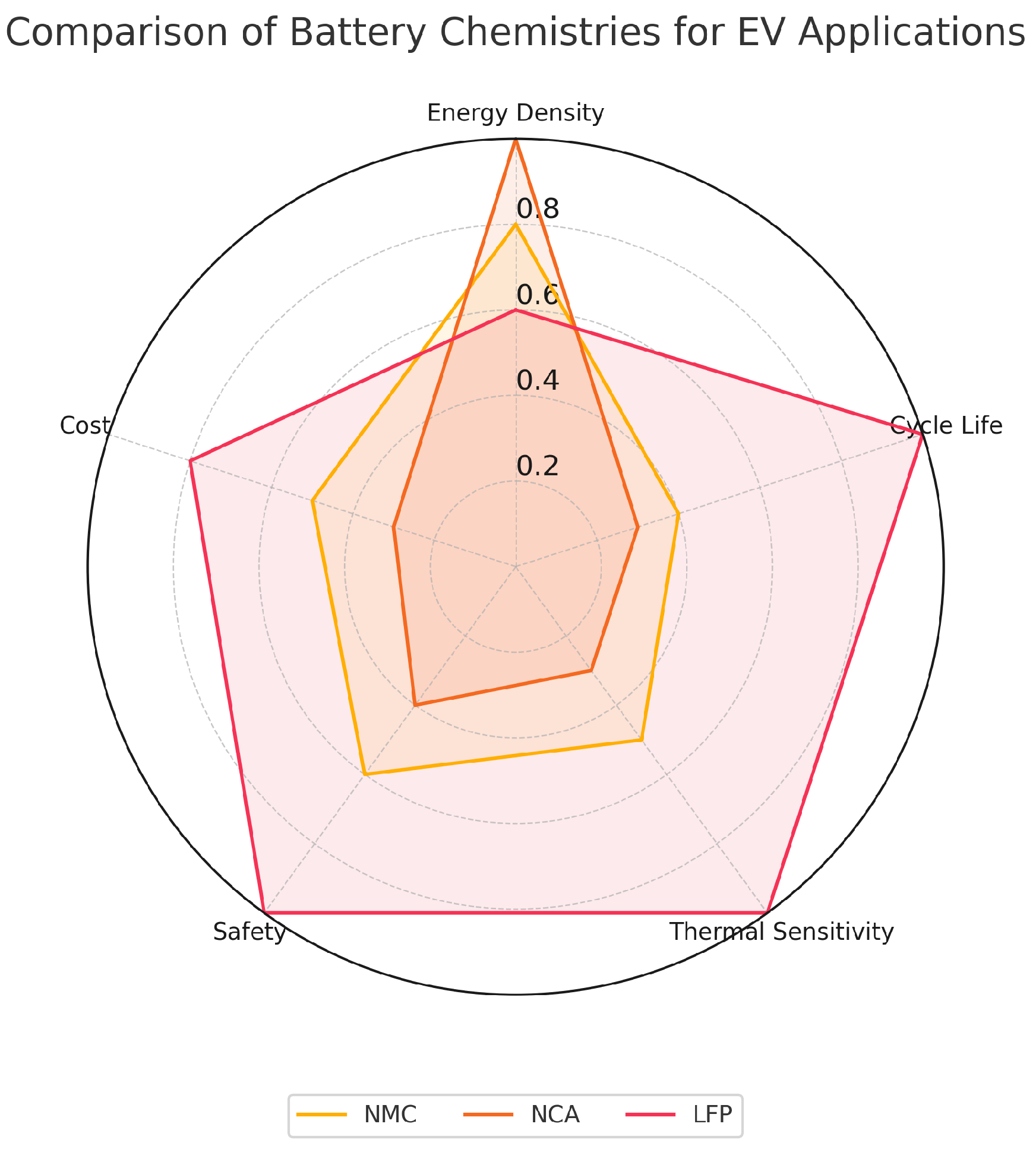
  • Lithium-ion battery chemistries (LFP, NMC, NCA), each with trade-offs in energy density, safety, cost, and fast-charging behavior [3];
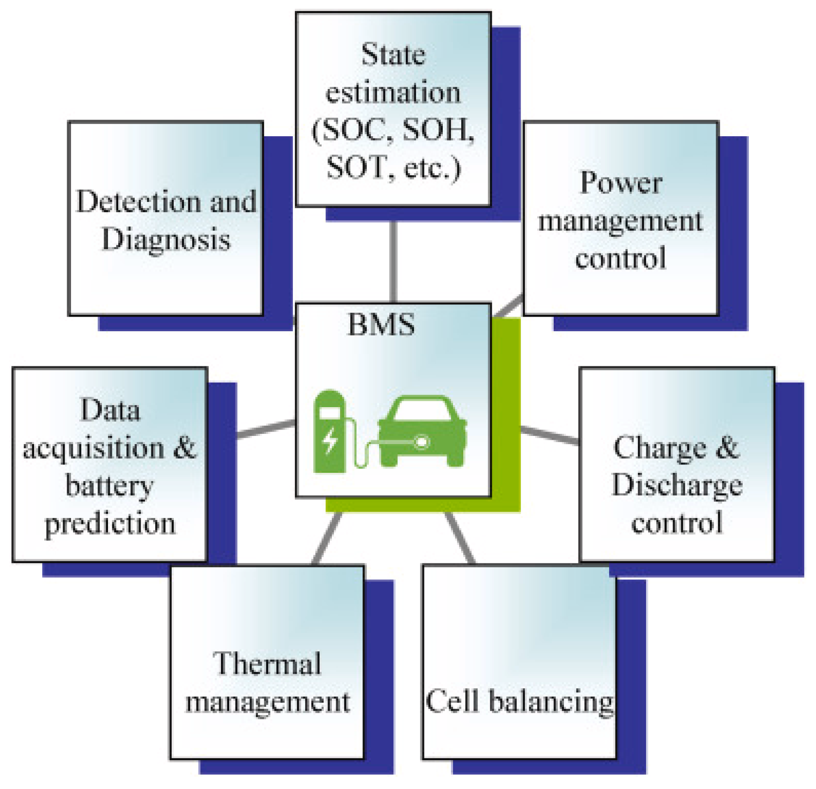
  • BMS integration, including balancing algorithms, state estimation, protection features, and charger communication [12];
  • Essential aspects of system safety and protection, such as insulation monitoring, fault detection, compliance with standards, and cybersecurity [13].
The interaction among these components determines the overall performance and scalability of the system, and design choices must be adapted to the intended use case—ranging from residential AC charging to high-power V2G-enabled infrastructures [7,14].
In particular, the adoption of wide-bandgap (WBG) devices such as SiC and GaN is reshaping converter design, enabling higher switching frequencies, better thermal performance, and greater power density [5,9]. These features are essential to meet the requirements of compact on-board chargers and ultra-fast charging stations.

1.2. Background

An EV charging system transforms electrical energy from the grid into a form suitable for storage within the battery pack. Its functional chain typically includes the following:
  • The AC supply interface, connected to single- or three-phase mains;
  • An active rectifier stage implementing power factor correction (PFC);
  • An isolated DC/DC converter, which adapts the DC bus voltage and provides galvanic isolation;
  • The battery pack, composed of lithium-ion cells managed by a BMS to ensure monitoring, protection, and charge control.
While off-board chargers benefit from fewer constraints in terms of volume and cooling, on-board solutions must achieve compactness, high efficiency, and compliance with electromagnetic and thermal limits [15,16].
Each stage presents specific design challenges: compliance with EMC and grid standards at the input, efficiency and soft-switching in the DC/DC stage, and safety and precision in interfacing with the battery [17,18].
The increasing adoption of bidirectional charging (e.g., V2G, V2H), renewable energy integration, and smart-grid coordination has introduced additional complexity, demanding real-time control, secure communication, and grid code compliance [7,14].
Moreover, the system-level behavior is not the sum of its components: the interactions between control strategies, power stages, battery dynamics, and communication protocols require a holistic co-design approach [2,10].
This review provides a structured and detailed analysis of the complete EV charging system, considering each subsystem—from the grid interface to the battery pack—with dedicated discussions on converter architectures, modulation techniques, practical implementation aspects, and circuit-level analysis supported by schematics and quantitative metrics.

1.3. Paper Contribution

This paper delivers a comprehensive, system-oriented review of EV charging systems based on lithium-ion technology, offering the following contributions:
  • A comparative analysis of power conversion topologies, including AC/DC and DC/DC stages, isolated and non-isolated designs, soft-switching, and bidirectional configurations [8,19];
  • A review of battery pack configurations, including modularity, thermal constraints, and BMS coordination strategies [11,12];
  • A critical discussion of lithium-ion chemistries, namely LFP, NMC, and NCA, with emphasis on their impact on safety, performance, cost, and charging compatibility [3];
  • A comparison between academic solutions and commercial products, highlighting the maturity, scalability, and integration potential of different approaches [17,20];
  • An overview of emerging trends and open challenges, including the integration of WBG semiconductors, cybersecurity in charging infrastructure, multi-vehicle architectures, and the convergence toward unified and flexible system designs [9,21].
The review aims not only to summarize existing technologies but to establish connections between functional blocks, enabling a better understanding of how topological, chemical, and control choices affect the system-level behavior of EV chargers.
The intended audience includes researchers, system architects, and engineers involved in the design, modeling, and deployment of next-generation EV charging solutions.

2. Architecture of Automotive Charging Systems

2.1. On-Board vs. Off-Board

On-board and off-board charging systems represent two complementary approaches to managing energy conversion in electrified vehicles, each characterized by distinct advantages, design constraints, and deployment scenarios [14,22]. See Figure 1 for a schematic comparison.
On-board chargers are fully embedded within the vehicle, enabling charging via standard AC outlets without the need for dedicated infrastructure. This solution offers autonomy and user convenience but is subject to stringent constraints in terms of volume, mass, and thermal dissipation. Power levels typically range from 3.3 to 22 kW, and topologies are optimized for high efficiency and compactness [15,18]. WBG devices play a key role in maximizing power density (3–5 kW/L) while maintaining conversion efficiency above 95% [23].
All charge control resides within the vehicle, with direct coordination between the on-board charger and the BMS. This architecture is well-suited for residential and urban contexts where infrastructure may be limited and charging times less critical [1].
In contrast, off-board chargers relocate the entire power conversion chain outside the vehicle, delivering high-voltage DC directly to the battery interface [13,20]. Freed from the constraints of size and heat dissipation, these systems can reach power levels of 50–350 kW or more, enabling fast or ultra-fast charging (typically <30 min). Modularization, advanced liquid cooling, and redundancy mechanisms ensure service continuity, particularly in fleet or public infrastructure applications [17].
Control and supervision are coordinated via standardized communication with the BMS, commonly over ISO 15118 [24] or OCPP protocols, enabling features such as dynamic load balancing and grid-aware smart charging [7].
The choice between on-board and off-board architectures must reflect the vehicle’s operational profile: while OBCs are ideal for urban mobility and private use, off-board stations are essential in reducing downtime for commercial or long-range applications [4].

2.2. Unidirectional vs. Bidirectional Charging Systems

Charging systems can also be categorized by the directionality of power flow. While unidirectional architectures transfer energy exclusively from the grid to the vehicle, bidirectional systems enable reverse flow, allowing the vehicle to deliver power back to the grid or to local loads [25].
Unidirectional chargers dominate current deployments due to reduced complexity, cost, and certification burden. They rely on simpler control logic and topologies—often Boost or Vienna front-ends combined with isolated DC/DC stages—optimized for high power factor, low harmonic distortion, robust galvanic isolation, and predictable electromagnetic performance [10]. These systems remain the default choice wherever the vehicle behaves as a passive load (e.g., residential/workplace AC charging).
Bidirectional systems require fully controllable AC/DC and DC/DC stages—typically full-bridge, T-type, or DAB-derived converters—operating in both motoring and generating modes [19]. This adds requirements for grid synchronization, reactive power support, islanding protection and interoperability with evolving grid codes [18]. Secure, standards-based communication (e.g., ISO 15118-20, enabling Bidirectional Power Transfer (BPT)) becomes essential, particularly for V2G/V2H/V2L use cases and Plug&Charge with strong PKI [7]. EU policy (e.g., AFIR) and national interconnection rules are accelerating the rollout of smart/bidirectional-ready infrastructure in the second half of the decade, which is expected to increase the addressable base for bidirectional operation. In parallel, global EV deployment and charging-point growth—projected to surge through 2030—provide the scale for broader adoption of bidirectional features [5].
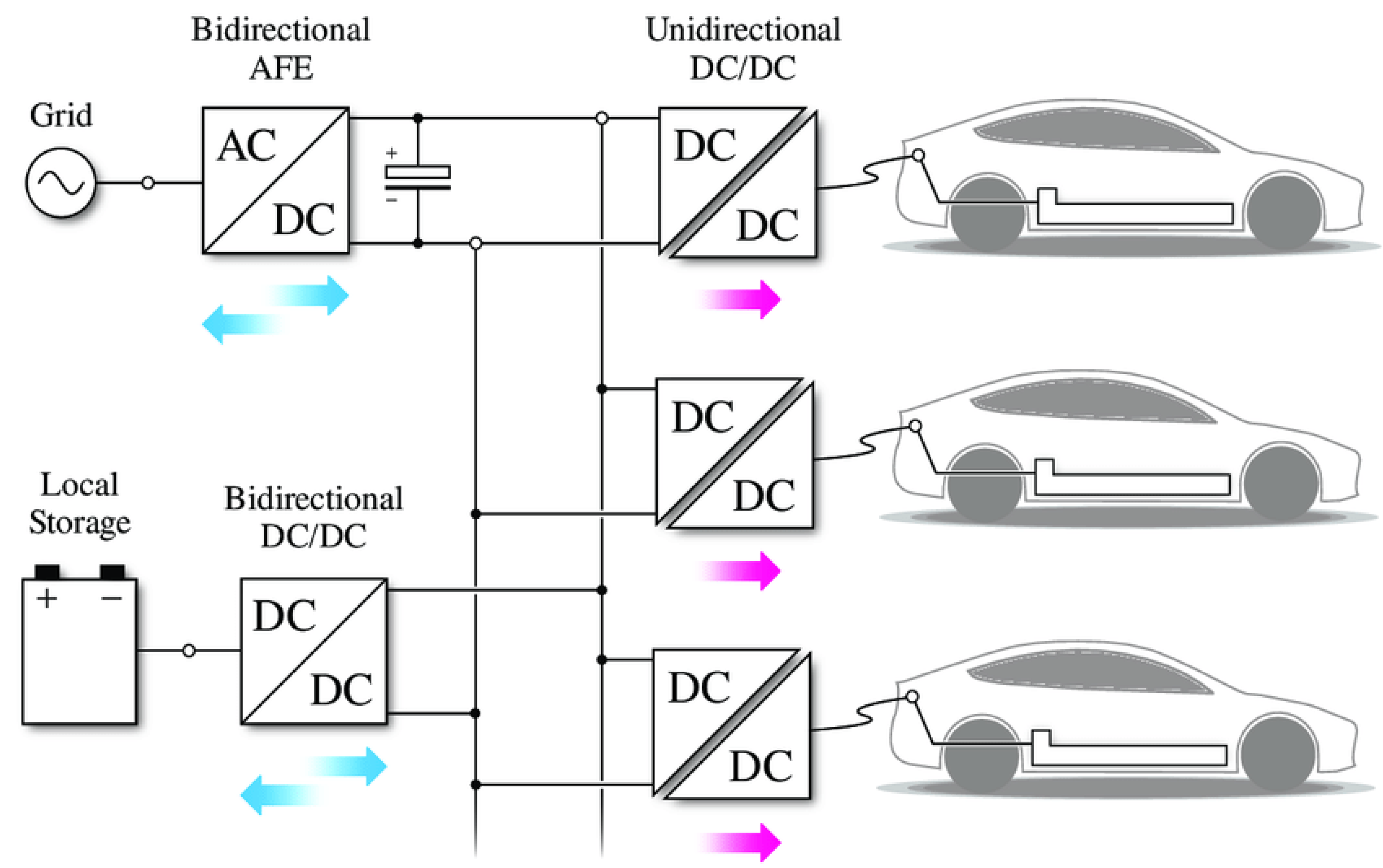
By enabling reverse power flow, vehicles can support peak shaving, frequency/voltage regulation, and backup supply (V2H, V2L), creating system-level value. However, bidirectionality increases hardware/software complexity and cost, introduces additional certification pathways, and raises questions around battery warranty and cybersecurity (see Figure 2). Adoption therefore progresses as standards mature and grid-programs/compensation mechanisms become widely available.

Quantitative Outlook and Distribution Scenarios

Public forecasts consistently project rapid growth in EVs and chargers to 2030, while noting that the share of bidirectional-capable systems will scale with standards enforcement (ISO 15118-20 BPT), grid code readiness and program economics. Building on these trends, Table 1 summarizes scenario-based ranges for the distribution of bidirectional systems across new deployments (light-duty segment). These ranges align with (i) IEA projections for EV and charging growth to 2030, (ii) industry and policy momentum around ISO 15118-20/AFIR, and (iii) analyses highlighting the operational value of V2G/V2X programs. The table is intended as a design-planning aid; actual shares will vary by region and application.

2.3. Energy Flow and Functional Blocks

The charging system architecture can be decomposed into a chain of functional blocks that ensure safe, efficient, and reliable energy transfer from the grid to the battery [26]. Each block contributes to the overall system efficiency and must be optimized accordingly:
  • AC interface: Handles physical connection to the grid, incorporating protective devices, EMI filters, and grid sensing. Ensures synchronization and standard compliance.
  • Active rectifier with PFC: Converts AC to regulated DC with high power factor and low harmonic distortion. Boost and Vienna topologies are common choices.
  • Isolated DC/DC converter: Adapts voltage to battery level and provides galvanic isolation. LLC and DAB are widely used, with magnetic design playing a key role [10].
  • Control and communication unit: Manages regulation, monitors parameters, and exchanges information with the BMS via protocols such as CAN or ISO 15118 [14].
  • Battery and BMS: The battery pack and its management system coordinate SoC/SoH monitoring, balancing, and safety protections during the charging process [12].
The overall charging efficiency can be expressed as the product of the stage efficiencies:
η tot = η AC / DC · η DC / DC · η battery
Typical values for high-performance systems are
  • η AC / DC : 96–98%;
  • η DC / DC : 96–98%;
  • η battery : 98–99%.
Achieving a cumulative system efficiency above 90% requires coordinated optimization of all stages, particularly when compactness and thermal limitations are critical [9,23].

2.4. Design Considerations

The design of charging systems must balance performance, safety, modularity, and integration, taking into account both current technologies and future scalability [21]. Beyond the converter itself, successful OBC design depends on the co-engineering of power stages, magnetics, thermal paths, control/communication layers, and compliance to automotive-grade qualification and safety standards.
  • Galvanic isolation ensures user protection and limits fault propagation. Isolation coordination and insulation materials shall comply with IEC 60664 [27] for creepage/clearance and PD categories, while EV-specific safety and charging requirements are covered by ISO 6469 [28] (electrical safety on-board) and IEC 61851 (conductive charging). In North America, UL 2202 [29] adds product-level requirements for EV charging equipment. Typical verification includes the following: dielectric withstand (hi-pot) on the HF transformer and DC link barrier; insulation resistance at representative DC stress; partial discharge (PD) tests for reinforced insulation; and impulse/surge immunity on the mains side (IEC 61000-4-x) [30]. In operation, insulation monitoring functions per ISO/UNECE EV safety frameworks are coordinated with the BMS. Industrial practice: Tier-1 OBCs used in 11–22 kW platforms implement reinforced isolation across the HF transformer and DC-link barrier and perform end-of-line hi-pot/PD screening before vehicle-level ISO 6469/UNECE approvals (see Section 9).
  • Power scalability and modularity is essential, especially in infrastructure-level or high-power automotive platforms. Modular architectures (e.g., interleaved multi-phase PFC, parallel DC/DC modules) enable N + 1 redundancy, phase shedding at light load, and serviceability. In three-phase 11–22 kW OBCs, two synchronized 11 kW strings are often packaged together, while off-board stations scale as multi-module racks with shared cooling and supervisory control [20].
  • Interoperability and communication relies on standards for the EV–EVSE link and the internal vehicle network. ISO 15118 [31] enables Plug&Charge, certificate-based authentication, and negotiation of charging limits; IEC 61851 defines control pilot/timing; connector interfaces follow IEC 62196/SAE J1772 [32,33]. Inside the vehicle, the OBC exchanges limits, diagnostics, and derating requests with the BMS over CAN/CAN FD; bidirectional/V2G-capable stacks extend this to grid-interactive use cases [14]. Given the connectivity, cybersecurity-by-design (e.g., ISO/SAE 21434) [34] and functional safety (ISO 26262 [35]) are increasingly required in series production.
  • Energy efficiency and thermal management affect not only operating cost but also heatsink/coolant design, enclosure volume, and reliability. Achieving stage efficiencies above 96–98% at both AC/DC and DC/DC is a practical target in modern OBCs; system efficiency results from the product of stage efficiencies and battery acceptance [22]. High-efficiency, soft-switched topologies (e.g., bridgeless totem-pole PFC + LLC/PSFB/DAB) operated with SiC/GaN devices reduce switching losses and magnetic size at a given power density. Thermal design (liquid cold plates, TIMs, even heat-spreaders for planar magnetics) must ensure junction and case temperatures within derating limits across ambient/vibration profiles typical of automotive duty.
  • EMC/EMI and grid power quality drive front-end filter design and control bandwidth. Automotive EMC is typically validated against UNECE R10/CISPR 25 for radiated/conducted emissions and immunity, while grid-connected behavior (THD, PF, flicker, immunity) follows the relevant IEC 61000 families at equipment or system level. Resonant or three-level front-ends help reduce dv/dt and shrink EMI filters; LCL variants with selective damping are preferred in three-phase designs when acoustic/size constraints are stringent.
  • Cost, footprint, and manufacturability are crucial for on-board systems, where space, mass, and BOM must be minimized without compromising EMC or thermal performance [1,15]. While WBG devices increase device cost versus Si/IGBT, they typically enable smaller magnetics/filters and lower cooling overhead, improving total cost of ownership at scale. Integration trends (shared coolant loops, co-packaging OBC with HV DC/DC or traction inverter power modules) further reduce volume and parts count in series production.
  • Reliability and environmental robustness require qualification against automotive stressors (thermal cycling, humidity, corrosive atmospheres, mechanical shock/vibration). Design of the HF transformer, busbars, and large passives should consider mechanical fixation, potting/impregnation, and material choices resilient to vibration-induced fatigue (e.g., per ISO 16750 [36] test profiles), as well as insulation life models versus thermal hotspots.
These design aspects underpin the technological decisions presented in the subsequent sections, including the selection of topologies, semiconductor devices, and control methods, and they are reflected in commercial realizations (e.g., bridgeless totem-pole PFC combined with LLC/PSFB, WBG switches, and planar magnetics) discussed in Section 9.

3. AC/DC Front-End in Automotive Charging Systems

The AC/DC front-end constitutes the first stage of the charging system, converting alternating current from the grid into regulated direct current for downstream conversion or direct battery charging. Its performance is critical to the overall system in terms of efficiency, power quality, and regulatory compliance [37,38].
This section provides a detailed analysis of the main AC/DC converter topologies adopted in on-board and off-board EV chargers. The discussion is organized by input configuration (single-phase or three-phase), application power range, directionality, and the presence of galvanic isolation [39]. Each topology is described in terms of operational principles, performance metrics, and integration aspects, with emphasis on practical implementation and technology readiness [40].

3.1. Boost Power Factor Correction Converter

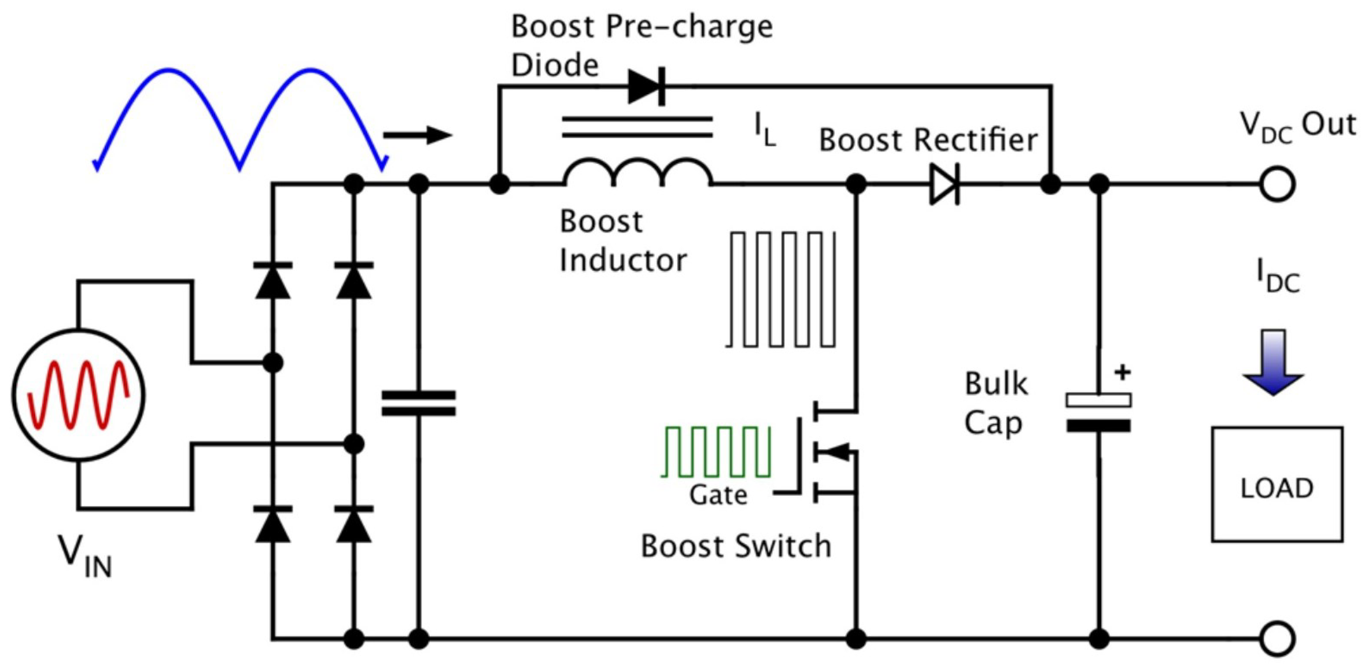
The Boost PFC is the reference topology for single-phase on-board chargers up to 3.3 kW [41]. Its main purpose is to shape the input current to follow the grid voltage waveform, thus achieving high power factor and low harmonic distortion.
Figure 3 shows the basic schematic, where a diode bridge is followed by a Boost stage operating in either CCM or BCM. The output voltage is regulated by high-frequency PWM control, and efficiency can exceed 95% with WBG switches [42].
The DC output voltage is governed by
V out = V in 1 D
The inductance is estimated by
L = V in · D f s · Δ I L and I L , peak = I in , avg + Δ I L 2
The output capacitor is dimensioned as
C o = I o · D f s · Δ V o
Control is typically implemented via average current mode, with optional digital enhancements (e.g., voltage feedforward, protections). The small-signal transfer function from duty to output is
G v d ( s ) V in 1 D · 1 1 + s R C with R = V out I o

3.1.1. Operating Regimes and Practical Trade-Offs

In CCM, the inductor current ripple is low, RMS currents are minimized, and conduction losses are reduced at the expense of larger magnetic components; in BCM/CRM, the switch turns on at (near) zero inductor current, improving turn-on losses and diode recovery, but RMS currents are higher and the control must handle wide-frequency excursions over the mains cycle. Device/EMI stress also depends on the choice of rectifier (SiC diode vs. synchronous MOSFET) and on the layout parasitics at the bridge–Boost interface.

3.1.2. Efficiency Sensitivity to Switching Frequency ( f s )

The stage efficiency is driven by the balance between conduction losses and frequency-dependent losses of semiconductors and magnetics:
η P o u t P o u t + P cond ( I rms ) + P sw ( f s ) + P mag ( f s ) + P gate / ctrl .
A first-order switching loss model for the Boost switch gives
P sw 1 2 V d s I l o a d ( t on + t off ) f s ,
so that P sw / f s > 0 , whereas the magnetic/core loss can be approximated (ferrite) as
P mag ( f , B ) k h f B α + k e f 2 B 2 ,
with 1.6 α 2.2 . Increasing f s reduces L and C (and thus volume) but raises P sw and P mag ; conversely, lowering f s enlarges passives and can degrade dynamic response. An optimal f s region arises where the marginal increase of P sw + P mag balances the marginal reduction of passive size/RMS losses.
Wide-bandgap devices (SiC/GaN) lower ( t on + t off ) and output charge, flattening the P sw ( f s ) slope and shifting the optimum to higher f s ; this enables smaller passives and higher power density at constant efficiency. Practically, designers choose f s to meet (i) ripple targets (e.g., Δ I L 20 40 % of the valley current at V ^ in ), (ii) EMI limits (dv/dt, conducted/radiated), and (iii) thermal headroom at worst-case line and temperature. Note that at elevated temperature, R DS ( on ) rises and core losses increase, making the efficiency more sensitive to f s than at room temperature.

3.1.3. Design Notes for WBG-Based Boost PFC

  • Inductor: Choosing f s and Δ I L fixes L; with higher f s , the copper AC losses and core loss terms may dominate unless the winding and core material are optimized (e.g., litz wire, low-loss ferrites).
  • Switch/diode: SiC MOSFET + SiC diode (or synchronous MOSFET) reduces recovery and improves high-line ZVS margin in BCM; gate-driver layout and d V / d t management are crucial for EMI.
  • EMI: Higher f s narrows the spectrum but increases common-mode noise due to faster edges; input EMI filters (L, LC/LCL with damping) must be co-designed with layout to avoid peaking near the control bandwidth.
  • Light-load: Frequency foldback and phase-shedding (in multi-phase variants) help maintain efficiency when the mains current is small near the zero crossings.
WBG devices allow for operation above 100 kHz, reducing passive size but increasing EMI design challenges [43]. Despite its simplicity, the Boost PFC remains widely adopted in compact AC/DC front-ends.

3.1.4. Efficiency Versus Switching Frequency: Comparative Outlook

To better illustrate the trade-off, Table 2 summarizes the typical efficiency behavior of Boost PFC stages implemented with different switch technologies. The table highlights how the adoption of WBG devices (SiC, GaN) shifts the optimal operating frequency toward the hundreds of kilohertz range, enabling reduced passive size while maintaining or improving conversion efficiency compared to legacy Si or IGBT solutions.

3.2. Interleaved Boost PFC

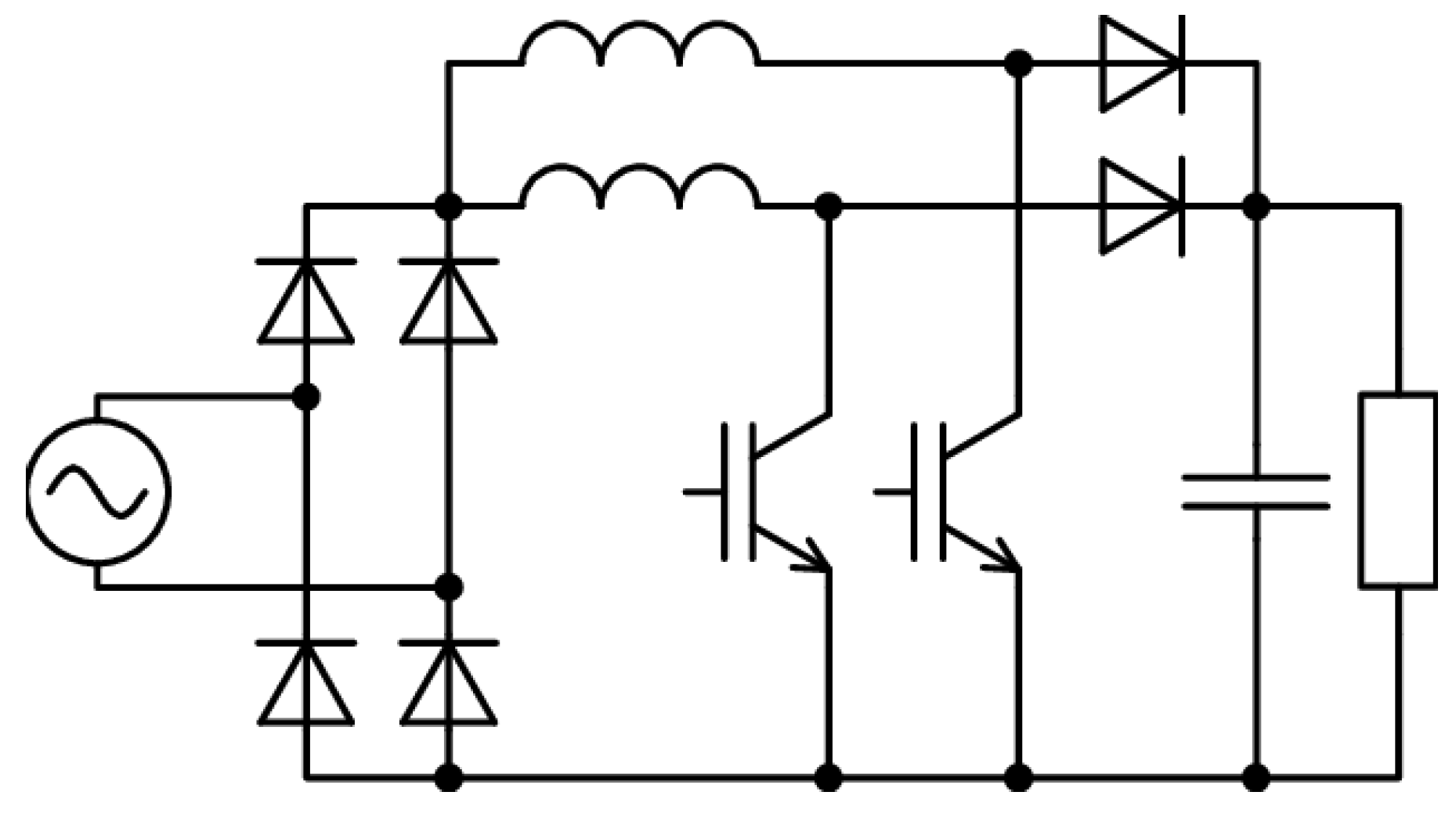
The interleaved Boost PFC (see Figure 4) enhances the basic topology by operating multiple phases in parallel with phase-shifted PWM [41]. This approach reduces input and output ripple, improves thermal distribution, and enables higher power density (up to ∼6.6 kW).
It is especially suitable for medium-power OBCs, leveraging the partial ripple-cancellation effect. Each phase operates with its own inductor, switch, and diode (or synchronous rectifier), while control is typically centralized and implemented digitally. For N phases, the interleaving angle is 360 / N , and the effective input/output ripple scales with the vector sum of phase currents, improving as the duty-cycle departs from the cancellation zeros.
The output voltage remains as
V out = V in 1 D
The per-phase inductor design is
L = V in · D f s · Δ I L and I L , peak = I in , avg N + Δ I L 2
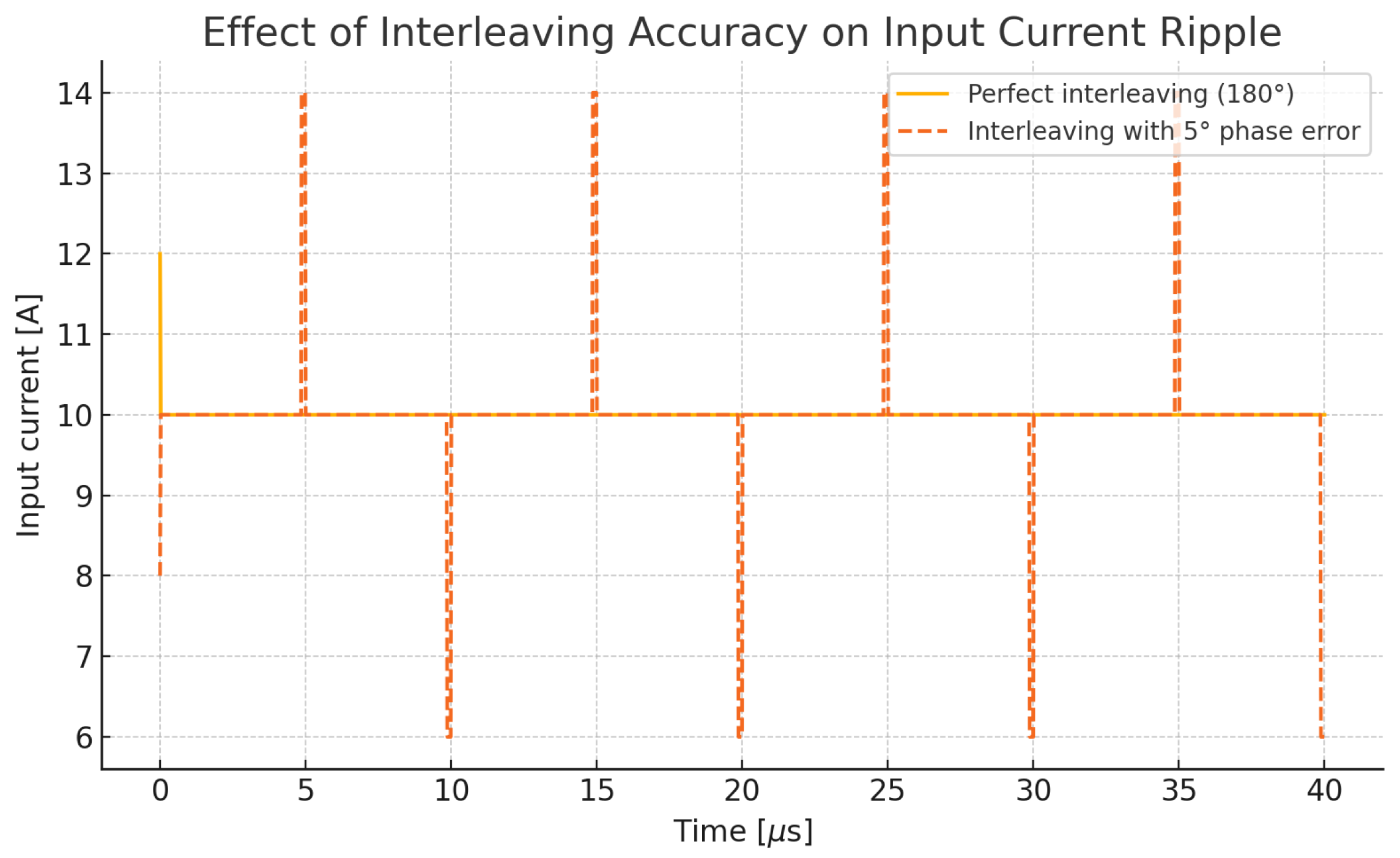
Key benefits include reduced stress on components, lower EMI, and better scalability. However, accurate current balancing among phases is essential to avoid circulating currents, thermal runaway of a single leg, and EMI peaking (see Figure 5 and Table 3).

3.2.1. Current Balancing Methods (Design Guidelines)

Several techniques exist to enforce current sharing:
  • Passive droop (series R or DCR emulation). A small effective resistance introduces a proportional droop, so that higher current phases see a reduced voltage reference. The droop coefficient can be expressed as
    k d = Δ V Δ I R s · G cs ,
    where R s is the physical (or emulated) sense resistance and G cs is the current-loop gain. Typical design targets set k d such that current sharing error remains < 5 % across load and temperature.
  • Average current-mode control. Each phase tracks I / N , enforced via digital averaging of measured currents. Provides excellent accuracy at the cost of higher sensing and control effort.
  • Master–slave bus. A single master phase defines current reference; slave phases synchronize via a dedicated bus. Simpler but slower dynamic equalization.
  • Inductor coupling or Interphase transformer (IPT). Magnetic coupling naturally enforces current sharing and further suppresses ripple.
  • Digital calibration and trimming. Compensation of offsets and mismatches in sensors, gate drivers, and dead-times via firmware, improving long-term balance.

3.2.2. Implementation Notes to Avoid Practical Errors

  • Match inductor values across phases (<±3%).
  • Use symmetric PCB layout to equalize parasitics and minimize circulating currents.
  • Synchronize sampling to PWM edges to avoid sensing skew (see Figure 5).
  • Apply phase-shedding under fault/thermal stress to maintain stable operation.

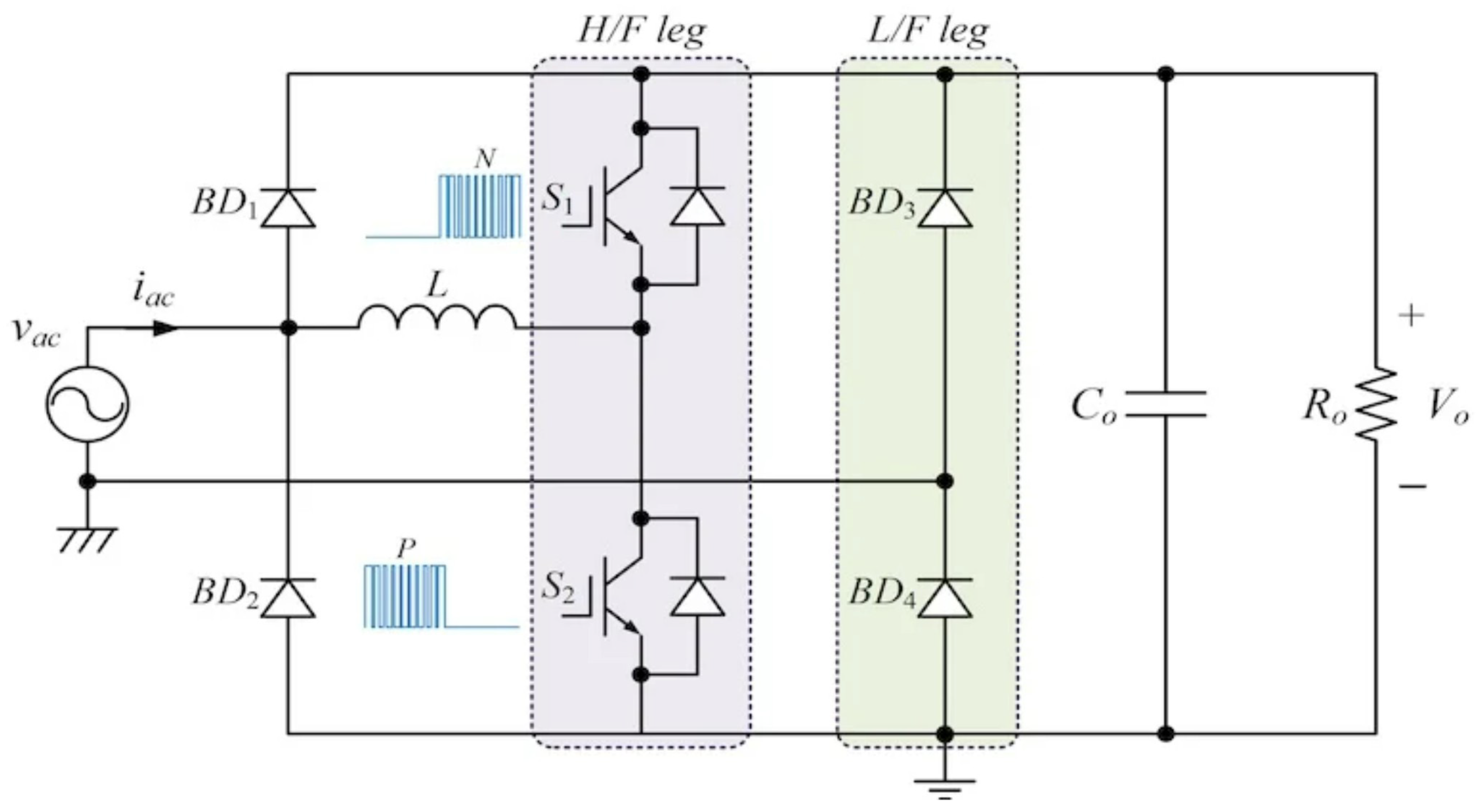
3.3. Bridgeless Totem-Pole PFC

This topology (see Figure 6) removes the input diode bridge, replacing it with actively controlled fast switches [41,42]. It achieves higher efficiency (up to 99%) and is ideal for compact on-board or wallbox systems in the 1.8–7 kW range.
It relies on fast GaN or SiC switches in a totem-pole arrangement and supports bidirectional operation if synchronous switches are used on the low-frequency leg.
Boost voltage relation:
V out = V in 1 D L = V in · D f s · Δ I L I L , peak = I in , avg + Δ I L 2 C o = I o · D f s · Δ V o
While ZVS and ZCD techniques can be applied to mitigate losses, the topology demands careful EMI management and tight control. Its high efficiency and reduced BOM make it an attractive solution for high-frequency, high-density chargers [37].

3.4. Vienna Rectifier

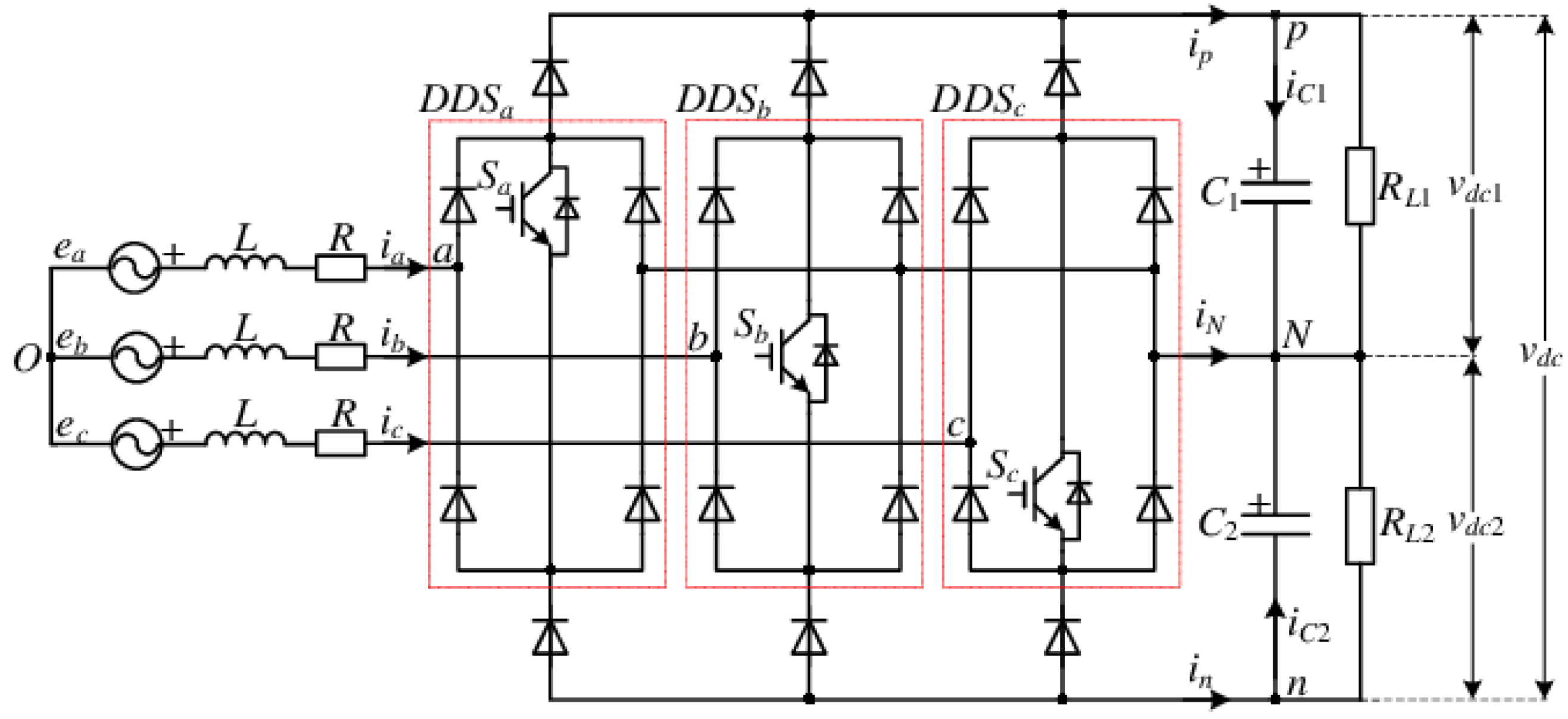
The Vienna rectifier (see Figure 7) is a unidirectional three-phase topology ideal for off-board chargers and industrial stations in the 10–20 kW range [37,43]. It features three switches (one per phase) working in coordination with a three-level diode rectifier.
It achieves near-unity power factor with low THD using space vector modulation and offers reduced voltage stress per switch (typically 450 V).
Output capacitor and inductor design:
C dc = I o · D f s · Δ V dc L = V line · ( 1 D ) f s · Δ I
Control complexity increases due to midpoint stabilization and SVM implementation, but the topology remains compact and efficient (>97%) [40].

3.5. T-Type PFC Converters

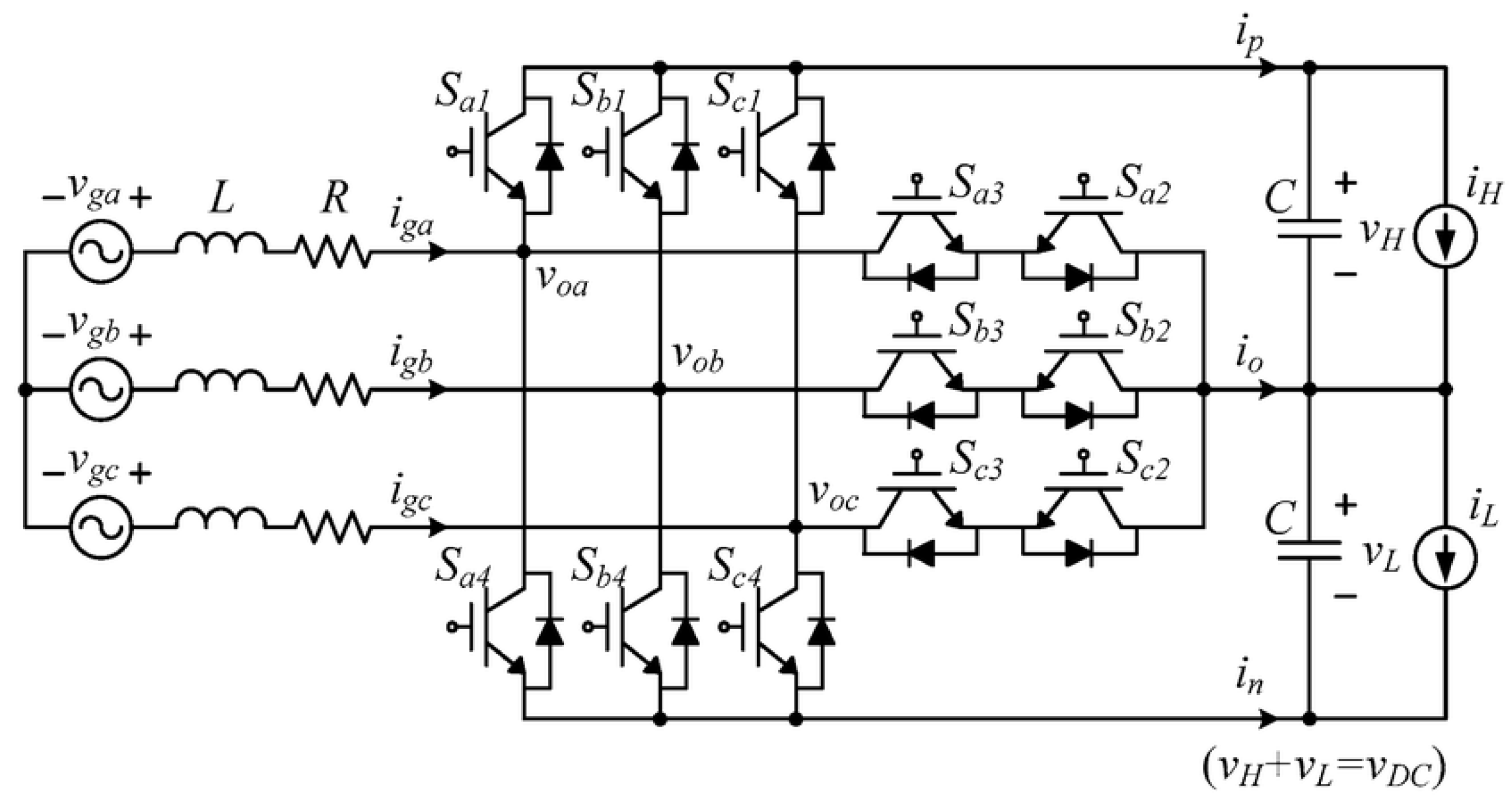
The T-Type topology (see Figure 8) offers a three-level structure with fully active control, removing diodes and enabling improved current shaping [44]. It is suitable for 10–30 kW three-phase systems where EMI, efficiency, and thermal performance are critical.
Compared to Vienna, it provides full modulation control at the cost of higher gate count and switching complexity.
Inductor and capacitor sizing:
L = V line · D f s · Δ I C dc = I o · D f s · Δ V dc
The three-level nature allows reduced dv/dt, smaller filters, and better harmonic performance. Control strategies mirror those of Vienna but include extra degrees of freedom due to the full bridge leg per phase [45].

3.6. Comparison of AC/DC Front-End Topologies: Key Metrics

Table 4 provides a comparative overview of the main AC/DC front-end topologies used in electric vehicle chargers, highlighting key parameters such as power range, input configuration, galvanic isolation, bidirectional capability, and power factor correction. The comparison also includes efficiency, ripple current, total harmonic distortion, passive component requirements, and control complexity, offering a useful reference for selecting the most suitable solution according to the target power level and application requirements.

4. AC-Grid Interface in Automotive Charging Systems

The interface between the power converter and the AC grid plays a crucial role in ensuring electromagnetic compatibility, power quality, and compliance with grid codes [49,50]. This section reviews the most relevant passive filter topologies used to mitigate switching harmonics and shape the injected current waveform [51,52]. Although primarily passive, these filters directly impact converter stability, efficiency, and system-level integration, particularly in fast-charging or high-power applications [53]. To increase credibility beyond theoretical formulations, representative measurement results reported in the literature and in automotive prototypes are included, highlighting the achieved attenuation, harmonic distortion, and efficiency impact.

4.1. Pure Inductive Filter

The L filter is the simplest solution, consisting of a single series inductor between the converter and the grid. Its impedance grows with frequency, attenuating high-frequency components:
G ( s ) = 1 L s + R .
It is employed in low-complexity systems (e.g., industrial UPS, diode rectifiers) where EMI requirements are moderate [50,54]. Measured data confirm that with L = 2.5 mH in a 3.3 kW single-phase charger, the current ripple at 20 kHz is reduced by approximately 15 dB, yielding a grid current THD of 7 % (vs. >20% unfiltered). Efficiency remains above 98.5% due to minimal inductor losses.

4.2. LC Filter

An L C filter adds a shunt capacitor, forming a second-order low-pass:
G ( s ) = 1 1 + s 2 L C , ω 0 = 1 L C .
This improves selectivity but introduces resonance. Capacitor sizing is typically 2–5% of the apparent power, while the inductor sets the current ripple. Experimental studies on 6.6 kW OBC prototypes show that an L C filter with L = 1.5 mH, C = 5 μ F achieved >25 dB attenuation of switching harmonics, reducing input current THD to 4 % , though efficiency decreased by ∼0.3% due to reactive current circulation [55].

4.3. LCL Filter

The LCL filter splits inductance between the converter and grid side:
G ( s ) = 1 s ( L 1 L 2 C f s 2 + ( L 1 + L 2 ) ) , ω 0 = L 1 + L 2 L 1 L 2 C f .
This structure provides higher attenuation with smaller inductors. It is the de facto standard in three-phase grid converters [50,55]. Measurements in 11 kW three-phase OBC demonstrators show that an LCL ( L 1 = L 2 = 0.7 mH, C f = 6 μ F) reduced current ripple by ≈40 dB at f s = 50 kHz, achieving grid current THD < 2 % and PF > 0.99 . However, additional damping (see below) was necessary to suppress resonance around 3 kHz.

4.4. LCL with Series or Parallel Damping

Adding a series resistor R d with C f improves stability:
G ( s ) = L 2 C f s L 1 L 2 C f s 3 + R d L 2 C f s 2 + ( L 1 + L 2 ) s + R d .
Practical tests confirm that a small R d (0.5–1 Ω ) suppresses resonance, stabilizing current loop dynamics with negligible efficiency penalty ( < 0.2 % ). Parallel RC damping achieves similar stability with even lower losses [56].

4.5. Resonant Traps and Selective Filters

Tuned resonant traps and selective damping are employed to target narrowband harmonics (e.g., f s or 2 f s ). Experimental validation on a 22 kW wallbox charger [57] shows that a tuned trap at 100 kHz reduced EMI peaks by 20 dB, enabling compliance with CISPR 25 Class 5 limits, while maintaining overall converter efficiency above 96.5%.

4.6. Discussion

These measured results confirm that passive filter design choices in OBCs are consistent with theoretical transfer functions, but their credibility depends on experimental validation of attenuation, THD, and efficiency trade-offs (see Table 5). In practice, LCL with damping is the most common solution for three-phase OBCs, while LC suffices for single-phase, with resonant traps added where EMI limits are stringent. The table demonstrates that attenuation levels of 20–40 dB and grid THD below 2–5% are consistently achievable in prototypes, with efficiency penalties typically below 1%. This aligns analytical design with real-world measurements, strengthening the validity of the presented models.

5. DC/DC Converters in Automotive Charging Systems

DC/DC converters provide the voltage adaptation and galvanic isolation required between the AC/DC front-end and the high-voltage battery pack. The choice of topology directly impacts the converter’s power density, control complexity, soft-switching capability, and suitability for bidirectional operation [58,59].
This section reviews the main isolated topologies adopted in OBC systems, spanning from auxiliary low-power stages to high-power main converters [60,61].

5.1. Flyback Converter

The flyback converter is one of the most widely used isolated DC/DC topologies due to its simplicity and low component count. In OBC systems, it is commonly adopted for auxiliary power rails, such as 12 V or 5 V derived from a 400 V DC bus [60,61].
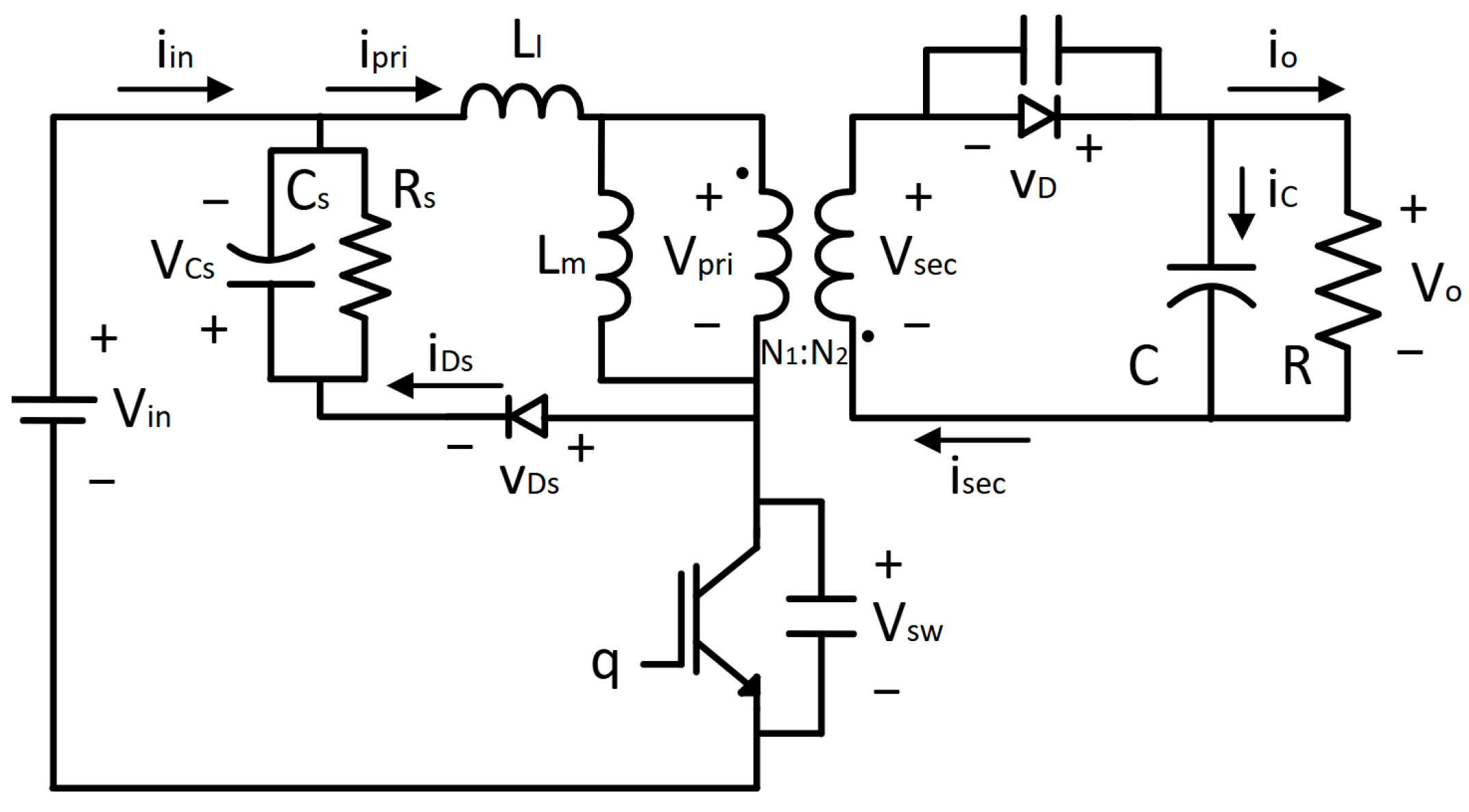
As illustrated in Figure 9, the flyback stores energy in the magnetizing inductance L m during the switch-on interval and transfers it to the output when the switch turns off.
i p ( t ) = V in L m t , V out = V in · N s N p · D 1 D
L m = V in · D · T s Δ i p , B max = L m I p , peak N p A e
C out I out · D · T s Δ V out , V RRM V out + N s N p V in
Although simple and cost-effective, the flyback is limited to low power (typically <300 W), as efficiency drops significantly with load due to high voltage stress and switching losses. It is unsuitable for main traction charging but remains ideal for low-power auxiliary conversion [60].

5.2. Forward Converter

The forward converter improves efficiency and regulation over the flyback, making it suitable for mid-power auxiliary stages in OBCs [62,63].
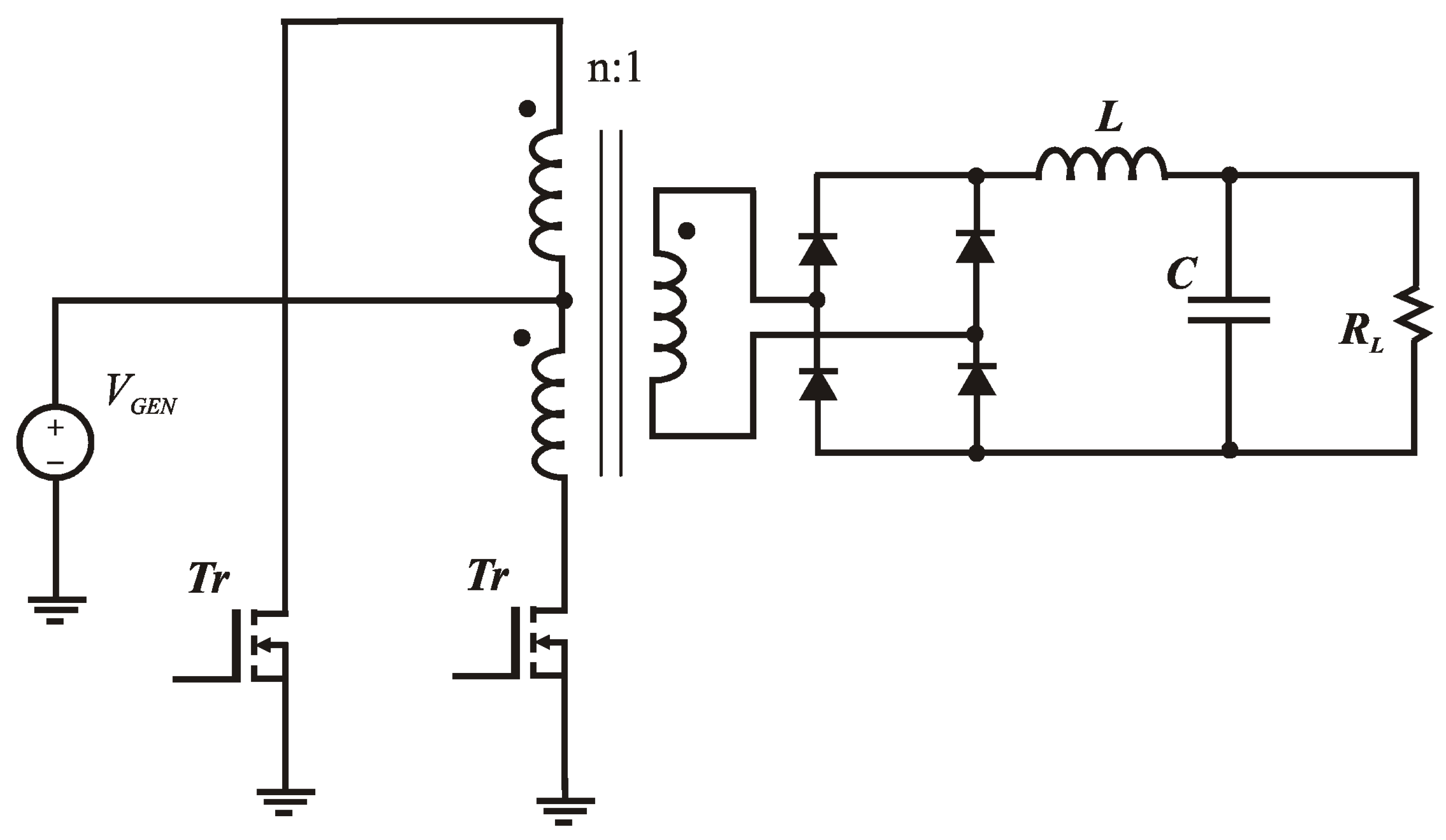
In this topology (Figure 10), energy is transferred to the output during the switch-on interval. A demagnetizing winding N r is used to reset the transformer core and prevent saturation.
V out = V in · N s N p · D , L V out ( 1 D ) Δ I L · f s , C Δ I L 8 f s · Δ V out
D max = V reset V in + V reset
Compared to the flyback, the forward topology avoids the storage/release cycle in the transformer, reducing core stress and improving efficiency. However, it requires additional components (e.g., reset winding, freewheeling path) and is typically limited to 1 kW in OBC contexts.

5.3. Push–Pull Converter

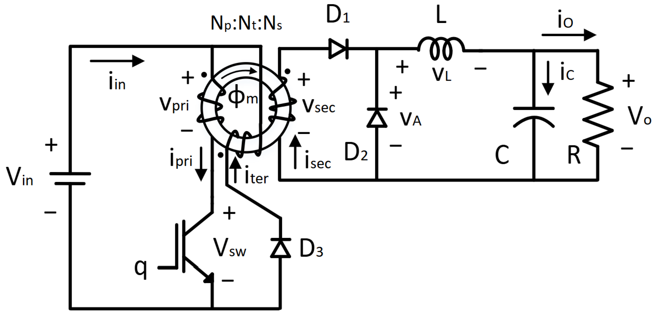
The push–pull converter (see Figure 11) is suitable for isolated DC/DC conversion in the 1–2 kW range, offering symmetrical drive and good transformer utilization [64,65].
The topology alternates q 1 and q 2 to apply ± V in to the transformer primary, providing bidirectional flux excitation.
V out = 2 · V in · N s N p · D , L V out ( 1 2 D ) Δ I L · f s , C Δ I L 8 f s · Δ V out
The main benefit is compact magnetics and effective core utilization, but performance is sensitive to mismatch in winding or drive timing. Saturation risks due to imbalance require precise layout and control [66].
Push–pull converters remain a viable option in low- to mid-power isolated stages within automotive environments, though largely supplanted by more robust half-bridge and resonant alternatives in high-efficiency OBCs.

5.4. LLC Resonant Converter

The LLC resonant converter is increasingly adopted in high-power OBC systems due to its soft-switching behavior, high efficiency, and superior EMI performance [67,68].
As shown in Figure 12, the resonant tank is composed of a series inductor L r , a parallel inductance L m (typically the transformer magnetizing inductance), and a resonant capacitor C r . At nominal temperature,
f r = 1 2 π L r C r , Q load = R load , ref ω r L r , κ = L m L r ,
where R load , ref is the load resistance reflected to the primary side and ω r = 2 π f r . A common small-signal approximation of the gain is
M ( f s ) n 1 f r f s 2 + j · 1 Q load · f r f s .
The LLC is typically operated slightly below resonance to regulate the output while maintaining ZVS of the primary switches; under appropriate load conditions, secondary rectifiers can approach ZCS. The output capacitor can be preliminarily sized as
C o I out 8 f s Δ V out .
Design targets often set Q load [ 0.4 , 0.9 ] and κ [ 3 , 7 ] to ensure wide ZVS range and acceptable circulating energy [69,70].

5.4.1. Temperature Dependence of Q and Resonant Parameters

In practical OBC environments (−40 °C to 125 °C), the effective tank quality factor decreases at high temperature due to the rise of series losses and the drift of reactive elements. Let R d ( T ) denote the series-equivalent damping (copper R Cu , MOSFET R DS ( on ) , ESR of C r , referred secondary losses, etc.). The effective quality factor is
Q eff ( T ) = ω r ( T ) L r ( T ) R d ( T ) .
Since ω r ( T ) = 1 / L r ( T ) C r ( T ) , a first-order variation gives
Δ Q eff Q eff Δ ω r ω r + Δ L r L r Δ R d R d 1 2 Δ L r L r 1 2 Δ C r C r Δ R d R d .
At high temperature, R d increases (copper and R DS ( on ) rise; E S R C r typically grows), while L m may decrease due to core permeability drift, which also reduces κ = L m / L r . As a result, (i) Q eff drops (broader, flatter resonance with lower peak gain), (ii) f r shifts, and (iii) the ZVS margin at light load/high line can shrink if κ decreases, potentially requiring a wider f s range or parameter re-tuning.

5.4.2. Thermal-Aware Tuning and Verification

A robust LLC design accounts for the hot-corner ( T max , high-line, light-load) and cold-corner ( T min , low-line, heavy-load) simultaneously:
  • Hot-corner gain and ZVS: Ensure that M ( f s ) at T max still covers the required regulation window with the available frequency excursion and that magnetizing current remains sufficient for ZVS when κ decreases.
  • Frequency shift: With f r ( T ) = 1 / [ 2 π L r ( T ) C r ( T ) ] , pre-allocate frequency headroom so that f s limits are not exceeded at hot/cold drift. A practical bound is to design for ±few-% drift of f r across the qualified temperature span.
  • Loss-constrained Q: Dimension L r and C r so that Q eff ( T max ) does not fall below the minimum value needed to meet gain and efficiency targets; conversely, avoid overly high Q at T min that would raise circulating energy.

5.4.3. Component and Magnetics Guidelines

  • Resonant capacitor C r : Prefer film capacitors with low loss tangent and stable capacitance over temperature; evaluate E S R ( T ) and its impact on R d .
  • Inductors/transformer: Select core materials with controlled permeability drift and adequate saturation margin at T max ; optimize winding for reduced AC losses at the chosen f s ; and consider impregnation/potting and mechanical fixtures for automotive vibration.
  • Primary devices: WBG switches reduce switching loss and mitigate R d growth at temperature; match dead-time and gate network across T to preserve ZVS.

5.4.4. Control and Re-Tuning Strategies

When Q eff decreases at high temperature, the following measures help maintain regulation and soft switching:
  • Extended frequency modulation: Enlarge the f s range to accommodate the reduced peak gain.
  • Adaptive control: Temperature-aware scheduling of the control law (e.g., gain/limit tables vs. T) and dead-time adjustment.
  • Parameter re-centering: Slight re-tuning of L r or C r (and thus f r ) at design time so that the hot-corner falls near the intended operating knee.

5.4.5. Characterization Workflow

Before freezing the design, extract L r ( T ) , L m ( T ) , C r ( T ) , and R d ( T ) via impedance analysis over the full automotive temperature range, then validate the predicted M ( f s , T ) and ZVS boundaries in hardware. This temperature-aware flow reduces the risk of loss of ZVS, insufficient gain at high line, or unexpected efficiency roll-off in hot environments.
LLC converters are widely adopted in 3.3–22 kW OBCs, especially when compactness, thermal management, and high partial-load efficiency are essential; while inherently unidirectional, they pair well with GaN and SiC devices and benefit markedly from thermal-aware tuning of Q eff , κ , and f r .

5.5. Phase-Shifted Full-Bridge (PSFB) Converter

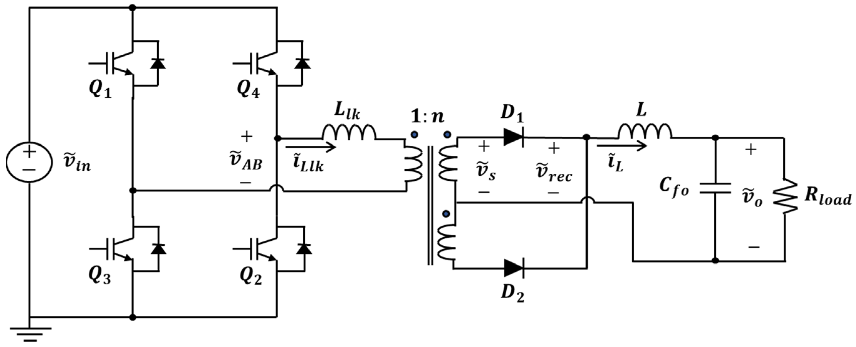
The PSFB topology (see Figure 13) combines the robustness of a full-bridge with soft-switching capabilities via phase shift control, making it suitable for high-power OBC applications [71,72].
Energy transfer is regulated by the phase shift ϕ between diagonal leg pairs:
V out = V in · N s N p · ϕ π , L lk = V in · t ZVS I pri
L V out ( 1 D ) Δ I L · f s , C Δ I L 8 f s · Δ V out
Thanks to ZVS achieved via leakage inductance L lk , switching losses are significantly reduced. However, accurate timing and dead-time control are critical to avoid shoot-through or loss of ZVS.
PSFB converters operate at fixed frequency and deliver good performance in the 6.6–22 kW range, especially in conjunction with SiC switches. Unlike LLC, they tolerate wider voltage ranges but require larger output filters due to square-wave excitation [73,74].

5.6. Dual Active Bridge (DAB) Converter

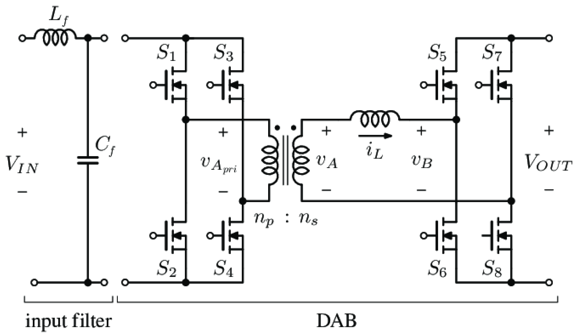
The DAB converter (see Figure 14) is a bidirectional, isolated topology enabling seamless power flow in both directions, making it ideal for V2G/V2L-capable OBCs [75,76].
Power transfer is controlled via the phase shift ϕ between the two bridges:
P = n V 1 V 2 2 π f s L · ϕ 1 ϕ π , L = n V 1 V 2 2 π f s P nom · ϕ nom 1 ϕ nom π .
A practical sizing of the output capacitor is
C o I out 8 f s Δ V out .
The DAB naturally supports ZVS/ZCS depending on load and ϕ , and its square-wave excitation concentrates EMI around f s , simplifying filtering [77,78]. It is the preferred architecture for bidirectional OBCs (e.g., 3.3–22 kW), enabling energy arbitration, V2G, and integration with battery-buffered stations. GaN and SiC devices further extend its performance at high frequency.

5.6.1. Battery Degradation Under Frequent Reverse Cycling

Although electrically well-suited for V2G, the DAB imposes frequent charge/discharge micro-cycles that can accelerate Li-ion battery degradation. Stress factors include depth of discharge (DoD), C-rate, temperature, SOC operating window, and the presence of ripple currents. A widely used lifetime metric is the Equivalent Full Cycles (EFCs):
EFC ( t ) = 1 2 Q nom 0 t | I batt ( τ ) | d τ ,
which account for both forward and reverse cycling. Partial cycles can be aggregated via rainflow counting, and the resulting degradation can be approximated as
Δ SOH i DoD i β f ( C i ) k T ( T i ) ,
with 0.3 β 0.6 , f ( C i ) increasing with C-rate, and k T ( T ) following an Arrhenius-type law. Thus, repetitive shallow V2G cycles, if uncontrolled, may lead to cumulative wear.

5.6.2. Ripple Currents and Battery Stress

In grid-connected mode, the power flow exhibits a 2 ω grid component. If the DC-link capacitance is insufficient, this appears as a current ripple on the battery:
i batt ( 2 ω ) P ac 2 V batt cos ( 2 ω grid t ) .
To limit battery ripple below 1–2% of rated current, adequate DC-link filtering or active ripple compensation is required.

5.6.3. Mitigation Strategies

DAB control strategies such as triple-phase-shift modulation minimize circulating current, while BMS coordination should constrain SOC range, C-rate, and operating temperature. To summarize, Table 6 provides recommended design and operational guidelines for minimizing battery degradation in V2G applications using DAB-based OBCs.

5.7. Comparison of DC/DC Converter Topologies

Table 7 summarizes the main characteristics of isolated DC/DC topologies, highlighting their suitability for different power levels, switching regimes, and system integration scenarios [79].
Flyback and forward converters are confined to auxiliary functions due to their limited power capability and hard-switching losses.
Push–pull offers better transformer utilization but suffers from flux imbalance sensitivity. Its practical relevance is now limited due to the availability of more robust alternatives.
Half-bridge and PSFB dominate mid-to-high power unidirectional applications. PSFB provides soft-switching over a broad load range, exploiting transformer leakage energy:
E L = 1 2 L lk I pri 2
LLC converters achieve soft-switching through resonant operation and offer high efficiency and compactness, especially at partial loads. Their frequency-dependent gain:
M ( f s ) = n 1 f r f s 2 + j · 1 Q · f r f s
allows regulation without pulse-width variation, simplifying control.
The DAB converter enables full bidirectionality with natural soft-switching. Its power flow is phase-controlled:
P = n V 1 V 2 2 π f s L · ϕ 1 ϕ π
Its symmetrical architecture, compact EMI spectrum, and compatibility with energy arbitrage functions make it the most versatile choice for high-end OBCs.
In terms of harmonic performance, hard-switched converters exhibit wideband EMI and high THD, while soft-switched (LLC, PSFB, DAB) solutions significantly reduce dv/dt and di/dt, easing compliance and reducing filter bulk.
Only resonant or soft-switched topologies fully benefit from WBG semiconductors, enabling high-frequency operation without compromising efficiency. For this reason, LLC and especially DAB are considered the most promising candidates for main-stage conversion in next-generation, high-voltage, bidirectional OBCs [80,81].

6. Power Switch Technologies in On-Board Chargers

Power semiconductor devices represent a critical enabling technology in OBC design, shaping switching behavior, thermal management, volumetric density, and ultimately system efficiency [82,83]. While traditional Si-MOSFET and IGBT technologies have historically dominated due to their maturity and cost-effectiveness, the evolution toward high-performance and compact systems is accelerating the adoption of wide-bandgap (WBG) semiconductors such as SiC and GaN [84,85].
Device choice must be closely aligned with converter topology and operating conditions. PFC stages demand ruggedness at high voltage and temperature, whereas resonant DC/DC stages benefit from ultra-low switching losses and MHz-class operation [86].

6.1. Mathematical Model for Losses

Total power loss in a switch can be approximated as
P loss = I rms 2 R on + 1 2 V ds I load ( t on + t off ) f sw
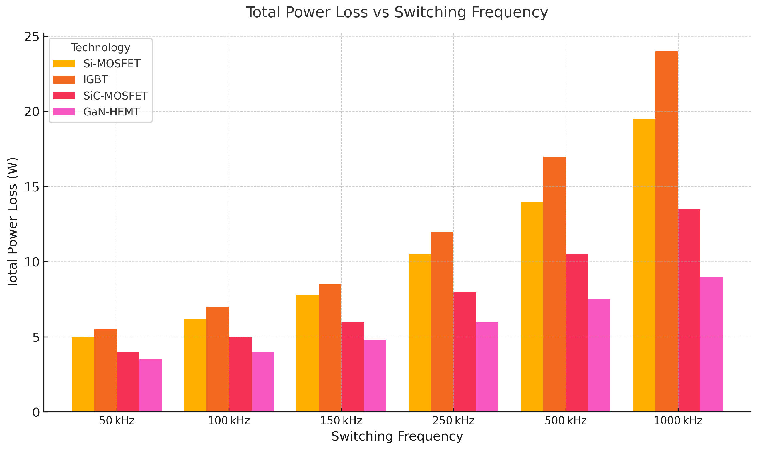
where R on is the on-resistance (or V C E ( s a t ) / I for IGBT), t on / off are the switching transition times, and f sw is the switching frequency. While Si devices suffer from increased losses with frequency due to slower transitions, WBG devices maintain low switching energy thanks to faster transitions and reduced parasitics [87].
Figure 15 illustrates this trade-off quantitatively under representative conditions (400 V, 30 A), showing how WBG devices decouple switching frequency from efficiency, thereby enabling higher power density through reduced passive component size [85,88].

6.2. Qualitative Performance Trade-Offs

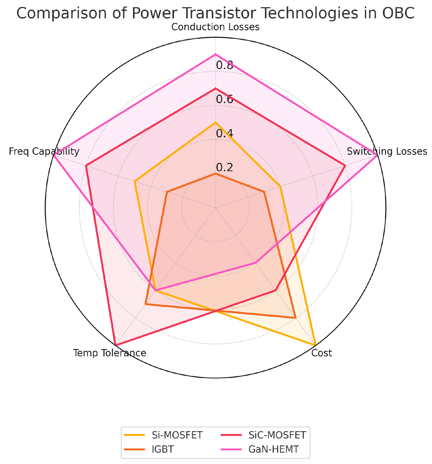
A normalized radar chart (Figure 16) offers a comparative view across key performance indicators:
  • GaN excels in switching losses and high-frequency operation (up to MHz), making it ideal for resonant converters.
  • SiC dominates in thermal capability and high-voltage endurance (up to 1.7 kV+), favored in PFC stages.
  • Si and IGBT remain suitable for cost-driven or legacy applications operating at low frequencies.

6.3. System-Level Considerations and Integration

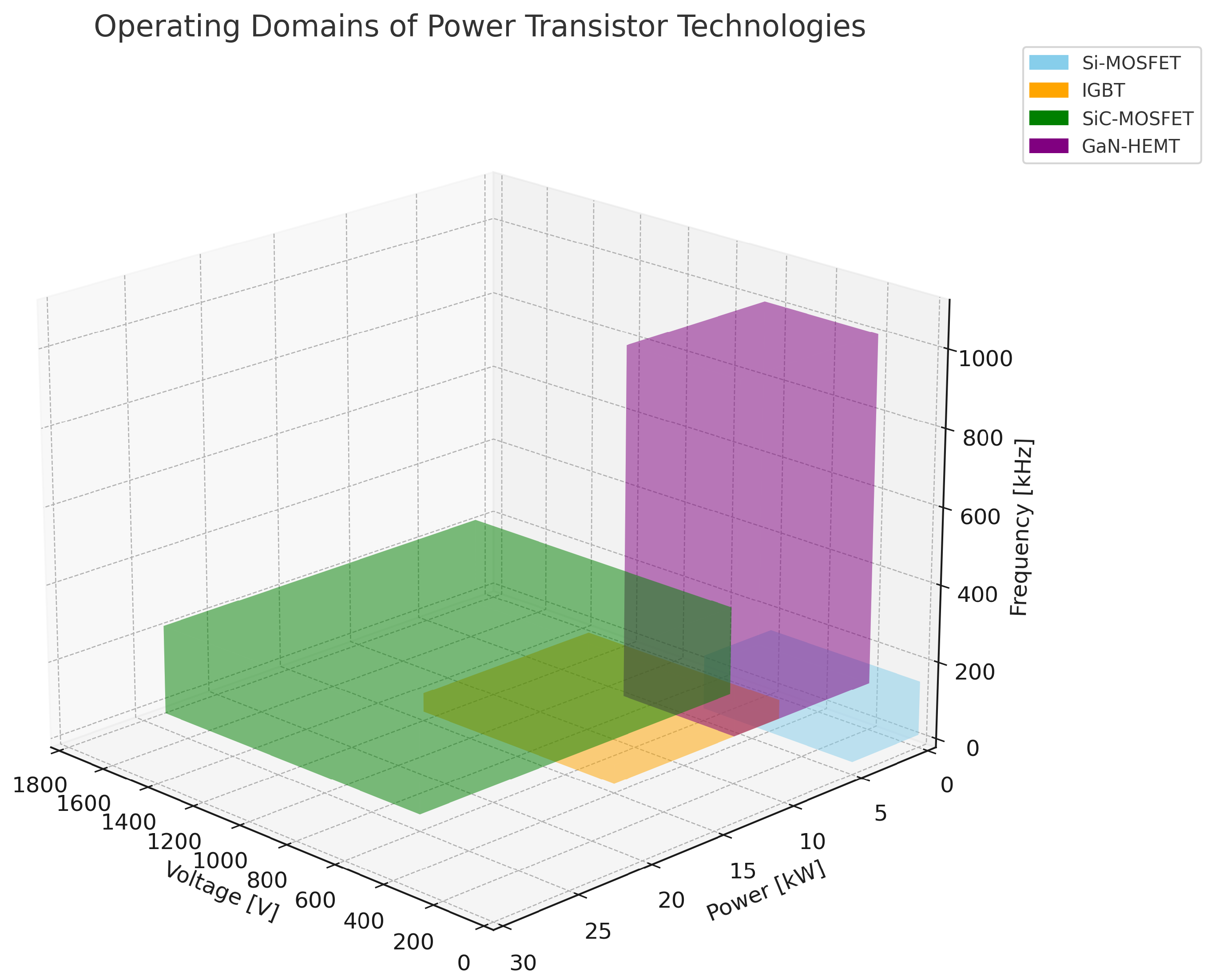
The selection of power switches is not only based on voltage and current ratings, but also tightly coupled with control bandwidth, EMI constraints, and thermal derating [89,90]. Figure 17 offers a systemic mapping across voltage, power, and frequency domains.
  • GaN: High frequency (up to MHz), low-to-mid voltage (up to 650 V), power range up to approx. 10 kW.
  • SiC: Medium-to-high frequency (up to 500 kHz), high voltage (up to 1700 V), power up to over 100 kW.
  • IGBT: Low frequency (below 50 kHz), mid-to-high voltage, power above 100 kW.
  • Si: Cost-effective, low-power (below 1 kW), low-frequency solutions.
The plot confirms that no single technology dominates across all axes. GaN is unmatched for MHz-class converters (e.g., LLC), while SiC is ideal for totem-pole or interleaved PFC stages under thermal and voltage stress [85].
Integration challenges differ significantly: GaN requires tight layout optimization to minimize parasitics and ensure thermal management at high densities, whereas SiC offers more tolerance in gate driving and voltage margin but at higher cost [87,91].

6.4. Summary Table

To complement the graphical insights, Table 8 provides a comparative summary of the main semiconductor technologies considered in OBC applications. Key parameters include bandgap, voltage capability, conduction and switching performance, thermal properties, and integration aspects such as gate drive complexity and cost.
While traditional silicon (Si) and IGBT technologies remain relevant in low-frequency or cost-constrained designs, wide-bandgap devices clearly offer superior performance across most critical metrics. SiC MOSFETs combine high voltage ratings with excellent thermal conductivity and relatively simple gate driving, making them ideal for high-power PFC or DC/DC stages. GaN HEMTs, on the other hand, are optimized for fast switching at high frequencies, offering minimal dynamic losses and enabling high-density resonant converter designs [85,86].
The table emphasizes how the selection of the optimal technology is inherently multi-dimensional: designers must balance electrical performance, thermal limits, EMI constraints, and economic factors, especially in multi-stage OBC architectures [83,85,88].

6.5. Trends and Outlook

Recent research confirms that the design paradigm is shifting: from discrete component optimization toward holistic system-level performance [82,83,85]. For instance, recent AMPC-based control strategies explicitly exploit WBG advantages to reduce switching losses and stress [92], while model-based and AI-enhanced diagnostics enable proactive reliability monitoring of WBG-based systems [89,93].
As qualification standards evolve and costs fall, WBG devices are expected to become the default choice for all high-performance OBC stages, including both primary and auxiliary converters [84,85,88].

7. Transformers in Automotive Charging Systems

Transformers are essential components in isolated converter stages, enabling voltage adaptation and galvanic decoupling across distinct energy domains. In OBC architectures, they determine not only electrical behavior but also impact system volume, efficiency, EMI, and thermal performance [94,95,96].
Galvanic isolation between the grid and the high-voltage battery is a fundamental requirement, mandated by safety standards such as IEC 61851 and ISO 6469. This isolation is typically provided by a high-frequency transformer integrated into the OBC.
The position and function of the transformer depend on the power conversion architecture. In two-stage configurations, it is part of the downstream isolated DC/DC stage (e.g., LLC, PSFB, DAB), following a PFC stage. In single-stage systems, the transformer may directly interface with the rectified AC voltage [97].
In V2G-ready or fast-charging topologies, bidirectional isolated stages also rely on transformers to handle reverse power transfer and ensure consistent insulation under dynamic load conditions [96,98].
In all cases, the transformer is not a passive link but a critical element for enabling compact, efficient, and standards-compliant conversion [99,100].

7.1. Functional Requirements

The transformer must simultaneously ensure:
  • Galvanic isolation between input and output domains;
  • Voltage scaling across a wide range (e.g., 300–900 V battery vs. 230–400 V bus);
  • EMI suppression via coupling geometry and winding symmetry;
  • Thermal robustness under high-frequency, high-power conditions.
To achieve these goals, transformers are typically operated between 100 and 500 kHz and use ferrite materials with low core losses and high permeability stability [101].

7.2. Ideal Model and Deviations

In ideal conditions, the transformer windings relate via the time derivative of mutual flux ϕ ( t ) :
v 1 ( t ) = N 1 d ϕ ( t ) d t , v 2 ( t ) = N 2 d ϕ ( t ) d t
yielding
v 2 ( t ) v 1 ( t ) = N 2 N 1 = n , i 1 ( t ) = 1 n i 2 ( t )
However, practical transformers exhibit non-idealities that significantly affect system behavior, especially under high-frequency operation.
The equivalent circuit (referred to primary) includes
  • Winding resistances R 1 , R 2 ;
  • Leakage inductances L σ 1 , L σ 2 ;
  • Magnetizing inductance L m ;
  • Core loss resistance R fe .
The voltage equation in Laplace domain:
v 1 ( s ) = ( R 1 + s L σ 1 ) i 1 ( s ) + 1 s L m 1 R fe i m ( s ) + v 2 ( s )
with reflected secondary impedance:
v 2 ( s ) = N 1 N 2 2 R 2 + s L σ 2 + Z load i 2 ( s )
The peak flux density constraint can be calculated as
B peak = V ac · D · T s N · A e
Maintaining B peak < B sat is critical to avoid core saturation and overheating. This condition governs the minimum required number of turns at a given voltage and frequency [102].

7.3. Thermal Interactions and Loss Modeling

Transformer losses consist of
  • Copper losses:
    P Cu = I rms 2 R winding
  • Core losses (for ferrites):
    P core ( f , B ) = k h f B α + k e f 2 B 2
    where k h , k e are material constants, and α [ 1.6 , 2.2 ] . These losses grow steeply with frequency and B.
High-frequency operation reduces magnetic volume but increases AC resistance due to skin and proximity effects. Litz wire or planar windings are typically used to mitigate this [94,95].
Thermal rise estimation:
Δ T = R th · ( P Cu + P core )
As temperature increases, core permeability degrades, L m drops, and B sat reduces. These effects feed back into switching behavior, voltage gain, and ZVS boundaries.
Transformer aging is governed by thermal stress on insulation, modeled by
L ( T ) = L 0 · exp E a k 1 T 1 T 0
where L ( T ) is expected life, E a activation energy, and k Boltzmann constant.
In charging stations with large EV demand, thermal stress and reactive power flow significantly influence transformer aging and energy losses at the grid interface [103].

7.3.1. Frequency-Dependent Efficiency Outlook

To justify the adopted operating bands, Table 9 reports transformer-only efficiency estimates versus switching frequency for typical OBC architectures. Figures refer to well-optimized ferrite cores (automotive-grade), litz or planar windings, B peak 0.10 0.18 T, coolant-cooled packaging, and 3.3–22 kW power. As frequency rises, core loss ( f B α and f 2 B 2 terms) and AC copper loss (skin/proximity) increase, so transformer efficiency gently decreases while volume and filter size shrink. These ranges help select frequency targets consistent with efficiency, power density, and EMI constraints discussed in Section Figure 12 and Table 10.
A compact sizing rule for transformer efficiency is
η xfmr ( f , B , T ) 1 P core ( f , B , T ) + P Cu ( f , T ) + P misc P out .
For a fixed power level, moving from 100 kHz to 300–400 kHz typically trades a few tenths of a percent of transformer efficiency for noticeable reductions in magnetic volume and external filtering. The frequency bands in Table 9 therefore align with the architectural choices in Table 10: LLC/PSFB favor 100–250 kHz for peak efficiency, while high-density single-stage resonant or planar-centric designs justify 250–500 kHz when volume and integration dominate.

7.3.2. Impact of Vibrations in Automotive Environments

In addition to thermal and electrical stresses, transformers and magnetic components in OBCs are continuously exposed to mechanical vibrations and shocks typical of the automotive environment. Long-term vibration can lead to insulation degradation, loosening of windings, cracking of potting or encapsulation materials, and solder joint fatigue at the terminations, ultimately reducing lifetime and reliability. Typical failure mechanisms include partial discharge initiation at micro-cracks, resonance-induced displacement of winding layers, and progressive delamination of planar structures.
Automotive qualification standards such as ISO 16750 and IEC 60068 [104] prescribe random vibration, sinusoidal sweep, and mechanical shock tests to verify robustness of power electronic assemblies under real vehicle conditions. To meet these requirements, magnetics in OBCs are generally impregnated or potted with vibration-resistant resins, employ reinforced mechanical fixation of cores and bobbins, and use flexible interconnections to reduce stress concentration on solder joints. For planar transformers, laminated PCB stacks must be designed with adequate compliance to avoid copper trace cracking under repeated mechanical cycling.
Overall, vibration robustness is as critical as thermal management in determining the effective lifetime of transformers in automotive OBCs. A comprehensive design approach therefore combines magneto-thermal modeling with structural reliability assessment, ensuring that high-frequency magnetics maintain both electrical performance and mechanical integrity across the entire automotive vibration spectrum.

7.4. Design Evolution and Integration Trends

Modern designs increasingly adopt planar transformers for automated manufacturing, reduced profile, and predictable parasitics [94,95].
Emerging approaches include integrated magnetics—merging filtering and isolation functions—to reduce volume and improve coupling [99,105].
Designers now employ magneto-thermal co-simulation tools to predict 3D loss distribution, hot spots, and EMI behavior under real driving profiles. This is especially relevant for underbody or thermally constrained packaging [106].

7.5. Architectural Comparison

The transformer parameters—turns ratio, leakage, core shape—must be co-optimized with control strategy (e.g., ZVS point, phase shift, gain regulation), especially in resonant or bidirectional systems [96,101,102].
For example, in LLC, the transformer defines the resonant frequency and affects soft-switching; in DAB, leakage inductance is exploited to enable phase-shift modulation. In auxiliary converters, thermal derating is often transformer-limited.

7.6. Final Remarks

The transformer is a multi-domain component at the intersection of magnetics, thermal, mechanical, and control design. Its behavior shapes the performance limits of every isolated converter stage in OBCs [100].
Future advancements will hinge on better integration (planar, multi-core), predictive modeling (co-simulation), and material science (nanocrystalline cores, thermal interfaces), enabling higher power density and bidirectionality in electrified powertrains [98,107].

8. Battery Pack

8.1. Cell Technology and Chemistry

Cell chemistry (cathode/anode/electrolyte system) and cell format (mechanical form factor) are two largely orthogonal design dimensions. While certain pairings are common in current automotive products due to supply chain maturity and integration preferences, there is no one-to-one mapping between chemistry and format. For example, LFP is often produced in prismatic format for high-volume traction packs, but LFP pouch and cylindrical variants exist; pouch cells often use NMC/NCA; and modern cylindrical cells (e.g., 46xx) use NMC or NCA. The final choice results from multi-objective optimization across safety, energy/power density, thermal pathway, structural constraints, cost, and manufacturability.

8.1.1. Chemistry Overview (Automotive Li-Ion)

The most widely adopted chemistries for traction packs are NMC, NCA, and LFP. At cell level, they differ in nominal voltage, energy density, abuse tolerance, degradation mechanisms, and fast-charging acceptance:
  • NMC (LiNiMnCoO2): Balanced energy/power with tunable Ni/Mn/Co ratios; wide deployment across formats (prismatic, pouch, cylindrical). Good energy density, moderate abuse tolerance, fast-charging limited by Li plating risk at low temperature/high SOC.
  • NCA (LiNiCoAlO2): Among the highest gravimetric energy; widely used in cylindrical and pouch. Higher thermal sensitivity and stricter fast-charge management (temperature/SOC control) are typically required to mitigate aging and safety risk.
  • LFP (LiFePO4): Lower nominal voltage and energy density but markedly higher thermal/chemical stability, flat OCV curve, and long cycle life; prevalent in prismatic format for high-volume packs, with growing adoption in alternative formats. Tolerant to high C-rate at moderate temperatures when appropriately cooled.

8.1.2. Format Overview (Mechanical/Thermal Integration)

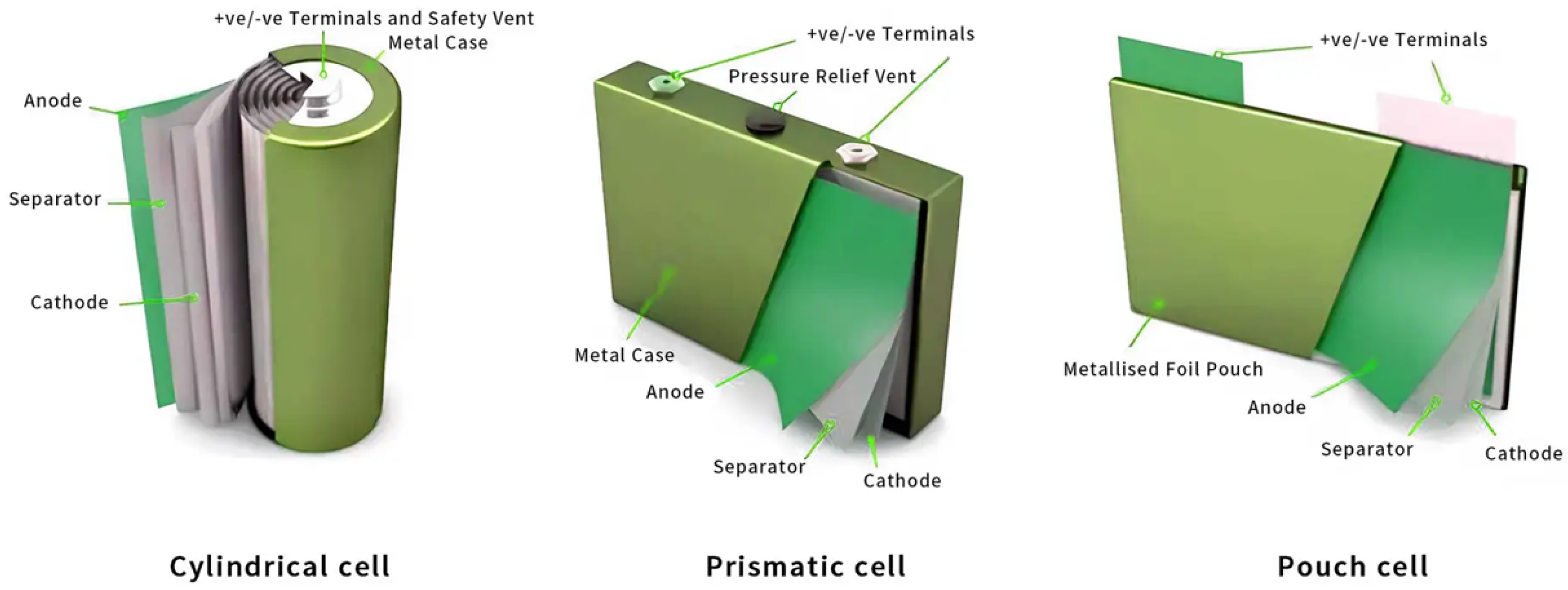
Format selection (see Figure 18) primarily affects volumetric packing, heat paths, structural behavior, and manufacturing throughput:
  • Cylindrical: Robust “jelly-roll”, excellent mechanical integrity and venting control, high line-speed manufacturing; historically lower packing factor due to interstitial voids, mitigated by large-format designs (e.g., 46xx) and tabless current collectors that reduce ohmic gradients and promote fast charge.
  • Prismatic: High volumetric efficiency, flat interfaces for baseplate/side cooling, straightforward series/parallel busbar integration; requires attention to through-plane thermal gradients and shell expansion management.
  • Pouch: Highest gravimetric efficiency and short thermal path; requires compressive fixture to control swelling and to maintain interfacial contact; mechanical protection and gas management are critical for abuse robustness.

8.1.3. Chemistry Metrics (Typical Cell-Level Ranges)

Table 11 reports indicative cell-level metrics used in automotive design. Values are representative and depend on supplier and generation.

8.1.4. Format Attributes (Integration-Centric)

Table 12 summarizes format-driven attributes relevant to pack integration, cooling, and durability.

8.1.5. Chemistry–Format Interplay Without Conflation

Because chemistry governs electrochemical performance and safety margins, while format governs packaging and heat removal, OEMs typically co-optimize both (see Figure 19). Illustrative (non-exclusive) patterns observed in production are (i) LFP—prismatic for cost, safety, and cycle life in high-volume platforms; (ii) NMC/NCA—cylindrical, where manufacturing scale and mechanical robustness are prioritized (including large-format 46xx); (iii) NMC/NCA—a pouch in architectures that exploit compact stacking and aggressive cooling. Deviations from these patterns are common and growing as supply chains diversify.

8.1.6. From Cell to Pack: Implications for OBC Design

Pack voltage V pack results from the series string ( N s ) and parallel grouping ( N p ), and determines the OBC output range. Chemistries with lower nominal cell voltage (e.g., LFP) typically require higher N s for a given V pack , which affects insulation and derating margins. Format determines feasible heatsink interfaces and sensor placement, influencing fast-charge acceptance and ripple limits at the OBC–battery boundary. Chemistries with flatter OCV (e.g., LFP) call for higher-resolution BMS estimation (impedance/thermal models) to maintain accurate SOC/SOH under fast charging.
The main symbols and parameters used throughout the discussion of battery packs are summarized in Table 13. This nomenclature includes quantities related to the electrical configuration of the pack, such as the number of series and parallel cells, as well as key performance indicators like nominal capacity, C-rate, state of charge, and state of health, providing a clear reference for the terminology adopted in the following sections.

8.1.7. Pack-Level Ranges (Indicative)

Typical traction packs span 320–1000 V depending on N s and chemistry. High-voltage architectures (700–1000 V) reduce current for a given power, easing cable/heatsink sizing and enabling higher fast-charge power, at the cost of stricter insulation and EMC constraints. Cell/format choices should therefore be co-designed with OBC output stage, isolation ratings, thermal management, and BMS estimation fidelity.

8.2. Battery Pack Architecture and OBC Interface

The architecture of the battery pack influences voltage scalability, integration effort, thermal performance, and the design constraints imposed on the OBC (see Table 14). Beyond energy storage, the pack serves as an electromechanical system tightly coupled to vehicle layout and power electronics [108,109].
The arrangement of cells into modules and packs defines the nominal voltage range, energy capacity, and the OBC’s voltage conversion and insulation requirements. High-voltage systems (700–1000 V) are increasingly common in new platforms to support ultra-fast charging, whereas legacy systems remain below 400 V [110,111].
Mechanical integration (e.g., floor-mounted vs. tunnel-mounted), crashworthiness, and cooling strategy (air, liquid, immersion) affect not only thermal balance but also EMI and system safety [112,113].
Electrically, the interface with the OBC must account for
  • Insulation requirements (e.g., 1–2.5 kV isolation levels);
  • Ripple current tolerance and filter sizing;
  • Transient overshoot and reverse recovery behavior;
  • Pack inductance and loop parasitics.
Each of these elements impacts OBC topology choice (e.g., DAB vs. PSFB), gate driving constraints, and protection mechanisms.
From an integration standpoint, OBC designs must consider whether bidirectional charging is supported, as this affects not only converter topology but also monitoring requirements (e.g., isolation resistance under discharge) [109,114].
In V2G-ready platforms, bidirectional power flow requires real-time monitoring of insulation, temperature, and cell health across all modes of operation. This pushes the system toward higher-resolution sensing, dual-bus communication, and predictive diagnostic models co-designed with the pack electronics [115,116].
The convergence toward high-voltage packs and faster charge cycles is progressively shifting the OBC–battery interface from a passive load model to an active, dynamically managed boundary [117].

8.2.1. Filter Examples to Meet Battery Ripple Specifications

In practice, ripple constraints at the OBC–battery boundary are set by two distinct phenomena: (i) the low-frequency pulsation at 2 ω grid (due to single-phase AC instantaneous power) and (ii) the high-frequency component at the converter switching frequency f s . Each requires different mitigation strategies.
(A)
Low-frequency (2 ω ) ripple decoupling
For unity power factor operation, the instantaneous AC-side power contains a 2 ω grid component with an amplitude equal to the average transferred power P dc . If the DC-link energy buffer is insufficient, part of this oscillation appears as low-frequency current ripple at the battery. To limit the relative peak-to-peak voltage ripple on the DC bus within Δ V rel , pp , the minimum capacitance is
C min P dc ω grid V dc 2 Δ V rel , pp .
Alternatively, an Active Ripple Port (ARP) based on a supercapacitor and bidirectional converter can absorb the oscillating energy selectively, drastically reducing the required high-voltage DC-link capacitance.
(B)
High-frequency ripple (switching) shaping
On the battery side, a passive LC filter (series L batt and shunt C batt ) attenuates switching ripple. With
f c = 1 2 π L batt C batt ,
a practical design guideline is to place the cutoff frequency in the range f s / 10 to f s / 20 , achieving an attenuation of approximately ( f c / f s ) 2 at the switching frequency. The series inductance can be estimated from the ripple current specification:
L batt V ac , eff ( f s ) 2 π f s Δ I batt , pp or L batt = 1 ( 2 π f c ) 2 C batt ,
where V ac , eff ( f s ) is the residual AC component at the converter output.

8.2.2. Worked Example 1 (6.6 kW, 400 V, 50 Hz): 2 ω Decoupling

With P dc = 6.6 kW, V dc = 400 V, f grid = 50 Hz, and Δ V rel , pp = 0.5 % :
C min 6600 ( 2 π · 50 ) · 400 2 · 0.005 26 mF .
This capacitance at 400 V is impractically large for a compact OBC. Using an ARP at 48 V, the oscillation energy is E amp = P dc / ( 2 ω ) 10.5 J. Allowing a 5% ripple at 48 V ( Δ V 1.2 V), the required capacitance is C ARP 0.18 F (180 mF), which is feasible with automotive supercapacitors.

8.2.3. Worked Example 2 (6.6 kW, 400 V, f s = 150  kHz): HF LC Filter

With rated battery current I rated = P / V = 16.5 A and a target ripple of 1% ( Δ I batt , pp 0.165 A), set f c = f s / 10 = 15 kHz and C batt = 100 μ F. Then,
L batt = 1 ( 2 π · 15   ×   10 3 ) 2   ·   100   ×   10 6 1.1 μ H .
The resulting second-order attenuation is ( f c / f s ) 2 = ( 0.1 ) 2 = 0.01 , which is sufficient to meet the ≤1–2% current ripple requirement.

8.2.4. LCL Filters and Damping

For stronger attenuation or interaction with pack parasitics, an LCL filter can be used. Splitting the inductance ( L 1 on the converter side, L 2 near the battery) plus a shunt capacitor C provides improved filtering. A damping resistor R d (series with C, or parallel RC) is necessary to control resonance ( Q 0.7 ). The design is as follows:
f c 1 1 2 π L 1 C , f c 2 1 2 π L 2 C .
Table 15 summarizes the main strategies adopted for ripple mitigation on the battery side of onboard chargers. Different options are compared in terms of typical application range, design considerations, and main advantages and drawbacks. Passive LC filters represent a simple and cost-effective solution for high-frequency components, while LCL filters improve attenuation at the expense of higher design complexity. Active ripple ports, instead, target low-frequency oscillations and enable ancillary functionalities such as V2G, whereas hybrid approaches combine passive and active stages to achieve superior performance in high-power-density systems.

8.2.5. Integration Notes

Filter effectiveness strongly depends on PCB layout (minimizing ESL/ESR), component placement (inductors close to the pack connection), and interaction with OBC control loops. In V2G-ready platforms, ARP or hybrid approaches are increasingly used to meet stringent ripple specifications without resorting to massive high-voltage capacitors.

8.3. Battery Management System: Functions and Control Integration

The BMS is the functional and supervisory interface between the battery pack and all surrounding subsystems, including the OBC. Its role extends from safety assurance to dynamic control of charge, discharge, thermal behavior, and health estimation [109,115].
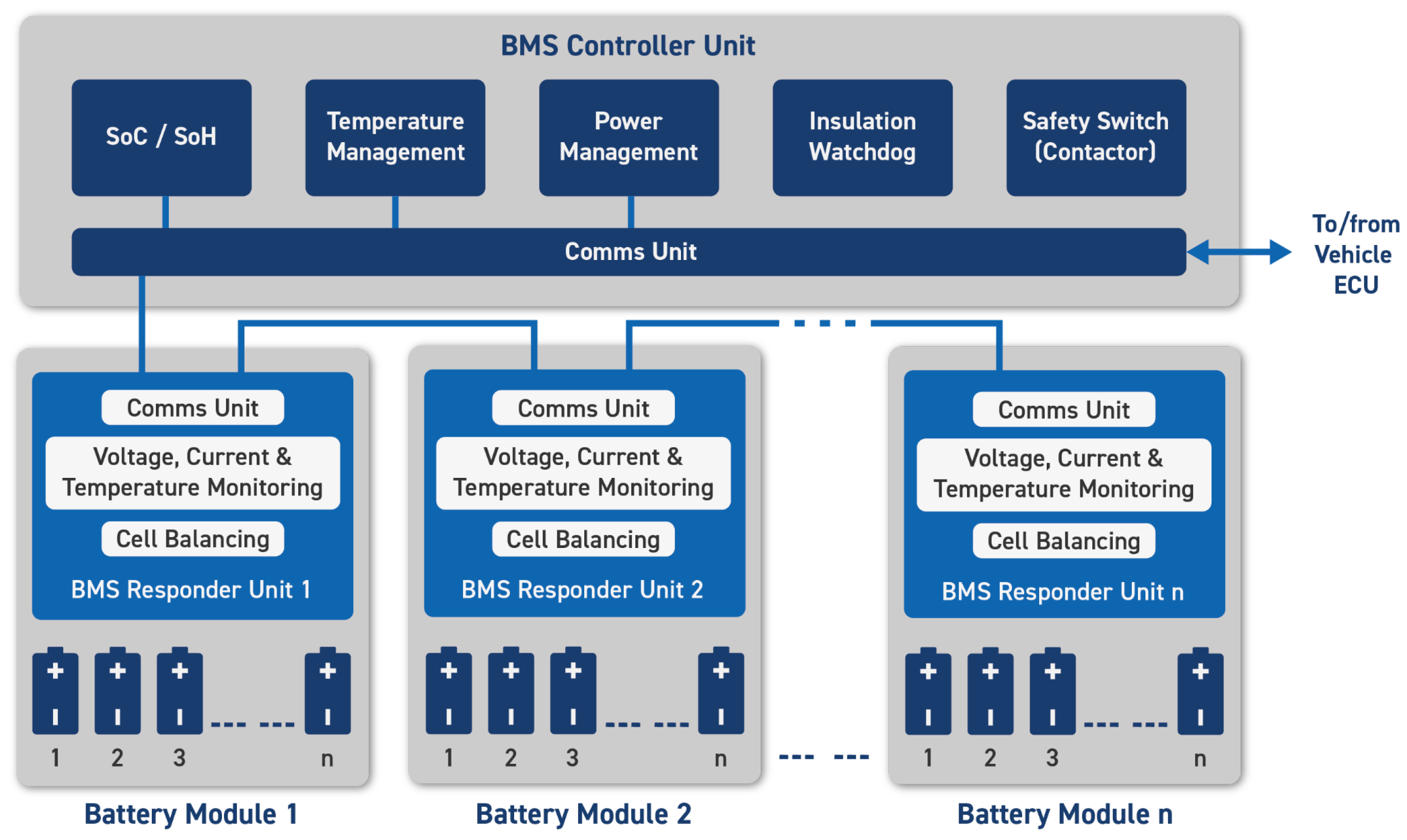
Its architecture is typically distributed, with multiple monitoring modules interfaced to a central controller that manages diagnostics, data communication, balancing, and protection (see Figure 20).
1.
State Estimation (SOC, SOH, SOT)
The BMS estimates SOC, SOH, and temperature using hybrid models. SOC is typically based on coulomb counting with voltage correction:
SOC ( t ) = SOC ( t 0 ) 1 Q nom t 0 t I ( τ ) d τ + Δ corr ( V term , T )
SOH is often estimated via
SOH Q ( t ) = Q eff ( t ) Q nom , SOH R ( t ) = R nom R int ( t )
These estimates are passed to the OBC for dynamic adjustment of current and voltage limits, especially in fast-charging and derating scenarios [115,118].
2.
Charge and Discharge Control
The BMS defines safe current and voltage bounds, adjusting them in real-time based on temperature and SOC:
I chg , max ( T , S O C ) = I 0 · e α T ( T T ref ) 2 α S ( S O C S O C opt ) 2
These limits are transmitted to the OBC via real-time communication (e.g., CAN-FD, ISO 15118), ensuring safe operation even under dynamic or bidirectional load conditions [109].
3.
Power Management and Thermal Control
The BMS allocates power internally, manages cooling loops, and initiates derating:
C th · d T d t = P loss h A ( T T cool )
Derating strategies are tightly coupled to BMS–OBC coordination and may involve preemptive current reduction under thermal stress [108,113].
4.
Cell Monitoring and Balancing
Balancing is achieved via either passive bleeding or active redistribution. A model-based formulation:
min { u i } i = 1 n ( S O C i S O C ¯ ) 2 s . t . u i { 0 , 1 }
Maintaining balanced cells improves usable capacity and reduces charge time mismatches, especially critical in V2G cycles with partial SOC windows [111,119].
5.
Fault Detection and Isolation
The BMS performs fault monitoring, including
  • Sensor drift;
  • Isolation loss;
  • Overtemperature or overvoltage;
  • Short circuits.
Insulation integrity is checked via a watchdog circuit:
R iso R min 1 M Ω
This is particularly important during reverse power flow or high-voltage discharge events [109,114].
6.
Communication and Control Integration
Robust communication with the OBC and vehicle ECU is essential. Protocols must support low latency, redundancy, and high update rates in fast-charging or bidirectional scenarios [109,116].
In next-generation architectures, the BMS becomes a dynamic participant in charging optimization, V2G scheduling, and real-time predictive health management (as schematically represented in Figure 21). Its integration with the OBC is no longer static but part of a closed control loop [116,119].

9. Commercial Aspects and Trends

The industrial ecosystem for automotive charging systems is organized in a tiered structure, reflecting the vertical integration of technology from materials to vehicle-level deployment. Each tier contributes critical elements, from functional converters to semiconductor devices and base materials [120]. Tier 1 suppliers provide fully integrated systems to OEMs, including OBCs, DC/DC converters, and high-voltage power modules. These solutions are designed for specific vehicle platforms and must comply with stringent standards in safety, EMI, thermal performance, and reliability (see Table 16). Design differentiation often resides in architectural choices (e.g., PFC topology, DC/DC converter type), packaging strategies (e.g., integration with inverter), and WBG adoption.
Architectural patterns among Tier 1 systems show convergence toward bridgeless totem-pole PFC stages and resonant LLC or PSFB topologies, especially when high power density and efficiency are key targets. GaN and SiC devices are widely adopted depending on power level and cost constraints [121,122]. Examples include the following:
  • Hyundai Ioniq 5: OBC by Hyundai Mobis with totem-pole PFC and LLC DC/DC, operating at high frequency to minimize passive size.
  • Porsche Taycan: Bosch system combining interleaved totem-pole PFC and PSFB with ZVS control, based on SiC switches.
  • Fiat 500e: Marelli OBC using a bridgeless PFC with LLC converter, optimized for cost and compactness at 400 V.
These commercial implementations confirm the viability of the high-frequency architectures analyzed in Section 3 and Section 5, where soft-switching and WBG devices enable performance optimization at system level. Integration with traction inverter and auxiliary DC/DC modules is increasingly pursued to reduce volume, improve thermal synergy, and enable shared gate driving or filtering [123].

9.1. Tier 2: Semiconductors, Magnetics, and Control ICs

Tier 2 suppliers enable the functionality and efficiency of Tier 1 systems by delivering critical building blocks such as power devices, controllers, drivers, and magnetic components. These subsystems must meet automotive qualification standards and support lifetime targets under thermal and electrical stress (see Table 17). The success of WBG-based OBC architectures depends on the availability of fast-switching, low-parasitic power modules and dedicated gate drivers capable of managing dv/dt > 30 kV/ μ s without triggering false events [124]. For example, CoolSiC and similar SiC MOSFET modules offer reduced RDS(on) and increased avalanche robustness, while GaN-based ICs from ST and TI integrate gate control and protection features in compact footprints. Magnetic components (chokes, transformers, EMI filters) are also increasingly co-designed with converter topology. Planar magnetics optimized for LLC or DAB are key to achieving low-profile, high-frequency operation in the 200–500 kHz range [123].
The synergy between power stage, control IC, and magnetic design is now critical: manufacturers such as Würth Elektronik provide not only catalog components but also reference designs adapted to specific converter configurations [125]. Tier 2 suppliers are thus instrumental in enabling the adoption of soft-switching architectures and high-density integration, especially when power stages are co-packaged or embedded in multi-function modules.

9.2. Tier 3: Materials and Passive Component Suppliers

Tier 3 vendors supply the materials and passive elements that define the thermal, electrical, and reliability boundaries of the entire power conversion system. Their products are foundational but often less visible in the final system (see Table 18).
The performance and reliability of magnetics, PCBs, and power modules depend critically on Tier 3 materials. For instance, litz wire with precise strand geometry enables efficient operation under skin effect, while thermally conductive adhesives ensure low θ J A in compact power stages [126]. In high-power OBCs, thermal interface management is a major design constraint: poor dissipation at the module baseplate can negate the benefits of SiC or GaN efficiency. Material-grade selection becomes a co-design parameter. Furthermore, the availability of stable and automotive-certified insulation systems (e.g., from Sumitomo or Dupont) is necessary for long-term compliance with isolation requirements at elevated switching frequencies [127].

9.3. System-Level Outlook

The co-evolution of Tier 1, 2, and 3 suppliers reflects a shift from discrete design to platform-level integration. Advances in wide-bandgap devices, planar magnetics, and thermally optimized materials are converging to enable new levels of power density and bidirectional capability [120,128,129]. From a system perspective, the most successful commercial OBCs are not defined by individual components, but by their co-optimization: SiC or GaN switches, soft-switched topologies (LLC, PSFB, DAB), compact magnetics, and real-time BMS coordination. Future trends include multi-output and multi-port chargers, integrated traction/OBC stages, and V2X-aware firmware stacks. Tier 1 suppliers are already incorporating such features, while Tier 2 and Tier 3 are aligning their roadmaps accordingly [122,130]. In addition, economic and environmental perspectives are shaping product lifecycles: second-life battery integration, end-of-life recycling, and sustainability regulations are now influencing system design choices [131,132]. The alignment across the supply chain will be essential for achieving automotive-grade reliability, functional safety, and energy efficiency under the increasing demands of electrified mobility [124,128].

10. Conclusions and Future Perspectives

This article has presented a comprehensive review of the state-of-the-art in battery charging systems for electrified vehicles, covering system architecture, power conversion topologies, semiconductor devices, transformer design, battery interface, BMS functionality, and commercial implementations across the supply chain. From the AC grid to the battery pack, each functional block imposes specific design constraints—electrical, thermal, spatial, and regulatory—that must be jointly addressed through coordinated topology selection, control strategy, and component integration. The emergence of soft-switching, high-frequency architectures (LLC, PSFB, DAB) and the increasing adoption of wide-bandgap devices (SiC, GaN) are reshaping converter design practices, enabling new levels of power density and efficiency. Planar magnetics and advanced control platforms further support this transition, while BMS coordination becomes essential for optimizing charge profiles, health estimation, and V2G interaction. Commercial solutions confirm the viability of these technological directions, with production-grade OBCs already integrating high-frequency stages, resonant converters, and compact magnetics. The vertical integration across Tier 1–3 suppliers plays a decisive role in enabling scalable, reliable, and standards-compliant systems. Future developments will likely revolve around the following directions:
  • Multi-functional power stages, combining traction, charging, and auxiliary conversion in a unified architecture;
  • Bidirectional and grid-interactive chargers, with dynamic control, insulation monitoring, and active participation in grid services [123,128];
  • Digital twin and predictive models for battery-pack-aware charging, real-time diagnostics, and lifetime optimization [129];
  • Advanced materials and packaging, including embedded magnetics, thermal composites, and co-encapsulated modules;
  • Cybersecure and over-the-air upgradable platforms, aligned with evolving V2X standards and functional safety requirements.
As electrified mobility scales from passenger to commercial and heavy-duty applications, OBC systems will need to deliver not only higher performance but also greater modularity, resilience, and intelligence. The ability to co-design hardware, firmware, and interface protocols will be central to achieving this evolution. In this context, the OBC is no longer a standalone subsystem but a key node in the energy and information flow of next-generation electric vehicles.

Author Contributions

Conceptualization, P.D.; Methodology, P.D., S.S., S.C. and O.H.; Investigation, P.D., S.S., S.C. and O.H.; Writing—original draft, P.D.; Writing—review and editing, P.D., S.S., S.C. and O.H.; Visualization, P.D., S.C.; Supervision, S.S. and O.H.; Project administration, S.S. All authors have read and agreed to the published version of the manuscript.

Funding

The work has been partially supported by National Centre for HPC, Big Data and Quantum Computing, Spoke 6, CUP B83C22002940006, Multiscale modelling & Engineering applications; and by the ECSEL JU project Hiefficient n. 101007281 (EU ECSEL-2020-2-RIA call); and by MIUR FoReLab Project, Dipartimenti di Eccellenza.

Data Availability Statement

No new data were generated or analyzed in this study. All information presented is based on previously published sources, which are appropriately cited throughout the manuscript.

Conflicts of Interest

The authors declare no conflicts of interest.

Abbreviations

ACAlternating Current
AFEActive Front-End
BMSBattery Management System
CCMContinuous Conduction Mode
DCDirect Current
DCMDiscontinuous Conduction Mode
DABDual Active Bridge
EMCElectromagnetic Compatibility
EMIElectromagnetic Interference
EVElectric Vehicle
GaNGallium Nitride
IGBTInsulated Gate Bipolar Transistor
LLCInductor–Inductor–Capacitor (resonant converter)
MOSFETMetal–Oxide–Semiconductor Field-Effect Transistor
NCANickel Cobalt Aluminum
NMCNickel Manganese Cobalt
OBCOn-Board Charger
OEMOriginal Equipment Manufacturer
PCBPrinted Circuit Board
PCCPoint of Common Coupling
PDUPower Distribution Unit
PFCPower Factor Correction
PLLPhase-Locked Loop
PSFBPhase-Shifted Full Bridge
PWMPulse Width Modulation
RMSRoot Mean Square
SiSilicon
SiCSilicon Carbide
SOC        State of Charge
SOHState of Health
SOTState of Temperature
THDTotal Harmonic Distortion
UPSUninterruptible Power Supply
V2GVehicle-to-Grid
V2LVehicle-to-Load
V2HVehicle-to-Home
VOCOpen Circuit Voltage
WBGWide Bandgap
ZCSZero Current Switching
ZVSZero Voltage Switching

References

  1. Shahjalal, M.; Shams, T.; Tasnim, M.N.; Ahmed, M.R.; Ahsan, M.; Haider, J. A critical review on charging technologies of electric vehicles. Energies 2022, 15, 8239. [Google Scholar] [CrossRef]
  2. Tejeida-Padilla, R.; Berdeja-Rocha, E.M.; Badillo-Piña, I.; Pérez-Matamoros, Z.; Amador-Santiago, J.E. A Comprehensive Review of Electric Charging Stations with a Systemic Approach. World Electr. Veh. J. 2024, 15, 571. [Google Scholar] [CrossRef]
  3. Dini, P.; Saponara, S.; Colicelli, A. Overview on battery charging systems for electric vehicles. Electronics 2023, 12, 4295. [Google Scholar] [CrossRef]
  4. Rachid, A.; El Fadil, H.; Gaouzi, K.; Rachid, K.; Lassioui, A.; El Idrissi, Z.; Koundi, M. Electric vehicle charging systems: Comprehensive review. Energies 2022, 16, 255. [Google Scholar] [CrossRef]
  5. Nkembi, A.A.; Cova, P.; Sacchi, E.; Coraggioso, E.; Delmonte, N. A comprehensive review of power converters for E-mobility. Energies 2023, 16, 1888. [Google Scholar] [CrossRef]
  6. Nasr Esfahani, F.; Darwish, A.; Ma, X.; Twigg, P. Non-integrated and integrated on-board battery chargers (iOBCs) for electric vehicles (EVs): A critical review. Energies 2024, 17, 2285. [Google Scholar] [CrossRef]
  7. Jaman, S.; Chakraborty, S.; Tran, D.D.; Geury, T.; El Baghdadi, M.; Hegazy, O. Review on integrated on-board charger-traction systems: V2G topologies, control approaches, standards and power density state-of-the-art for electric vehicle. Energies 2022, 15, 5376. [Google Scholar] [CrossRef]
  8. Dar, A.R.; Haque, A.; Khan, M.A.; Kurukuru, V.S.B.; Mehfuz, S. On-board chargers for electric vehicles: A comprehensive performance and efficiency review. Energies 2024, 17, 4534. [Google Scholar] [CrossRef]
  9. Bay, O.; Tran, M.T.; El Baghdadi, M.; Chakraborty, S.; Hegazy, O. A comprehensive review of gan-based bi-directional on-board charger topologies and modulation methods. Energies 2023, 16, 3433. [Google Scholar] [CrossRef]
  10. Al Attar, H.; Hamida, M.A.; Ghanes, M.; Taleb, M. Review on modeling and control strategies of DC–DC LLC converters for bidirectional electric vehicle charger applications. Energies 2023, 16, 3946. [Google Scholar] [CrossRef]
  11. Ria, A.; Dini, P. A compact overview on Li-ion batteries characteristics and battery management systems integration for automotive applications. Energies 2024, 17, 5992. [Google Scholar] [CrossRef]
  12. Gaona-Cárdenas, L.F.; Vázquez-Nava, N.; Ruíz-Martínez, O.F.; Espinosa-Calderón, A.; Barranco-Gutiérrez, A.I.; Rodríguez-Licea, M.A. An overview on fault management for electric vehicle onboard chargers. Electronics 2022, 11, 1107. [Google Scholar] [CrossRef]
  13. Polat, H.; Hosseinabadi, F.; Hasan, M.M.; Chakraborty, S.; Geury, T.; El Baghdadi, M.; Wilkins, S.; Hegazy, O. A review of DC fast chargers with BESS for electric vehicles: Topology, battery, reliability oriented control and cooling perspectives. Batteries 2023, 9, 121. [Google Scholar] [CrossRef]
  14. Arif, S.M.; Lie, T.T.; Seet, B.C.; Ayyadi, S.; Jensen, K. Review of electric vehicle technologies, charging methods, standards and optimization techniques. Electronics 2021, 10, 1910. [Google Scholar] [CrossRef]
  15. Sousa, T.J.; Pedrosa, D.; Monteiro, V.; Afonso, J.L. A review on integrated battery chargers for electric vehicles. Energies 2022, 15, 2756. [Google Scholar] [CrossRef]
  16. Shahir, F.M.; Gheisarnejad, M.; Sadabadi, M.S.; Khooban, M.H. A new off-board electrical vehicle battery charger: Topology, analysis and design. Designs 2021, 5, 51. [Google Scholar] [CrossRef]
  17. Neto, R.C.; Bandeira, C.M.; Azevedo, G.M.; Limongi, L.R.; de Carvalho, M.R.; Castro, J.F.; Rosas, P.A.; Venerando, A.C.; Spader, N.; Bueno, E. Mobile charging stations: A comprehensive review of converter topologies and market solutions. Energies 2024, 17, 5931. [Google Scholar] [CrossRef]
  18. Zhou, K.; Wu, Y.; Wu, X.; Sun, Y.; Teng, D.; Liu, Y. Research and development review of power converter topologies and control technology for electric vehicle fast-charging systems. Electronics 2023, 12, 1581. [Google Scholar] [CrossRef]
  19. Alrubaie, A.J.; Swadi, M.; Salem, M.; Richelli, A.; Bughneda, A.; Kamarol, M. Systematic review of bidirectional, multiport converter structures and their derivatives: A case study of bidirectional dual input dual output converters. Energies 2024, 17, 1575. [Google Scholar] [CrossRef]
  20. Kilicoglu, H.; Tricoli, P. Technical review and survey of future trends of power converters for fast-charging stations of electric vehicles. Energies 2023, 16, 5204. [Google Scholar] [CrossRef]
  21. Afonso, J.L.; Cardoso, L.A.L.; Pedrosa, D.; Sousa, T.J.; Machado, L.; Tanta, M.; Monteiro, V. A review on power electronics technologies for electric mobility. Energies 2020, 13, 6343. [Google Scholar] [CrossRef]
  22. Akhtar, M.F.; Raihan, S.R.S.; Rahim, N.A.; Akhtar, M.N.; Abu Bakar, E. Recent developments in DC-DC converter topologies for light electric vehicle charging: A critical review. Appl. Sci. 2023, 13, 1676. [Google Scholar] [CrossRef]
  23. Islam, R.; Rafin, S.S.H.; Mohammed, O.A. Comprehensive review of power electronic converters in electric vehicle applications. Forecasting 2022, 5, 22–80. [Google Scholar] [CrossRef]
  24. Santos, J.B.; Francisco, A.M.B.; Cabrita, C.; Monteiro, J.; Pacheco, A.; Cardoso, P.J.S. Development and implementation of a smart charging system for electric vehicles based on the ISO 15118 standard. Energies 2024, 17, 3045. [Google Scholar] [CrossRef]
  25. Monteiro, V.; Afonso, J.A.; Afonso, J.L. Bidirectional power converters for ev battery chargers. Energies 2023, 16, 1694. [Google Scholar] [CrossRef]
  26. ElMenshawy, M.; Massoud, A. Medium-voltage dc-dc converter topologies for electric bus fast charging stations: State-of-the-art review. Energies 2022, 15, 5487. [Google Scholar] [CrossRef]
  27. IEC 60664-1; Insulation Coordination for Equipment within Low-Voltage Systems—Part 1: Principles, Requirements and Tests. International Electrotechnical Commission: Geneva, Switzerland, 2021.
  28. ISO 6469; Electrically Propelled Road Vehicles—Safety Specifications. International Organization for Standardization: Geneva, Switzerland, 2022.
  29. UL 2202; Standard for Electric Vehicle (EV) Charging System Equipment. Underwriters Laboratories: Northbrook, IL, USA, 2019.
  30. IEC 61000-4-x; Electromagnetic Compatibility (EMC)—Part 4: Testing and Measurement Techniques. International Electrotechnical Commission: Geneva, Switzerland, 2020.
  31. ISO 15118; Road Vehicles—Vehicle to Grid Communication Interface. International Organization for Standardization: Geneva, Switzerland, 2019.
  32. IEC 62196; Plugs, Socket-Outlets, Vehicle Connectors and Vehicle Inlets—Conductive Charging of Electric Vehicles. International Electrotechnical Commission: Geneva, Switzerland, 2022.
  33. SAE J1772; Electric Vehicle and Plug in Hybrid Electric Vehicle Conductive Charge Coupler. Society of Automotive Engineers: Warrendale, PA, USA, 2020.
  34. ISO/SAE 21434; Road Vehicles—Cybersecurity Engineering. International Organization for Standardization and Society of Automotive Engineers: Geneva, Switzerland; Warrendale, PA, USA, 2021.
  35. ISO 26262; Road Vehicles—Functional Safety. International Organization for Standardization: Geneva, Switzerland, 2018.
  36. ISO 16750; Road Vehicles—Environmental Conditions and Testing for Electrical and Electronic Equipment. International Organization for Standardization: Geneva, Switzerland, 2023.
  37. Zhaksylyk, A.; Rasool, H.; Abramushkina, E.; Chakraborty, S.; Geury, T.; El Baghdadi, M.; Hegazy, O. Review of active front-end rectifiers in ev dc charging applications. Batteries 2023, 9, 150. [Google Scholar] [CrossRef]
  38. Nikolaev, A.; Maklakov, A.; Bulanov, M.; Gilemov, I.; Denisevich, A.; Afanasev, M. Current electromagnetic compatibility problems of high-power industrial electric drives with active front-end rectifiers connected to a 6–35 kV power grid: A comprehensive overview. Energies 2022, 16, 293. [Google Scholar] [CrossRef]
  39. Piasecki, S.; Zaleski, J.; Jasinski, M.; Bachman, S.; Turzyński, M. Analysis of AC/DC/DC converter modules for direct current fast-charging applications. Energies 2021, 14, 6369. [Google Scholar] [CrossRef]
  40. Monteiro, V.; Monteiro, L.F.; Franco, F.L.; Mandrioli, R.; Ricco, M.; Grandi, G.; Afonso, J.L. The role of front-end AC/DC converters in hybrid AC/DC smart homes: Analysis and experimental validation. Electronics 2021, 10, 2601. [Google Scholar] [CrossRef]
  41. Ortiz-Castrillón, J.R.; Mejía-Ruíz, G.E.; Muñoz-Galeano, N.; López-Lezama, J.M.; Saldarriaga-Zuluaga, S.D. PFC single-phase AC/DC boost converters: Bridge, semi-bridgeless, and bridgeless topologies. Appl. Sci. 2021, 11, 7651. [Google Scholar] [CrossRef]
  42. Dini, P.; Saponara, S. Electro-thermal model-based design of bidirectional on-board chargers in hybrid and full electric vehicles. Electronics 2021, 11, 112. [Google Scholar] [CrossRef]
  43. Gonçalves, J.T.; Valtchev, S.; Melicio, R.; Gonçalves, A.; Blaabjerg, F. Hybrid three-phase rectifiers with active power factor correction: A systematic review. Electronics 2021, 10, 1520. [Google Scholar] [CrossRef]
  44. Sayed, K.; Gabbar, H.A. Electric vehicle to power grid integration using three-phase three-level AC/DC converter and PI-fuzzy controller. Energies 2016, 9, 532. [Google Scholar] [CrossRef]
  45. Azeem, O.; Ali, M.; Abbas, G.; Uzair, M.; Qahmash, A.; Algarni, A.; Hussain, M.R. A comprehensive review on integration challenges, optimization techniques and control strategies of hybrid AC/DC Microgrid. Appl. Sci. 2021, 11, 6242. [Google Scholar] [CrossRef]
  46. Monteiro, V.; Martins, J.S.; Aparicio Fernandes, J.C.; Afonso, J.L. Review of a disruptive vision of future power grids: A new path based on hybrid AC/DC grids and solid-state transformers. Sustainability 2021, 13, 9423. [Google Scholar] [CrossRef]
  47. Sarwar, S.; Kirli, D.; Merlin, M.M.; Kiprakis, A.E. Major challenges towards energy management and power sharing in a hybrid AC/DC microgrid: A review. Energies 2022, 15, 8851. [Google Scholar] [CrossRef]
  48. Rehman, B.; Rehman, A.u.; Khan, W.A.; Sami, I.; Ro, J.S. Operation and challenges of multi-infeed lcc–hvdc system: Commutation failure, ac/dc power flow, and voltage stability. Appl. Sci. 2021, 11, 8637. [Google Scholar] [CrossRef]
  49. Hollweg, G.V.; Khan, S.A.; Chaturvedi, S.; Fan, Y.; Wang, M.; Su, W. Grid-connected converters: A brief survey of topologies, output filters, current control, and weak grids operation. Energies 2023, 16, 3611. [Google Scholar] [CrossRef]
  50. Beres, R.N.; Wang, X.; Liserre, M.; Blaabjerg, F.; Bak, C.L. A review of passive power filters for three-phase grid-connected voltage-source converters. IEEE J. Emerg. Sel. Top. Power Electron. 2015, 4, 54–69. [Google Scholar] [CrossRef]
  51. Das, S.R.; Ray, P.K.; Sahoo, A.K.; Ramasubbareddy, S.; Babu, T.S.; Kumar, N.M.; Elavarasan, R.M.; Mihet-Popa, L. A comprehensive survey on different control strategies and applications of active power filters for power quality improvement. Energies 2021, 14, 4589. [Google Scholar] [CrossRef]
  52. Fang, J.; Li, X.; Tang, Y. A review of passive power filters for voltage-source converters. In Proceedings of the 2016 Asian Conference on Energy, Power and Transportation Electrification (ACEPT), Singapore, 25–27 October 2016; IEEE: Piscataway, NJ, USA, 2016; pp. 1–6. [Google Scholar]
  53. Nguyen, M.K. Power Converters in Power Electronics: Current Research Trends. Electronics 2020, 9, 654. [Google Scholar] [CrossRef]
  54. Beres, R.; Wang, X.; Blaabjerg, F.; Bak, C.L.; Liserre, M. A review of passive filters for grid-connected voltage source converters. In Proceedings of the 2014 IEEE Applied Power Electronics Conference and Exposition-APEC 2014, Fort Worth, TX, USA, 16–20 March 2014; IEEE: Piscataway, NJ, USA, 2014; pp. 2208–2215. [Google Scholar]
  55. Zhang, Y.; Song, C.; Wang, T.; Wang, K. Optimization of Passive Damping for LCL-Filtered AC Grid-Connected PV-Storage Integrated Systems. Electronics 2025, 14, 801. [Google Scholar] [CrossRef]
  56. Adamas-Pérez, H.; Ponce-Silva, M.; Mina-Antonio, J.D.; Claudio-Sánchez, A.; Rodríguez-Benítez, O.; Rodríguez-Benítez, O.M. A New LCL Filter Design Method for Single-Phase Photovoltaic Systems Connected to the Grid via Micro-Inverters. Technologies 2024, 12, 89. [Google Scholar] [CrossRef]
  57. Al-Barashi, M.; Zou, A.; Wang, Y.; Luo, W.; Shao, N.; Tang, Z.; Lu, B. Magnetic Integrated Multi-Trap Filters Using Mutual Inductance to Mitigate Current Harmonics in Grid-Connected Power Electronics Converters. Energies 2025, 18, 423. [Google Scholar] [CrossRef]
  58. Mustafa, U.; Ahmed, R.; Watson, A.; Wheeler, P.; Ahmed, N.; Dahele, P. A comprehensive review of machine-integrated electric vehicle chargers. Energies 2022, 16, 129. [Google Scholar] [CrossRef]
  59. Raghavendra, K.V.G.; Zeb, K.; Muthusamy, A.; Krishna, T.; Kumar, S.V.P.; Kim, D.H.; Kim, M.S.; Cho, H.G.; Kim, H.J. A comprehensive review of DC–DC converter topologies and modulation strategies with recent advances in solar photovoltaic systems. Electronics 2019, 9, 31. [Google Scholar] [CrossRef]
  60. Kotb, R.; Chakraborty, S.; Tran, D.D.; Abramushkina, E.; El Baghdadi, M.; Hegazy, O. Power electronics converters for electric vehicle auxiliaries: State of the art and future trends. Energies 2023, 16, 1753. [Google Scholar] [CrossRef]
  61. Litrán, S.P.; Durán, E.; Semião, J.; Díaz-Martín, C. Multiple-output DC–DC Converters: Applications and solutions. Electronics 2022, 11, 1258. [Google Scholar] [CrossRef]
  62. Ivanovic, Z.; Knezic, M. Modeling push–pull converter for efficiency improvement. Electronics 2022, 11, 2713. [Google Scholar] [CrossRef]
  63. Habumugisha, D.; Chowdhury, S.; Chowdhury, S. A DC-DC interleaved forward converter to step-up DC voltage for DC Microgrid applications. In Proceedings of the 2013 IEEE Power & Energy Society General Meeting, Vancouver, BC, Canada, 21–25 July 2013; IEEE: Piscataway, NJ, USA, 2013; pp. 1–5. [Google Scholar]
  64. Vivas, F.J.; Segura, F.; Andújar, J.M. Generalized, Complete and Accurate Modeling of Non-Ideal Push–Pull Converters for Power System Analysis and Control. Appl. Sci. 2023, 13, 10982. [Google Scholar] [CrossRef]
  65. Tai, Y.K.; Hwu, K.I. A novel ZVS/ZCS push-pull LC resonant DC-DC converter for energy sources. Energies 2023, 16, 2892. [Google Scholar] [CrossRef]
  66. Vivas, F.J.; Andújar, J.M.; Segura, F. Non-Ideal Push–Pull Converter Model: Trade-Off between Complexity and Practical Feasibility in Terms of Topology, Power and Operating Frequency. Appl. Sci. 2024, 14, 6224. [Google Scholar] [CrossRef]
  67. Mortazavizadeh, S.A.; Palazzo, S.; Amendola, A.; De Santis, E.; Di Ruzza, D.; Panariello, G.; Sanseverino, A.; Velardi, F.; Busatto, G. High frequency, high efficiency, and high power density GaN-based LLC resonant converter: State-of-the-art and perspectives. Appl. Sci. 2021, 11, 11350. [Google Scholar] [CrossRef]
  68. Alatai, S.; Salem, M.; Alhamrouni, I.; Ishak, D.; Bughneda, A.; Kamarol, M. Design methodology and analysis of five-level LLC resonant converter for battery chargers. Sustainability 2022, 14, 8255. [Google Scholar] [CrossRef]
  69. Rocha, J.; Amin, S.; Coelho, S.; Rego, G.; Afonso, J.L.; Monteiro, V. Design and Implementation of a DC–DC resonant LLC converter for electric vehicle fast chargers. Energies 2025, 18, 1099. [Google Scholar] [CrossRef]
  70. Faizan, M.; Wang, X.; Yousaf, M.Z. Design and comparative analysis of an ultra-highly efficient, compact half-bridge LLC resonant GaN converter for low-power applications. Electronics 2023, 12, 2850. [Google Scholar] [CrossRef]
  71. Sayed, K.; Ali, Z.M.; Aldhaifallah, M. Phase-shift PWM-controlled DC–DC converter with secondary-side current doubler rectifier for on-board charger application. Energies 2020, 13, 2298. [Google Scholar] [CrossRef]
  72. Escudero, M.; Kutschak, M.A.; Meneses, D.; Rodriguez, N.; Morales, D.P. A practical approach to the design of a highly efficient PSFB DC-DC converter for server applications. Energies 2019, 12, 3723. [Google Scholar] [CrossRef]
  73. Gocen, F.E.; Ozturk, S.B.; Aksit, M.H.; Dugan, G.; Cakmak, B.; Demir, C. Design and Implementation of a Full SiC-Based Phase-Shifted Full-Bridge DC-DC Converter with Nanocrystalline-Cored Magnetics for Railway Battery Charging Applications. Energies 2025, 18, 3945. [Google Scholar] [CrossRef]
  74. Benites Quispe, J.B.; Mezaroba, M.; Batschauer, A.L.; de Souza Ribeiro, J.M. A Reconfigurable Phase-Shifted Full-Bridge DC–DC Converter with Wide Range Output Voltage. Energies 2024, 17, 3483. [Google Scholar] [CrossRef]
  75. He, J.; Chen, Y.; Lin, J.; Chen, J.; Cheng, L.; Wang, Y. Review of modeling, modulation, and control strategies for the dual-active-bridge DC/DC converter. Energies 2023, 16, 6646. [Google Scholar] [CrossRef]
  76. Oh, H.S.; Hong, S.Y.; Lee, J.; Lee, J.B. Comparison of Bi-Directional Topologies for On-Board Charger: A 10.9 kW High-Efficiency High Power Density of DC-DC Stage. Energies 2024, 17, 5496. [Google Scholar] [CrossRef]
  77. Ataullah, H.; Iqbal, T.; Khalil, I.U.; Ali, U.; Blazek, V.; Prokop, L.; Ullah, N. Analysis of the dual active bridge-based DC-DC converter topologies, high-frequency transformer, and control techniques. Energies 2022, 15, 8944. [Google Scholar] [CrossRef]
  78. Moonem, M.; Pechacek, C.; Hernandez, R.; Krishnaswami, H. Analysis of a multilevel dual active bridge (ML-DAB) DC-DC converter using symmetric modulation. Electronics 2015, 4, 239–260. [Google Scholar] [CrossRef]
  79. Jiang, T.; Chen, M.; Parastar, A.; Beza, M. Comparison of Full-Bridge and T-type DC/DC Converters for Electric Vehicle Applications. In Proceedings of the 2024 6th International Conference on Electrical, Control and Instrumentation Engineering (ICECIE), Pattaya, Thailand, 23–23 November 2024; IEEE: Piscataway, NJ, USA, 2024; pp. 1–11. [Google Scholar]
  80. Guzmán, P.; Vázquez, N.; Liserre, M.; Orosco, R.; Vaquero, J.; Hernández, C. AC-DC DAB converter with power factor correction. Energies 2022, 16, 320. [Google Scholar] [CrossRef]
  81. Dini, P.; Ariaudo, G.; Botto, G.; Greca, F.L.; Saponara, S. Real-time electro-thermal modelling and predictive control design of resonant power converter in full electric vehicle applications. IET Power Electron. 2023, 16, 2045–2064. [Google Scholar] [CrossRef]
  82. Kumar, A.; Moradpour, M.; Losito, M.; Franke, W.T.; Ramasamy, S.; Baccoli, R.; Gatto, G. Wide band gap devices and their application in power electronics. Energies 2022, 15, 9172. [Google Scholar] [CrossRef]
  83. Chaudhary, O.S.; Denaï, M.; Refaat, S.S.; Pissanidis, G. Technology and applications of wide bandgap semiconductor materials: Current state and future trends. Energies 2023, 16, 6689. [Google Scholar] [CrossRef]
  84. Rasul, A.; Teixeira, R.; Baptista, J. Silicon Carbide Converter Design: A Review. Energies 2025, 18, 2140. [Google Scholar] [CrossRef]
  85. Buffolo, M.; Favero, D.; Marcuzzi, A.; De Santi, C.; Meneghesso, G.; Zanoni, E.; Meneghini, M. Review and outlook on GaN and SiC power devices: Industrial state-of-the-art, applications, and perspectives. IEEE Trans. Electron Devices 2024, 71, 1344–1355. [Google Scholar] [CrossRef]
  86. Ma, C.T.; Gu, Z.H. Review of GaN HEMT applications in power converters over 500 W. Electronics 2019, 8, 1401. [Google Scholar] [CrossRef]
  87. Akbar, G.; Di Fatta, A.; Rizzo, G.; Ala, G.; Romano, P.; Imburgia, A. Comprehensive Review of Wide-Bandgap (WBG) Devices: SiC MOSFET and Its Failure Modes Affecting Reliability. Physchem 2025, 5, 10. [Google Scholar] [CrossRef]
  88. Spejo, L.B.; Thekemuriyil, T.; Minamisawa, R.A. Estimation of Energy-Saving Potential Using Commercial SiC Power Converters. Energies 2024, 17, 4570. [Google Scholar] [CrossRef]
  89. Dini, P.; Basso, G.; Saponara, S.; Romano, C. Real-time monitoring and ageing detection algorithm design with application on SiC-based automotive power drive system. IET Power Electron. 2024, 17, 690–710. [Google Scholar] [CrossRef]
  90. Dini, P.; Saponara, S. Modeling and control simulation of power converters in automotive applications. Appl. Sci. 2024, 14, 1227. [Google Scholar] [CrossRef]
  91. La Via, F.; Alquier, D.; Giannazzo, F.; Kimoto, T.; Neudeck, P.; Ou, H.; Roncaglia, A.; Saddow, S.E.; Tudisco, S. Emerging SiC applications beyond power electronic devices. Micromachines 2023, 14, 1200. [Google Scholar] [CrossRef]
  92. Dini, P.; Basso, G.; Saponara, S.; Chakraborty, S.; Hegazy, O. Real-Time AMPC for Loss Reduction in 48 V Six-Phase Synchronous Motor Drives. IET Power Electron. 2025, 18, e70072. [Google Scholar] [CrossRef]
  93. Dini, P.; Saponara, S.; Basso, G.; Romano, C. Model-Based Design and AI for Monitoring Systems in Automotive Power Electronics. In Proceedings of the Annual Meeting of the Italian Electronics Society, Genoa, Italy, 26–28 June 2024; Springer: Cham, Switzerland, 2024; pp. 351–361. [Google Scholar]
  94. Son, W.J.; Lee, B.K. Design of Planar Transformers for LLC Converters in High Power Density On-Board Chargers for Electric Vehicles. Energies 2023, 16, 6757. [Google Scholar] [CrossRef]
  95. Lee, D.W.; Lim, J.H.; Lee, D.I.; Youn, H.S. A high-power-density active-clamp converter with integrated planar transformer. Energies 2022, 15, 5609. [Google Scholar] [CrossRef]
  96. Wouters, H.; Martinez, W. Bidirectional onboard chargers for electric vehicles: State-of-the-art and future trends. IEEE Trans. Power Electron. 2023, 39, 693–716. [Google Scholar] [CrossRef]
  97. Wang, C.S.; Li, W.; Meng, Z.; Wang, Y.F.; Zhou, J.G. Three-Phase High-Power and Zero-Current-Switching OBC for Plug-In Electric Vehicles. Energies 2015, 8, 6672–6704. [Google Scholar] [CrossRef]
  98. Valedsaravi, S.; El Aroudi, A.; Martínez-Salamero, L. Review of solid-state transformer applications on electric vehicle DC ultra-fast charging station. Energies 2022, 15, 5602. [Google Scholar] [CrossRef]
  99. Wouters, H.; Martinez, W. Integrated Inductor-Transformers for High-Frequency Converters: An Overview. IEEE Trans. Power Electron. 2025, 40, 13157–13176. [Google Scholar] [CrossRef]
  100. Tabrez, M.; Sadhu, P.K.; Hossain Lipu, M.S.; Iqbal, A.; Husain, M.A.; Ansari, S. Power conversion techniques using multi-phase transformer: Configurations, applications, issues and recommendations. Machines 2021, 10, 13. [Google Scholar] [CrossRef]
  101. Yang, Z.; Tahir, M.; Hu, S.; Huang, Q.; Zhu, H. Transformer Leakage Inductance Calculation Method with Experimental Validation for CLLLC Converter Topology. Energies 2022, 15, 6801. [Google Scholar] [CrossRef]
  102. Choi, C.W.; Ko, J.S.; Yoon, K.Y.; Park, Y.U.; Kang, Y.S.; Kim, D.K. A Novel Structure of Variable Inductance High-Frequency Transformer for Power Level Enhancement in Dual-Active-Bridge Converters. Energies 2025, 18, 1043. [Google Scholar] [CrossRef]
  103. Pavlićević, A.; Mujović, S. Impact of reactive power from public electric vehicle stations on transformer aging and active energy losses. Energies 2022, 15, 7085. [Google Scholar] [CrossRef]
  104. IEC 60068; Environmental Testing. International Electrotechnical Commission: Geneva, Switzerland, 2017.
  105. Alzuguren, I.; Garcia-Bediaga, A.; Avila, A.; Vasic, M.; Rujas, A. Ultra-Versatile Power Converter based on a Multi-Winding Flyback Transformer for EV Application. In Proceedings of the 2021 IEEE Vehicle Power and Propulsion Conference (VPPC), Gijon, Spain, 25–28 October 2021; IEEE: Piscataway, NJ, USA, 2021; pp. 1–6. [Google Scholar]
  106. Noh, J.H.; Song, S.i.; Hur, D.J. Numerical Analysis of the Cooling Performance in a 7.2 kW Integrated Bidirectional OBC/LDC Module. Appl. Sci. 2019, 10, 270. [Google Scholar] [CrossRef]
  107. Zou, D.; Sun, X.; Quan, H.; Yin, J.; Peng, Q.; Wang, S.; Dai, W.; Hong, Z. Power transformer on-load capacity-regulating control and optimization based on load forecasting and hesitant fuzzy control. Symmetry 2024, 16, 679. [Google Scholar] [CrossRef]
  108. Sang, V.T.D.; Duong, Q.H.; Zhou, L.; Arranz, C.F. Electric vehicle battery technologies and capacity prediction: A comprehensive literature review of trends and influencing factors. Batteries 2024, 10, 451. [Google Scholar] [CrossRef]
  109. Grebtsov, D.K.; Kubasov, M.K.; Bernatskii, E.R.; Beliauski, P.A.; Kokorenko, A.A.; Isokjanov, S.S.; Kazikov, S.P.; Kashin, A.M.; Itkis, D.M.; Morozova, S.M. Electric Vehicle Battery Technologies: Chemistry, Architectures, Safety, and Management Systems. World Electr. Veh. J. 2024, 15, 568. [Google Scholar] [CrossRef]
  110. Stampatori, D.; Raimondi, P.P.; Noussan, M. Li-ion batteries: A review of a key technology for transport decarbonization. Energies 2020, 13, 2638. [Google Scholar] [CrossRef]
  111. Houache, M.S.; Yim, C.H.; Karkar, Z.; Abu-Lebdeh, Y. On the current and future outlook of battery chemistries for electric vehicles—Mini review. Batteries 2022, 8, 70. [Google Scholar] [CrossRef]
  112. Baazouzi, S.; Feistel, N.; Wanner, J.; Landwehr, I.; Fill, A.; Birke, K.P. Design, properties, and manufacturing of cylindrical li-ion battery cells—A generic overview. Batteries 2023, 9, 309. [Google Scholar] [CrossRef]
  113. Ghani, F.; An, K.; Lee, D. A review on design parameters for the full-cell lithium-ion batteries. Batteries 2024, 10, 340. [Google Scholar] [CrossRef]
  114. Itani, K.; De Bernardinis, A. Review on new-generation batteries technologies: Trends and future directions. Energies 2023, 16, 7530. [Google Scholar] [CrossRef]
  115. Dini, P.; Colicelli, A.; Saponara, S. Review on modeling and soc/soh estimation of batteries for automotive applications. Batteries 2024, 10, 34. [Google Scholar] [CrossRef]
  116. Dini, P.; Paolini, D.; Saponara, S.; Minossi, M. Leaveraging digital twin & artificial intelligence in consumption forecasting system for sustainable luxury yacht. IEEE Access 2024, 12, 160700–160714. [Google Scholar] [CrossRef]
  117. Bubulinca, C.; Kazantseva, N.E.; Pechancova, V.; Joseph, N.; Fei, H.; Venher, M.; Ivanichenko, A.; Saha, P. Development of all-solid-state Li-ion batteries: From key technical areas to commercial use. Batteries 2023, 9, 157. [Google Scholar] [CrossRef]
  118. Dini, P.; Paolini, D. Exploiting Artificial Neural Networks for the State of Charge Estimation in EV/HV Battery Systems: A Review. Batteries 2025, 11, 107. [Google Scholar] [CrossRef]
  119. Begni, A.; Dini, P.; Saponara, S. Design and test of an lstm-based algorithm for li-ion batteries remaining useful life estimation. In Proceedings of the International Conference on Applications in Electronics Pervading Industry, Environment and Society, Genova, Italy, 26–27 September 2022; Springer: Berlin/Heidelberg, Germany, 2022; pp. 373–379. [Google Scholar]
  120. Saldarini, A.; Longo, M.; Brenna, M.; Zaninelli, D. Battery Electric Storage Systems: Advances, Challenges, and Market Trends. Energies 2023, 16, 7566. [Google Scholar] [CrossRef]
  121. Memon, M.; Rossi, C. A Review of EV Adoption, Charging Standards, and Charging Infrastructure Growth in Europe and Italy. Batteries 2025, 11, 229. [Google Scholar] [CrossRef]
  122. Alaee, P.; Bems, J.; Anvari-Moghaddam, A. A Review of the Latest Trends in Technical and Economic Aspects of EV Charging Management. Energies 2023, 16, 3669. [Google Scholar] [CrossRef]
  123. Dimitriadou, K.; Rigogiannis, N.; Fountoukidis, S.; Kotarela, F.; Kyritsis, A.; Papanikolaou, N. Current Trends in Electric Vehicle Charging Infrastructure; Opportunities and Challenges in Wireless Charging Integration. Energies 2023, 16, 2057. [Google Scholar] [CrossRef]
  124. Alrubaie, A.J.; Salem, M.; Yahya, K.; Mohamed, M.; Kamarol, M. A comprehensive review of electric vehicle charging stations with solar photovoltaic system considering market, technical requirements, network implications, and future challenges. Sustainability 2023, 15, 8122. [Google Scholar] [CrossRef]
  125. Ali, A.; Shakoor, R.; Raheem, A.; Muqeet, H.A.u.; Awais, Q.; Khan, A.A.; Jamil, M. Latest energy storage trends in multi-energy standalone electric vehicle charging stations: A comprehensive study. Energies 2022, 15, 4727. [Google Scholar] [CrossRef]
  126. Asef, P.; Milan, M.; Lapthorn, A.; Padmanaban, S. Future Trends and Aging Analysis of Battery Energy Storage Systems for Electric Vehicles. Sustainability 2021, 13, 13779. [Google Scholar] [CrossRef]
  127. Lipu, M.S.H.; Mamun, A.A.; Ansari, S.; Miah, M.S.; Hasan, K.; Meraj, S.T.; Abdolrasol, M.G.M.; Rahman, T.; Maruf, M.H.; Sarker, M.R.; et al. Battery Management, Key Technologies, Methods, Issues, and Future Trends of Electric Vehicles: A Pathway toward Achieving Sustainable Development Goals. Batteries 2022, 8, 119. [Google Scholar] [CrossRef]
  128. Osman, M.G.; Lazaroiu, G.; Hamad, S.A.; Messaoud, H.; Mohammed, D.; Stoica, D. Analysis of Photovoltaic Systems with Battery Storage, Electric Vehicle Charging, and Smart Energy Management. Sustainability 2025, 17, 3887. [Google Scholar] [CrossRef]
  129. Carrasco Ortega, P.; Durán Gomez, P.; Merida Sanchez, J.C.; Echevarria Camarero, F.; Pardinas, A.A. Battery Energy Storage Systems for the New Electricity Market Landscape: Modeling, State Diagnostics, Management, and Viability—A Review. Energies 2023, 16, 6334. [Google Scholar] [CrossRef]
  130. Muna, Y.B.; Kuo, C.C. Feasibility and techno-economic analysis of electric vehicle charging of PV/wind/diesel/battery hybrid energy system with different battery technology. Energies 2022, 15, 4364. [Google Scholar] [CrossRef]
  131. Zhao, Y.; Pohl, O.; Bhatt, A.I.; Collis, G.E.; Mahon, P.J.; Rüther, T.; Hollenkamp, A.F. A review on battery market trends, second-life reuse, and recycling. Sustain. Chem. 2021, 2, 167–205. [Google Scholar] [CrossRef]
  132. Rotella Junior, P.; Rocha, L.C.S.; Morioka, S.N.; Bolis, I.; Chicco, G.; Mazza, A.; Janda, K. Economic analysis of the investments in battery energy storage systems: Review and current perspectives. Energies 2021, 14, 2503. [Google Scholar] [CrossRef]
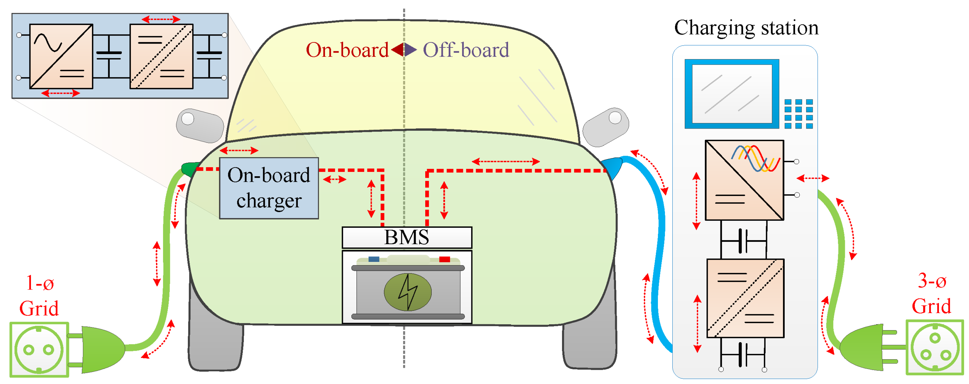
Figure 1. Illustration of EV charging architectures: on-board and off-board configurations. The left side depicts a single-phase on-board charger integrated into the vehicle. The right side shows a three-phase off-board station delivering regulated high-voltage DC via a power interface.
Batteries 11 00341 g001
Figure 2. Architecture of a modular DC fast charging station with integrated local storage and bidirectional capability.
Batteries 11 00341 g002
Figure 3. Simplified schematic of a single-phase Boost PFC converter.
Batteries 11 00341 g003
Figure 4. Two -phase interleaved Boost PFC.
Batteries 11 00341 g004
Figure 5. Effect of interleaving accuracy on input current ripple in a two-phase Boost PFC. Perfect 180° interleaving minimizes ripple, while a 5° phase error introduces residual oscillations.
Batteries 11 00341 g005
Figure 6. Bridgeless totem-pole PFC topology.
Batteries 11 00341 g006
Figure 7. Three-phase Vienna rectifier.
Batteries 11 00341 g007
Figure 8. Three-phase T-Type PFC.
Batteries 11 00341 g008
Figure 9. Detailed schematic of an isolated flyback converter.
Batteries 11 00341 g009
Figure 10. Schematic of a forward converter.
Batteries 11 00341 g010
Figure 11. Schematic of a push–pull converter.
Batteries 11 00341 g011
Figure 12. Schematic of an LLC resonant converter.
Batteries 11 00341 g012
Figure 13. Schematic of a PSFB converter.
Batteries 11 00341 g013
Figure 14. Schematic of a Dual Active Bridge converter.
Batteries 11 00341 g014
Figure 15. Total power loss vs. switching frequency for four technology types.
Batteries 11 00341 g015
Figure 16. Normalized radar chart comparing performance trade-offs of major transistor technologies.
Batteries 11 00341 g016
Figure 17. Operating domains of semiconductor technologies by voltage, power, and frequency.
Batteries 11 00341 g017
Figure 18. Common Li-ion form factors: Cylindrical (left), prismatic (center), and pouch (right). Chemistry and format are not uniquely coupled; each format is used with multiple chemistries.
Batteries 11 00341 g018
Figure 19. Qualitative comparison of NMC, NCA, and LFP across safety, cost, thermal robustness, energy density, and fast-charge capability (normalized axes).
Batteries 11 00341 g019
Figure 20. High-level functional blocks of a BMS: SoC/SoH estimation, power management, insulation monitoring, modular sensing.
Batteries 11 00341 g020
Figure 21. Centralized coordination of BMS functions: estimation, thermal control, fault handling, and charge interface.
Batteries 11 00341 g021
Table 1. Scenario-based distribution of bidirectional systems in new deployments (light-duty). Percentages refer to shares of new annual installations.
Metric (New Deployments)2024 (Baseline)2030 (Reference)2035 (Accelerated)
EVs with bidirectional-capable OBCs [% of new EVs]2–6%15–25%35–55%
Home AC chargers bidirectional-capable [% of new AC]<1%5–10%10–20%
Public DC chargers bidirectional-capable [% of new DC]<1%3–8%8–15%
Notes. (i) The Reference 2030 case assumes broad availability of ISO 15118-20 BPT in CCS ecosystems and continued policy support for smart charging, with regional variability. (ii) The Accelerated 2035 case reflects wider grid code enablement and attractive V2G tariffs/programs. (iii) These ranges synthesize public projections for EV and charger growth with market analyses of V2G enablement; they are consistent with recent IEA outlooks for charging expansion and with industry analyses of bidirectional value streams. Designers can use the ranges as guardrails when choosing between unidirectional vs. bidirectional architectures and when sizing communication, control, and protection layers.
Table 2. Qualitative comparison of Boost PFC efficiency versus switching frequency for different device technologies.
TechnologyTypical Optimal f s Efficiency Trend with f s Design Implication
Si MOSFET/IGBT20–50 kHzSharp drop above 50 kHz due to switching lossesLarge inductors/capacitors required
SiC MOSFET50–150 kHzFlat efficiency up to ∼150 kHz; mild drop at higher f s Reduced passive size, good thermal margin
GaN HEMT100–500 kHzHigh efficiency sustained up to MHz-class operationEnables compact magnetics, tighter EMI design
Table 3. Current balancing in interleaved Boost PFC: methods, pros/cons, and implementation complexity.
MethodBalancing AccuracyLoss/Cost ImpactComplexity
Passive droop (series R/DCR)MediumEfficiency penalty (on R)Low
Average current-mode (equal refs)HighMinimal (sensing required)Medium–High
Master–slave (share bus)Medium–HighMinimalMedium
Coupled inductors/IPTHighMagnetics cost/volumeMedium–High
Digital calibration/trimmingComplements aboveNegligible (runtime)Medium (FW/test)
Table 4. Overview of AC/DC front-end topologies in EV chargers [46,47,48].
TopologyPowerInputISOBi-dirPFCEff.RippleTHDPassiveControl
Boost PFC1–3 kW1 ϕ NoNoYes 97%Medium<5%MediumLow
Interleaved Boost3–6 kW1 ϕ NoNoYes 97%Low<5%Small–MedMed
Totem-Pole PFC1.8–7 kW1 ϕ NoOptionalYes97–99%Very low<5% (even <2%)SmallHigh
Vienna Rectifier10–20 kW3 ϕ NoNoYes>97%Low<5%MediumMed–High
T-Type PFC10–30 kW3 ϕ NoNoYes>97%Low<5%MediumHigh
Table 5. Comparison of theoretical vs. measured performance of common filter topologies in OBCs. Attenuation and THD values are representative of the literature/industrial prototypes.
Filter TypePower RatingAttenuation @ f s Grid Current THDEfficiency Impact
L (2.5 mH)3.3 kW, 1 ϕ ∼15 dB∼7%<0.5% loss
L C (1.5 mH + 5 μF)6.6 kW, 1 ϕ >25 dB∼4%∼0.3% loss
LCL (0.7 mH + 6 μF + 0.7 mH)11 kW, 3 ϕ ∼40 dB<2%, PF > 0.99<0.5% loss (with damping)
LCL + trap (tuned at 100 kHz)22 kW, 3 ϕ 20 dB narrowband<2%, CISPR 25 Class 5∼0.5–1% loss
Table 6. Recommended guidelines to mitigate battery degradation in DAB-based V2G operation.
ParameterTypical GuidelineRationaleImpact on Degradation
SOC window30–70%Avoids high-SOC stress and low-SOC deep cyclesReduces SEI growth, Li plating risk
C-rate≤0.3–0.5CLimits cycling stress and heat generationExtends cycle life
Temperature20–35 °COptimal range for Li-ion chemistryMinimizes thermal aging
Ripple current<1–2% I rated Use DC-link and LC filtersPrevents local heating, impedance rise
Power ramp rate≤0.2 P rated /sControlled transientsAvoids high instantaneous C-rate
BMS schedulingSOH- and T-awareAdaptive derating of V2G servicePreserves long-term capacity
Table 7. Comparative analysis of isolated DC/DC topologies for OBC integration.
TopologyPower RangeZVS/ZCSBidirectionalEMI/THDFreq. (kHz)ComplexityWBG Ready
Flyback<300 WNoNoHigh50–100LowYes
Forward<1 kWNoNoMedium50–150MediumYes
Push–Pull1–2 kWPartialNoHigh50–150MediumYes
Half-Bridge1–6.6 kWZVSNoLow100–300MediumYes
LLC3–22 kWZVS/ZCSNoVery Low150–500HighYes
PSFB6–22 kWZVSNoMedium100–250HighYes
DAB3–22 kWZVS/ZCSYesLow100–500Very HighYes
Table 8. Comparison of power semiconductor technologies for OBC applications.
ParameterSiIGBTSiC MOSFETGaN HEMT
Bandgap (eV)1.11.13.23.4
Breakdown Voltage (V)<600600–1700600–3300up to 650
On-Resistance at 25C (mOhm)LowMediumVery LowLow
Switching Frequency<100 kHz<50 kHz<500 kHz>1 MHz
Switching LossesHighVery HighLowVery Low
Thermal Conductivity (W/mK)150150490130
Max Junction Temp (C)up to 150up to 175above 200above 200
Gate Drive ComplexityLowMediumMediumHigh
Relative Cost1.5×3–4×4–5×
Technology MaturityHighHighMediumLow
Table 9. Transformer-only efficiency (typical ranges) vs. operating frequency for common OBC architectures. Values assume optimized magnetics and automotive thermal constraints; they serve as design guides, not limits.
Architecture50–150 kHz150–300 kHz300–500 kHzNotes (Materials and Winding Options)
LLC (two-stage AC/DC + DC/DC)99.3–99.7%98.9–99.5%98.3–99.1%Ferrite E/EI/ER cores; litz for round-wire, planar viable >200 kHz; efficiency mildly drops with f as R AC and core losses grow.
PSFB (hard/soft-switched)99.3–99.7%98.8–99.4%98.0–98.8%Often run at lower f for lower R AC ; leakage tailored for ZVS energy. Planar feasible with careful window utilization.
DAB (bidirectional)99.2–99.6%98.8–99.4%98.2–99.0%Leakage intentionally used as series L; circulating current drives copper loss sensitivity. Planar helps repeatability of leakage.
Single-stage resonant (LLC-like)98.7–99.3%98.0–99.0%Higher f to reduce bulk; planar preferred; tighter EMI/thermal co-design.
HV–LV auxiliary (HV→12 V)99.0–99.5%98.6–99.2%98.0–98.8%High secondary currents; prioritize low- R AC windings and short paths.
Table 10. Summary of transformer characteristics in typical OBC architectures.
ArchitectureTransformer LocationFreq.FunctionAdvantagesChallenges
AC/DC + DC/DCAfter PFC50–250 kHzIsolation and scalingModular, flexibleTwo stages, volume
Single-stage LLCAfter rectified AC150–500 kHzResonant isolationHigh efficiencyComplex regulation
DABBetween bridges100–400 kHzBidirectional energyV2G-ready, modularSynchronization
HV–LV auxiliaryBetween HV/12 V rails100–300 kHzVoltage reductionCompact, efficientHigh I sec
Modular/interleavedOne per module200–500 kHzIsolation + filteringScalable thermal loadMagnetic complexity
Table 11. Representative Li-ion chemistry metrics at cell level (indicative ranges).
MetricNMCNCALFP
Nominal voltage [V]3.6–3.73.6–3.73.2–3.3
Gravimetric energy density [Wh/kg]150–220200–260100–160
Volumetric energy density [Wh/L]350–600450–700250–450
Continuous C-rate [ h 1 ]1–21–2.51–3
10 s peak C-rate [ h 1 ]3–55–75–10
Typical cycle life (full cycles) [–]1000–20001000–15002000–5000
Thermal stability/abuse tolerance [qual.]ModerateLowerHigher
Fast-charge sensitivity (plating risk) [qual.]Moderate–HighHighModerate
OCV slope for SOC estimation [qual.]FavorableModerateFlat (needs high-res BMS)
Indicative cost [USD/kWh, rel.]Medium–HighHighLow–Medium
Table 12. Format-driven attributes impacting pack integration and durability.
AttributeCylindricalPrismaticPouch
Packing efficiency [qual.]Medium (voids)HighMedium–High
Thermal pathRadial/axial (1D)Through-plane + in-plane (2D)Short path; needs preload
Mechanical robustnessHigh (shell)High (rigid can)Lower; needs fixture
Swelling managementMinimalShell expansion managementRequires compressive frame
Manufacturing throughputHighMedium–HighMedium
Serviceability/module designMature busbarsStraightforward stackingRequires careful clamping
Typical chemistry pairings (non-exclusive)NMC/NCALFP/NMC/NCANMC/NCA/LFP
Table 13. Nomenclature of symbols and parameters for battery packs.
SymbolUnitMeaning
N s Number of cells in series (defines pack voltage)
N p Number of parallel cell strings (defines pack current capability)
V OC VOpen-circuit voltage of a cell (or pack)
V pack VPack voltage under operating conditions
Q nom AhNominal cell capacity at reference conditions
C-rate h 1 Normalized current: I / Q nom (e.g., 1C = full charge in 1 h)
SOC% or –State of charge (fraction of available capacity)
SOH% or –State of health (capacity or impedance relative to beginning of life)
R int Ω Internal resistance (cell or pack)
Table 14. OBC design constraints associated with different battery technologies and architectures.
Design ConstraintNMC/NCALFPHigh-Voltage PacksLegacy Low-Voltage Packs
OBC output voltage range [V]250–850220–700500–100048–150
Required output power [kW]6.6–223.3–1111–43<3.3
Voltage regulation resolutionMediumHighVery highLow
Current ripple tolerance<1% peak<2% peak<0.5% peak<5% peak
Insulation levelStandard (1+ kVDC)Standard (1+ kVDC)Enhanced (2.5+ kVDC)Optional
Control loop dynamicsFast (VOC slope)Slower (flat VOC)Fast with stability constraintsSlow
Feedback bandwidth requiredMedium–highMediumVery highLow
Balancing and BMS coordinationStandardHigh-accuracy neededCritical for safetySimplified
Thermal derating interfaceTemperature-dependent limitsSOC–T joint profilingActive derating enforcedPassive
OBC-to-BMS communicationCAN FD/ISO 15118CAN FD/ISO 15118Dual bus, high-res updatesBasic CAN
V2G readiness (bidirectional)SupportedSupportedRequiredNot applicable
Table 15. Battery-side ripple mitigation options: typical use, sizing focus, and trade-offs.
OptionTypical UseSizing HighlightsPros/Cons
Passive LC filterHigh-frequency ripple ( f s ) f c [ f s / 10 , f s / 20 ] ; L from Δ I batt , pp ; low-ESR film capacitorsSimple, robust, low cost/large C for very low ripple; potential resonance with control loop
LCL filter with dampingHF + pack/line interactions L 1 , L 2 , C chosen for staged cutoff; R d for Q 0.7 dampingHigh attenuation with smaller L/Requires damping, more complex stability design
Active Ripple Port (ARP)Low-frequency 2 ω decoupling; V2G services C ARP from oscillation energy E amp and allowed Δ V Drastically reduces HV capacitance; scalable/Extra stage and cost
Hybrid (LC + ARP)HF + LF ripple in high-density OBCsDesign LC for f s , ARP for 2 ω ; coordinate control loopsSuperior performance/Highest integration complexity
Table 16. Representative Tier 1 suppliers and their charging solutions.
SupplierProduct TypeCustomersPower [kW]Voltage [V]Highlights
BoschOBC, inverterVW, BMW, Mercedes3.3–22400–800Bidirectional charging, ISO 26262 compliance
MarelliOBC, inverterStellantis, Hyundai6.6–22400–800GaN-based topologies, compact form factor
Hyundai MobisOBCHyundai, Kia11–22800Integrated HV power module
DensoOBC, PDUToyota, Honda3.3–6.6400High reliability, compact integration
Table 17. Representative Tier 2 suppliers of power electronics components.
CompanyComponent TypeApplicationPackageNotes
InfineonSiC/GaN power modulesOBC, inverterEasyPACK, CoolSiCAutomotive-qualified, high efficiency
STMicroelectronicsControllers, driversOBC, DC/DCQFN, TSSOPPFC and LLC stage control
Würth ElektronikMagnetics, chokesEMI filters, transformersCustom/standardDesigned for high-frequency resonant topologies
Texas InstrumentsGate drivers, monitorsAll stagesSOIC, QFNIsolated drivers with fault detection
Table 18. Representative Tier 3 suppliers of materials and passive components.
SupplierMaterial TypeApplication AreaKey Property
HenkelThermal pastes and adhesivesPower modules, PCBsHigh thermal conductivity
LuvataCopper wire and stripsMagnetics, busbarsHigh purity, low resistance
FerroglobeMetallurgical siliconSemiconductor baseSource for Si/SiC production
Sumitomo ElectricEnameled wire, insulatorsHV magneticsAutomotive-grade insulation
Disclaimer/Publisher’s Note: The statements, opinions and data contained in all publications are solely those of the individual author(s) and contributor(s) and not of MDPI and/or the editor(s). MDPI and/or the editor(s) disclaim responsibility for any injury to people or property resulting from any ideas, methods, instructions or products referred to in the content.