1. Introduction
The growing adoption of electric vehicles (EVs) has led to an increasing number of used lithium-ion batteries reaching the end of their first life. Although these batteries may no longer meet the stringent performance requirements for vehicular applications, they retain significant capacity that can be repurposed for stationary energy storage [
1]. The efficient utilization of second-life batteries presents a viable solution to mitigate environmental impact, reduce costs, and enhance the stability of the energy system by integrating renewable energy sources. In addition, it supports grid operators by reducing the dependency on expensive peak power generation, facilitating a greater integration of intermittent renewable energy sources, and improving overall grid resilience [
2,
3,
4]. The commercialization of second-life battery systems offers new business opportunities for battery manufacturers, energy companies, and technology developers, fostering job creation and technological advancement in the energy sector.
Despite its potential, several open research questions remain in the field of second-life battery applications. These include optimizing methods for assessing battery health and degradation patterns, developing standardized protocols for battery reuse, and ensuring long-term reliability and safety in real-world applications. In addition, more research is needed on economic models that balance cost-effectiveness with regulatory compliance and market dynamics. Addressing these challenges will be crucial to unlocking the full potential of second-life battery storage and establishing it as a viable alternative in the renewable energy landscape.
The current state of research shows that economic benefits can be diminished by unexpected losses in performance and reliability. For instance, second-life batteries can potentially be more expensive than new batteries at grid scale according to [
5]. One of the reasons for this is the need to examine the aged cells before they are used in a second-life application. This situation is also reflected in the literature, where numerous procedures for the pre-qualification of used EV batteries are described [
6,
7,
8]. Furthermore, the potential risk of thermal runaway and its propagation from a faulty EV battery to the entire system must be considered when designing the overall system [
9].
This research aims to develop and implement a scalable stationary energy storage system using complete, non-refurbished second-life EV batteries that can be installed cost-effectively and operated safely. Instead of disassembling battery packs into individual modules or cells, which requires significant labor, introduces safety risks, and complicates traceability and warranty issues, this approach focuses on reusing complete EV battery packs. Reusing full battery systems offers several advantages: It preserves the original structural integrity, including housing, battery management systems (BMS) and cooling systems, thereby reducing both repurposing time and costs. It also minimizes the risk of mechanical or electrical damage that could occur during disassembly and reassembly, improving safety and reducing liability concerns. However, this approach imposes specific technical requirements on the power electronics used in the system. Since different battery packs vary in chemical composition, voltage levels, capacity, state of health (SoH), and manufacturer-specific configurations, power electronics must be highly adaptable and capable of interfacing with a wide range of battery specifications. A key requirement is modularity and support for the parallel operation of heterogeneous battery packs while ensuring balanced power flow and system stability. This requires the use of DC/DC converters on a battery level with features such as a wide input/output voltage range, bidirectional power flow, and galvanic isolation to ensure safety and compatibility. Many different designs for DC/DC converters exist and have been evaluated and used in stationary battery storage systems in the past [
10,
11,
12,
13]. In particular, the well-known DAB converter [
14,
15,
16] offers many advantages, particularly in terms of power density. In this work, an optimized DAB was developed and tested for use in stationary storage systems, specifically designed to handle the challenge of a wide input voltage range while maintaining high efficiency and operational flexibility.
In addition, the converter enables precise control of charging and discharging processes—a crucial factor in maintaining performance and prolonging the service life of aged batteries. Lastly, the thermal management of used EV batteries is emphasized to improve their reliability and extend their service life in battery storage systems. This paper outlines the general technical design considerations and safety measures for second-life EV battery storage. The findings will contribute to the advancement of circular economy principles in battery technology, the promotion of sustainable energy storage solutions, and the support of the broader transition to renewable energy systems.
2. Specifications and Overall Design
The second-life EV batteries will be integrated into a modified 20 foot ISO standard container (6050 × 2430 × 2890 ), partitioned into four separated and thermally insulated compartments. One compartment is reserved for power electronics (DC/AC converter, DC/DC converters) and the energy management system (EMS). The remaining three compartments will house up to 12 battery units mounted on heavy duty shelving. The internal structure is designed for modularity, safety, and maintainability. Accessibility is ensured through the outward opening doors of all compartments, with all controls externally operable. Additionally, the system must accommodate EMS components, smart metering equipment, and future upgrades. In a first step, it is planned to use repurposed Nissan Leaf 40 traction batteries, which would result in a total storage capacity of . The connection to the power grid and local consumers is then established through a 3 × 400 system with a three-phase bidirectional AC/DC inverter rated at 400 kVA, allowing charging and discharging. The connection to the power grid is realized via a commercially available bidirectional inverter that complies with relevant European standards and supports both on-grid and off-grid operation modes. To demonstrate modularity and scalability, the system will be equipped with only six batteries in an initial phase. However, all electrical and structural components are dimensioned and preinstalled such that they can accommodate the final expansion stage.
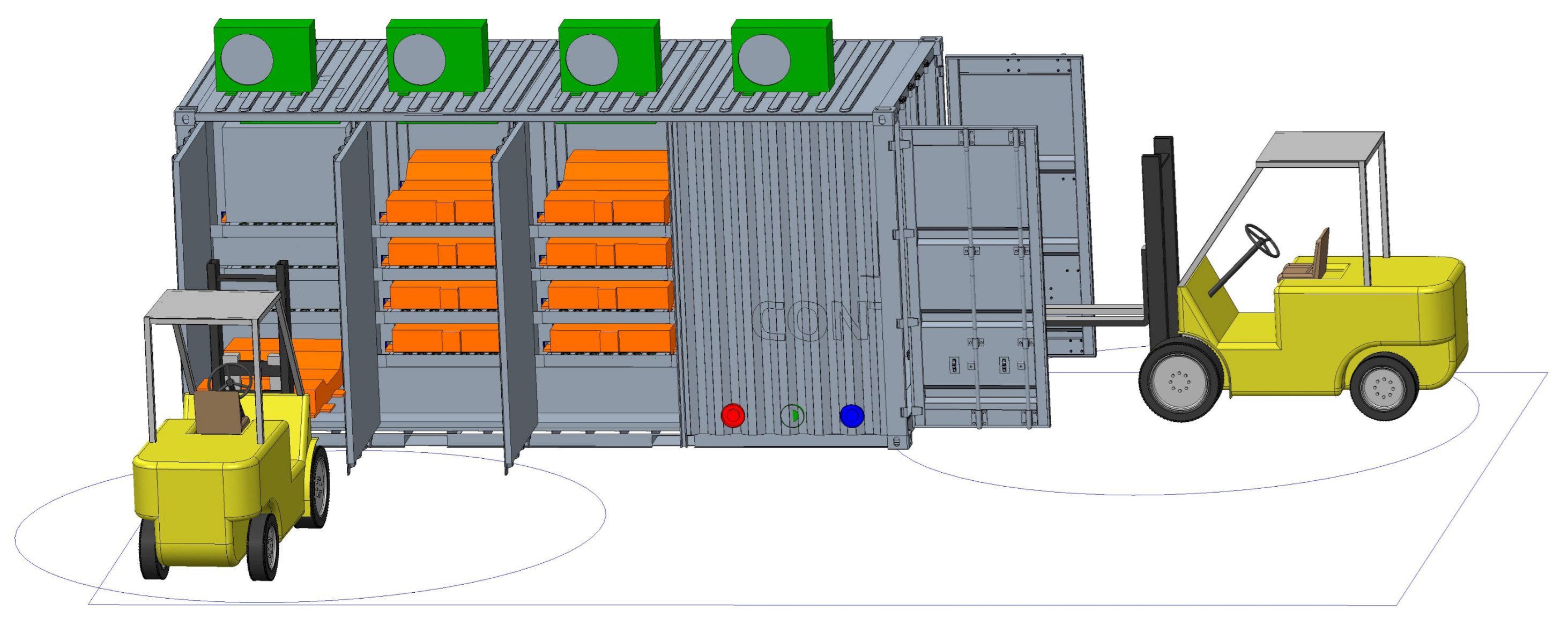
The installation of the second-life battery container system requires site-specific preparatory work to ensure structural integrity and operational accessibility. The designated installation site is an unsheltered outdoor environment, necessitating consideration of environmental exposure in the container’s structural and material design. Suitable clearance must be provided around the installation to facilitate routine maintenance, emergency access, and maneuvering of the equipment, such as forklifts or lifting gear shown in
Figure 1. All electrical and control interfaces, including the main three-phase grid connection, signal pathways to supervisory control systems, and auxiliary EMS power supply, are to be centralized within a dedicated service compartment.
Second-life battery systems must accommodate a wide variety of battery types, each with different voltage ranges, capacities, and degradation profiles. In addition, variability in chemical composition (e.g., NMC, LFP) and internal resistance among these batteries complicate their direct integration into a unified storage system. To address these challenges, a system concept is required that can reliably manage the heterogeneous characteristics of second-life batteries. Such a concept must support individual battery management, enable the flexible integration of different battery types from various manufacturers, and ensure safe and efficient operation across a wide range of electrical parameters. Therefore, the system comprises multiple galvanically isolated DC-DC converter modules as shown in
Figure 2, where each battery is connected to its own dedicated DC-DC converter. The converter has a power capacity of 50 kW and operates in a voltage range of 150 V to 900 V, supporting all the different second-life batteries available on the market. To ensure balanced power flow and system stability during the parallel operation of heterogeneous battery packs, each DAB converter operates independently and is controlled by the central EMS. The system supports decentralized regulation based on real-time SoC, SoH, and temperature data, allowing for coordinated current sharing without requiring direct electrical coupling of the batteries. This modular architecture prevents reverse current flow between battery units and ensures stable operation across varying battery types and aging conditions. In the event of a battery failure, the associated DAB converter can be used to electrically isolate the affected battery from the system.
The system is designed for scalability and future extension, with dedicated slots for additional battery types. Communication and control are managed through a central EMS, which communicates using CAN or Modbus protocols. The EMS supervises system operations, monitors battery status, and optimizes energy flows. Auxiliary systems include dedicated units for heating or cooling the container and fire protection, ensuring operational safety and thermal management. These subsystems are also integrated into the EMS via CAN communication, enabling real-time monitoring and response.
3. Safety Considerations
The relevant guidelines were studied before the start of the design process. The overall system design adheres to the specifications outlined in DIN EN IEC 62485-1 (VDE 0510-485) and IEEE 2030.2.1:2019 [
17]. In addition, a risk analysis was performed to identify the greatest potential risks and possible measures to mitigate them (see
Table 1). However, a battery system sourced from an accident-free electric vehicle is considered inherently safe because it was originally developed according to strict automotive standards. In addition, the introduction of the battery passport, as included in the forthcoming EU regulations, represents a significant advancement in the traceability and life-cycle management of batteries.
The most significant potential hazard is posed by battery fire. Accordingly, the preventive and protective measures implemented for this scenario are described in more detail. The fire containment strategies reference the provisions of DIN EN 12101. Based on this, a containerized second-life battery storage system must be comprehensively structured to address the unique hazards associated with lithium-ion battery technology, particularly the risks of thermal runaway, thermal propagation, smoke development, and toxic gas release. By dividing the container into separate compartments, the spread of fire will be limited. This concept therefore increases both sustainability and safety.
The provisions cover early fire detection, passive fire protection, and active fire suppression, all of which are compartmentalized and designed for autonomous operation. Hence, each of the four container compartments is equipped with an independent smoke detection system. These systems serve as the primary means of early fire detection, based on the understanding that lithium-ion battery fires are typically preceded or accompanied by significant smoke emissions [
18]. The detectors operate independently of the main container control and EMS, ensuring continuous functionality even in the event of a system-wide failure. Each detection unit is connected to an externally installed audible alarm – placed near the container – that provides immediate acoustic notification in case of fire. Moreover, the smoke detectors are integrated into the overarching fire alarm system of the site operator, enabling centralized monitoring and coordinated emergency response. Due to the inherent difficulty of extinguishing lithium-ion battery fires by conventional means, the system adopts a strategy focused on thermal containment and heat extraction through rapid water-based compartment flooding. For this purpose, each battery compartment is fitted with the following infrastructure:
Extinguishing Water Inlet: Each compartment is equipped with an independent extinguishing water connection designed to flood the entire compartment in 5 to 10 min. This flooding rate corresponds to the flow capacity of a standard B-type extinguishing hose. The four batteries in each compartment are mounted on specialized trays that are filled with water simultaneously. The flooding of the remaining compartment volume begins only after all batteries are fully submerged. This procedure is intended to rapidly dissipate thermal energy and inhibit the propagation of fire.
Overflow Nozzle: Positioned near the roof of each compartment, the overflow outlet prevents overpressure and ensures controlled evacuation of gases and water during compartment flooding. Non-return valves are installed to prevent air exchange during normal operation.
Drainage Outlet: Each compartment includes a low-mounted extinguishing water outlet with a manual shut-off valve. This facilitates controlled disposal of contaminated fire water post-extinguishing and prevents the environmental release of toxic effluent. The system ensures nearly complete drainage of extinguishing fluids.
4. Design of Thermal Management System
4.1. Cooling Circuit Concept
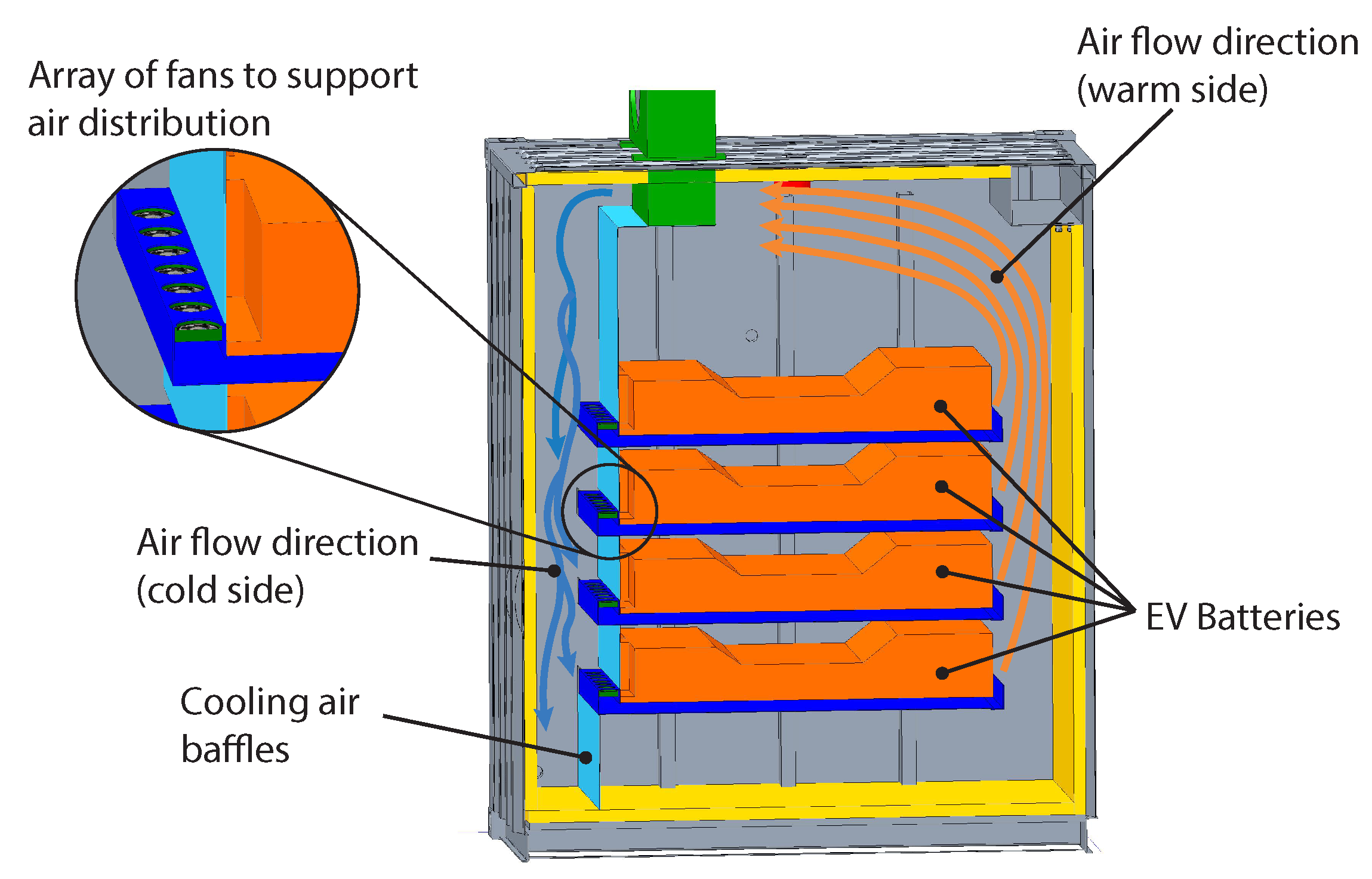
The aim of thermal management is to achieve a stable and homogeneous temperature within the individual batteries. In addition to the heat caused by ohmic losses in the battery, ambient conditions must also be taken into account when designing the cooling system. For this reason, each individual compartment of the container is equipped with a commercially available ceiling cooler with sufficient cooling capacity. For an exemplary dimensioning, we consider the air-cooled traction batteries mentioned above, which were originally utilized in the Nissan Leaf EV. In their automotive application, cooling is achieved passively by using ambient airflow generated by vehicle motion. Consequently, the surrounding air acts as the only cooling medium. However, in a stationary and closed container environment, dynamic airflow is absent. Air movement is restricted to free convection, which is insufficient to maintain safe operating temperatures. Therefore, to ensure adequate thermal regulation, forced convection must be employed, which requires the use of one or more circulation fans. These fans facilitate air movement over the battery modules, allowing air to absorb and transport waste heat. To maintain uniform flow conditions, forced circulation is required within the container. This can be achieved through the use of a powerful fan integrated with the ceiling air cooler, as well as additional fan systems positioned to support air distribution. The use of both systems is recommended to improve redundancy and ensure operational safety. Cooling air baffles, as illustrated in
Figure 3 are required to direct airflow through the bottom cooling channels and prevent recirculation of heated air. Even if batteries from other EV manufacturers with liquid cooling are used in the future, air conditioning of the container interior will still be necessary to compensate for the heat exchange with the environment.
4.2. Thermal Load Calculation
As mentioned above, a first-generation Nissan Leaf battery pack is used as an example to calculate the thermal load. As stated in [
19], it can be assumed that aged batteries exhibit increases in ohmic and diffusion resistance of 100% and 35%, respectively. This results in a total resistance of
per cell, which with a 96S2P configuration leads to a total battery resistance of approximately
. To preserve second-life batteries, currents should be significantly reduced compared to the first-life EV application. Therefore, a maximum continuous current of
is chosen for the thermal load calculation, which corresponds to approximately 0.3C. In [
19], the efficiency was determined to be 95.7% at 0.5C, and it is recommended not to exceed this current load. The worst-case continuous thermal power loss of the entire battery is therefore
. However, the battery may be subjected to higher current levels for short durations, which must be managed by the DAB converter, while the EMS ensures that the average thermal load does not exceed 170
over extended periods. Furthermore, the DAB converter is designed with other battery types in mind, where 0.5C corresponds to current levels above 100
.
The amount of heat that can be dissipated depends on the heat transfer surface area
, the inlet temperature
and the heat transfer coefficient
at the interface. For effective cooling, a dedicated airflow channel must be implemented beneath each battery module. The air must pass directly over the battery base, without intermediate partitions or barriers. The dimension of the flow channel in this application was chosen to be 1.1 m × 0.04 m × 1.55 m (W × H × L), leading to an active heat transfer surface of
. To achieve turbulent flow, a velocity of at least
2
/
is necessary. In combination with the hydraulic diameter of
, the Reynolds number can be calculated as
where
is the density, and
is the dynamic viscosity of air. Furthermore, the Prandtl number is
where
is the specific heat and
is the thermal conductivity of air. Since
10,000 a turbulent flow is assumed, the Nusselt number is calculated according to
hence the resulting heat transfer coefficient can be estimated to be
The minimum flow conditions required can be derived from Equations (1)–(4), which are as follows for the Nissan Leaf battery.
Flow rate:
Flow channel size (W × H × L): 1.1 m × 0.04 m × 1.55 m
Maximum inlet air temperature:
A dynamic control strategy must be implemented to regulate the inlet temperature of the cooling air based on the real-time power dissipation of each battery. The goal is to maintain the temperature on the bottom side of the battery at approximately 25°. Variations due to different aging states are expected, but under no circumstances should any module exceed a base temperature of 30°.
As previously mentioned, ambient conditions are a critical factor in the design of the thermal management system. To estimate heat exchange with the environment, a compartment measuring 1.45 m × 2.3 m × 2.12 m (L × W × H) was considered, subjected to an ambient temperature range of −20 °C to 55 °C. To minimize heat transfer, the outer walls of the container are thermally insulated using extruded polystyrene (XPS) panels with a thickness of
and a thermal conductivity of
. Assuming that at least one wall of each compartment faces inward, the maximum exposed surface area is estimated as follows:
resulting in an overall thermal conductance of
The corresponding heat flow from the environment into the compartment is then calculated to be
assuming a target internal temperature of 15 °C. This analysis indicates that four battery units operating at maximum continuous load (
) would produce sufficient heat to maintain the desired internal temperature. However, the system must be designed to accommodate worst-case scenarios, such as when no heat is generated by the batteries.
Therefore, each compartment must be equipped with a dedicated control circuit capable of monitoring and adjusting airflow or re-cooling parameters accordingly. The maximum cooling capacity required per compartment is approximately (i.e., ), whereas the maximum heating capacity needed under low-temperature conditions without battery operation is about 500 .
5. Electrical Design Concept
5.1. Topology Selection and Specification
The selection of a suitable DC-DC converter topology is critical to meet the functional and safety demands of the modular second-life battery system. To fulfill these requirements, the selected topology must satisfy the following key requirements:
Bidirectional power flow to enable both charging and discharging.
High efficiency (>98%) to ensure energy savings during prolonged usage.
Galvanic isolation to enhance operational safety and protect against fault propagation.
Modular architecture for scalability and maintainability.
Accurate measurement and control capabilities in constant current (CC) and constant voltage (CV) mode to accommodate a wide range of battery characteristics.
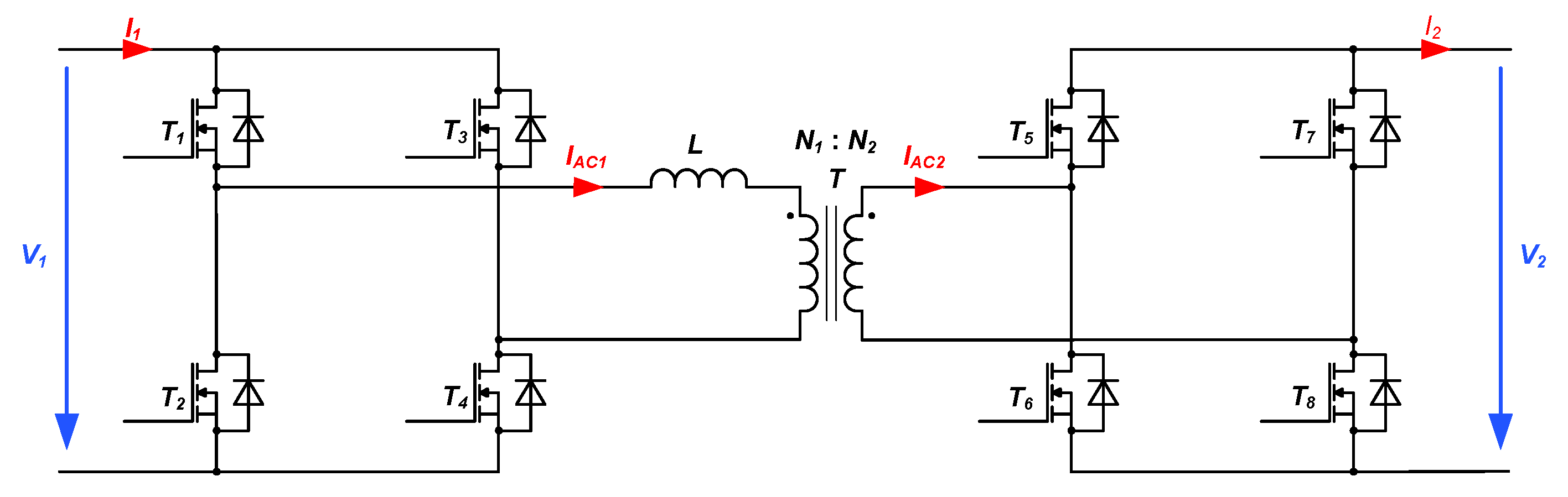
The DAB topology shown in
Figure 4 was selected for its ability to provide efficient bidirectional power conversion over a wide voltage range. Unlike resonant converters (e.g., LLC), which are efficient only within a narrow conversion ratio, or phase-shifted full-bridge converters, which require complex modifications for reverse power flow, the DAB inherently supports bidirectional operation and wide-range voltage conversion.
It consists of two full-bridge circuits—one on the primary side and one on the secondary side—connected via a high-frequency transformer. Each bridge is formed by four power switches that allow bidirectional energy transfer by modulating the phase shift and duty cycle between the primary and secondary bridge voltages. In addition, the use of high-frequency operation enables compact magnetic components and a fast dynamic response. Its symmetrical structure and galvanic isolation allow integration of battery modules with different voltage levels while maintaining safety.
The converter is designed to connect batteries with voltages ranging from 150 V to 900 V to a common 800 V DC-Link. This flexibility is essential for integrating batteries with varying SoH and chemistries. The galvanic isolation provided by the DAB enhances safety, especially in systems where battery types are not predefined. Based on the electrical design and the variety of batteries that may be used, the DC-DC converter must meet the electrical and mechanical specifications according to
Table 2.
5.2. System Design Optimization
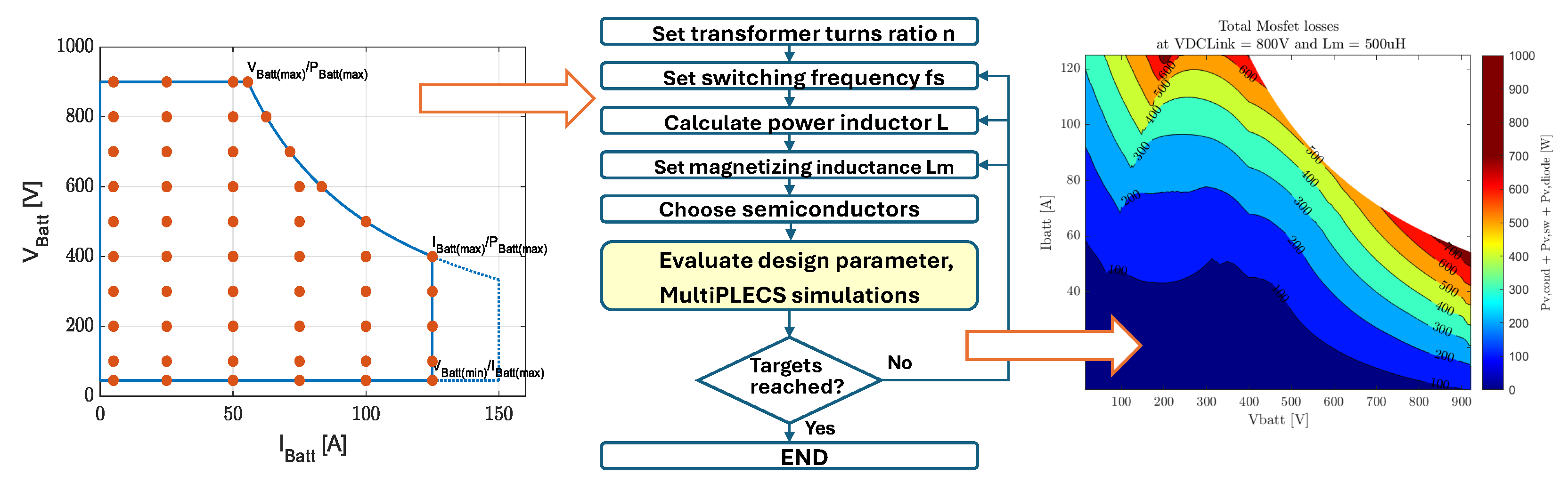
The DAB converter optimization process, as illustrated in
Figure 5, follows a structured and iterative approach to achieve efficient power conversion. It begins with setting the ratio (
n) of the number of turns of the transformer and the switching frequency (
), which are critical when defining the converter operating range. The DAB converter operates more efficiently when the transformer turn ratio
is close to the input–output voltage ratio
[
20]. If the DAB has a wide input- or output voltage range, and therefore a mismatching of the voltage conversion gain, the soft-switching (ZVS) region on the primary and the secondary side decreases for low output current values. Calculations under ideal conditions considering the influence of the output capacitance of the semiconductor
and the minimum current required for soft switching are presented in [
20]. Based on the specifications from
Table 2 for maximum power transfer, the minimum battery voltage
, DC-Link voltage
and the maximum series inductor size is determined by
The inductor must be small enough to transfer the maximum power to the output. A lower inductance value leads to higher conduction losses, so the inductance should not be smaller than necessary. Next, the transformer magnetizing inductance () is set.
The semiconductor components are then selected based on performance and thermal characteristics. The design is evaluated using MultiPLECS simulations, which simulate the converter’s performance under various load conditions. An iterative optimization process is employed in which various design parameters, such as transformer turn ratio, switching frequency, and filter components, are systematically varied. At each iteration, the system is evaluated to determine whether the target specifications for voltage, current, and efficiency are met throughout the operating range. If the criteria are not satisfied, the parameters are adjusted accordingly. The configuration that yields the highest overall efficiency while meeting all operational requirements is ultimately selected.
The graphs, shown in
Figure 5, indicate this process. The graph on the left shows how the battery voltage (
) varies with current (
), helping to define the operational limits. The right contour plot visualizes the total switch losses at a fixed DC link voltage and magnetizing inductance, guiding the designer toward configurations that minimize power loss. This comprehensive approach ensures that the DAB converter is optimized for both system design and efficiency.
6. Results
6.1. Prototype Development and Optimization
A 50kW prototype, shown in
Figure 6, of the DAB-based DC-DC converter has been developed and tested. The second version of the prototype demonstrated significant improvements in efficiency, achieved through transformer optimization and refined control strategies. The converter is fully functional and is being integrated into a rack-mounted format for deployment in a modular energy storage container. Efficiency measurements indicate that the converter maintains high performance across a broad load range, which is critical for second-life applications where battery packs may operate at reduced C-rates due to aging.
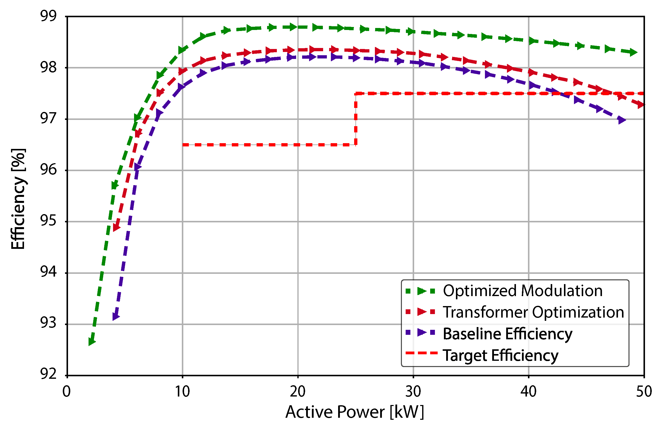
To optimize the performance of the DAB converter, five prototype transformers were designed and evaluated in an iterative process. Each iteration focused on improving size, thermal management, and minimizing losses. Characterization and measurement data guided successive refinements, leading to significant reductions in core and copper losses, as well as improved thermal behavior during continuous operation. The final design, shown in
Figure 6, also incorporated enhancements to ensure industrial applicability and manufacturability, including simplified winding structures and improved cooling integration. As part of the optimization process, the required leakage inductance was integrated directly into the transformer design. This approach reduces space requirements, costs, and total power losses. The resulting efficiency improvements are illustrated in
Figure 7. In parallel, the modulation strategy was optimized to further enhance the converter performance. Using a dedicated optimization algorithm, the control scheme was dynamically adapted based on the operating point. This involved adjusting both the gate signal timing and the switching frequency to extend the soft-switching range and reduce RMS current in both the transformer and switching devices. These optimizations collectively resulted in a substantial decrease in overall power losses. The final modulation strategy was implemented as a look-up table within the controller, allowing real-time adjustment based on load and voltage conditions. This co-optimization of transformer design and modulation control significantly improved the system’s efficiency and thermal performance under realistic load conditions.
6.2. Performance Measurement for Nissan Leaf Batteries
The developed DAB converter was tested with second-life Nissan Leaf battery modules (type NMC 523, 40
capacity) across the full voltage range of the battery pack (307 V to 403 V) and load currents up to 125 A (approximately 1 C). The converter demonstrated excellent efficiency across a broad operating range, achieving a peak efficiency of 98.7% and a full-load efficiency of 98.3%. The test results, shown in
Figure 8, illustrate efficiency performance as a function of battery current for three voltage levels: minimum, nominal, and maximum battery voltage. The DAB’s control enabled soft-switching under varying conditions, contributing to consistently high efficiency even under partial load. These results confirm the converter’s ability to manage varying voltages and currents with minimal losses, validating its suitability for modular second-life battery storage systems, where cell conditions and voltages may differ significantly due to aging and pack configuration differences.
In order to demonstrate the universality of the developed converter topology, the converter specification is compared to a range of batteries from different suppliers. The most common cell material is NMC with an operating voltage range of 3 V to 4.2 V, while a smaller proportion of manufacturers use LFP, which operates in a range of 2.5 V to 3.65 V. Most batteries with 400 V architecture use a 96 s configuration, but the future trend could be towards 800 V architecture, as already used in the Ioniq-5 today. Based on the cell voltage range and the cell configuration, the minimum and maximum voltages of the whole battery pack can be determined. For the batteries given in
Table 3 the operation voltage is between 288 V and 806 V, respectively. Assuming a maximum load of 0.5C, the maximum required power of 44 kW and the maximum current of 116 A can be determined. The electrical specifications of the DAB as stated in
Table 2 meet all these requirements.
7. Discussion
The presented second-life battery storage system demonstrates how modular power electronics and thermal management can successfully address the challenges associated with reusing EV batteries. The system design was intentionally limited to a maximum of 12 s-life batteries, with each battery connected to its own DAB converter and dedicated CAN communication interface. This allows for individual monitoring and control, which is crucial when dealing with varying SoH and chemistries. The DAB topology proved particularly effective due to its inherent bi-directionality, galvanic isolation, and high efficiency across a wide voltage range. Compared to previous approaches such as nonisolated or resonant converters, DAB allowed for seamless integration of battery modules with varying SoH, chemistries, and voltage profiles—an essential requirement for second-life applications [
22,
23]. Transformer and modulation optimization played a central role in achieving peak efficiency values up to 98.7%. This performance is competitive with, or superior to, other published second-life battery system designs, which often suffer from thermal limitations or constrained voltage compatibility. However, there is an efficiency tradeoff between DC-DC converter and battery losses. The converter efficiency becomes lower at currents below 30 A. According to [
19], the recommended second-life working current is 0.2C to 0.5C to maintain high energy efficiency and long battery life. The maximum current should not exceed 0.5C which corresponds to low currents depending on the battery capacity. This presents a challenge because the converter was designed to be compatible with all types of second-life batteries. Depending on the capacity and age of the batteries, the converter may be operated in a power range where its efficiency is no longer optimal.
The use of a dynamic control algorithm with a precomputed look-up table significantly extended the soft-switching range and reduced current stress on switching devices and transformers. These innovations contribute to a more robust and scalable design, reducing the risk of thermal hotspots and premature failure in real-world deployments. The results highlight the importance of co-optimizing hardware and control strategies for second-life applications. Future research could focus on extending the DAB design to multi-phase configurations to further reduce ripple currents, as well as integrating adaptive SoH-based balancing strategies to maximize usable capacity over time. Long-term field data from containerized installations will also be crucial to validate the reliability and economic viability of such systems under realistic operating conditions.
8. Conclusions
This project has demonstrated the feasibility and benefits of a modular, containerized energy storage system using second-life EV batteries. By leveraging a flexible system design, the solution supports a wide range of battery voltages and chemistries while maintaining high efficiency and thermal safety. The use of individualized DC-DC converters per battery module enables independent control of energy flow, accommodating the heterogeneous nature of aged battery packs. An iterative design and optimization process for both the transformer and modulation scheme led to substantial improvements in power conversion efficiency and thermal performance. The final converter prototype achieved over 98% efficiency in laboratory tests, confirming the effectiveness of the selected topology and control approach.
In addition, the thermal and fire safety features of the system ensure its suitability for real-world deployment in industrial environments. Given the elevated internal resistances of second-life batteries, passive cooling is insufficient to ensure stable operation in a confined, stationary environment. To address this, each thermally insulated battery compartment is equipped with a commercially available ceiling-mounted air cooler and an array of forced convection fans, supported by strategically placed airflow baffles that guide cold air beneath the battery modules and prevent recirculation of heated air. The system is dynamically controlled to maintain battery base temperatures below 30 °C under all operating conditions, thereby reducing thermal stress and prolonging battery life. Furthermore, the thermal management system is fully integrated into the energy management and safety architecture, enabling proactive thermal regulation and rapid intervention in the event of overheating or thermal runaway. This design provides the foundation for safe operation and is expected to support long-term reliability and performance, although dedicated lifetime testing under real-world conditions will be conducted in future work.
The project contributes significantly to the circular economy by extending the useful life of lithium-ion batteries and reducing e-waste. While this architecture proved feasible in the laboratory, practical deployment at larger scales introduces new challenges. More long-term field tests are necessary to evaluate reliability, economic viability, and operational robustness under real environmental conditions. Therefore, efforts are underway to industrialize both the container design and the DAB converter for broader applications in collaboration with a Swiss partner.
Author Contributions
Conceptualization, S.N. and M.S.; methodology, C.M.; software, C.M.; validation, C.M.; writing—original draft preparation, R.C. and S.N.; writing—review and editing, M.S.; visualization, C.M., S.N. and R.C.; supervision, M.S.; project administration, S.N.; funding acquisition, S.N. All authors have read and agreed to the published version of the manuscript.
Funding
This research was funded by the Swiss Innovation Agency (Innosuisse) as part of the “Swiss Circular Economy Model for Automotive Lithium Batteries (CircuBAT)” grant number PFFS-21-20 within the scope of the flagship initiative (Agreement number: 2155009968/Reference number: 2150 009 478).
Data Availability Statement
The raw data supporting the conclusions of this article will be made available by the authors on request.
Acknowledgments
The authors would like to thank Alfred Gadola for the realization of the mechanical design and our former colleague, Gerhard Rizzo, for the design of the thermal system and his valuable contribution to the entire sub-project.
Conflicts of Interest
The authors declare no conflicts of interest.
Abbreviations
The following abbreviations are used in this manuscript:
| BMS | Battery Management System |
| CC | Constant Current |
| CV | Constant Voltage |
| DAB | Dual Active Bridge |
| EMS | Energy Management System |
| EV | Electric Vehicle |
| SoC | State of Charge |
| SoH | State of Health |
References
- Akram, M.N.; Abdul-Kader, W. Repurposing Second-Life EV Batteries to Advance Sustainable Development: A Comprehensive Review. Batteries 2024, 10, 452. [Google Scholar] [CrossRef]
- Lee, J.W.; Haram, M.H.S.M.; Ramasamy, G.; Thiagarajah, S.P.; Ngu, E.E.; Lee, Y.H. Technical feasibility and economics of repurposed electric vehicles batteries for power peak shaving. J. Energy Storage 2021, 40, 102752. [Google Scholar] [CrossRef]
- García-Plaza, M.; Eloy-García Carrasco, J.; Alonso-Martínez, J.; Peña Asensio, A. Peak shaving algorithm with dynamic minimum voltage tracking for battery storage systems in microgrid applications. J. Energy Storage 2018, 20, 41–48. [Google Scholar] [CrossRef]
- Yang, Y.; Bremner, S.; Menictas, C.; Kay, M. Battery energy storage system size determination in renewable energy systems: A review. Renew. Sustain. Energy Rev. 2018, 91, 109–125. [Google Scholar] [CrossRef]
- Sengor, I.; Hayes, B.P. Second Life Electric Vehicle Batteries for Stationary Energy Storage Applications: An Analysis of Technical and Economic Feasibility. In Proceedings of the 2024 IEEE 22nd Mediterranean Electrotechnical Conference (MELECON), Porto, Portugal, 25–27 June 2024; pp. 384–389. [Google Scholar] [CrossRef]
- Montes, T.; Etxandi-Santolaya, M.; Eichman, J.; Ferreira, V.J.; Trilla, L.; Corchero, C. Procedure for Assessing the Suitability of Battery Second Life Applications after EV First Life. Batteries 2022, 8, 122. [Google Scholar] [CrossRef]
- Haram, M.H.S.M.; Lee, J.W.; Ramasamy, G.; Ngu, E.E.; Thiagarajah, S.P.; Lee, Y.H. Feasibility of utilising second life EV batteries: Applications, lifespan, economics, environmental impact, assessment, and challenges. Alex. Eng. J. 2021, 60, 4517–4536. [Google Scholar] [CrossRef]
- Muhammad, M.; Ahmeid, M.; Attidekou, P.S.; Milojevic, Z.; Lambert, S.; Das, P. Assessment of spent EV batteries for second-life application. In Proceedings of the 2019 IEEE 4th International Future Energy Electronics Conference (IFEEC), Singapore, 25–28 November 2019; pp. 1–5. [Google Scholar] [CrossRef]
- Bu, Y.; Wu, Y.; Li, X.; Pei, Y. Operational risk analysis of a containerized lithium-ion battery energy storage system based on STPA and fuzzy evaluation. Process Saf. Environ. Prot. 2023, 176, 627–640. [Google Scholar] [CrossRef]
- Mukherjee, N.; Strickland, D. Control of Second-Life Hybrid Battery Energy Storage System Based on Modular Boost-Multilevel Buck Converter. IEEE Trans. Ind. Electron. 2015, 62, 1034–1046. [Google Scholar] [CrossRef]
- Concha, E.; Lizana F., R.; Rivera, S.; Alcaide, A.M. Design and Implementation of a Modular Multilevel Series-Parallel Converter for Second-Life Battery Energy Storage Systems. Electronics 2024, 13, 4409. [Google Scholar] [CrossRef]
- Mukherjee, N.; Strickland, D. Analysis and Comparative Study of Different Converter Modes in Modular Second-Life Hybrid Battery Energy Storage Systems. IEEE J. Emerg. Sel. Top. Power Electron. 2016, 4, 547–563. [Google Scholar] [CrossRef]
- Liu, C.; Gao, N.; Cai, X.; Li, R. Differentiation Power Control of Modules in Second-Life Battery Energy Storage System Based on Cascaded H-Bridge Converter. IEEE Trans. Power Electron. 2020, 35, 6609–6624. [Google Scholar] [CrossRef]
- De Doncker, R.; Divan, D.; Kheraluwala, M. A three-phase soft-switched high-power-density DC/DC converter for high-power applications. IEEE Trans. Ind. Appl. 1991, 27, 63–73. [Google Scholar] [CrossRef]
- Kheraluwala, M.; Gascoigne, R.; Divan, D.; Baumann, E. Performance characterization of a high-power dual active bridge DC-to-DC converter. IEEE Trans. Ind. Appl. 1992, 28, 1294–1301. [Google Scholar] [CrossRef]
- Zhang, L.; Peng, H.; Ning, Z.; Mu, Z.; Sun, C. Comparative Research on RC Equivalent Circuit Models for Lithium-Ion Batteries of Electric Vehicles. Appl. Sci. 2017, 7, 1002. [Google Scholar] [CrossRef]
- IEEE 2030.2.1:2019; IEEE Guide for Design, Operation, and Maintenance of Battery Energy Storage Systems, both Stationary and Mobile, and Applications Integrated with Electric Power Systems. IEEE: New York, NY, USA, 2019; ISBN 9781504461269. [CrossRef]
- Klink, J.; Hebenbrock, A.; Grabow, J.; Orazov, N.; Nylén, U.; Benger, R.; Beck, H.P. Comparison of Model-Based and Sensor-Based Detection of Thermal Runaway in Li-Ion Battery Modules for Automotive Application. Batteries 2022, 8, 34. [Google Scholar] [CrossRef]
- Gao, W.; Cao, Z.; Kurdkandi, N.V.; Fu, Y.; Mi, C. Evaluation of the second-life potential of the first-generation Nissan Leaf battery packs in energy storage systems. eTransportation 2024, 20, 100313. [Google Scholar] [CrossRef]
- Krismer, F.; Kolar, J.W. Efficiency-Optimized High-Current Dual Active Bridge Converter for Automotive Applications. IEEE Trans. Ind. Electron. 2012, 59, 2745–2760. [Google Scholar] [CrossRef]
- All Electric Vehicles in Europe—EV Database. Available online: https://ev-database.org (accessed on 17 July 2025).
- Gu, X.; Bai, H.; Cui, X.; Zhu, J.; Zhuang, W.; Li, Z.; Hu, X.; Song, Z. Challenges and opportunities for second-life batteries: Key technologies and economy. Renew. Sustain. Energy Rev. 2024, 192, 114191. [Google Scholar] [CrossRef]
- Turza, S.; Boleček, J.; Valenta, P.; Liška, M.; Lipták, O. DC/DC Converter Architecture for Use of Second-Life Batteries. In Proceedings of the 2024 ELEKTRO (ELEKTRO), Zakopane, Poland, 20–22 May 2024; pp. 1–6. [Google Scholar] [CrossRef]
| Disclaimer/Publisher’s Note: The statements, opinions and data contained in all publications are solely those of the individual author(s) and contributor(s) and not of MDPI and/or the editor(s). MDPI and/or the editor(s) disclaim responsibility for any injury to people or property resulting from any ideas, methods, instructions or products referred to in the content. |
© 2025 by the authors. Licensee MDPI, Basel, Switzerland. This article is an open access article distributed under the terms and conditions of the Creative Commons Attribution (CC BY) license (https://creativecommons.org/licenses/by/4.0/).


