Article

Form Factor and Chemistry Agnostic Battery Deactivation Using Electrically Conductive Gel for Safe Transportation

by
Gordon Henry Waller
1,*,
Connor Jacob
2,
Annabelle Green
1,
Rachel Ashmore Carter
1 and
Corey Thomas Love
1
1
Chemistry Division, U.S. Naval Research Laboratory, Washington, DC 20375, USA
2
Precise Systems Inc., Lexington Park, MD 20653, USA
*
Author to whom correspondence should be addressed.
Batteries 2025, 11(5), 201; https://doi.org/10.3390/batteries11050201
Submission received: 11 April 2025 / Revised: 12 May 2025 / Accepted: 16 May 2025 / Published: 21 May 2025
(This article belongs to the Section Battery Processing, Manufacturing and Recycling)

Abstract

:
Removing residual energy from end-of-life batteries prior to transportation requires some method of deactivation. While many methods have been proposed, very few have been implemented due to limitations of cost, safety, and efficacy. In this work, multiple cell and battery types (e.g., lithium-polymer pouch cells, 18650 lithium-ion cell, alkaline batteries, and lithium-ion power-tool batteries) were deactivated using a low-cost and easily applied gel consisting of borax cross-linked polyvinyl alcohol and carbon. The PVA–carbon composite creates an external short-circuit pathway of moderate resistance that enables the complete discharge of batteries. Abusive testing conducted after deactivation demonstrates that hazards are largely eliminated, including a complete avoidance of thermal runaway from lithium-ion cells and a reduction in flammable and toxic gases by several orders of magnitude.

1. Introduction

End-of-life batteries present a number of safety and logistics challenges due to the possibility of uncontrolled release of residual energy. These challenges are most apparent in high-energy-density lithium-ion batteries; however, any battery with sufficient energy is capable of creating an unsafe scenario when improperly stored or handled. A recent emphasis on battery recycling has also highlighted the need to safely transport end-of-life batteries toward a recycling destination, with two recent studies evaluating the dangers of lithium-ion batteries in municipal waste treatment facilities [1,2]. While the fires reported in waste treatment facilities have to date been caused by small batteries (e.g., batteries powering portable electronics devices or household electronics), the same concerns are amplified for end-of-life electric vehicle batteries [3]. The U.S. Department of Transportation has issued safety advisory notices for the “Transportation of Lithium Batteries for Disposal or Recycling”, emphasizing the need to comply with the Hazardous Materials Regulations of the U.S. Code of Federal Regulations, which govern the requirement for shipping hazardous goods, including batteries [4]. Due to the safety concerns presented by the transportation of batteries, the U.S. Code of Federal Regulations (49CFR§173.21 “Forbidden materials and packages”) states that the shipping of batteries and battery-powered devices is forbidden unless packaged in a manner that precludes the creation of sparks or the generation of dangerous amounts of heat. Damaged, defective, and recalled (DDR) batteries present even greater risks during transportation and are therefore subject to additional restrictions outlined in 49CFR§173.185 “Lithium cells and batteries”, which specifies that each cell or battery must be placed in individual, non-metallic inner packaging that is then surrounded by non-combustible, non-conductive, and absorbent cushioning material and then individually placed in appropriately marked outer packaging. While these guidelines exist to minimize issues occurring during the transportation of batteries, several recent examples of significant fires involving end-of-life batteries, including at least two fires at warehouses that became EPA superfund sites (April 2011 fire in Cartersville, GA, and June 2021 fire in Morris, IL, superfund site IDs GAR000035162 and ILN000520733, respectively), highlight that risks remain in the handling of end-of-life batteries. While current federal guidance focuses on packaging, labeling, and the education of potential shippers, a complimentary approach would be to reduce or completely prevent the possibility of energetic battery failure. One effective option to achieve this is by lowering the state-of-charge (SOC) of cells or batteries prior to transportation. Lithium-ion cells at a lower SOC are less likely to undergo thermal runaway in response to abuse, which has been widely reported by authors studying a variety of cell form factors and chemistries [5,6,7,8,9,10,11]. In many cases, cells reduced to 0% SOC are inert to abuse and will not undergo thermal runaway. Therefore, reducing the SOC of end-of-life cells prior to transportation, storage, or recycling would be an ideal approach to mitigating the effects of accidental abuse.
In a detailed review on battery pretreatment from Yu et al., deactivation methodologies were categorized into four broad methods: (1) discharge through an electrical resistor, (2) discharge via electrolysis in a salt water solution, (3) disassembly under cryogenic conditions, and (4) thermal deactivation (i.e., controlled thermal abuse) [12]. All of these methods have limitations and tradeoffs, and generally none are appropriate for use at the point of collection, implying that batteries must be stored or transported containing residual energy prior to deactivation. Mikita et al. presented a novel methodology for battery deactivation by introducing a redox shuttle, which resolves issues presented by cells with electrodes disconnected from their terminals; however, this method requires the deactivation solution to be injected into the spent battery via a small hole [13]. Similar limitations apply to deactivation methods involving the extraction of electrolytes via pressurized or supercritical CO2, in which cells must be breached or otherwise disassembled to enable electrolyte extraction [14,15,16].
In this work, we demonstrate an electrical discharge methodology that is generically applicable to cells and batteries of any form factor or chemistry and is sufficiently low cost and provides a simple means to enable deactivation at the point of collection. Discharge through some method frequently precedes other materials recovery methods; however, electrical discharge (i.e., connection of battery terminals to a resistive load) is reported as potentially hazardous due to the generation of heat [12,17]. Therefore, it is critical to appropriately adjust the resistive load to the batteries being deactivated. Rather than rely on a conventional electrical resistor, which would need to be soldered or welded to the battery, we instead employ a polymer–carbon composite gel using water-soluble polyvinyl alcohol (PVA). By cross-linking PVA with sodium tetraborate (borax), a gel of adjustable rheology can be formed. Our approach was informed by previous reports of PVA–carbon composites for flexible electronics, which show the expected percolation behavior of electrical conductivity when increasing the carbon content in the PVA–carbon composite [18,19,20,21]. Borax cross-linked PVA has many interesting properties, notably its “self-healing” ability, which in the present application aids in forming a continuous network of gel between battery terminals [22,23]. Both borax and PVA are also relatively non-toxic and low cost, and for this reason have been used as an educational demonstration for many years, making them ideal as a potentially scaled up deactivation methodology [24]. PVA–carbon gels were successfully used to completely deactivate several cell types, rendering them inert to abuse and therefore much safer for storage and transportation.

2. Materials and Methods

2.1. Preparation of PVA–Carbon Gel

A 10 wt% solution of PVA in water was prepared by adding 10 g of 31–50 k MW PVA powder (98–99% hydrolyzed, Millipore Sigma, Burlington, MA, USA) and 100 mg of Polysorbate 20 (Tween 20, Millipore Sigma) to 90 g of distilled water and stirring via a magnetic stir bar in a parafilm-covered beaker on a hot plate at 80–90 °C until all the PVA powder was dissolved. A desired amount of carbon was added to the heated PVA solution and mixed while covered until the carbon powder was superficially incorporated into the solution (approximately 1 h). The quantity of carbon added strongly influences the rheology of the cross-linked gel as well as the electrical conductivity of the dried composite. In our experiments, we found that a mixture of graphite (7–11 µm, Fisher Scientific, Waltham, MA, USA) and acetylene black (surface area 75 m2/g, Fisher Scientific) provided the best overall consistency and highest electrical conductivity while avoiding crack formation in the dried composite. The total solids content of the solution (PVA + carbon) ranged from 15 to 20 wt%. In a typical example, 6 g of graphite powder and 4 g of acetylene black powder would be used for a total solids content of 20 wt%. The PVA–carbon solution was then removed from heating and mixed for an additional 12–18 h until a homogeneous solution was obtained. The magnetic stir bar was then removed, and an immersion mixer with a PTFE-coated paddle (Carframo Universal Stirrer BDC3030, Carframo Lab Solutions, Ontario, CA, USA) was used during the gelation process due to the significant increase in viscosity with the addition of the cross-linker. A saturated solution of borax (sodium tetraborate powder, Millipore Sigma) in distilled water (saturated borax concentration ~5 wt% at room temperature) was added drop wise to the PVA–carbon solution while mixing. The amount of borax solution needed depended on the solids content; however, for a 15–20 wt% solids content, the ideal amount of borax was found to be about 1.5× the PVA content (i.e., 15 g of saturated borax solution added to 100 g of the 10 wt% PVA solution). Once prepared, the PVA–carbon gel was stored in a sealed container. No phase separation was observed in the prepared gel over several months of storage.

2.2. Application of PVA–Carbon Gel to Cells and Batteries

The as-prepared PVA–carbon gel can be applied to any cell or battery geometry, provided the cell or battery terminals are accessible and electrically connected to the internal electrodes. Application of the gel by extrusion through an adhesive dispenser or molding analogous to a putty is effective; however, the simplest and most consistent method reported in this study was to apply the gel to cellulose filter paper, which is then gently pressed onto the terminals. In all application cases, the gel conductivity is directly related to the water content and increases as the gel dries. Prior to application to battery terminals, 5 g of the prepared gel was applied to 70 mm diameter filter paper (Whatman qualitative filer paper, Grade 3). The gel was lightly compressed to form a pad of 50 mm in diameter and approximately 2 mm in thickness then allowed to partially dry for a period of 1 h in a fume hood at room temperature. Following this step, the gel-loaded filter paper was used for immediate application to battery terminals or stored indefinitely in a sealed container.
The electrical resistivity of strips of the PVA–carbon gel allowed to dry for 24 h in a fume hood was evaluated by measuring the current in response to a fixed potential of 1–5 V in increments of 1 V for a duration of 30 s. A period of 120 s at open circuit was applied between constant voltage segments in order to minimize effects of segments of sample heating. Bulk resistivity was calculated for each voltage according to Equation (1):
ρ = VA/IL
where ρ is the bulk resistivity in Ω-m, V is the applied voltage in V, A is the cross-sectional area of the test sample in m2, I is the measured current in A, and L is the distance between the electrodes in m. For all bulk resistivity measurements, the distance between electrodes L was fixed at 10 mm. The sample cross-sectional area varied slightly from sample to sample but was typically 6 mm2, corresponding to a thickness of 600 µm and a width of approximately 10 mm.
The temperature and voltage of the cells and batteries during deactivation were measured using a Data-Q data acquisition unit and Type-K thermocouples. For batteries with recessed or concealed terminals, the gel can be extruded directly into a battery casing; however, in this scenario, the rate of drying is greatly diminished, sometimes taking several days before a suitable conductivity pathway is established. A simpler method involved inserting short lengths of conductive wire (e.g., Ni tabbing material) into the recessed terminals. A table of battery types used to demonstrate the PVA–carbon gel deactivation efficacy is shown in Table 1. In all cases, the cells or batteries were deactivated starting at a 100% state of charge (SOC).

2.3. Confirmation of Battery Deactivation by Abusive Testing

Cells and batteries were evaluated in the pristine, as-received state at a 100% SOC and after deactivation by the PVA–carbon gel. Deactivation methods varied depending on cell type and are shown in Table 1. Note that the capacity values for the 6 V alkaline batteries are not explicitly stated on the specification sheet, and instead capacity was estimated based on discharge times at various loads. All abusive tests were conducted inside an Accelerating Rate Calorimeter (ARC) with various accessories and modifications (Thermal Hazard Technology EV Accelerating Rate Calorimeter, Bletchley, UK) needed for nail penetration testing and gas analysis. Gas analysis was conducted using an FTIR analyzer with a 2 m gas cell (Thermo Fischer Scientific Antaris IGS Gas Analyzer, Waltham, MA, USA). Gas species were identified and quantified using an automated fitting algorithm developed by Thermo Fischer Scientific (Omnic Spectroscopy Software, v9.13.1256). Individual FTIR spectra were collected every 20 s during the abuse experiments, and the absorbance of each spectrum at specific wavenumber regions was compared to reference spectra for gases of interest. Analysis regions were selected by Thermo Fischer Scientific in a modified fire science analysis method to avoid overlapping regions. For the gases reported in this study, the following wavenumber regions were compared against the respective reference spectra: carbon dioxide, 2240 cm−1 to 2247 cm−1; carbon monoxide, 2011 cm−1 to 2033 cm−1; methane, 3090 cm−1 to 3192 cm−1; hydrofluoric acid, 4107 cm−1 to 4175 cm−1; and ethyl methyl carbonate, 1200 cm−1 to 1430 cm−1. Heated PTFE gas lines were used to direct gases from the pressure vessel to the FTIR analyzer to minimize condensation or the reaction of certain gas species. For some cell types, cells were heated to failure within a 4 L pressure vessel, which was directly connected to the PTFE gas lines and continuously purged with nitrogen. The pressure inside of the pressure vessel was monitored using an electrical transducer. Nail penetration utilized a 3 mm steel nail driven via a pneumatic mechanism with a high penetration rate. External short circuit was conducted using a 333 µΩ shunt connected to the terminals, which was activated using a high-current switch. The test asset temperature was measured via a surface-mounted Type-K thermocouple recorded by the ARC system, while voltage was recorded using a Data-Q data acquisition unit.

3. Results

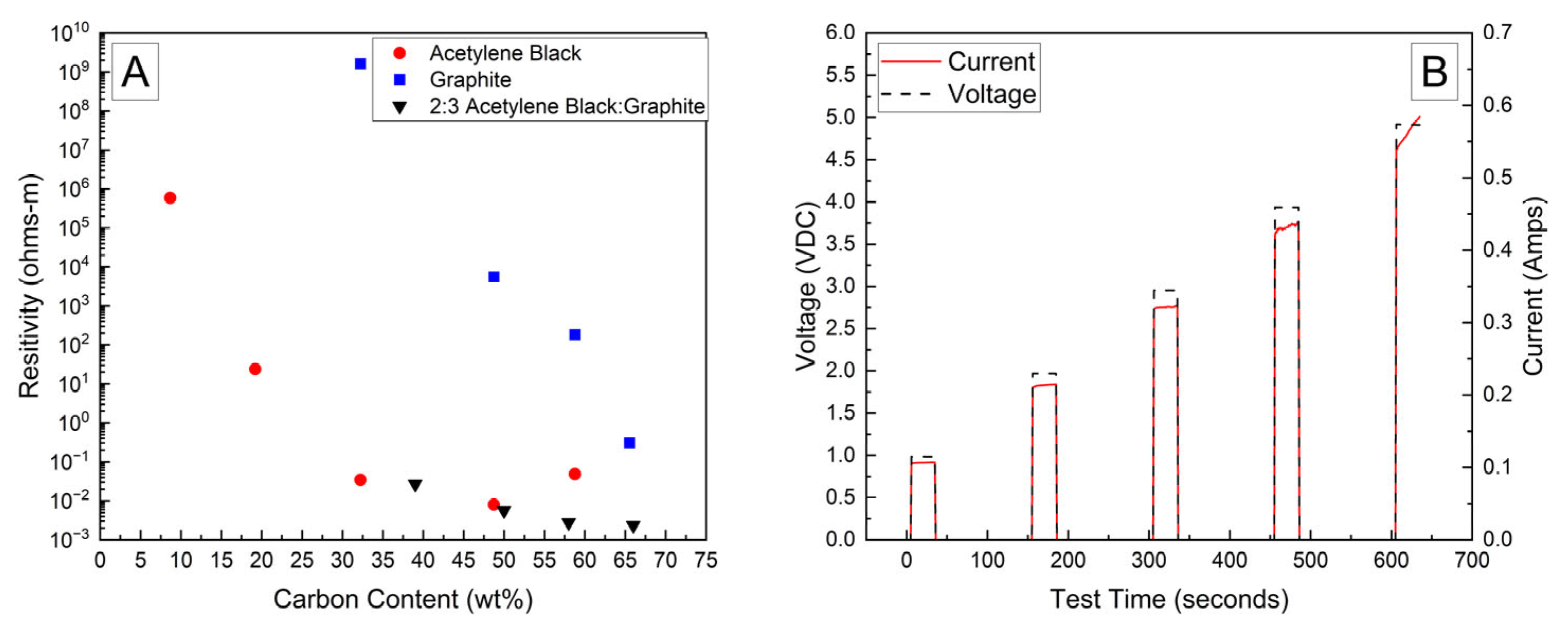
Bulk resistivities for a range of carbon contents and compositions are presented in Figure 1A. The bulk resistivity of the fully dried samples of the PVA–carbon composite loaded on filter paper containing only acetylene black or graphite were observed to decrease by several orders of magnitude with increasing carbon content; however, the resistivity of the acetylene black-containing strips was much lower than those containing only graphite due to the lower volumetric mass density of acetylene black, which corresponds to a higher volume fraction of conductive carbon at a given mass fraction. Above about 50 wt% of acetylene black, however, the resistivity was observed to increase, which was attributed to the inability of these samples to maintain structural integrity when drying. Large cracks formed in the samples containing a high weight fraction of acetylene black, preventing the formation of an electrically conductive pathway. No cracking was observed for any weight fraction of the PVA–carbon composite containing only graphite, which is attributed to the much lower tap density of the graphite powder. Higher weight fractions of acetylene black led to a greater volume fraction of carbon in the PVA–carbon composite, which above approximately 50 wt% led to cracking. A mixture of acetylene black and graphite was found to resolve the cracking issue for a composite wt% of greater than 50% carbon, resulting in the lowest observed bulk resistivity for any sample composition tested. A ratio of 2:3 acetylene black to graphite by weight was found to produce the best consistency in the prepared gel, so this ratio was applied across a range of total carbon content compositions. Bulk resistivities of 2 × 10⁻³ Ω-m were measured for strips of dried PVA–carbon gel containing 66 wt% of total carbon, which is consistent with the value expected for amorphous carbon and lower than the resistivity reported for a similar weight fraction of carbon nanotubes in PVA by Shaffer and Windle, suggesting that the dried composite is well mixed and the PVA does not significantly impede current flow [18].
A representative current response for a dried sample containing 58 wt% of carbon black and graphite in a 2:3 ratio is shown in Figure 1B. At voltages of 2 V and above, the current is observed to increase as a function of time, which becomes more prominent with increasing voltage. This behavior is attributed to a decrease in bulk resistivity due to resistive heating of the PVA–carbon composite, which is expected for both graphite and carbon black [25]. Resistive heating of the lowest bulk resistivity samples was a potential issue when applying these formulations to high-voltage and or high-power-capable batterie; therefore, lower carbon content samples were selected in these cases to achieve a safe rate of discharge. Unless otherwise indicated, the 58 wt% carbon gel composition corresponding to a bulk resistivity of 2.8 × 10⁻³ Ω-m was used for all deactivation experiments.
The voltage and temperature vs. time for a LiPo pouch cell deactivated by PVA–carbon gel is shown in Figure 2. The cell voltage is seen to drop to <0% SOC (2.5 V) after approximately 19 h. At approximately 4 h, the voltage begins to vary unrelated to the deactivation process due to the placement of the voltage sense wires, which were likely influenced by the coincident placement of the PVA–carbon gel. Minimal heating was observed by a thermocouple applied to the surface of the cell. Temperature vs. time plots of the 1.2 Ah LiPo pouch cells in response to nail penetration at a 100% SOC and after deactivation are shown in Figure 3. The deactivated cell voltage is below 2.5 V (0% SOC), which reflects a rebound from the ~0 V measured during the deactivation process shown in Figure 2. At the moment of nail penetration, both the charged and deactivated cells experience an immediate drop in cell potential to 0 V; however, only the 100% SOC cell shows a rapid rise in temperature. While the maximum temperature seen for the nail penetration of the 100% SOC LiPo cell is fairly mild at only 88 °C, the maximum heating rate exceeded 1300 °C/min, far above the rule-of-thumb heating rate of 5 °C/min attributed to thermal runaway by Doughty and Roth [26].
Cylindrical 18,650 cells were deactivated by first removing a portion of the shrink wrap covering the majority of the cell surface. Because 18,650 cells are can-negative, removing the shrink wrap significantly reduces the distance between the positively grounded header and negatively grounded can, which aids in creating the electrical connection between them. The voltage and temperature of an 18,650 LIB cell deactivated by the PVA–carbon gel is shown in Figure 4, which shows that the 18,650 cell dropped below 0% SOC (<2.5 V) within about 15 h. The same 58 wt% carbon gel composition used on the LiPo was used on the 18,650 cell, and similar to the LiPo pouch cell, only a modest temperature rise was observed. Despite using an identical gel composition and starting cell OCV, the implied current for the 18,650 discharge rate (2.5 Ah over 15 h) is much higher than that of the LiPo cell (1.2 Ah over 20 h), which may be due to variations in the cell construction and resulting internal impedance or the effective resistance of the dried gel due to the difference in electrode spacing between the two cell types. An evaluation of the 18,650 cells before and after deactivation was conducted by external heating of the cells inside of a pressure vessel. The cells were heated at a rate of 1–2 °C/min to a maximum of 180 °C. The bomb was continuously purged with nitrogen, which was connected directly to the heated sampling lines of the FTIR gas analyzer. The voltage and temperature response of the 18,650 cells inside of the pressure vessel, along with a pressure transducer reading of the pressure inside of the vessel, are presented in Figure 5A. Heating the 100% SOC 18,650 cell leads to a voltage loss attributed to activation of a current interrupt device (CID) at 130 °C. Further heating of the cell leads to an increase in measured pressure and a slight decrease in cell temperature attributed to cell venting at 157 °C. Once the cell reaches 199 °C, a rapid increase in temperature and pressure was observed, with the cell temperature reaching a maximum value of 475 °C. An identical heating profile was applied to an 18,650 cell deactivated by the PVA–carbon gel, which resulted in no signatures of thermal runaway, as shown in Figure 5B. For the deactivated cell, a small increase in pressure was observed at approximately 120 °C; however, no rapid increase in pressure or temperature followed up to the maximum experimental temperature of 180 °C. A corresponding plot of carbon dioxide (CO2), carbon monoxide (CO), methane (CH4), ethyl methyl carbonate (EMC), and hydrofluoric acid (HF), as measured by FTIR, is shown in Figure 6 for both the 100% SOC cell (Figure 6A) and PVA–carbon deactivated cell (Figure 6B). For the 100% SOC cell, an initial spike in gas concentration is observed at approximately 123 min, which corresponds with the venting observed in the pressure and temperature traces shown in Figure 5A. A much larger increase in concentration is observed for the 100% SOC cell at 160 min, which is correlated to the large increase in temperature and pressure from thermal runaway. Meanwhile, an increase in CO2 and CO gas concentrations is seen around 70 min for the 18,650 cell deactivated by the PVA–carbon gel. This is attributed to the forced venting of the electrolyte from the cell due to external heating; however CH4 and HF remain near the detection limit throughout the test. Interestingly, the presence of EMC is detected from the deactivated cell after only 60 min of heating, corresponding to a temperature of only 106 °C. This suggests that the header of the deactivated cell may have been compromised. The gas composition of the deactivated cell compared to the 100% SOC cell shows that the concentration of CO2 was reduced from 90,000 ppm to 4300 ppm, CO was reduced from 230,000 ppm to 200 ppm, CH4 was reduced from 35,000 ppm to 12 ppm, and HF was reduced from 200 ppm to 16 ppm. Concentrations of CO2, CO, CH4, and HF first appear after the cell vents (noted by a decrease in temperature and an increase in measured pressure for the 100% SOC cell). Gas concentrations in the 100% SOC cell reach a maximum value commensurate with thermal runaway, while the decomposition gases emitted from the deactivated cell rapidly drop off after venting. While CO2, CO, CH4, and HF are attributed to thermal decomposition of the electrolyte, the concentration of ethyl methyl carbonate (EMC), which is an assumed electrolyte solvent, was relatively consistent at 500 ppm from the 100% SOC cell and 280 ppm from the deactivated cell. For the 100% SOC cell, the EMC signal slowly increases and then drops off during thermal runaway, while for the deactivated cell, the EMC signal is fairly constant until the cell reaches 180 °C (the limit of the external heaters for this experiment) and begins to cool. This suggests that the EMC content is due to evaporation of the electrolyte solvent from the vented cell without significant thermal decomposition, which is also supported by the significantly lower concentrations of CO2, CO, CH4, and HF.
The voltage and temperature response for a 6 V alkaline battery deactivated by the PVA–carbon gel is shown in Figure 7. Both the voltage and capacity of the 6 V alkaline cell are significantly larger than the single cell shown in Figure 2 and Figure 4, and a correspondingly a larger temperature response is observed for the 6 V battery despite a relatively slower discharge time of approximately 25 h to reach 0% SOC (3 V lower voltage cutoff when under load). While faster discharge times are certainly possible based on the bulk resistivities demonstrated in Figure 1, an even greater temperature rise would result. When the PVA–carbon gel was removed, the voltage of the alkaline batteries rebounded to approximately 5 V; however, this corresponds to a per-cell voltage of about 1.2 V (i.e., four cells connected in series), which is near 10% SOC according to the manufacturer specifications. As alkaline cells do not undergo thermal runaway, deactivation of the 6 V alkaline battery was demonstrated via an external short circuit. Resistive heating from a short circuit can lead to fires in packaging or other combustible materials even for batteries that do not undergo thermal runaway; therefore, even relatively benign battery chemistries still present some transportation hazards when improperly handled. As-received and post-deactivation alkaline batteries were shorted through a 333 µΩ shunt to determine the short-circuit current and temperature rise in response to electrical abuse. Temperature and voltage response for the alkaline batteries subjected to external short circuit is shown in Figure 8. For both tests, the short-circuit condition was applied at an approximately 10 min test time, resulting in an immediate drop in voltage to near zero. For the as-received battery, a short-circuit current of over 2 A was briefly measured, and a corresponding rise in temperatures measured across the battery surface was observed. Thermocouples placed on the positive terminal recorded temperatures of over 200 °C, and the temperatures and short circuit current fell over approximately 2 h. For the post-deactivation battery, the current and temperature response were significantly reduced, with the short-circuit current reaching a maximum value of approximately 150 mA and the temperature increasing to only 30 °C. Like with the lithium-ion cells, reducing the state of charge of the alkaline battery has a clear beneficial effect on abuse tolerance.
A final demonstration of the PVA–carbon gel was conducted using a small power-tool battery containing three 18,650 cells connected in series. Due to the higher voltage and power capability, a relatively low carbon content of 39 wt% was used in the gel, corresponding to a bulk resistivity of 2.68 × 10⁻² Ω-m. The power-tool battery includes simple control circuitry between the external terminals and cells, which prevents operation of the battery in response to excessive temperatures and maintains appropriate cell voltages; however, no indication that this control circuit was engaged was observed, possibly because the control circuit only serves to provide a signal to a charger or tool. The temperature and voltage response of the 12 V power-tool battery is shown in Figure 9, which resulted in a complete discharge to 0% SOC (7.5 V) after approximately 35 h. Both the voltage decrease and temperature increase are low for the first 20 h of the deactivation, which is attributed first to the time required to dry the residual water content of the gel and later to the decreasing resistance with temperature shown in Figure 1 at higher voltages. Note that while the LiPo pouch cell, 18,650 lithium-ion cell, and 6 V alkaline battery deactivations were conducted in a fume hood with a high volume of air flow, the 12 V power-tool battery deactivation was conducted inside of the ARC enclosure used for abusive testing out of an abundance of caution. The ARC enclosure is sealed with very little air flow, which likely delayed the onset of significant current flow for the power-tool battery. After 25 h, the temperature recorded at the top of the power-tool battery using a thermocouple placed between the battery terminals began to rise rapidly, reaching a maximum temperature of approximately 80 °C, while a thermocouple placed on the front of the battery casing reached a maximum of about 35 °C. An infrared camera was used to confirm that heating was localized to the PVA–carbon material, while the majority of the battery remained relatively cool.
Following deactivation by the PVA–carbon gel, the power-tool batteries were dissembled, and the three 18,650 cells were removed for abusive testing via nail penetration. Upon disassembly, the voltage of the cells in the deactivated pack rebounded slightly and had voltages ranging from 1 to 2 V, similar to the value observed for the LiPO pouch cell. For comparison purposes, an untested battery was also disassembled, and individual cells were charged to 100% SOC prior to abuse testing. The voltage and temperature response of cells recovered from the 12 V power-tool battery is shown in Figure 10. Like with the previous abuse tests of 100% lithium-ion cells, a rapid increase in temperature is observed at the moment of nail penetration occurring at 10 min of test time, while the deactivated cell shows a slight decrease in temperature attributed to the nitrogen overflow from the pneumatic nail driver.
The gas analysis conducted by FTIR is shown for the recovered power-tool cells in Figure 11. Like with the 18,650 cells heated in a pressure vessel shown in Figure 6, the cells recovered from the 12 V power-tool battery generated no detectable concentrations of any of the measured gases after deactivation. CO2, CO, CH4, and DMC dropped from 45,000 ppm, 23,000 ppm, 2700 ppm, and 500 ppm to ~0 ppm after deactivation. HF was not observed for either case, presumably due to the highly reactive nature of the acid gas, which precluded detection when tested in open air, as required for the nail penetration apparatus. During nail penetration, the walls of the ARC chamber were not heated, and the gas samples were collected from the open chamber rather than directly from the sealed pressure vessel, both factors likely contributing to the undetectable HF and lower overall gas concentrations.

4. Conclusions

This paper provides a novel method to controllably and safely electrically de-energize batteries and cells of multiple chemistries and form factors. The electrical discharge of various cell types and chemistries was accomplished using a PVA–carbon gel, which resulted in the suppression of thermal runaway in lithium-ion cells in response to thermal and mechanical abuse and a significant reduction in the short-circuit current observed for an alkaline battery. Deactivation time is directly related to the composition of the PVA–carbon gel, which includes the starting water content and the total amount of conductive carbon. By selecting an appropriate carbon content, the maximum discharge rate for a given battery voltage can be predicted. Under appropriate ambient conditions that allow for the gel water content to evaporate, a decrease in cell OCV was observed within 5–10 h, and complete discharge was observed in 24–48 h. Based on the temperature and voltage response, the rate of discharge is not constant but rather increases as a function of water content in the drying gel. By reducing the hazards associated with the accidental abuse of cells and batteries during transportation, it is anticipated that many of the previously observed safety incidents involving end-of-life batteries can be avoided in the future. The operational principle of this approach is quite simple, as lowering the SOC of any battery is known to be an effective way to improve abuse tolerance. However, this technique is plausibly limited to relatively small cells and batteries, as larger batteries containing many cells in series and/or in parallel will support a much higher current depending on pack voltage and require much longer discharge times depending on pack capacity. In principle, even a relatively high voltage pack could be discharged via a high-resistance external short circuit using the formulations presented in Figure 1; however, the discharge time would likely be prohibitively long. Furthermore, additional concerns regarding the dielectric breakdown of the dried PVA–carbon composite may also arise when deactivating a high-voltage battery and are not addressed in this study. A simple unregulated discharge also leads in most scenarios to an over-discharge condition, and while this is not expected to lead to an energetic failure, over-discharge can damage cell components, which may complicate downstream materials recovery efforts. For lithium-ion batteries, Wang et al. reported that over-discharging cells to 0 V can result in copper dissolution from the anode current collector, which can complicate “direct recycling” efforts involving the rejuvenation of recycled electrode materials [27]. Swelling of pouch cells due to gas generation in the over-discharged state has also been reported, and indeed this was observed for the LiPo pouch cells in the weeks following the deactivation experiments and may have also contributed to the earlier venting behavior of the 18,650 cell shown in Figure 6 [28]. In an ideal case, battery deactivation would be conducted with supervision, and the dried PVA–carbon composite can be removed once a desired SOC is reached. At the lab scale, a small amount of distilled water is enough to re-hydrate the dried composite such that it can be wiped away with laboratory tissue, thereby breaking the electrical connection between the cell terminals and arresting further discharge. In this scenario, deactivation can be accomplished in a high-throughput manner while maintaining the highest purity of cell components as a feedstock material for downstream recycling efforts.

5. Patents

The materials and methods described in this work are disclosed in the U.S. Patent Application US18/585,046.

Author Contributions

Conceptualization, G.H.W.; methodology, G.H.W.; investigation, G.H.W., C.J. and A.G.; resources, G.H.W. and C.T.L.; data curation, G.H.W.; writing—original draft preparation, G.H.W.; writing—review and editing, G.H.W., C.J., R.A.C. and C.T.L.; visualization, G.H.W. and A.G.; supervision, G.H.W.; project administration, G.H.W.; funding acquisition, G.H.W. and C.T.L. All authors have read and agreed to the published version of the manuscript.

Funding

The authors acknowledge funding and technical support from U.S. DOT PHMSA’s Office of Hazardous Materials Safety under contract number 693JK321N000004.

Data Availability Statement

The datasets presented in this article are not readily available because of government controls on the distribution of all technical information. Requests to access the datasets should be directed to the corresponding author.

Conflicts of Interest

Author Connor Jacob was employed by the company Precise Systems Inc. The remaining authors declare that the research was conducted in the absence of any commercial or financial relationships that could be construed as a potential conflict of interest.

Abbreviations

The following abbreviations are used in this manuscript:
MDPIMultidisciplinary Digital Publishing Institute
DOAJDirectory of open access journals
PVAPolyvinyl alcohol
DDRDamaged, defective, and recalled
SOCState of charge
ARCAccelerating Rate Calorimeter
FTIRFourier Transform Infrared
PTFEPolytetrafluoroethylene
LiPoLithium polymer
CIDCurrent interrupt device
EMCEthyl methyl carbonate

References

  1. Thomas, N.; Baldauf, M.; Hohenberger, M.; Pomberger, R. Lithium-Ion Batteries as Ignition Sources in Waste Treatment Processes—A Semi-Quantitate Risk Analysis and Assessment of Battery-Caused Waste Fires. Processes 2021, 9, 49. [Google Scholar]
  2. An Analysis of Lithium-Ion Battery Fires in Waste Management and Recycling; U.S. Environmental Protection Agency Office of Resource Conservation and Recovery: Washington, DC, USA, 2021.
  3. Gavin, H.; Sommerville, R.; Kendrick, E.; Driscoll, L.; Slater, P.; Stolkin, R.; Walton, A.; Christensen, P.; Heidrich, O.; Lambert, S.; et al. Recycling Lithium-Ion Batteries from Electric Vehicles. Nature 2019, 575, 75–86. [Google Scholar]
  4. Safety Advisory Notice for the Transportation of Lithium Batteries for Disposal or Recycling; U.S. Department of Transportation Pipeline and Hazardous Materials Safety Administration: Washington, DC, USA, 2022.
  5. Zhu, M.; Zhang, S.; Chen, Y.; Zhao, L.; Chen, M. Experimental and Analytical Investigation on the Thermal Runaway Propagation Characteristics of Lithium-Ion Battery Module with Ncm Pouch Cells under Various State of Charge and Spacing. J. Energy Storage 2023, 72, 108380. [Google Scholar] [CrossRef]
  6. Chen, W.-C., C.; Li, J.-D.; Shu, C.-M.; Wang, Y.-W. Effects of Thermal Hazard on 18,650 Lithium-Ion Battery under Different States of Charge. J. Therm. Anal. Calorim. 2015, 121, 525–531. [Google Scholar] [CrossRef]
  7. Hang, W.; Chen, S.; Hong, Y.; Xu, C.; Zheng, Y.; Jin, C.; Chen, K.; He, Y.; Feng, X.; Wei, X.; et al. Thermal Safety Boundary of Lithium-Ion Battery at Different State of Charge. J. Energy Chem. 2024, 91, 59–72. [Google Scholar]
  8. Tapesh, J.; Azam, S.; Lopez, C.; Kinyon, S.; Jeevarajan, J. Safety of Lithium-Ion Cells and Batteries at Different States-of-Charge. J. Electrochem. Soc. 2020, 167, 140547. [Google Scholar]
  9. Karmakar, A.; Zhou, H.; Vishnugopi, B.S.; Jeevarajan, J.A.; Mukherjee, P.P. State-of-Charge Implications of Thermal Runaway in Li-Ion Cells and Modules. J. Electrochem. Soc. 2024, 171, 010529. [Google Scholar] [CrossRef]
  10. Alexis, P.; Paolella, A.; Dubé, J.; Champagne, D.; Mauger, A.; Zaghib, K. State of Charge Influence on Thermal Reactions and Abuse Tests in Commercial Lithium-Ion Cells. J. Power Sources 2018, 399, 392–397. [Google Scholar]
  11. Feng, X.; Zheng, S.; Ren, D.; He, X.; Wang, L.; Cui, H.; Liu, X.; Jin, C.; Zhang, F.; Xu, C.; et al. Investigating the Thermal Runaway Mechanisms of Lithium-Ion Batteries Based on Thermal Analysis Database. Appl. Energy 2019, 246, 53–64. [Google Scholar] [CrossRef]
  12. Yu, D.; Huang, Z.; Makuza, B.; Guo, X.; Tian, Q. Pretreatment Options for the Recycling of Spent Lithium-Ion Batteries: A Comprehensive Review. Miner. Eng. 2021, 173, 107218. [Google Scholar] [CrossRef]
  13. Mikita, R.; Suzumura, A.; Kondo, H. Battery Deactivation with Redox Shuttles for Safe and Efficient Recycling. Sci. Rep. 2024, 14, 3448. [Google Scholar] [CrossRef] [PubMed]
  14. Martin, G.; Mönnighoff, X.; Horsthemke, F.; Kraft, V.; Winter, M.; Nowak, S. Extraction of Lithium-Ion Battery Electrolytes with Liquid and Supercritical Carbon Dioxide and Additional Solvents. RSC Adv. 2015, 5, 43209–43217. [Google Scholar]
  15. Mu, D.Y.; Liang, J.Q.; Zhang, J.; Wang, Y.; Jin, S.; Dai, C.S. Exfoliation of Active Materials Synchronized with Electrolyte Extraction from Spent Lithium-Ion Batteries by Supercritical CO2. Chemistryselect 2022, 7, e202200841. [Google Scholar] [CrossRef]
  16. Velázquez-Martínez, O.; Valio, J.; Santasalo-Aarnio, A.; Reuter, M.; Serna-Guerrero, R. A Critical Review of Lithium-Ion Battery Recycling Processes from a Circular Economy Perspective. Batteries 2019, 5, 68. [Google Scholar] [CrossRef]
  17. Roberto, S.; Shaw-Stewart, J.; Goodship, V.; Rowson, N.; Kendrick, E. A Review of Physical Processes Used in the Safe Recycling of Lithium Ion Batteries. Sustain. Mater. Technol. 2020, 25, e00197. [Google Scholar]
  18. Shaffer, M.S.P.; Windle, A.H. Fabrication and Characterization of Carbon Nanotube/Poly(Vinyl Alcohol) Composites. Adv. Mater. 1999, 11, 937–941. [Google Scholar] [CrossRef]
  19. Juey, Y.M.; Mubarak, N.M.; Khalid, M.; Abdullah, E.C.; Jagadish, P. Synthesis of Polyvinyl Alcohol (Pva) Infiltrated Mwcnts Buckypaper for Strain Sensing Application. Sci. Rep. 2018, 8, 17295. [Google Scholar]
  20. Jurgis, B.; Vinslovait, A. Investigation of Electroconductive Films Composed of Polyvinyl Alcohol and Graphitized Carbon Black. Mater. Res. Bull. 2003, 38, 1437–1447. [Google Scholar]
  21. Gao, Y.; Fang, X.; Tran, D.; Ju, K.; Qian, B.; Li, J. Dielectric Elastomer Actuators Based on Stretchable and Self-Healable Hydrogel Electrodes. R. Soc. Open Sci. 2019, 6, 182145. [Google Scholar] [CrossRef]
  22. Han, J.; Wang, H.; Yue, Y.; Mei, C.; Chen, J.; Huang, C.; Wu, Q.; Xu, X. A Self-Healable and Highly Flexible Supercapacitor Integrated by Dynamically Cross-Linked Electro-Conductive Hydrogels Based on Nanocellulose-Templated Carbon Nanotubes Embedded in a Viscoelastic Polymer Network. Carbon 2019, 149, 1–18. [Google Scholar] [CrossRef]
  23. Zheng, W.; Li, Y.; Xu, L.; Huang, Y.; Jiang, Z.; Li, B. Highly Stretchable, Healable, Sensitive Double-Network Conductive Hydrogel for Wearable Sensor. Polymer 2020, 211, 123095. [Google Scholar] [CrossRef]
  24. Casassa, E.Z.; Sarquis, A.M.; Van Dyke, C.H. The Gelation of Polyvinyl Alcohol with Borax: A Novel Class Participation Experiment Involving the Preparation and Properties of a “Slime”. J. Chem. Educ. 1986, 63, 57. [Google Scholar] [CrossRef]
  25. Buerschaper, R.A. Thermal and Electrical Conductivity of Graphite and Carbon at Low Temperatures. J. Appl. Phys. 1944, 15, 452–454. [Google Scholar] [CrossRef]
  26. Doughty, D.H.; Roth, E.P. A General Discussion of Li Ion Battery Safety. Electrochem. Soc. Interface 2012, 21, 37–44. [Google Scholar]
  27. Wang, Y.; Du, H.; Zhao, Y.; Kang, Y.; Zhang, J.; Xu, J.; Huang, Y.; Jia, T.; Chen, Z.; Tavajohi, N.; et al. Physical Discharge of Spent Lithium-Ion Batteries Induced Copper Dissolution and Deposition. ChemSusChem 2025, 18, e202401458. [Google Scholar] [CrossRef]
  28. Hossein, M.; Howard, J.N. Effects of Overdischarge on Performance and Thermal Stability of a Li-Ion Cell. J. Power Sources 2006, 160, 1395–1402. [Google Scholar]
Figure 1. Bulk resistivity vs. carbon content in dried PVA–carbon strips (A) and voltage and current vs. time for dried strip of PVA–carbon gel (B).
Batteries 11 00201 g001
Figure 2. Photograph of LiPo cell with PVA–carbon gel applied to terminals (A), and voltage and temperature vs. time for LiPo cell deactivated by PVA–carbon gel (B).
Batteries 11 00201 g002
Figure 3. Nail penetration of 1.2 Ah LiPo pouch cells at 100% SOC (A) and after deactivation by PVA–carbon gel (B).
Batteries 11 00201 g003
Figure 4. Photograph of 18,650 cell with PVA–carbon gel applied to terminals (A), and voltage and temperature vs. time for 18,650 cell deactivated by PVA–carbon gel (B).
Batteries 11 00201 g004
Figure 5. Voltage, pressure, and temperature vs. time for 18,650 cells at 100% SOC (A) and after deactivation by PVA–carbon gel (B) heated to failure inside of a pressure vessel.
Batteries 11 00201 g005
Figure 6. FTIR gas analysis of 18,650 cells at 100% SOC (A) and after deactivation by PVA–carbon gel (B) heated to failure inside of a pressure vessel.
Batteries 11 00201 g006
Figure 7. Photograph of 6V alkaline battery with PVA–carbon gel applied to terminals (A) and voltage and temperature of a 6V alkaline battery deactivated by PVA–carbon gel (B).
Batteries 11 00201 g007
Figure 8. Voltage, temperature, and shunt current of 6 V alkaline battery during external short circuit before (A) and after (B) deactivation by PVA–carbon gel.
Batteries 11 00201 g008
Figure 9. Photograph of 12 V power-tool battery with PVA–carbon gel applied to terminals (A), voltage and temperature of a 12 V power-tool battery deactivated by PVA–carbon gel (B), and infrared images of the 12 V power-tool battery during deactivation (C).
Batteries 11 00201 g009
Figure 10. Nail penetration of cells recovered from a 12 V power-tool battery at 100% SOC (A) and after deactivation by PVA–carbon gel (B).
Batteries 11 00201 g010
Figure 11. FTIR gas analysis of cells recovered from a 12 V power tool battery at 100% SOC (A) and after deactivation by PVA–carbon gel (B) during nail penetration.
Batteries 11 00201 g011
Table 1. Cell types deactivated by PVA/carbon gel.
Cell or Battery TypeCapacity
(Ah)
0–100% SOC
Voltage Window (VDC)
Abuse
Method
Lithium-polymer (LiPo) pouch cell1.22.5–4.2Nail penetration
Lithium-ion 186502.52.5–4.2Heat to failure with FTIR gas analysis
Alkaline lantern battery183–6External short circuit
Lithium-ion power-tool battery2.07.5–12Nail penetration of recovered cells with FTIR gas analysis
Disclaimer/Publisher’s Note: The statements, opinions and data contained in all publications are solely those of the individual author(s) and contributor(s) and not of MDPI and/or the editor(s). MDPI and/or the editor(s) disclaim responsibility for any injury to people or property resulting from any ideas, methods, instructions or products referred to in the content.

