Article

Nanoporous Carbon Coatings Direct Li Electrodeposition Morphology and Performance in Li Metal Anode Batteries

by
Katharine L. Harrison
1,*,†,
Subrahmanyam Goriparti
1,‡,
Daniel M. Long
2,§,
Rachel I. Martin
1,
Benjamin Warren
1,
Laura C. Merrill
1,
Matthaeus A. Wolak
1,‖,
Alexander Sananes
1,¶ and
Michael P. Siegal
1
1
Nanoscale Sciences Department, Sandia National Laboratories, Albuquerque, NM 87123, USA
2
Center for Integrated Nanotechnology, Sandia National Laboratories, Albuquerque, NM 87123, USA
*
Author to whom correspondence should be addressed.
Current address: National Renewable Energy Lab, Golden, CO 80401, USA.
Current address: General Motors, Warren, MI 48092, USA.
§
Current address: NBACC, Ft. Detrick, MD 21702, USA.
Current address: Northrop Grumman, Linthicum Heights, MD 21240, USA.
Current address: Physical Sciences Inc., Andover, MA 01810, USA.
Batteries 2025, 11(1), 10; https://doi.org/10.3390/batteries11010010
Submission received: 1 December 2024 / Revised: 18 December 2024 / Accepted: 24 December 2024 / Published: 27 December 2024

Abstract

:
Li metal anodes could significantly improve battery energy density. However, Li generally electrodeposits in poorly controlled morphology, leading to safety and performance problems. One factor that controls Li anode performance and electrodeposition morphology is the nature of the electrolyte–current collector interface. Herein, we modify the Cu current collector interface by depositing precisely controlled nanoporous carbon (NPC) coatings using pulsed laser deposition to develop an understanding of how NPC coating density and thickness impact Li electrodeposition. We find that NPC density and thickness guide Li morphological evolution differently and dictate whether Li deposits at the NPC-Cu or NPC-electrolyte interface. NPC coatings generally lower overpotential for Li electrodeposition, though thicker NPC coatings limit kinetics when cycling at a high rate. Lower-density NPC enables the highest Coulombic efficiency (CE) during calendar aging tests, and higher-density NPC enables the highest CE during cycling tests.

Graphical Abstract

1. Introduction

Li-ion battery demand is growing rapidly owing to widespread applications ranging from portable electronics to electric vehicles. Higher energy density batteries are desired for many applications, and Li metal anodes could increase energy density significantly due to 10x higher theoretical gravimetric capacity than state-of-the-art graphite anodes. Conventional graphite anodes undergo Li+ insertion and de-insertion to reversibly store charge. In contrast, Li metal anodes store charge by converting back and forth between Li+ and metallic deposits on the current collector, generating or consuming electrons in the process. However, Li metal anodes suffer from performance and safety problems owing to uncontrolled morphology, resulting in high-aspect-ratio metallic features—such as dendrites—that can puncture the separator and short-circuit the cell. Many strategies have been proposed to improve Li morphology, including (1) strategic cycling protocols [1,2], (2) electrolyte additives [3,4,5,6], (3) designer electrolytes [1,7,8,9,10], (4) solid-state electrolytes [11,12,13,14,15], (5) improved separator designs [16,17], (6) applied pressure [18,19,20], (7) ex-situ coatings (“artificial solid electrolyte interphases” or ASEIs) [20,21,22,23,24,25,26,27,28,29,30,31,32,33,34,35,36,37], and (8) 3D porous host structures [38,39,40,41,42,43,44,45,46,47,48,49,50,51,52,53].
ASEI coatings show promise for improving Li cycling morphology and performance [20,21,22,23,24,25,26,27,28,29,30,31,32,33,34,35,36,37]. The term ASEI implies that it replaces the innate SEI that forms from electrolyte reduction at low anode potentials. Ideal ASEIs would be made of thin, ionically conducting, and electrically insulating materials that prevent Li-electrolyte reactions by directing Li electrodeposition below the ASEI [20,31]. Coatings can also direct the nucleation and growth of the Li, such that Li may electroplate on top rather than below the coating [29]. In that case, the coating does not serve as a protective barrier, does not need to be electronically insulating, and does not really act as an ASEI; regardless, we use the term ASEI to distinguish thin coatings from 3D porous structures. The differences in morphology resulting from ASEI coatings can impact Li cycling morphology and, ultimately, cycling or calendar aging performance [29]. Because ASEI coatings are thin, they can break over extended cycling [29].
In contrast to ASEIs, 3D porous host structures differ in that they are usually thicker, conductive coatings such as carbon or metals with pore space, within which Li nucleates and grows [38,39,40,41,42,43,44,45,46,47,48,49,50,51,52,53]. This conductive scaffold increases the surface area of the electrode and spreads the current out over a larger area. The resulting lower effective current density enables more control over Li metal electrodeposition and can lead to improved cycling and morphological evolution. This approach theoretically also builds in the volume needed to incorporate plated Li metal within the scaffold rather than growing Li on a bare current collector and partially shrinking it back with each cycle. However, in practice, electrodepositing Li in porous structures does not necessarily fully constrain the volume change [44].
Many materials have been used as ASEIs and 3D porous hosts with various advantages and disadvantages. However, carbon is attractive for ASEI coatings and 3D porous hosts because it is lightweight and is commonly used in other parts of the cell (e.g., as a conductive additive in cathodes and graphite anodes), which means it is at least reasonably compatible with electrolytes and potential windows. Carbon can also be highly tuned or functionalized with various chemical moieties to alter its lithiophilicity [46,54,55]. Lithiophilicity describes the affinity of a surface to nucleate Li, which, in turn, affects morphological evolution. Furthermore, edge-rich graphene sheets have been shown to enable lithiophilicity [51].
There are many papers that demonstrate carbons as thin ASEI coatings or host structures [31,32,33,34,35,36,37,41,42,43,44,45,46,47,48,49,50,51,52,53]. Thin ASEIs add minimal mass and volume to the cell and, therefore, may enable better morphological control of Li metal while still maintaining high gravimetric and volumetric energy density, as long as the coatings are much thinner than the Li metal deposits. However, low ASEI surface area renders them incapable of controlling Li morphology by lowering the effective current density, and they can break up over extended cycling [29]. ASEI coatings do not build in space for volume change like 3D hosts, so they cannot accommodate the massive volume changes that Li cycling imparts on cells, which eventually leads to mechanical and chemical degradation. However, if the thickness and weight of the 3D host are significant, they can negate the benefits of Li compared to graphite anodes, particularly because the volumetric capacity improvement of Li relative to graphite is much smaller than the gravimetric capacity improvement [56]. Therefore, the entire thickness and mass of the anode should be considered to understand whether there is a net benefit to including 3D hosts or ASEIs with Li metal anodes.
To minimize mass and volume penalties of the host relative to the Li metal, we focus in this work on studying relatively thin coatings of graphene-like material and analyzing the impact of those coatings on Li metal anode performance and morphology. We grow highly tunable nanoporous carbon (NPC) coatings by pulsed laser deposition (PLD) [57,58] with precise control over the density and thickness of the coatings to understand the impacts of these ASEI carbon properties on Li cycling. Previous Raman spectra of NPC films reveal features typical of high sp2-content amorphous carbon films, indicating the existence of very small carbon atom clusters, regardless of the NPC density [57]. The primary sp2 bonding is consistent with high-resolution transmission electron microscopy (TEM) images, which reveal small nm-sized clusters made up of a few graphene sheets [58]. Lower-density NPC exhibits expanded spacing between graphene layers and higher porosity between nanometric domains [58]. Furthermore, Brunauer, Emmett, and Teller (BET) measurements show that surface area increases significantly with decreasing density, which is consistent with porosity increasing with decreasing density [59]. In the current study, we focus on 0.8 g/cm3 and 2.0 g/cm3 NPC. 0.8 g/cm3 NPC has been shown previously to exhibit a BET surface area of about 1400 m2/g [59], which is similar to mesoporous carbons [60]. While 2.0 g/cm3 NPC was not specifically tested in previous work, extrapolation of the trend from other densities suggests the surface area would be <400 m2/g [59]. While this is a rough estimate, it is certain that the surface area of 2.0 g/cm3 NPC would be significantly lower than 0.8 g/cm3 NPC. The current study differs from previous demonstrations of similar PLD NPC as an ion insertion host for Li+ [61], Na+ [62], and Mg2+ [59]; in prior work, these ions are inserted into the NPC lattice or stored on NPC edge groups rather than ions being reduced to bulk metallic Li, as is studied here.
Because Li+ can be inserted into NPC, we hypothesize it should act as a lithiophilic coating that may improve nucleation and growth of Li metal relative to lithiophobic Cu. We deposit NPC on Cu current collectors at two densities and two coating loadings to show how these parameters impact theoretical capacity, Li electrodeposition morphology, rate performance, cycling performance, and calendar aging. We find that NPC-coated Cu generally leads to lower overpotential for Li electrodeposition than bare Cu. Despite this, nucleation density is relatively low for NPC-coated Cu samples, even though NPC is lithiophilic. The density and the thickness of the NPC impact whether Li electrodeposition occurs at the Cu-NPC or the NPC-electrolyte interface.

2. Materials and Methods

2.1. NPC Deposition and Characterization

60 μm thick, 12 mm diameter Cu discs were etched with 1.2 M HCl for 10 min to remove the oxide layer and create a repeatable Li electrodeposition/electrodissolution surface. After etching, the Cu discs were rinsed with deionized water and acetone and were immediately transferred to a glove box. The Cu discs were removed from the glove box immediately before NPC deposition to control and minimize re-oxidation before loading into the PLD system.
Prior to depositing NPC, three Cu discs were mounted onto a sample holder and placed in a vacuum chamber 3.0 inches opposite a 1.0-inch diameter pyrolytic graphite target. A base pressure of 10−7 Torr was reached to remove atmospheric contaminants, and the chamber was backfilled with Ar gas to reach operating pressures between 10–160 mTorr. The pyrolytic graphite target was rotating during ablation using a 248 nm KrF excimer laser. The energy density of the laser was set to just above the ablation limit at ~1.5 J/cm2. The addition of Ar during NPC growth attenuates the kinetic energy of the ablated carbon species, resulting in lower mass densities with increasing Ar pressure while also increasing the overall film thickness. Lower mass densities result in increased pore sizes and interplanar spacing between graphene sheet fragments, thus increasing the NPC surface area [57,58,59,61,62]. Figure S1 shows the calibration curve between Ar pressure and mass density of the deposited NPC for the conditions studied herein (which change with factors like sample-to-target distance and laser power).
Two carbon mass densities (0.8 and 2.0 g/cm3) and two carbon loadings (0.01 ± 0.002 mg/cm2 and 0.1 ± 0.02 mg/cm2) were used in this study. Because the same two NPC mass loadings were used with two different NPC mass densities, the coating thicknesses varied such that 0.8 g/cm3 NPC coatings were thicker (0.125 and 1.25 μm) and 2.0 g/cm3 NPC coatings were thinner (0.05 and 0.5 μm) at either given NPC mass loading. Figure S2 shows SEM cross-sections of representative NPC coatings with varied thickness and density.
The energy density uniformity across the laser beam profile was calibrated and verified before depositions were performed to ensure an even distribution of graphene sheet fragments at a given density throughout the sample. Non-uniformity in the laser beam profile can lead to high-energy ablation of the graphite target at local hot spots, which (a) leads to uncontrolled regions of high-density NPC and (b) causes graphitic microparticles to be ablated and mixed with the low-energy graphene sheets; both will affect the overall mass density uniformity and composition within the sample at the nanoscale. An aperture was installed at the exit window of the laser to mask off low-energy parts of the beam and to achieve optimal beam energy density profile uniformity. Additionally, a high-resolution energy density laser beam energy distribution curve was created using a small slit and tracking the energy density while systematically moving the slit along the beam profile. The energy density distribution along the beam profile was checked at regular intervals to ensure sample quality and was only allowed to deviate by a maximum of 5% from the average value. Adjustment of the front and back mirrors of the laser was used to correct the energy distribution of the laser profile. The transparency of the optical beam path, which includes the focal lens, the window into the vacuum chamber, and a protective glass slide inside of the vacuum chamber, was considered when performing PLD, as the deposition relies heavily on the laser energy being just above the ablation limit of the graphite target. The transparency of the optics was tested every few depositions to ensure an accurate laser energy for ablation was used.
The NPC density was calculated by depositing onto large test Si substrates at varying Ar pressure conditions. The weight of the Si was measured before and after the deposition using a microbalance with accuracy in the tenths of micrograms and then measuring the sample area. The Si was cleaved for cross-sectional imaging using a scanning electron microscope (SEM) to determine the NPC thickness (see Figure S2). The density was then calculated based on the change in weight of the Si with the addition of the NPC per unit volume of the NPC on the Si. There is an uncertainty of 2.5% in the thickness measurements due to slight variations in thickness across the sample and the resolution of the SEM. The overall uncertainty of the density of the NPC coatings is 6% after taking into account the NPC thickness uncertainty and the uncertainties in sample weight and area.

2.2. Coin Cell Fabrication and Testing

CR2032 coin cells were fabricated with NPC-coated Cu working electrodes in an Ar-filled glove box with water and oxygen levels < 2 ppm. A total of 50 μm Li laminated to Cu (Albermarle, Kings Mountain, NC, USA) was used for counter electrodes, and the cells were cycled in 40 μL of 1 M Li bis fluorosulfonyl imide (LiFSI) in 1,3-dioxolane/1,2-dimethoxyethane (DOL/DME) electrolyte with 1% LiNO3. The LiFSI (Oakwood Chemical, Estill, SC, USA) and LiNO3 (Sigma-Aldrich, St. Louis, MO, USA) salts were dried at 100 °C for at least 24 h under vacuum in a heated antechamber in the glove box. DOL (Sigma Aldrich, St. Louis, MO, USA, anhydrous, 75 ppm butylated hydroxytoluene as inhibitor) and DME (Sigma-Aldrich, St. Louis, MO, USA, anhydrous) were dried over activated alumina (Alpha Aesar, Ward Hill, MA, USA, Super Activated, Neutral, Grade I). The activated alumina was dried in stages, with the final stage consisting of drying under vacuum in the heated antechamber glove box at 200 °C for 24–48 h. Then, vials were filled with about a 1:3–1:4 ratio of dried activated alumina to solvent, and the vials were left in a glove box for at least 24 h before making the electrolyte. The LiFSI was mixed in 1:1 DOL:DME by volume and stirred for at least 2 h at 45 °C. Then 1% LiNO3 by weight was added to the solution, which was stirred for 2 h before making cells. Also, 1 M Li bis(trifluoromethanesulfonyl)imide (LiTFSI, Ossila, Sheffield, UK) was substituted for LiFSI in a few tests after drying at 100 °C in the heated glove box antechamber. Two Celgard 2325 separators (Charlotte, NC, USA) were included between the electrodes, and a Hohsen wave spring (Osaka, Japan) with 1.4 mm of spacers was used to apply pressure to the stack.
Coin cells were rested for 24 h before testing them on Arbin battery cyclers (College Station, TX, USA) at 0.5 or 2 mA/cm2 to 1 mAh/cm2 during electrodeposition based on the area of the 12 mm diameter NPC-coated Cu discs. A 1 V potential limit was used to terminate the electrodissolution step. To prevent excessive capacities in the event of a short circuit, the charge capacity was also limited to 2 mAh/cm2 (double the electrodeposition capacity). Some cells were cycled continuously, and some were cycled with 24 h intermittent calendar aging rest steps implemented every 5th cycle, as is described in more detail throughout.

2.3. Characterization of Li Electrodeposits

After the first Li electrodeposition, coin cells were disassembled using a Hohsen de-crimping tool (Osaka, Japan). The NPC-coated Cu working electrodes with Li electroplated on them were removed from cells in an Ar-filled glove box, washed with dry DME for 30 s, and then were transferred in bags and jars to a glove bag that was sealed around a scanning electron microscope (SEM, FEI NovaNano SEM 230, Hillsboro, OR, USA). The glove bag was purged until the humidity dropped to <1% before transferring samples to the SEM and collecting top-down images at room temperature.
To further characterize the Li deposits, a Ga+-focused ion beam (FIB) was used under cryogenic conditions to cross-section and image a subset of the samples with cryogenic SEM. Cryogenic conditions were used to prevent heating and beam-induced damage that could distort the sensitive Li samples. Samples were washed to remove excess electrolyte by soaking them for 30 s in dry DME and then drop cleaning with 1 mL additional DME while holding the sample at a 45o angle. The samples were secured to SEM stubs in an Ar-filled glove box and were transferred to a high vacuum before cooling to −150 °C in a Leica VCT500 transfer shuttle (Wetzlar, Germany). The samples were coated with 10 nm Pt in a Leica ACE600 system (Wetzlar, Germany) to improve conductivity, and then the samples were transferred into a Thermo Fisher Scientific Scios 2 FIB/SEM system (Waltham, MA, USA). The samples were kept cool with a Leica cryogenic sample stage (Wetzlar, Germany) cooled to −150 °C. FIB cross-section trenches were cut using a 16 kV, 1.5 nA beam and then were polished with a 0.5 nA beam. High-resolution images were collected at 5 kV with 50 pA current. Energy dispersive X-ray spectroscopy (EDS) maps were also collected at 5 kV and 1.5 nA using an Octane Elite EDAX EDS detector (Gatan, Pleasanton, CA, USA).

3. Results

3.1. Theoretical Li Capacity with NPC Coating Mass/Volume Included

This study explores the role of NPC density and thickness on Li metal electrodeposition and electrodissolution behavior. We carefully selected the NPC thicknesses to ensure that they would not greatly degrade the theoretical energy density of Li metal anodes. Many studies have shown that carbon favorably impacts Li metal cycling and controls morphology [31,38,39,40,41,42,43,44,45,46,51,54,55]. While a handful of studies employ very thin (<2 μm) carbon layers to guide Li growth [31], many more employ thick carbon (tens-hundreds of μm) relative to the amount of Li being cycled [38,39,40,41,42,43,44,45,46,47,48,49,50,51,52,53]. If the amount of carbon is not carefully minimized, coatings or 3D scaffolds may negate the energy density benefit of using Li metal anodes instead of graphite.
Table 1 summarizes the NPC coatings tested herein and shows that even relatively thin carbon layers have a significant impact on the theoretical volumetric and gravimetric capacity of Li metal anodes. The amounts of deposited NPC were chosen to be relatively small fractions of the theoretical plated Li metal thickness (1–26%) and mass (4–39%) in this study so that the NPC does not significantly reduce the capacity to the extent that it negates the capacity improvements relative to conventional graphite. The theoretical Li gravimetric and volumetric capacities are 3860 mAh/g and 2061 mAh/cm3, respectively, compared to graphite theoretical capacities of 372 mAh/g and 841 mAh/cm3. Because graphite anodes are typically porous, it is also reasonable to compare these numbers to an estimate for practical porous graphite electrodes, which we have previously estimated to be ~528 mAh/cm3 [56]. Table 1 shows that all NPC coatings used here are sufficiently thin that they theoretically enable Li cycling with significantly higher gravimetric energy density than graphite, even after accounting for the NPC mass and volume. However, when 1 mAh/cm2 of Li metal is plated on the higher loading NPC coatings (0.1 mg/cm2), the theoretical volumetric energy density drop is significant, illustrating that coating and scaffold thicknesses need to be considered. In contrast, many papers employ thick carbon structures (tens-hundreds of μm) or do not report the carbon thickness that is used, which often leads to very impressive performance but may not be practical from an energy density perspective [41,42,43,44,45,46,47,48,49,50,51,52,53]. These calculations demonstrate that carbon coatings and scaffolds used to guide morphology must be very thin relative to the Li capacity to ensure that Li anodes maintain higher capacity than graphite.
It should be noted that 1 mAh/cm2 capacity is equivalent to ~4.9 μm of densely plated Li, but Li generally plates in a porous morphology, so the thickness of the Li is generally greater than the fully dense limit [29,30,56,63]. Consequently, it is unlikely that the plated Li volumetric capacity would reach the theoretical limits in Table 1 even without NPC, making it even more important that additional mass and volume of carbon be included. The theoretical volumetric energy density described in Table 1 is based on the Li thickness if it were to electrodeposit in a dense morphology, and Li was assumed to be fully dense for the purposes of determining the impact of NPC thickness on energy density. Also important is that we assume all capacity during cycling is associated with Li metal electrodeposition with no contribution from Li+ insertion into the NPC or parasitic reactions that may contribute to SEI formation. We have previously demonstrated that Li+ inserts into NPC reversibly, but NPC does not delithiate significantly below the 1 V limit used to terminate the Li electrodissolution step in this work [61]; therefore, we expect Li+ to insert into NPC and contribute to capacity before the first Li electrodeposition but not contribute to capacity thereafter.
In addition to varying NPC mass loading, we also vary the NPC density (0.8 and 2.0 g/cm3) to understand how the nature of the carbon guides Li cycling. As shown previously, NPC consists of largely sp2 graphene-like carbon with nanometric domains of randomly oriented few-layer stacked graphene sheets that support ion insertion, with NPC density inversely related to porosity and surface area [57,58,59,61,62]. Because the mass is constant when density is varied, the NPC coatings with lower density are also thicker than those with higher density. Therefore, the impact of the NPC coatings on gravimetric capacity is the same for high- and low-density NPC, but lower-density NPC more significantly impacts the practical volumetric capacity than higher-density NPC.

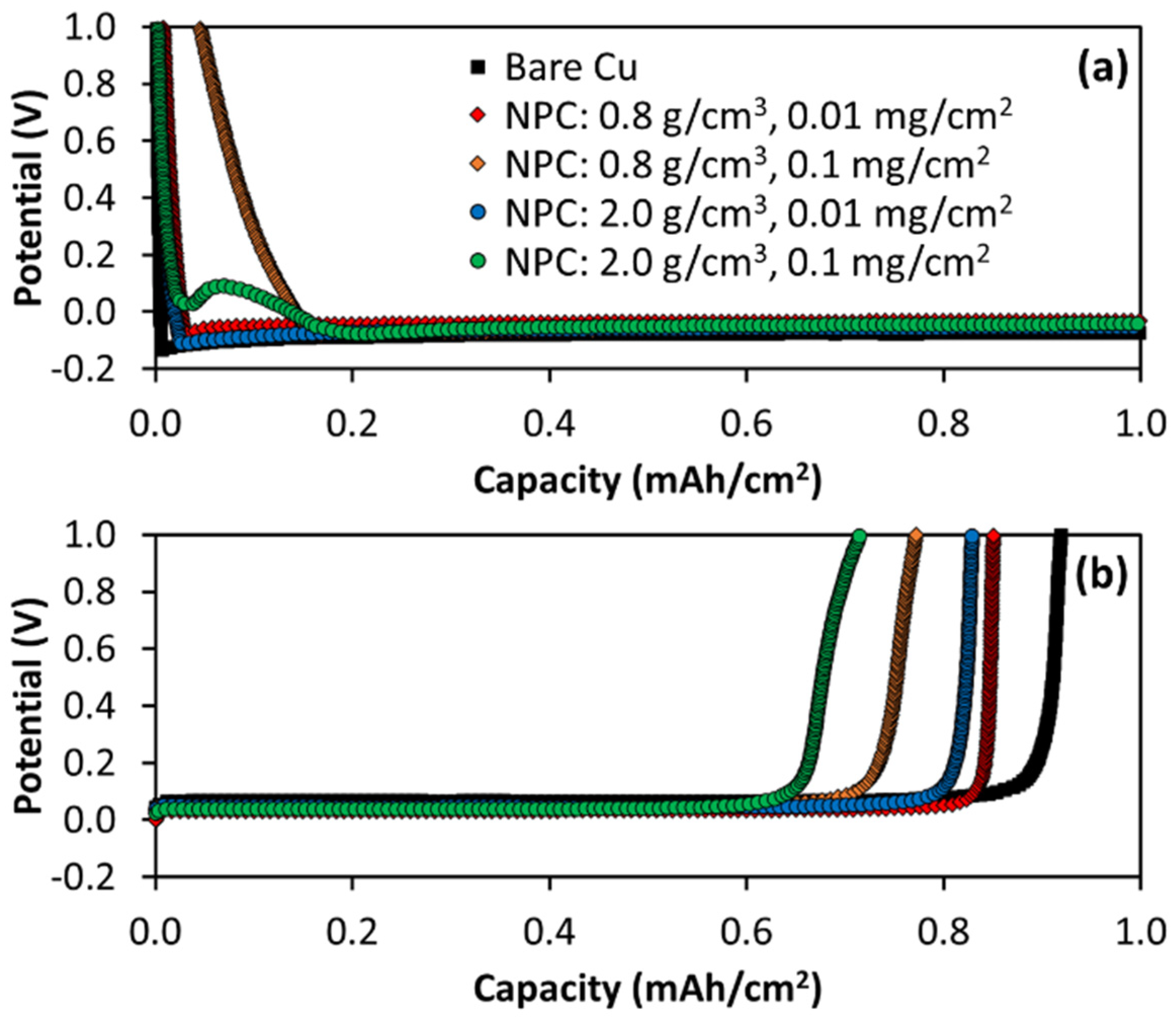
3.2. First Cycle Li Electrodeposition on NPC-Coated Cu

First-cycle Li electrodeposition curves on bare Cu and NPC-coated Cu current collectors with varied NPC thicknesses and densities are shown in Figure 1, and the same data are presented with varied scales in Figure S3. These data were collected in coin cells with Li metal counter electrodes and 1 M LiFSI in 1:1 DOL:DME + 1% LiNO3 electrolyte. As expected from the literature [64], early experiments showed better CE and Li cycling stability on bare Cu with the LiNO3 additive than without it, so LiNO3 was used throughout the study. The NPC density and mass loading impact the first Li electrodeposition signatures. As we have shown previously, Li+ inserts into NPC over a range of potentials below 1.6 V versus Li/Li+ [61]. Compared to electrodepositing on bare Cu, where the potential drops below 0 V almost immediately, the samples with NPC coatings exhibit sloping voltages due to Li+ insertion into the NPC. Due to ~10x more NPC in the 0.1 mg/cm2 than 0.01 mg/cm2 NPC loading cells, higher mass loading NPC exhibits larger sloping, irreversible capacity (~0.17 mAh/cm2, ~1500 mAh/g_NPC)—before the subsequent Li electrodeposition plateau—than lower mass loading NPC (~0.02 mAh/cm2, ~2000 mAh/g_NPC). The lithiation capacities of NPC vary with both density and thickness, with higher gravimetric capacities generally associated with lower density and thinner films [61].
Li+ insertion into 0.8 g/cm3 NPC with 0.1 mg/cm2 loading causes a gradual potential decrease with increasing capacity. Though the 2.0 g/cm3, 0.1 mg/cm2 NPC exhibits similar lithiation capacity before the Li metal electrodeposition plateau, the potential drops much more rapidly and increases after an initial dip and then plateaus. While the location and the size of the initial dip vary slightly in the 2.0 g/cm3 NPC samples with 0.1 mg/cm2 loading, as shown in Figure S4, the dip is consistently observed for only the high-loading, high-density samples. This dip, resembling a nucleation overpotential, is likely due to kinetic limitations associated with slower Li+ transport when lithiating the thick and dense NPC. These NPC coatings are deposited without a binder, so there is little porosity in the 2.0 g/cm3 NPC, given that the density is close to pristine graphite. It is likely that Li+ transports largely by solid-state diffusion through the dense NPC layer from the NPC-electrolyte interface in the first NPC lithiation, leading to a kinetic barrier and large overpotential to initiate this process. As will be discussed near the end of the paper, the dip and Li insertion plateau associated with the 2.0 g/cm3, 0.1 mg/cm2 NPC coating occurs at a lower potential when a higher current density is employed, further suggesting this feature is related to a kinetic barrier. Finally, this dip is not observed when NPC is cycled more slowly as an ion-insertion anode [61] rather than using it as a coating for Li metal cycling, and all densities exhibit similarly shaped potential versus capacity curves on the first lithiation. While we have not measured Li+ conductivity in varied density NPC, these observations all suggest that Li+ insertion is rate limited in 2.0 g/cm3 NPC under the conditions in the current study.
No plateau is observed when lithiating 2.0 g/cm3 NPC with a 0.01 mg/cm2 loading, likely because the lower mass loading coating at the same density is so much thinner that transport limitations do not limit kinetics. The lower-density NPC coating is also not susceptible to this kinetic limitation and exhibits a gradual drop in potential with lithiation instead, even for the high mass loading of 0.8 g/cm3 NPC coating. This is likely because the 0.8 g/cm3 NPC is not very dense and incorporates electrolytes throughout the coating, enabling more facile Li+ transport during the lithiation process. After the NPC coatings are lithiated, the potential drops below 0 V as Li begins to electrodeposit, evidenced by the long plateau after the initially sloping region.
We previously showed that NPC lithiation can be reversed, but the delithiation process occurs largely above the 1 V cutoff potential employed here [61]. Therefore, the NPC lithiates during the initial electrodeposition half cycle, but the Li ions remain mostly trapped in the NPC throughout the rest of Li cycling, as demonstrated by the greatly reduced capacity associated with the sloping NPC lithiation region for cycle 2 in Figure S5 compared to that for cycle 1 shown in Figure 1 and Figure S3. This irreversible capacity related to NPC lithiation explains why the first cycle Coulombic efficiency (CE) in Table 2 is lower when cycling Li on NPC-coated Cu than for bare Cu. The CE losses are larger for Li cycling on higher mass loading NPC coatings than the lower loadings, as expected, because more Li+ can be inserted and then trapped irreversibly when there is more NPC deposited. There is not a significant difference in CE at a given mass loading between varied density NPC, indicating that similar amounts of Li+ are inserted and trapped regardless of the NPC density as long as the mass loading remains the same. The absence of the dip feature after cycle 1 in 2.0 g/cm3, 0.1 mg/cm2 NPC likely results from either (1) the irreversibility of the lithiation process or (2) volume expansion during lithiation causing NPC to crack and allow more facile lithiation due to a higher surface area for electrolyte interaction.
Compared to electrodepositing Li on bare Cu, Figure 1 and Figure S3 show that NPC-coated Cu generally enables lower nucleation overpotentials when Li begins electrodepositing during the first electrodeposition (see Figure S3), but these overpotential differences are relatively modest in cycle 1. These lower overpotentials suggest that the NPC may provide a more favorable lithiophilic surface for Li electrodeposition than bare Cu.

3.3. First Cycle Li Electrodeposition Morphology

Coatings on current collectors can either be regarded as ASEIs that block electrons and protect the Li or as lithiophilic coatings to guide Li nucleation. An ideal ASEI would mimic the properties and function of SEIs that form naturally on Li metal such that it would conduct ions but not electrons or electrolyte, thus allowing transport needed for electrochemical reactions but decreasing reactivity with the electrolyte through electronic insulation. Because sp2 carbon, like NPC, should be reasonably conductive, it is unlikely to function as an insulating ASEI that protects Li from contact with the electrolyte. In contrast, one might expect that Li deposits on top of the conductive NPC, which essentially acts as an extension of the current collector. In this case, the NPC is expected to guide Li nucleation and growth by providing a more lithiophilic surface than bare Cu to homogenize Li morphology rather than by acting as an ASEI that blocks electron transport. However, it is also possible that electron transfer through NPC is slower than Li+ transport through NPC, in which case Li could plate between the NPC and the Cu current collector.
To understand how varied NPC coating density and thickness impact Li morphology and whether NPC coatings serve as ASEIs or nucleation guides, SEM images after one Li electrodeposition are shown in Figure 2 (with lower magnification images in Figure S6). Compared to the bare Cu, 0.8 g/cm3, 0.01 mg/cm2 NPC exhibits more uniform, long strands of Li metal snaking over the electrode surfaces. These strands are consistent with the concept of dendritic growth, though they tend to bend and grow laterally rather than growing vertically, which would be more likely to lead to short circuits. Vertical growth may particularly occur when Li+ transport is limited at a high rate. These Li deposits appear to have few connection locations and instead grow from a small number of nucleation sites into long strands. While some similar long Li strands are apparent from the bare Cu sample, the Li strands are more uniform in shape and consistency on the 0.8 g/cm3, 0.01 mg/cm2 NPC-coated samples. Also, the surface of the bare Cu is covered with circular dots, which likely represent early-stage nucleation and growth sites. Increasing the NPC thickness with the same density leads to similar, yet sparser and larger, strands of Li, and deposits appear clustered and flattened. This is perhaps surprising because the lithiophilic NPC appears to decrease rather than increase nucleation density and instead promotes less nucleation and more growth from those nuclei.
SEM images in Figure S7 of Li plated on bare and NPC-coated Cu in an electrolyte with a different salt (1 M LiTFSI instead of LiFSI in DOL/DME 1% LiNO3) reveal similar Li electrodeposition morphology trends as in Figure 2 for the analogous LiFSI electrolyte. The bare Cu again shows varied morphology with circular nodules covering the Cu surface. In contrast, 0.8 g/cm3 NPC shows long strands with no nodules, again suggesting low nucleation density on NPC-coated Cu. The similar morphology trends between two different electrolytes show that NPC coatings direct Li growth morphology significantly compared to bare Cu, given that morphology is consistent even when the electrolyte is modified.
Inset photographs in Figure 2 show that NPC density and loading significantly impact Li morphology. The largely black electrode surface after one Li electrodeposition on 0.8 g/cm3, 0.1 mg/cm2 NPC shows that Li electrodeposits under the NPC. In contrast to the 0.8 g/cm3, 0.1 mg/cm2 NPC electrode, the 0.8 g/cm3, 0.01 mg/cm2 electrode is shiny and metallic, implying Li electrodeposits on top of NPC; this suggests that electronic conductivity in 0.8 g/cm3, 0.1 mg/cm2 NPC is more limited than Li+ transport after lithiation (possibly compounded by more copious SEI formation in low than high-density NPC) because Li+ transport limitations are expected to favor nucleation at the NPC-electrolyte interface and electron limitations are expected to favor nucleation at the Cu-NPC interface.
Similarly to the 0.8 g/cm3 NPC electrodes, the electrodes with 2.0 g/cm3 NPC coatings exhibit long Li metal strands, with some locations also showing more nodular Li growth morphologies. Li on the 2.0 g/cm3, 0.01 mg/cm2 NPC sample consists mostly of long Li strands with some nodules, but the 2.0 g/cm3, 0.1 mg/cm2 electrodes show more uniformly nodular Li structures. Similarly to the higher loading 0.8 g/cm3 NPC electrode, the higher loading 2.0 g/cm3 NPC electrode is darker after Li electrodeposition than the corresponding lower loading NPC sample at the same mass density, which partially reflects the thicker NPC film. NPC films are black after NPC deposition, and Li metal is metallic silver, so light-colored and shiny electrodes suggest Li deposits on top of the NPC (such as for the 0.8 g/cm3, 0.01 mg/cm2 electrode), and darker color suggests that some Li deposits are beneath the NPC. The uneven coloring suggests that Li deposits both on top and below the NPC. Overall, these results suggest that thinner NPC coatings favor Li electrodeposition on top of the NPC, and thicker NPC coatings promote at least some Li electrodeposition between the Cu and NPC coating. After electrodissolution, the black NPC coatings are recovered, and the shiny metallic Li evident after electrodeposition is consumed (Figure S8). This suggests that the NPC coatings remain on the samples after the first electrodeposition and electrodissolution cycle and are largely not destroyed or delaminated after the first cycle.
Cross-sectional cryogenic FIB/SEM images and EDS mapping were collected to better determine where Li metal electrodeposition occurs and how the NPC and Li are distributed after Li electrodeposition. Li deposits on bare Cu exhibit some variation from location to location with higher and lower coverage areas. We cross-sectioned and imaged many locations and chose representative images in terms of the NPC-Li interactions and distribution. EDS images show C signals co-located with O and F species for Li electrodeposition on bare Cu, as shown in Figure S9, likely indicating SEI species. No evidence of concentrated C signals is apparent at the Cu-Li surface, which is consistent with expectations for Li coated on bare Cu samples. In contrast, EDS of the NPC samples reveals concentrated C signals in NPC-coated samples, which is expected due to the presence of the NPC; these C signals enable understanding of where the NPC is located relative to Li after Li electrodeposition.
Cross-sectional images and EDS of Li deposits grown on 0.8 g/cm3, 0.01 mg/cm2 NPC in Figure 3 reveal dense Li strands covered with SEI, evident from the absence of EDS signals in the Li strands and the O and F signals surrounding the strands. A strong C signal is evident on the surface of the Cu between the Li deposits and the NPC, indicating that the Li grows on top of NPC or simply that the long Li strands nucleate and grow from few nucleation sites such that the base of a given strand is directly connected to the Cu, but the rest of the strand lies on top of the NPC coating as it grows laterally from the base of the strand. Great care was taken to find locations at the base of a strand where they appear to be connected to the current collector. These areas were selected by scanning the surface to find areas with flaking NPC at the base and the strand appearing to originate from the location in question. Even in such locations, EDS shows C beneath the Li deposits, suggesting that Li nucleates and grows on top of 0.8 g/cm3, 0.01 mg/cm2 NPC coatings during the first electrodeposition; this is consistent with the metallic rather than black electrode in the Figure 2 inset photograph. Li growth on top of NPC is expected if electron transport is facile compared to Li+ transport across the NPC coating; in contrast, Li growth beneath the NPC is expected if Li+ transport is facile compared to electron transport.
Unlike Li electrodeposition on top of 0.8 g/cm2, 0.01 mg/cm2 NPC, Li grows underneath 0.8 g/cm3, 0.1 mg/cm2 NPC. EDS maps of 0.8 g/cm3, 0.1 mg/cm2 NPC-coated Cu after Li electrodeposition show no C beneath Li deposits, suggesting that the thicker NPC coatings promote Li electrodeposition between Cu and NPC rather than on top of NPC. This may indicate limited electrical conductivity of the 0.8 g/cm3 NPC coatings. For a very thin NPC coating, electron transport may be fast enough due to short distances to enable growth on top of the NPC, but the thicker coating in the higher loading NPC may exhibit prohibitively slow electron transport such that Li is forced to deposit under the NPC. Electrolyte penetration into low-density NPC may enable SEI accumulation in the NPC, decreasing its effective electronic conductivity and causing it to act more like an ASEI that blocks electron transport than a conductive coating.
Li electrodeposition on 2.0 g/cm3 NPC-coated Cu generally shows NPC (C signal in EDS) wrapping around Li deposits rather than Li depositing on NPC at both low and high mass loading. The images suggest that Li grows under NPC, and the NPC coatings break and are pushed up around deposits to allow the Li deposits to grow through. The 2.0 g/cm3 NPC coatings flake apart in large pieces and stay fairly well connected laterally in local NPC regions rather than breaking up in small domains and flaking off the electrode. However, the 2.0 g/cm3, 0.1 mg/cm2 electrode show some NPC delamination after the first electrodissolution (Figure S8). Furthermore, 2.0 g/cm3, 0.1 mg/cm2 NPC electrodes after 1 Li electrodeposition/electrodissolution in the alternative LiTFSI electrolyte show significant flaking (Figure S10), also suggesting Li plates below and cracks dense, thick NPC coatings as it grows. The cracking of the NPC coating may cause NPC to be less effective at impacting nucleation and growth with extended cycling.

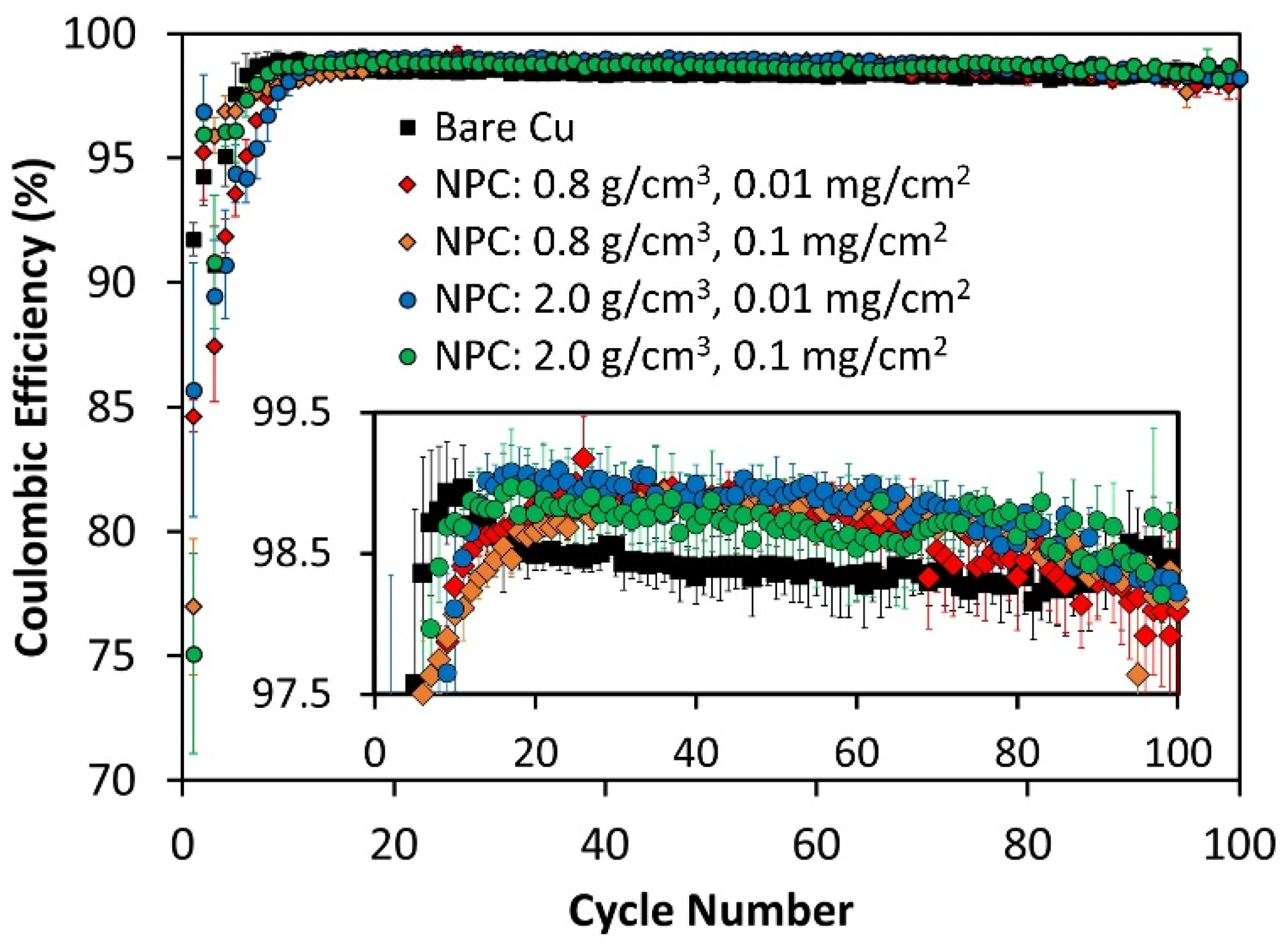
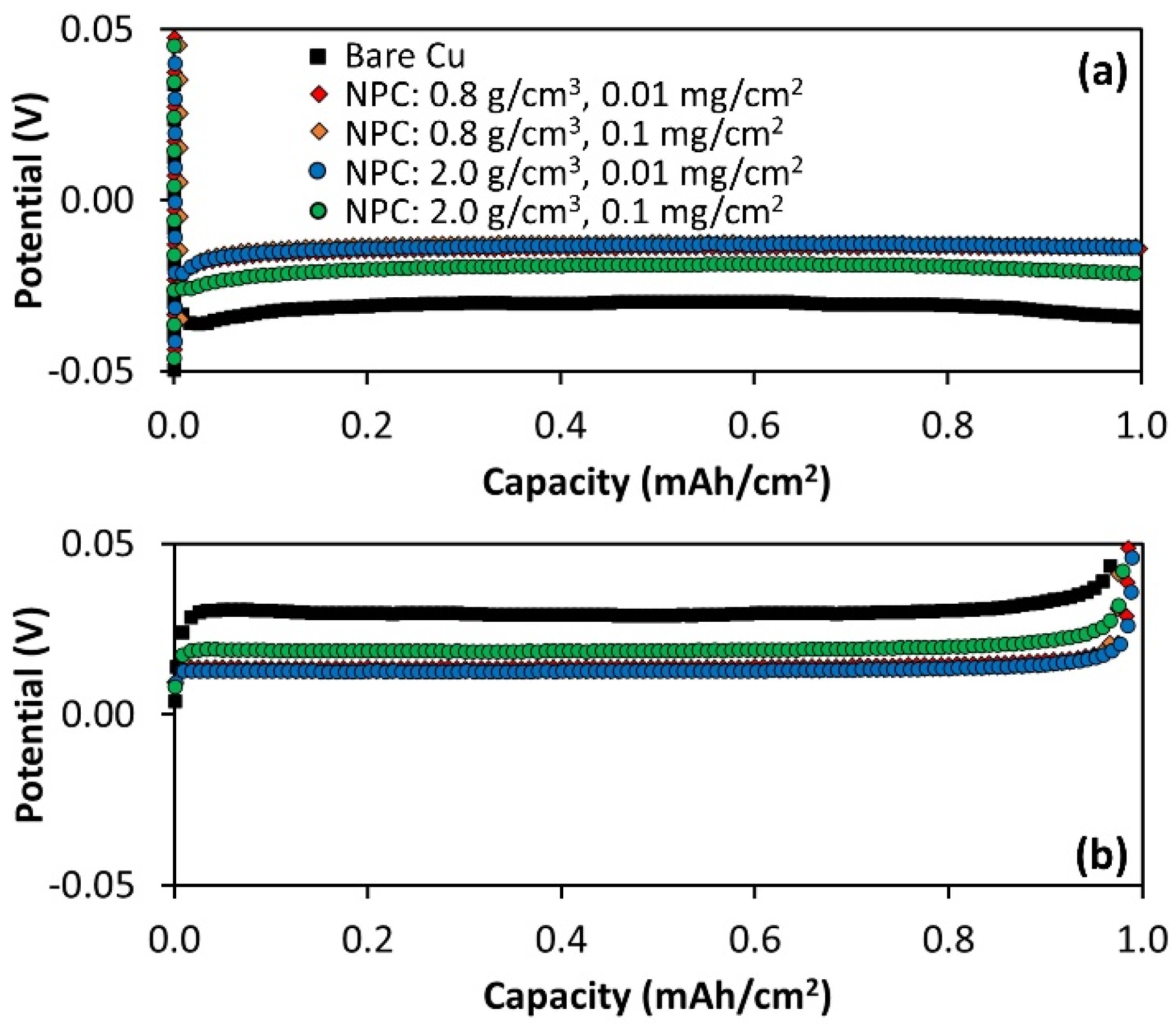
3.4. Li Metal Cycling and Calendar Aging on NPC-Coated Cu

SEM images in Figure 2 and Figure 3, as well as first-cycle Li electrodeposition/electrodissolution data in Figure 1, demonstrate that NPC density and thickness impact initial nucleation, growth, and CE of the first Li electrodeposition/electrodissolution cycle. Figure 4 shows CE as a function of cycle number for 100 Li electrodeposition/electrodissolution cycles on bare Cu and NPC-coated Cu with varied density and loading. As already shown in Table 2, the CE during the first cycle is lower for all NPC-coated samples than for Li cycling on bare Cu due to the irreversible lithiation of NPC within the voltage limits studied here. The CEs during the second Li electrodeposition/electrodissolution cycle on NPC-coated Cu are much higher than in cycle 1 because NPC is already lithiated such that additional losses associated with the irreversible NPC Li insertion are minimal.
For the first ~10 cycles, the CE is generally slightly higher for bare Cu than NPC-coated Cu, but then the CE drops for the bare Cu and rises for the NPC-coated Cu. The CE drop on bare Cu may be related to different Li morphological evolution than on NPC-coated Cu. The 2.0 g/cm3 NPC coatings generally enable slightly higher CE during initial Li cycling than the 0.8 g/cm3 NPC coatings, though these changes are largely within the error of the measurements. This trends with our prior work [61], which shows lower CE for Li+ insertion into 0.8 g/cm3 NPC than 2.0 g/cm3 and is attributed to higher surface area for SEI growth on lower density NPC. This could contribute to lower CE for Li electrodeposition as well, or the CE differences could arise from differences in Li electrodeposition morphology. The more nodular Li morphology for 2.0 g/cm3 NPC coatings is possibly less prone to dead Li or dendrite formation than the long strands prevalent for 0.8 g/cm3 NPC. All NPC samples exhibit higher Li cycling CE than the bare Cu samples after about 10 cycles. However, the CE on bare Cu stabilizes at around 20 cycles, and the CE on NPC-coated Cu samples begins dropping near 100 cycles. We chose to stop the cells at 100 cycles because the benefits of NPC coatings are diminishing by 100 cycles, such that NPC would likely not continue benefiting from cycling for longer cycle numbers. Due to the use of thin (50 μm Li on Cu) counter-electrodes in these cells, the decline in CE may be related to excess Li inventory depletion. The changes in morphology imparted by NPC coatings may decrease with cycling as the coatings break up and may no longer effectively guide morphological evolution, as has been suggested previously to occur with thin coatings [29] and as evidenced by NPC cracking in Figure 3.
To better understand the differences between Li cycling on bare versus NPC-coated Cu, Figure 5 shows Li electrodeposition and electrodissolution curves for cycle 50, where the CE for Li cycling is higher on all NPC-coated Cu samples than on bare Cu samples. Clearly, the overpotential is lower for the NPC-coated Cu samples relative to bare Cu, suggesting that NPC enables better kinetics, possibly via more favorable morphological control or by promoting a more compact, less resistive SEI. This trend of lower overpotential for NPC-coated versus bare Cu after 50 cycles is also demonstrated for Li cycled in the alternative electrolyte we tested (1 M LiTFSI in DOL/DME 1% LiNO3), as shown in Figure S11. Although the LiTFSI electrolyte generally exhibits worse cycling performance than the LiFSI electrolyte, the overpotential trends are consistent.
To further evaluate the impact of NPC coatings on Li metal anode cycling, we also performed calendar aging tests. We previously showed with a similar protocol that some coatings on Cu can improve the calendar aging performance of Li metal anodes, and some coatings can degrade calendar aging [29]. Specifically, we recently showed that LiF exacerbates calendar aging, while ZnO and Al2O3 improve calendar aging [29] due to differences in how these coatings guide Li morphological evolution. We commonly employ a calendar aging test consisting mostly of continuous cycling, but we intermittently add rest steps between electrodeposition and electrodissolution at regular intervals to evaluate the CE loss during rest [20,29,30,63]. We generally conclude that CE losses during intermittent rest steps largely result from dead Li formation during rest, which can then be recovered in subsequent cycles [29,30,63]. Other groups have also concluded CE losses partially result from dead Li formation during calendar aging and that this dead Li can be recovered through strategic electrochemical protocols [65]. Much of the lost CE is recovered on subsequent cycles because dead Li can reconnect after being stranded during rest steps. Since the observed calendar aging is thought to be largely related to the propensity to form dead Li, coatings that impact Li morphology evolution may also impact calendar aging. Because NPC coatings significantly affect Li morphology, as demonstrated in Figure 2 and Figure 3, we hypothesized that the NPC coatings may also affect calendar aging.
We tested calendar aging using a protocol similar to several previous studies [20,29,30,63], where we cycled continuously for five cycles and then rested 24 h between Li electrodeposition and electrodissolution after every group of five cycles. This protocol is shown in Figure 6a. Figure 6b shows calendar aging results for Li electrodeposition on NPC-coated and bare Cu current collectors, and Figure S12 shows the data with a larger range of CE and cycle numbers as well as with error bars. The CE drops every 5th cycle when 24 h rest steps are imposed between Li electrodeposition and electrodissolution (cycles 6, 11, 16, 21, etc.). The CE then recovers on the subsequent cycles, consistent with prior observations [20,29,30,63]. Curiously, while the 2.0 g/cm3 NPC coatings tend to enable the highest Li cycling CE during continuous cycling, the 0.8 g/cm3 NPC coatings tend to enable the highest Li cycling CE during these calendar aging tests, with this trend reversed only in very early cycles. All cells exhibit fairly similar magnitudes of CE drops during the rest steps, though, indicating that calendar aging is not significantly improved or exacerbated by the use of NPC coatings, perhaps suggesting that the morphological control afforded by NPC coatings does not significantly change the propensity for dead Li formation during rest.
It is unlikely that the NPC coatings behave like ASEIs and protect the Li from the electrolyte by blocking electron transport to the electrolyte since NPC is expected to be reasonably conductive. Furthermore, NPC is unlikely to act as a conformal ASEI because Li tends to deposit on top of NPC for 0.8 g/cm3 and 0.01 g/cm2 coated Cu or break up the NPC for 2.0 g/cm3 NPC-coated Cu. However, it is worth noting that the electrodeposition–electrodissolution curves for cycle 50 in Figure 6c–d again show that Li cycling on NPC-coated Cu exhibits lower overpotential than Li cycled on bare Cu. The smooth curves and absence of stochastic variations or CE above 100% suggest that this lower overpotential is unlikely due to something artificial like soft shorts. Compared to overpotential differences between bare and NPC-coated Cu samples on cycle 50 after continuous cycling with no rest steps shown in Figure 5, the overpotential differences are much more significant for the samples in Figure 6c–d that experience intermittent rest steps (note the change in scale in Figure 5 and Figure 6), perhaps suggesting that SEI growth during intermittent rest steps leads to impedance rise and that Li cycled on NPC-coated Cu reduces this SEI growth, either through chemical interactions or changes in Li morphology.

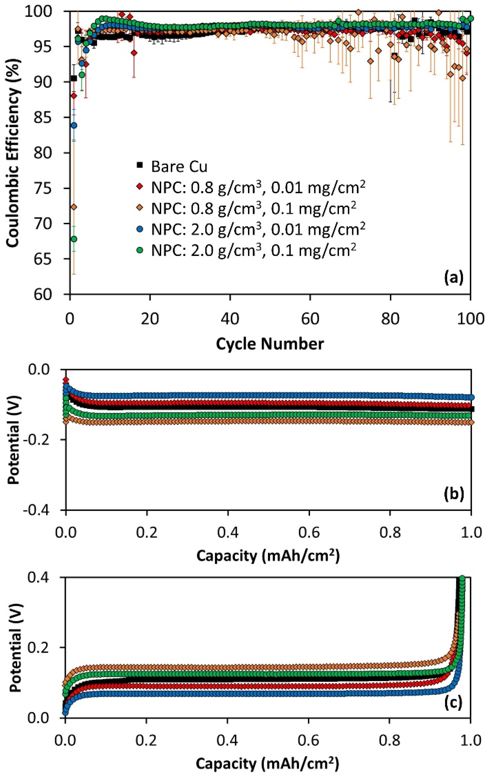
3.5. Higher Current Li Cycling on Bare and NPC-Coated Cu

The reduced overpotential caused by cycling Li on NPC-coated Cu relative to bare Cu suggests that performance improvements with NPC-coated Cu might be more significant at higher current density. Figure 7a shows Li cycling at a significantly higher rate of 2 mA/cm2 (compared to 0.5 mA/cm2 used in other tests) on NPC-coated and bare Cu current collectors. Higher current density cycling leads to more stochastic behavior, lower CE, and larger variation from cell to cell (and thus larger error bars) than low current cycling. This is expected, as it is more challenging to cycle Li at high current densities, and Li cycling is a stochastic process in the best case. Regardless, Li cycling on NPC-coated Cu current collectors exhibits higher CE in general than Li cycling on bare Cu (see zoomed plot in Figure S13 for better clarity) for the first 50 cycles. After about 50 cycles, the error bars increase due to increased stochasticity, and NPC does not provide significant benefit over cycling on bare Cu. We chose to stop cycling cells at 100 cycles because the NPC coating benefits diminish well before this cycling limit. Because 2 mA/cm2 already is a very aggressive rate, leading to poor performance, higher rate testing was not pursued.
As is also observed in Figure 4, the higher-density NPC coatings tend to improve Li cycling CE slightly more than lower-density NPC coatings during continuous cycling tests. All NPC-coated Cu samples exhibit capacity associated with NPC lithiation when cycled at high current density, as they did at low current density. Figure S14 shows that the first Li+ insertion capacity is larger with the higher mass loading NPC coatings, as expected and consistent with Figure 1. The dip and plateau associated with the first NPC lithiation for 2.0 g/cm3, 0.1 mg/cm2 NPC in Figure S14 is pushed to lower potentials at a higher current density than it was in Figure 1. Again, this dip likely occurs for 2.0 g/cm3, 0.1 mg/cm2 NPC because the thick, dense NPC coating experiences slow Li+ transport through the thickness of the coating.
All cells exhibited higher Li plateau overpotentials at high currents than at low currents. It is not surprising that the overpotential increases at higher current density because transport must occur more quickly to keep up with the increased current. However, while the Li cycling overpotentials on NPC-coated Cu when cycled at 0.5 mA/cm2 are consistently lower compared to bare Cu for all NPC conditions, the overpotential trends for Li cycling on NPC-coated Cu relative to bare Cu are loading-dependent when cycled at 2.0 mA/cm2. This is demonstrated in Figure 7b–c for cycle 50 with high current cycling, which shows that cells with thinner NPC coatings exhibit lower overpotential than bare Cu, but cells with thicker NPC coatings exhibit higher overpotential than bare Cu. This suggests that ionic transport through the thickness of the NPC coatings does not limit kinetics at 0.5 mA/cm2, but ionic transport through the NPC coatings does limit kinetics at 2.0 mA/cm2. These results imply that both the density and thickness of carbon coatings on Cu play roles in Li cycling performance and morphology.

4. Discussion

Many coatings have been used to impact Li cycling or nucleation and growth, such as LiF, ZnO, Al2O3, carbons, and polymers [20,21,22,23,24,25,26,27,28,29,30,31,32,33,34,35,36,37], with varying impacts. Some coatings show significant Li cycling benefits [21,22,23,28,31]. However, because the electrochemical conditions, coating thicknesses, and cell designs differ significantly between different studies, it is difficult to compare studies to determine the most effective coatings. Carbon coatings are particularly variable because their properties differ with the synthesis method, and they can be tuned and functionalized to enable changes in properties that can impact Li cycling. Therefore, in this study, we focus on systematically varying thickness and density to understand the impact of these tuning parameters.
NPC films with varied mass density and mass loading were coated onto Cu and evaluated as lithiophilic current collectors for Li metal anode cycling. Previous studies investigating carbon coatings for Li cycling can be divided into two types of strategies: thin ASEIs [20,21,22,23,24,25,26,27,28,29,30,31,32,33,34,35,36,37] and 3D scaffolds [38,39,40,41,42,43,44,45,46,47,48,49,50,51,52,53]. The former can guide nucleation and/or protect the Li similarly to an innate SEI and contributes minimally to inactive mass and volume, but ASEIs can break up over time and cannot constrain Li volume expansion by incorporating Li into pores. The latter can lower local current density by acting as a 3D current collector to constrain Li volume expansion in its pores but can add significant mass and volume that may negate the benefits of adopting Li metal anodes. Herein, the mass and volume of the NPC were carefully considered to ensure that the mass and volume of the coatings did not significantly decrease gravimetric and volumetric capacity relative to Li metal cycled on pristine Cu (Table 1), consistent with the ASEI strategy.
A summary of performance metrics comparing Li cycling on bare Cu and Cu with varied thickness and density NPC coatings is shown in Table 3. NPC coatings generally lead to modestly higher CE than on bare Cu during Li cycling and calendar aging tests, except initial cycling (Figure 4, Figure 6, and Figure 7 and Table 2). Lower-density NPC coatings on Cu enable the highest CE during calendar aging tests, and higher-density NPC coatings on Cu enable the highest CE during cycling tests (at low and high current density). Cycle and calendar life CE improvements afforded with NPC-coated Cu relative to bare Cu often decline by 100 cycles, showing that these thin NPC films are insufficient to provide drastic long-term benefits to Li cycling performance, possibly because the coatings break up over time. Three-dimensional scaffolds may be more effective at affecting long-term cycling, but they also add significantly more mass and volume, which impacts practical energy density.
Coatings like NPC can impact Li cycling by guiding nucleation and growth or by acting as protective “ASEIs” that block electron transfer and allow ion transfer, protecting the Li from reactivity with the electrolyte. It is unlikely that NPC coatings function as true ASEIs because NPC is not an insulator. It is more likely that NPC coatings affect Li electrodeposition/electrodissolution performance by guiding nucleation and growth due to their lithiophilic nature. NPC lithiophilicity was hypothesized due to its ability to undergo Li+ insertion before the Li electrodeposition reaction (Figure 1). Cells with NPC-coated Cu generally exhibit lower overpotentials for Li electrodeposition relative to those with bare Cu (Figure 5 and Figure 6) when cycling at 0.5 mA/cm2.
Despite this lower overpotential, surprisingly, NPC-coated Cu samples generally exhibit lower Li nucleation density than bare Cu. NPC coatings tend to promote larger, more distributed Li deposits with extensive growth from a few sites compared to Li growth on bare Cu (Figure 2). Nucleation is more significantly hindered by thick NPC coatings (particularly for dense NPC); this is evidenced by the nucleation overpotential for cells with thick, dense NPC-coated Cu in Figure 1 when cycling Li at 0.5 mA/cm2 and by the higher overpotentials observed for cells with thick NPC-coated Cu when cycling Li at 2 mA/cm2 in Figure 7 relative to bare Cu or Cu with thin NPC coatings. Li+ diffusion limitations through NPC coatings may cause Li to preferentially plate on existing nucleation sites where Li has already grown through the NPC rather than Li+ diffusing through the NPC to begin new nucleation sites, and this diffusion limitation would be expected to be more significant in thicker films, manifesting in larger deposits for thicker NPC films (Figure 2) and more significant overpotential during higher current cycling (Figure 7). Lower NPC density promotes the formation of long strands of Li metal deposits anchored at a few locations rather than a homogenous film or many Li deposits anchored at a larger number of nucleation sites. Higher-density NPC promotes more nodular Li growth, with a mixture of nodules and strands for thinner NPC coatings. Thicker NPC coatings promote larger deposits relative to thin NPC coatings for both densities, likely resulting from sparser nucleation leading to more prevalent growth from fewer nucleation sites.
The impact of NPC thickness and density on Li morphology was also investigated by cross-sectional cryogenic FIB and SEM (Figure 3) to understand whether Li deposits beneath or on top of the NPC film. Thin, low-density NPC promotes Li nucleation and growth on top of the NPC coating. Thick, low-density NPC coatings and thick or thin, high-density NPC coatings promote Li nucleation below the NPC. High-density NPC coatings promote growth through cracks in the NPC film, which are clearly observed by the NPC wrapping around Li deposits at sites where they are anchored to the Cu. The differences in Li morphology resulting from NPC coatings relative to bare Cu were similar even when the electrolyte was modified, suggesting that coatings on Cu play a significant role in guiding nucleation and growth.

5. Conclusions

NPC films with varied mass density and mass loading were coated onto Cu and evaluated as lithiophilic current collectors for Li metal anode cycling. The mass and volume of the NPC were carefully considered to ensure that the mass and volume of the coatings did not significantly decrease gravimetric and volumetric capacity relative to Li metal cycled on the pristine Cu. NPC coatings modestly improve Li cycling relative to bare Cu, with high-density NPC coatings showing the largest improvements. In contrast, low-density NPC coatings show the largest improvements in calendar aging behavior.
During both cycling and calendar aging testing, Li generally plates with lower overpotential on NPC-coated Cu than on bare Cu. Despite this lower overpotential and the lithiophilic nature of NPC, NPC does not improve nucleation density or Li deposit morphology. The Li morphological evolution on NPC-coated Cu varies significantly from bare Cu and morphology varies with NPC density and thickness. Low-density, thin NPC coatings promote long strands of Li with low nucleation density that deposit on top of the NPC. Low-density, thick NPC coatings promote electrodeposition at the NPC-Cu interface instead, indicating potential electronic conductivity limitations in the NPC films after lithiation and SEI formation. High-density, thin, and thick NPC similarly guide Li electrodeposition to occur at the Cu-NPC interface, but high-density NPC shows more propensity to crack and bend around the Li deposits relative to low density, thick NPC. This work highlights the importance of considering the density, thickness, and mass of carbon coatings when designing coatings for Li cycling and shows that these parameters significantly impact Li nucleation and growth behavior.

Supplementary Materials

The following supporting information can be downloaded at: https://www.mdpi.com/article/10.3390/batteries11010010/s1, Figure S1: (a) Annotated picture of PLD process for NPC deposition and (b) Ar pressure versus mass density calibration curve for PLD NPC deposition; Figure S2: SEM images showing representative (a) 0.8 g/cm3, 0.1 mg/cm2 (1250 nm thick) and (b) 2.0 g/cm3, 0.1 mg/cm2 (500 nm thick) NPC films deposited with PLD; Figure S3: Potential versus capacity for the first Li deposition on bare Cu and NPC-coated Cu current collectors in coin cells versus Li metal in 1 M LiFSI in DOL/DME 1% LiNO3 electrolyte with (a) full potential range shown and (b) zoomed region to show detail in the NPC Li insertion range. Li is deposited at 0.5 mA/cm2 to 1 mAh/cm2. This figure corresponds to Figure 1; Figure S4: Potential versus capacity for the first Li (a-b) deposition and (c) stripping half cycle on bare Cu and NPC-coated Cu current collectors in coin cells versus Li metal in 1 M LiFSI in DOL/DME 1% LiNO3 electrolyte. Li is deposited and stripped at 0.5 mA/cm2 to 1 mAh/cm2. Variations observed in the initial part of the Li deposition curves for 2.0 g/cm3 and 0.1 mg/cm2 NPC samples are highlighted in (b). This figure corresponds to Figure 1; Figure S5: Potential versus capacity for the second Li deposition on bare Cu and NPC-coated Cu current collectors in coin cells versus Li metal in 1 M LiFSI in DOL/DME 1% LiNO3 electrolyte with (a) the full potential range shown for completeness and (b) a zoomed region to show detail in the NPC Li+ insertion range. Li is deposited at 0.5 mA/cm2 to 1 mAh/cm2. This figure corresponds to Figure 1; Figure S6: Room temperature SEM images of electrodes after the first Li deposition on bare Cu and NPC-coated Cu current collectors in coin cells versus Li metal in 1 M LiFSI in DOL/DME 1% LiNO3 electrolyte. Densities and mass loadings of NPC are given above the images, and these correspond to the electrochemical results shown in Figure 1 and are at lower magnification than the images in Figure 2. Li is deposited at 0.5 mA/cm2 to 1 mAh/cm2; Figure S7: Room temperature SEM images of electrodes after the first Li deposition on bare Cu and NPC-coated Cu current collectors in coin cells versus Li metal in an alternative electrolyte (1 M LiTFSI in DOL/DME 1% LiNO3) relative to Figure 1 and Figure 2. Li is deposited at 0.5 mA/cm2 to 1 mAh/cm2; Figure S8: Room temperature photographs of electrodes after the first Li stripping on bare Cu and NPC-coated Cu current collectors in coin cells versus Li metal in 1 M LiFSI in DOL/DME 1% LiNO3 electrolyte. These correspond to the electrochemical results shown in Figure 1. Li is deposited and stripped at 0.5 mA/cm2 to 1 mAh/cm2. Note that the sample shown here after Li deposition on 2.0 g/cm3, 0.1 mg/cm2 NPC is pictured on the cell spacer (and in different lighting conditions) because it stuck to the spacer after cell disassembly, and removal proved difficult without damaging the sample; Figure S9: Cryogenic SEM image after cryogenic FIB cross-section and corresponding EDS maps of Li after the first deposition on a bare Cu current collector in a coin cell versus Li metal in 1 M LiFSI in DOL/DME 1% LiNO3 electrolyte. Li is deposited at 0.5 mA/cm2 to 1 mAh/cm2. The cross-section (top left) highlights the Li grains, and the chemical distribution is shown in corresponding EDS maps for C, O, and F (top right and bottom row); Figure S10: Photographs (top) and SEM images (bottom) of electrodes after one Li deposition on 2.0 g/cm3, 0.1 mg/cm2 NPC-coated Cu samples after one Li electrodeposition (left) and one stripping (right) step in alternative electrolyte 1 M LiTFSI in DOL/DME with 1% LiNO3. These show significant flaking of the NPC coating compared to other conditions and compared to samples with the LiFSI electrolyte used in most of this study; Figure S11: Potential versus capacity for the 50th cycle of Li (top) deposition and (bottom) stripping on bare Cu and NPC-coated Cu current collectors in coin cells versus Li metal cycled with alternative electrolyte 1 M LiTFSI in DOL/DME 1% LiNO3. Li is deposited at 0.5 mA/cm2 to 1 mAh/cm2; Figure S12: Calendar aging data for Li deposition and stripping on bare Cu and NPC-coated Cu current collectors in coin cells versus Li metal in 1 M LiFSI in DOL/DME 1% LiNO3 electrolyte. Li is deposited at 0.5 mA/cm2 to 1 mAh/cm2. Current density is applied such that the cells undergo continuous cycling except for a 24 h rest every 5th cycle (i.e., cycles 6, 11, 16,…). Both figures show CE versus cycle number for the first 50 cycles, including continuous cycling and rest cycles, but the top plot shows a wider CE scale, and the bottom plot includes error bars with a narrower CE scale to show where error bars do and do not overlap; Figure S13: CE versus cycle number Li deposition and stripping on bare Cu and NPC-coated Cu current collectors in coin cells versus Li metal in 1 M LiFSI in DOL/DME 1% LiNO3 electrolyte. Li is deposited at 2 mA/cm2 to 1 mAh/cm2. This is a zoomed version of Figure 7 to show detail. The error bars are large on the orange data set, mostly due to one replicate performing poorer than the others; Figure S14: Potential versus capacity for the first Li deposition on bare Cu and NPC-coated Cu current collectors in coin cells versus Li metal in 1 M LiFSI in DOL/DME 1% LiNO3 electrolyte. Li is deposited at 2 mA/cm2 to 1 mAh/cm2.

Author Contributions

Conceptualization, K.L.H., S.G. and M.P.S.; methodology, M.A.W., S.G., K.L.H., D.M.L. and M.P.S.; validation, K.L.H. and M.P.S.; formal analysis, K.L.H., D.M.L., S.G., R.I.M. and L.C.M.; investigation, B.W., R.I.M., S.G., D.M.L., M.A.W. and L.C.M.; data curation, A.S., B.W., L.C.M., D.M.L., K.L.H., R.I.M. and S.G.; writing—original draft preparation, K.L.H.; writing—review and editing, K.L.H., S.G., D.M.L., R.I.M., M.A.W., L.C.M., A.S., B.W. and M.P.S.; supervision, K.L.H. and M.P.S.; project administration, K.L.H. and M.P.S.; funding acquisition, K.L.H. and M.P.S. All authors have read and agreed to the published version of the manuscript.

Funding

This work was supported by the Laboratory Directed Research and Development program at Sandia National Laboratories and the New Mexico Small Business Program. This work was performed, in part, at the Center for Integrated Nanotechnologies, an Office of Science User Facility operated by the U.S. Department of Energy (DOE) Office of Science. Sandia National Laboratories is a multimission laboratory managed and operated by National Technology and Engineering Solutions of Sandia, LLC., a wholly owned subsidiary of Honeywell International, Inc., for the U.S. Department of Energy’s National Nuclear Security Administration under contract DE-NA-0003525. This work was authored in part by the National Renewable Energy Laboratory, operated by Alliance for Sustainable Energy, LLC, for the U.S. Department of Energy (DOE) under Contract No. DE-AC36-08GO28308.

Data Availability Statement

The raw data supporting the conclusions of this article will be made available by the authors upon request.

Acknowledgments

We thank Lindsay Quarrie at Space Sciences Corporation for useful discussions.

Conflicts of Interest

Author Subrahmanyam Goriparti is employed by the company General Motors. Author Daniel M. Long is employed by the company NBACC. Author Matthaeus A. Wolak is employed by the company Northrop Grumman. Author Alexander Sananes is employed by the company Physical Sciences Inc. The remaining authors declare that the research was conducted in the absence of any commercial or financial relationships that could be construed as a potential conflict of interest.

References

  1. Adams, B.D.; Zheng, J.; Ren, X.; Xu, W.; Zhang, J.G. Accurate determination of Coulombic efficiency for lithium metal anodes and lithium metal batteries. Adv. Energy Mater. 2018, 8, 1702097. [Google Scholar] [CrossRef]
  2. Li, L.; Basu, S.; Wang, Y.; Chen, Z.; Hundekar, P.; Wang, B.; Shi, J.; Shi, Y.; Narayanan, S.; Koratkar, N. Self-heating–induced healing of lithium dendrites. Science 2018, 359, 1513–1516. [Google Scholar] [CrossRef]
  3. Ding, F.; Xu, W.; Chen, X.; Zhang, J.; Shao, Y.; Engelhard, M.H.; Zhang, Y.; Blake, T.A.; Graff, G.L.; Liu, X. Effects of cesium cations in lithium deposition via self-healing electrostatic shield mechanism. J. Phys. Chem. C 2014, 118, 4043–4049. [Google Scholar] [CrossRef]
  4. Choi, J.-W.; Cheruvally, G.; Kim, D.-S.; Ahn, J.-H.; Kim, K.-W.; Ahn, H.-J. Rechargeable lithium/sulfur battery with liquid electrolytes containing toluene as additive. J. Power Sources 2008, 183, 441–445. [Google Scholar] [CrossRef]
  5. Jozwiuk, A.; Berkes, B.B.; Weiß, T.; Sommer, H.; Janek, J.; Brezesinski, T. The critical role of lithium nitrate in the gas evolution of lithium–sulfur batteries. Energy Environ. Sci. 2016, 9, 2603–2608. [Google Scholar] [CrossRef]
  6. Zhang, S.S. A review on electrolyte additives for lithium-ion batteries. J. Power Sources 2006, 162, 1379–1394. [Google Scholar] [CrossRef]
  7. Han, H.-B.; Zhou, S.-S.; Zhang, D.-J.; Feng, S.-W.; Li, L.-F.; Liu, K.; Feng, W.-F.; Nie, J.; Li, H.; Huang, X.-J. Lithium bis (fluorosulfonyl) imide (LiFSI) as conducting salt for nonaqueous liquid electrolytes for lithium-ion batteries: Physicochemical and electrochemical properties. J. Power Sources 2011, 196, 3623–3632. [Google Scholar] [CrossRef]
  8. Ding, F.; Xu, W.; Chen, X.; Zhang, J.; Engelhard, M.H.; Zhang, Y.; Johnson, B.R.; Crum, J.V.; Blake, T.A.; Liu, X. Effects of carbonate solvents and lithium salts on morphology and coulombic efficiency of lithium electrode. J. Electrochem. Soc. 2013, 160, A1894–A1901. [Google Scholar] [CrossRef]
  9. Naoi, K.; Mori, M.; Naruoka, Y.; Lamanna, W.M.; Atanasoski, R. The Surface Film Formed on a Lithium Metal Electrode in a New Imide Electrolyte, Lithium Bis (perfluoroethylsulfonylimide) [LiN(C2F5SO2)2]. J. Electrochem. Soc. 1999, 146, 462–469. [Google Scholar] [CrossRef]
  10. Qian, J.; Henderson, W.A.; Xu, W.; Bhattacharya, P.; Engelhard, M.; Borodin, O.; Zhang, J.-G. High rate and stable cycling of lithium metal anode. Nat. Commun. 2015, 6, 6362. [Google Scholar] [CrossRef]
  11. Takada, K. Progress and prospective of solid-state lithium batteries. Acta Mater. 2013, 61, 759–770. [Google Scholar] [CrossRef]
  12. Sun, C.; Liu, J.; Gong, Y.; Wilkinson, D.P.; Zhang, J. Recent advances in all-solid-state rechargeable lithium batteries. Nano Energy 2017, 33, 363–386. [Google Scholar] [CrossRef]
  13. Thangadurai, V.; Narayanan, S.; Pinzaru, D. Garnet-type solid-state fast Li ion conductors for Li batteries: Critical review. Chem. Soc. Rev. 2014, 43, 4714–4727. [Google Scholar] [CrossRef]
  14. Hallinan, D.T., Jr.; Balsara, N.P. Polymer electrolytes. Annu. Rev. Mater. Res. 2013, 43, 503–525. [Google Scholar] [CrossRef]
  15. Bachman, J.C.; Muy, S.; Grimaud, A.; Chang, H.-H.; Pour, N.; Lux, S.F.; Paschos, O.; Maglia, F.; Lupart, S.; Lamp, P. Inorganic solid-state electrolytes for lithium batteries: Mechanisms and properties governing ion conduction. Chem. Rev. 2015, 116, 140–162. [Google Scholar] [CrossRef]
  16. Liu, Y.; Liu, Q.; Xin, L.; Liu, Y.; Yang, F.; Stach, E.A.; Xie, J. Making Li-metal electrodes rechargeable by controlling the dendrite growth direction. Nature Energy 2017, 2, 17083. [Google Scholar] [CrossRef]
  17. Ma, L.; Fu, C.; Li, L.; Mayilvahanan, K.S.; Watkins, T.; Perdue, B.R.; Zavadil, K.R.; Helms, B.A. Nanoporous Polymer Films with High Cation Transference Number Stabilize Lithium Metal Anodes in Light-Weight Batteries for Electrified Transportation. Nano Lett. 2019, 19, 1387–1394. [Google Scholar] [CrossRef]
  18. Mikhaylik, Y.V.; Kovalev, I.; Schock, R.; Kumaresan, K.; Xu, J.; Affinito, J. High energy rechargeable Li-S cells for EV application: Status, remaining problems and solutions. Ecs Trans. 2010, 25, 23–34. [Google Scholar] [CrossRef]
  19. Wilkinson, D.P.; Blom, H.; Brandt, K.; Wainwright, D. Effects of physical constraints on Li cyclability. J. Power Sources 1991, 36, 517–527. [Google Scholar] [CrossRef]
  20. Harrison, K.L.; Zavadil, K.R.; Hahn, N.T.; Meng, X.; Elam, J.W.; Leenheer, A.; Zhang, J.-G.; Jungjohann, K.L. Lithium self-discharge and its prevention: Direct visualization through in situ electrochemical scanning transmission electron microscopy. ACS Nano 2017, 11, 11194–11205. [Google Scholar] [CrossRef]
  21. Cao, Y.; Meng, X.; Elam, J.W. Atomic Layer Deposition of LixAlyS Solid-State Electrolytes for Stabilizing Lithium-Metal Anodes. ChemElectroChem 2016, 3, 858–863. [Google Scholar] [CrossRef]
  22. Kozen, A.C.; Lin, C.-F.; Pearse, A.J.; Schroeder, M.A.; Han, X.; Hu, L.; Lee, S.-B.; Rubloff, G.W.; Noked, M. Next-generation lithium metal anode engineering via atomic layer deposition. ACS Nano 2015, 9, 5884–5892. [Google Scholar] [CrossRef] [PubMed]
  23. Kazyak, E.; Wood, K.N.; Dasgupta, N.P. Improved cycle life and stability of lithium metal anodes through ultrathin atomic layer deposition surface treatments. Chem. Mater. 2015, 27, 6457–6462. [Google Scholar] [CrossRef]
  24. Aetukuri, N.B.; Kitajima, S.; Jung, E.; Thompson, L.E.; Virwani, K.; Reich, M.L.; Kunze, M.; Schneider, M.; Schmidbauer, W.; Wilcke, W.W. Flexible Ion-Conducting Composite Membranes for Lithium Batteries. Adv. Energy Mater. 2015, 5, 1500265. [Google Scholar] [CrossRef]
  25. Hao, X.; Zhu, J.; Jiang, X.; Wu, H.; Qiao, J.; Sun, W.; Wang, Z.; Sun, K. Ultrastrong Polyoxyzole Nanofiber Membranes for Dendrite-Proof and Heat-Resistant Battery Separators. Nano Lett. 2016, 16, 2981–2987. [Google Scholar] [CrossRef]
  26. Kang, I.S.; Lee, Y.-S.; Kim, D.-W. Improved cycling stability of lithium electrodes in rechargeable lithium batteries. J. Electrochem. Soc. 2014, 161, A53–A57. [Google Scholar] [CrossRef]
  27. Li, F.S.; Wu, Y.S.; Chou, J.; Winter, M.; Wu, N.L. A mechanically robust and highly ion-conductive polymer-blend coating for high-power and long-life lithium-ion battery anodes. Adv. Mater. 2015, 27, 130–137. [Google Scholar] [CrossRef]
  28. Yan, K.; Lee, H.-W.; Gao, T.; Zheng, G.; Yao, H.; Wang, H.; Lu, Z.; Zhou, Y.; Liang, Z.; Liu, Z. Ultrathin two-dimensional atomic crystals as stable interfacial layer for improvement of lithium metal anode. Nano Lett. 2014, 14, 6016–6022. [Google Scholar] [CrossRef]
  29. Merrill, L.C.; Long, D.M.; Small, K.A.; Jungjohann, K.L.; Leung, K.; Bassett, K.L.; Harrison, K.L. Role of coatings as artificial solid electrolyte interphases on lithium metal self-discharge. J. Phys. Chem. C 2022, 126, 17490–17501. [Google Scholar] [CrossRef]
  30. Bassett, K.L.; Small, K.A.; Long, D.M.; Merrill, L.C.; Warren, B.; Harrison, K.L. Interfacial pressure improves calendar aging of lithium metal anodes. Front. Batter. Electrochem. 2023, 2, 1292639. [Google Scholar] [CrossRef]
  31. Zheng, G.; Lee, S.W.; Liang, Z.; Lee, H.-W.; Yan, K.; Yao, H.; Wang, H.; Li, W.; Chu, S.; Cui, Y. Interconnected hollow carbon nanospheres for stable lithium metal anodes. Nat. Nanotechnol. 2014, 9, 618–623. [Google Scholar] [CrossRef] [PubMed]
  32. Arie, A.A.; Lee, J.K. Electrochemical characteristics of lithium metal anodes with diamond like carbon film coating layer. Diam. Relat. Mater. 2011, 20, 403–408. [Google Scholar] [CrossRef]
  33. Zhang, Y.; Liu, X.; Bai, W.; Tang, H.; Shi, S.; Wang, X.; Gu, C.; Tu, J. Magnetron sputtering amorphous carbon coatings on metallic lithium: Towards promising anodes for lithium secondary batteries. J. Power Sources 2014, 266, 43–50. [Google Scholar] [CrossRef]
  34. Liu, W.; Xia, Y.; Wang, W.; Wang, Y.; Jin, J.; Chen, Y.; Paek, E.; Mitlin, D. Pristine or highly defective? Understanding the role of graphene structure for stable lithium metal plating. Adv. Energy Mater. 2019, 9, 1802918. [Google Scholar] [CrossRef]
  35. Huang, S.; Tang, L.; Najafabadi, H.S.; Chen, S.; Ren, Z. A highly flexible semi-tubular carbon film for stable lithium metal anodes in high-performance batteries. Nano Energy 2017, 38, 504–509. [Google Scholar] [CrossRef]
  36. Bai, M.; Xie, K.; Yuan, K.; Zhang, K.; Li, N.; Shen, C.; Lai, Y.; Vajtai, R.; Ajayan, P.; Wei, B. A scalable approach to dendrite-free lithium anodes via spontaneous reduction of spray-coated graphene oxide layers. Adv. Mater. 2018, 30, 1801213. [Google Scholar] [CrossRef]
  37. Chen, Y.-T.; Abbas, S.A.; Kaisar, N.; Wu, S.H.; Chen, H.-A.; Boopathi, K.M.; Singh, M.; Fang, J.; Pao, C.-W.; Chu, C.-W. Mitigating Metal Dendrite Formation in Lithium–Sulfur Batteries via Morphology-Tunable Graphene Oxide Interfaces. ACS Appl. Mater. Interfaces 2018, 11, 2060–2070. [Google Scholar] [CrossRef]
  38. Hong, B.; Fan, H.; Cheng, X.-B.; Yan, X.; Hong, S.; Dong, Q.; Gao, C.; Zhang, Z.; Lai, Y.; Zhang, Q. Spatially uniform deposition of lithium metal in 3D Janus hosts. Energy Storage Mater. 2019, 16, 259–266. [Google Scholar] [CrossRef]
  39. Yun, Q.; He, Y.B.; Lv, W.; Zhao, Y.; Li, B.; Kang, F.; Yang, Q.H. Chemical dealloying derived 3D porous current collector for Li metal anodes. Adv. Mater. 2016, 28, 6932–6939. [Google Scholar] [CrossRef]
  40. Wang, L.; Zhu, X.; Guan, Y.; Zhang, J.; Ai, F.; Zhang, W.; Xiang, Y.; Vijayan, S.; Li, G.; Huang, Y. ZnO/carbon framework derived from metal-organic frameworks as a stable host for lithium metal anodes. Energy Storage Mater. 2018, 11, 191–196. [Google Scholar] [CrossRef]
  41. Ye, H.; Xin, S.; Yin, Y.-X.; Li, J.-Y.; Guo, Y.-G.; Wan, L.-J. Stable Li plating/stripping electrochemistry realized by a hybrid Li reservoir in spherical carbon granules with 3D conducting skeletons. J. Am. Chem. Soc. 2017, 139, 5916–5922. [Google Scholar] [CrossRef] [PubMed]
  42. Zhao, C.; Yu, C.; Li, S.; Guo, W.; Zhao, Y.; Dong, Q.; Lin, X.; Song, Z.; Tan, X.; Wang, C. Ultrahigh-Capacity and Long-Life Lithium–Metal Batteries Enabled by Engineering Carbon Nanofiber–Stabilized Graphene Aerogel Film Host. Small 2018, 14, 1803310. [Google Scholar] [CrossRef] [PubMed]
  43. Zhu, Z.-W.; Wang, Z.-Y.; Liu, S.; Li, G.-R.; Gao, X.-P. Uniform lithium plating within 3D Cu foam enabled by Ag nanoparticles. Electrochim. Acta 2021, 379, 138152. [Google Scholar] [CrossRef]
  44. Sun, Z.; Jin, S.; Jin, H.; Du, Z.; Zhu, Y.; Cao, A.; Ji, H.; Wan, L.J. Robust Expandable Carbon Nanotube Scaffold for Ultrahigh-Capacity Lithium-Metal Anodes. Adv. Mater. 2018, 30, 1800884. [Google Scholar] [CrossRef]
  45. Yu, Y.; Huang, W.; Song, X.; Wang, W.; Hou, Z.; Zhao, X.; Deng, K.; Ju, H.; Sun, Y.; Zhao, Y. Thermally reduced graphene paper with fast Li ion diffusion for stable Li metal anode. Electrochim. Acta 2019, 294, 413–422. [Google Scholar] [CrossRef]
  46. Huang, G.; Han, J.; Zhang, F.; Wang, Z.; Kashani, H.; Watanabe, K.; Chen, M. Lithiophilic 3D Nanoporous Nitrogen-Doped Graphene for Dendrite-Free and Ultrahigh-Rate Lithium-Metal Anodes. Adv. Mater. 2019, 31, 1805334. [Google Scholar] [CrossRef]
  47. Lin, D.; Liu, Y.; Liang, Z.; Lee, H.-W.; Sun, J.; Wang, H.; Yan, K.; Xie, J.; Cui, Y. Layered reduced graphene oxide with nanoscale interlayer gaps as a stable host for lithium metal anodes. Nat. Nanotechnol. 2016, 11, 626–632. [Google Scholar] [CrossRef]
  48. Deng, W.; Zhu, W.; Zhou, X.; Liu, Z. Graphene nested porous carbon current collector for lithium metal anode with ultrahigh areal capacity. Energy Storage Mater. 2018, 15, 266–273. [Google Scholar] [CrossRef]
  49. Yang, G.; Li, Y.; Tong, Y.; Qiu, J.; Liu, S.; Zhang, S.; Guan, Z.; Xu, B.; Wang, Z.; Chen, L. Lithium plating and stripping on carbon nanotube sponge. Nano Lett. 2018, 19, 494–499. [Google Scholar] [CrossRef]
  50. Cui, J.; Yao, S.; Ihsan-Ul-Haq, M.; Wu, J.; Kim, J.K. Correlation between Li plating behavior and surface characteristics of carbon matrix toward stable Li metal anodes. Adv. Energy Mater. 2019, 9, 1802777. [Google Scholar] [CrossRef]
  51. Song, Q.; Yan, H.; Liu, K.; Xie, K.; Li, W.; Gai, W.; Chen, G.; Li, H.; Shen, C.; Fu, Q. Vertically Grown Edge-Rich Graphene Nanosheets for Spatial Control of Li Nucleation. Adv. Energy Mater. 2018, 8, 1800564. [Google Scholar] [CrossRef]
  52. Wang, H.; Li, Y.; Li, Y.; Liu, Y.; Lin, D.; Zhu, C.; Chen, G.; Yang, A.; Yan, K.; Chen, H. Wrinkled graphene cages as hosts for high-capacity Li metal anodes shown by cryogenic electron microscopy. Nano Lett. 2019, 19, 1326–1335. [Google Scholar] [CrossRef] [PubMed]
  53. Liu, F.; Xu, R.; Hu, Z.; Ye, S.; Zeng, S.; Yao, Y.; Li, S.; Yu, Y. Regulating lithium nucleation via CNTs modifying carbon cloth film for stable Li metal anode. Small 2019, 15, 1803734. [Google Scholar] [CrossRef]
  54. Chen, X.; Chen, X.-R.; Hou, T.-Z.; Li, B.-Q.; Cheng, X.-B.; Zhang, R.; Zhang, Q. Lithiophilicity chemistry of heteroatom-doped carbon to guide uniform lithium nucleation in lithium metal anodes. Sci. Adv. 2019, 5, eaau7728. [Google Scholar] [CrossRef]
  55. Liang, Z.; Lin, D.; Zhao, J.; Lu, Z.; Liu, Y.; Liu, C.; Lu, Y.; Wang, H.; Yan, K.; Tao, X. Composite lithium metal anode by melt infusion of lithium into a 3D conducting scaffold with lithiophilic coating. Proc. Natl. Acad. Sci. USA 2016, 113, 2862–2867. [Google Scholar] [CrossRef]
  56. Merrill, L.C.; Gannon, R.N.; Jungjohann, K.L.; Randolph, S.J.; Goriparti, S.; Zavadil, K.R.; Johnson, D.C.; Harrison, K.L. Evaluation of lithium metal anode volumetric expansion through laser plasma focused ion beam cross-sectional imaging. J. Electrochem. Soc. 2023, 170, 080527. [Google Scholar] [CrossRef]
  57. Siegal, M.; Overmyer, D.; Kottenstette, R.; Tallant, D.; Yelton, W. Nanoporous-carbon films for microsensor preconcentrators. Appl. Phys. Lett. 2002, 80, 3940–3942. [Google Scholar] [CrossRef]
  58. Siegal, M.; Yelton, W.; Overmyer, D.; Provencio, P. Nanoporous carbon films for gas microsensors. Langmuir 2004, 20, 1194–1198. [Google Scholar] [CrossRef]
  59. Siegal, M.P.; Yelton, W.G.; Perdue, B.R.; Gallis, D.F.S.; Schwarz, H.L. Nanoporous-carbon as a potential host material for reversible Mg ion intercalation. J. Electrochem. Soc. 2016, 163, A1030–A1035. [Google Scholar] [CrossRef]
  60. Ryoo, R.; Joo, S.H.; Kruk, M.; Jaroniec, M. Ordered mesoporous carbons. Adv. Mater. 2001, 13, 677–681. [Google Scholar] [CrossRef]
  61. Harrison, K.L.; Wolak, M.; Siegal, M.P. Nanoporous Carbon as an Anode Material for Li-Ion Batteries. U.S. Patent 10,784,511, 22 September 2020. [Google Scholar]
  62. Harrison, K.L.; Siegal, M.; Wolak, M.; Cuillier, P. Nanoporous Carbon as Host Material for Sodium. U.S. Patent 11,355,747, 7 June 2022. [Google Scholar]
  63. Merrill, L.C.; Rosenberg, S.G.; Jungjohann, K.L.; Harrison, K.L. Uncovering the relationship between aging and cycling on lithium metal battery self-discharge. ACS Appl. Energy Mater. 2021, 4, 7589–7598. [Google Scholar] [CrossRef]
  64. Kang, H.; Kang, H.; Lyu, M.; Cho, E. A review of recent developments in the design of electrolytes and solid electrolyte interphase for lithium metal batteries. EcoMat 2024, 6, e12498. [Google Scholar] [CrossRef]
  65. Zhang, W.; Sayavong, P.; Xiao, X.; Oyakhire, S.T.; Shuchi, S.B.; Vilá, R.A.; Boyle, D.T.; Kim, S.C.; Kim, M.S.; Holmes, S.E. Recovery of isolated lithium through discharged state calendar ageing. Nature 2024, 626, 306–312. [Google Scholar] [CrossRef] [PubMed]
Figure 1. Potential versus capacity for the first Li (a) electrodeposition and (b) electrodissolution on bare Cu and NPC-coated Cu current collectors in coin cells versus Li metal in 1 M LiFSI in DOL/DME 1% LiNO3 electrolyte. Li is deposited at 0.5 mA/cm2 to 1 mAh/cm2.
Batteries 11 00010 g001
Figure 2. Room temperature SEM images and photographs (insets) of electrodes after the first Li electrodeposition on bare Cu and NPC-coated Cu current collectors in coin cells versus Li metal in 1 M LiFSI in DOL/DME 1% LiNO3 electrolyte. Densities and mass loadings of NPC are indicated on the images, and these correspond to the electrochemical results shown in Figure 1. Li is deposited at 0.5 mA/cm2 to 1 mAh/cm2. Colors around each image are consistent with colors used throughout in other figures for each NPC condition.
Batteries 11 00010 g002
Figure 3. Plan view and FIB cross-section cryogenic SEM images and cross-sectional EDS maps of Li after the first electrodeposition on NPC-coated Cu current collectors in coin cells versus Li metal in 1 M LiFSI in DOL/DME 1% LiNO3 electrolyte. NPC loadings and densities are given in each row and correspond to the entire row adjacent to the labels. Li is deposited at 0.5 mA/cm2 to 1 mAh/cm2. The far-left images are plan views. The second column to the left shows cross sections with corresponding EDS maps for C (middle column), O (second to right column), and F (far right column).
Batteries 11 00010 g003
Figure 4. CE versus cycle number for Li electrodeposition and electrodissolution on bare Cu and NPC-coated Cu current collectors in coin cells versus Li metal in 1 M LiFSI in DOL/DME 1% LiNO3 electrolyte. Li is deposited at 0.5 mA/cm2 to 1 mAh/cm2. The inset shows the CE scale zoomed in on the data after initial cycles.
Batteries 11 00010 g004
Figure 5. Potential versus capacity for 50th Li (a) electrodeposition and (b) electrodissolution on bare and NPC-coated Cu current collectors in coin cells versus Li metal in 1 M LiFSI in DOL/DME 1% LiNO3 electrolyte. Li is electrodeposited at 0.5 mA/cm2 to 1 mAh/cm2.
Batteries 11 00010 g005
Figure 6. Calendar aging data for Li electrodeposition and electrodissolution on bare Cu and NPC-coated Cu current collectors in coin cells versus Li metal in 1 M LiFSI in DOL/DME 1% LiNO3 electrolyte. Li is deposited at 0.5 mA/cm2 to 1 mAh/cm2. (a) Current density applied versus time, illustrating the calendar aging protocol in which continuous cycling is performed except for a 24 h rest every 5th cycle (i.e., cycles 6, 11, 16, …). (b) CE versus cycle number for the first 50 cycles, including continuous cycling and rest cycles. Potential versus capacity for (c) electrodeposition and (d) electrodissolution during the 50th cycle, which was not a rest cycle.
Batteries 11 00010 g006
Figure 7. Li cycling on bare Cu and NPC-coated Cu current collectors in coin cells versus Li metal in 1 M LiFSI in DOL/DME 1% LiNO3 electrolyte. Li is deposited at 2.0 mA/cm2 to 1 mAh/cm2. (a) CE versus cycle number Li electrodeposition and electrodissolution. Potential versus capacity for the 50th Li (b) electrodeposition and (c) electrodissolution.
Batteries 11 00010 g007
Table 1. Summary of NPC deposition conditions and their impact on theoretical volumetric and gravimetric capacity of Li metal anodes. The first entry in the table is for Li metal without any NPC coating. Note that the theoretical capacities in the final two columns assume that NPC lithiation does not contribute any reversible capacity. The theoretical mass and volume of 1 mAh/cm2 of Li for a 12 mm diameter punch are 0.29 mg and 0.55 mm3.
NPC Mass Density (g/cm3)NPC Coating Mass Loading (mg/cm2)Thickness NPC (μm)NPC Thickness Compared to
Theoretical Li (%)
NPC Mass Compared to Theoretical Li (%)Theoretical Capacity Including Li and NPC (mAh/cm3)Theoretical Capacity Including Li and NPC (mAh/g)
N/AN/A00020613860
0.80.010.1253420093717
0.80.11.25263916392785
2.00.010.051420403717
2.00.10.5103918692785
Table 2. First cycle CE values for Li electrodeposition on bare Cu without NPC compared to Cu with various NPC coatings in 1 M LiFSI in DOL/DME 1% LiNO3 electrolyte. Li is deposited at 0.5 mA/cm2 to 1 mAh/cm2.
NPC Condition1st Cycle CE
No NPC91.7 ± 0.7
NPC: 0.8 g/cm3, 0.01 mg/cm284.6 ± 0.6
NPC: 0.8 g/cm3, 0.1 mg/cm277.0 ± 2.7
NPC: 2.0 g/cm3, 0.01 mg/cm285.7 ± 5.1
NPC: 2.0 g/cm3, 0.1 mg/cm275.1 ± 4.0
Table 3. Summary of various performance metrics for Li cycling on bare and NPC-coated Cu. ηcycle50 refers to overpotential on the 50th cycle.
Bare CuNPC-Coated Cu
0.8 g/cm3
0.01 mg/cm2
NPC-Coated Cu
0.8 g/cm3
0.1 mg/cm2
NPC-Coated Cu
2.0 g/cm3
0.01 mg/cm2
NPC-Coated Cu
2.0 g/cm3
0.1 mg/cm2
cycling 0.5 mA/cm2CE is generally lower than NPC samplesCE is higher than Cu in middle cyclesCE is higher than Cu in middle cyclesCE is higher than Cu in most cyclesCE is higher than Cu in most cycles
cycling 2.0 mA/cm2CE is lower than NPC early cyclesCE slightly higher than Cu ~50 cyclesCE slightly higher than Cu ~50 cyclesCu is higher than Cu ~50 cyclesCu is higher than Cu ~50 cycles
calendar agingCE is similar to or lower than NPCCE is higher than Cu in most cyclesCE is higher than Cu in most cyclesCE is similar to Cu in most cyclesCE is similar to Cu in most cycles
ηcycle50 0.5 mA/cm2higher than NPClower than Culower than Culower than Culower than Cu
ηcycle50 2.0 mA/cm2varies relative to NPC thicknesslower than Cuhigher than Culower than Cuhigher than Cu
ηcycle50 aginghigher than NPClower than Culower than Culower than Culower than Cu
morphologyirregularlong strandsthick strandsstrands, blobsblobs
nucleation densityhigher than NPClowvery lowlowlow
nucleation/growthon Cuon top of NPCbelow NPC on Cubelow NPC on Cubelow NPC on Cu
Disclaimer/Publisher’s Note: The statements, opinions and data contained in all publications are solely those of the individual author(s) and contributor(s) and not of MDPI and/or the editor(s). MDPI and/or the editor(s) disclaim responsibility for any injury to people or property resulting from any ideas, methods, instructions or products referred to in the content.

