Article

Design and Implementation of a Non-Destructive AC Heating System for Lithium-Ion Battery Modules

1
Clean Energy Automotive Engineering Center, Tongji University, Shanghai 201804, China
2
School of Automotive Studies, Tongji University, Shanghai 201804, China
*
Author to whom correspondence should be addressed.
Batteries 2024, 10(9), 300; https://doi.org/10.3390/batteries10090300
Submission received: 12 July 2024 / Revised: 18 August 2024 / Accepted: 23 August 2024 / Published: 24 August 2024

Abstract

:
The electrification of transportation is experiencing rapid development. Electric bicycles (e-bikes) are commonly employed as convenient modes of transportation. Thanks to the advantages of long life and high energy density, lithium-ion batteries (LIBs) are widely used in e-bikes. In certain business models, e-bikes can utilize rental LIBs, which are centrally managed at charging stations. The low-temperature charging and discharging performance of the LIB system poses a significant challenge during usage. Among various heating methods, alternating current (AC) heating has garnered attention due to its high efficiency and has been applied to quickly warm up the LIB system. To address this issue, an AC heating model was established to determine the appropriate frequency and magnitude of the current, and a prototype AC heating system for the LIB modules used in e-bikes was designed. A full-bridge topology system model was established, and an experimental platform was constructed to test the effectiveness of the proposed AC heating topology and thermoelectric model under different AC heating frequencies and currents. The results show that the proposed AC heating system can heat an 18650 battery module within 20 min. Under an ambient temperature of −20 °C, using a 10 A, a 100 Hz excitation current achieves a heating rate of 1.3 °C per minute, with minimum power losses. The prototype also has a fast response time of only 70 ms. Finally, the strategies of LIB heating and insulation are proposed for the scenario of a battery swapping station. This research holds great significance in resolving the problem of low-temperature heating for e-bikes in cold regions.

Graphical Abstract

1. Introduction

Emerging as a convenient and cost-effective mode of transportation, electric bicycles have garnered attention as a promising solution for energy-efficient and environmentally friendly travel. Lithium-ion batteries, renowned for their impressive energy density, have become a focal point as the primary power source for electric bicycles. To optimize driving range, electric bicycles typically utilize multiple lithium-ion batteries configured in series and parallel, facilitating high voltage and capacity. This configuration presents substantial opportunities for research and development in electric bicycle technology.
Battery swapping is an important method for the rapid replenishment of electric energy in electric bicycles. This approach offers convenience and efficiency in centralized battery management [1,2,3]. By performing a simple operation, the entire battery swapping process can be completed within 6–8 min, providing a rapid solution for electric bicycles requiring urgent energy replenishment. In contrast to the conventional charging mode, which often requires 6–8 h, battery swapping markedly enhances the energy replenishment efficiency of electric bicycles. The existing battery swapping solution for e-bikes involves taking out a fully charged battery from the battery swapping cabinet and then placing the depleted battery into the cabinet for charging.
The low-temperature charge–discharge performance poses a significant constraint in power battery systems. Extensive studies have demonstrated that conventional lithium-ion batteries exhibit a notable decline in operating voltage when exposed to environments as low as −10 °C [4,5,6]. Furthermore, as the ambient temperature decreases to −20 °C, the performance of lithium-ion batteries undergoes considerable deterioration [7,8,9]. In comparison to normal operating temperatures, the release of stored electricity is restricted to approximately 30% under such extremely cold conditions.
Not only does the low-temperature environment significantly reduce the charging capacity of lithium-ion batteries, but it also leads to lithium plating on the negative electrode [10,11,12,13]. This plating is not completely reversible; the irreversible part hinders the occurrence of electrochemical reactions, resulting in permanent damage to the battery’s lifespan [14,15,16]. Moreover, the accumulated lithium on the negative electrode can form lithium dendrite, which can puncture the separator, leading to internal short circuits and ultimately causing battery failure or even thermal runaway [17,18]. These hazards pose significant threats to both life and property safety. Given these circumstances, it is crucial to conduct research aimed at addressing the performance deterioration of lithium-ion batteries under low-temperature conditions.
To enhance the charging and discharging capacity of lithium-ion batteries at low temperatures and to improve their overall performance, current strategies predominantly rely on conventional external heat conduction heating systems. This approach entails integrating one or more high-temperature heat sources external to the battery pack or module. The techniques employed include high-temperature liquid circulation heating [19,20], high-temperature gas circulation heating [21,22], contact heating through electric heating elements [23,24,25,26], and the utilization of phase change materials or chemical heat-producing materials for thermal regulation [27,28,29,30]. By employing high-temperature heat sources, the internal energy is transferred to the low-temperature lithium-ion batteries through heat conduction, thereby facilitating external-to-internal low-temperature heating. However, these traditional heating methods encounter various challenges, including issues related to heating efficiency, system cost, and heating duration. Consequently, meeting the requirements of electric bicycles, which prioritize convenience, a streamlined layout, and cost-effectiveness, proves challenging with these conventional approaches.
In recent years, as research in this field has advanced, several new heating methods have emerged. Huang [14] proposed a bidirectional pulse current heating framework, which provides a higher-accuracy electro-thermal coupled model. Furthermore, Huang [31] conducted an analysis of the intricate relationship between method parameters, subsequently proposing an effective low-temperature heating strategy. Ruan [32] controlled the constant-polarization voltage of the battery during heating to achieve a balance between heating time and battery life. Stuart and Hande [33] proposed an AC heating method, which involved applying 60 Hz AC to a lead–acid battery. It was observed that the heating effect improved with an increase in the amplitude of the AC. Qu [34] employed intermittent high-amplitude discharge pulses to heat the battery. By regulating the frequency and duty cycle of intermittent pulse current through MOSFET control, the battery temperature was elevated from −10 to 10 °C within a duration of 175 s. These methods utilize the internal resistance of lithium-ion batteries during the discharge process, generating ohmic heat. However, it is important to note that these methods predominantly address battery heating scenarios of electric vehicles, with limited consideration given to the battery heating requirements of electric bicycles.
With respect to small mobility devices such as electric bicycles, researchers have primarily focused their attention on the design of cooling systems for the charging process [35,36,37]. The predominant approach involves the utilization of air-cooling systems, whereby the arrangement of cooling fans is employed to dissipate the heat generated during the battery charging operation.
In conclusion, existing studies first mainly focus on the heating scenarios for lithium-ion batteries in electric vehicles, and few pay attention to the heating situation of these batteries in electric bicycles. Second, existing research mainly focuses on the temperature management of the battery under working conditions, and little attention is paid to the low-temperature heating of the battery during the charging process in the scenario of battery swapping. Finally, existing research is mainly based on the theoretical exploration of heating models and strategies, with relatively limited emphasis on the practical design and development of systems. Considering these research gaps, this study establishes an AC heating model and designs a prototype AC heating system for the lithium-ion battery modules in electric bicycles. Compared to the previous study, the main contributions of this paper are as follows:
  • An AC thermoelectric heating model for electric bicycles is established, and the experimental results verify the effectiveness of this model at different AC heating frequencies and currents.
  • In the case of considering the normal working scenario, a creative low-temperature heating application of the electric bicycle lithium-ion battery is considered in the battery swapping scenario.
  • A prototype AC heating system is designed for an electric bicycle lithium-ion battery module. It is of great significance to solve the problem of low-temperature heating of electric bicycles in cold regions.
The subsequent sections are organized as follows: The mathematical model and the design requirement analysis are developed in Section 2. The system design is described in Section 3. The experimental details are provided in Section 4. The results and discussion are presented in detail in Section 5, followed by conclusions summarized in Section 6.

2. Mathematical Model and Design Requirement Analysis

2.1. Modeling

To provide demand input for an AC heating system setup to formulate the best heating strategy, an AC heating model with AC electrothermal coupling was developed. The model parameters are summarized in Table 1. In this study, modeling and experimentation were conducted using the Panasonic NCR18650-GA lithium-ion battery with an NCM cathode and graphite anode.
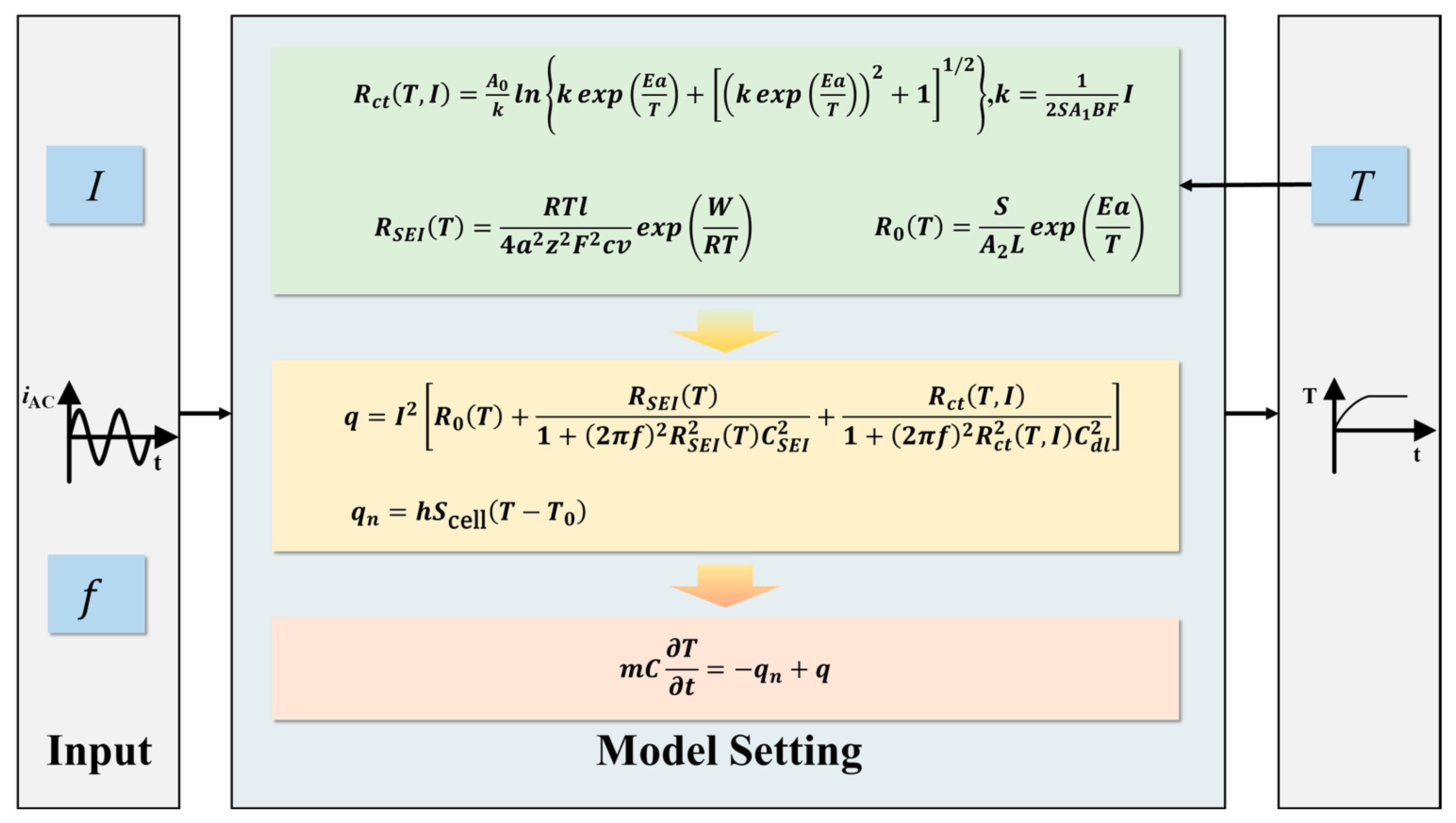
Classical heat transfer theory is applied to simulate the heat exchange occurring between the battery and its external environment. Additionally, the second-order equivalent circuit model is employed to simulate the heat production mechanism inside the battery. Figure 1 depicts a typical second-order equivalent circuit model (ECM), where UOCV represents the inherent open-circuit voltage of the battery. The ohmic impedance of the battery, denoted as R0, is primarily influenced by the active material, electrolyte, and contact conductivity, all of which vary with changes in battery temperature. The parallel circuit consisting of RSEI and CSEI simulates the passage of lithium ions through the solid–electrolyte interphase (SEI) during the charge and discharge processes. RSEI, which also exhibits a functional relationship with temperature, represents the equivalent resistance of the SEI, while CSEI stands for the equivalent capacitance of the SEI. Furthermore, the parallel circuit comprising R ct and C dl is utilized to simulate the charge transfer process. R ct represents the charge transfer resistance, which is influenced by both battery temperature and the current flowing through the battery, while C dl denotes the double-layer capacitor. These parameters and temperature are interrelated, achieving an electrothermal coupling, which forms the basis for us to establish the electrothermal model.
The battery utilized in this study features a compact size and cylindrical structure, enabling uniform heat transfer from its interior to the exterior. Consequently, it is reasonable to approximate that the surface temperature of the battery aligns with its internal temperature. Therefore, in this paper, the battery is regarded as an independent heat source with a uniform surface and internal temperature. The thermal state of the battery can be characterized using the classical heat transfer equation:
m C T t = q n + q
where t signifies the time elapsed, T denotes the Kelvin temperature of the battery, q n represents the heat lost or gained by the battery through external heat exchange, and q represents the heat generated by the battery itself through chemical reactions or charge and discharge processes.
It is assumed that the predominant mode of heat exchange between the battery and the environment is through convective heat transfer between the battery surface and the surrounding air. This heat transfer phenomenon can be mathematically described using the following equation:
q n = h S cell ( T T 0 )
The heat generated by the battery itself primarily stems from three factors: the ohmic internal resistance, the polarization internal resistance, and the heat associated with the charge and discharge chemical reactions. The heat production rate can be expressed as the sum of these three components, as shown in the following equation:
q = q ohm + q act + q rev
where q ohm is the ohmic heat, q ohm = I 2 [ R 0 ( T ) + R SEI ( T ) ] ; q act is the heat of polarization, q act = I 2 R ct ( T , I ) ; and q rev is the heat of a chemical reaction, q rev = I T Δ S nF .
The entropy change, denoted as ΔS, in the chemical reaction of the battery is closely associated with the state of charge (SOC) of the battery. During the AC heating process, the battery undergoes alternating SOCs and discharge within each cycle. However, due to the negligible change in the SOC of the battery within one cycle, the corresponding entropy change is nearly zero. Therefore, in this model, the heat change resulting from this particular aspect can be approximated as negligible and disregarded.
Based on the aforementioned derivation, accounting for the capacitance component in the ECM, the expression for the actual heating impedance, denoted as R Q , is given by Equation (4):
R Q ( T , I , f ) = R 0 ( T ) + R SEI ( T ) 1 + ( 2 π f ) 2 R SEI 2 ( T ) C SEI 2 + R ct ( T , I ) 1 + ( 2 π f ) 2 R ct 2 ( T , I ) C dl 2
where f represents the frequency of the excitation current. The total battery heat production rate can be simplified as
q = I 2 R Q ( T , I , f )
Relevant research [47] indicates that there is a decrease in R 0 , R SEI , and R ct as the temperature increases. Notably, the reduction rate of R ct is significantly higher compared to the first two parameters. Furthermore, at low temperatures, the equivalent resistance value of R ct is considerably greater than those of the other two. At temperatures below −20 °C, the equivalent resistance of R ct can be up to approximately ten times higher than those of the other two. These findings indicate that the charge transfer resistance, R ct , substantially influences the AC heating of the battery, particularly at low temperatures.
Based on Arrhenius’ empirical equation, R ct can be approximated by the following expression:
R ct ( T ) = A 0 exp ( E a T )
The relationship between impedance R ct and reaction current can be expressed as [48]
R ct ( I F ) = η I F
where I F represents the reaction current and η represents the overpotential of the battery embedding reaction. According to the Bulter–Volmer equation, the electrode reaction current I F can be expressed as follows:
I F = S B F k 0 [ exp ( a a F η R T ) exp ( a c F η R T ) ]
The electrochemical reaction rate constant k 0 can be expressed by Arrhenius’ equation as k 0 = A 1 exp ( Ea T ) , where a a and a c are the conversion coefficients of the positive and negative electrodes, respectively, and i 0 is the transfer current density.
For the impedance of the battery, the charge transfer resistance is much larger than the equivalent resistance of the other components. Therefore, the current I F flowing through R ct can be considered equivalent to the battery terminal current I . By substituting I F in Equation (7) as I , Equation (9) [48] is obtained, which represents the final expression of the charge transfer resistance.
R ct ( T , I ) = A 0 k ln { k exp ( E a T ) + [ ( k exp ( E a T ) ) 2 + 1 ] 1 / 2 } ,     k = 1 2 S A 1 B F I
The battery’s ohmic resistance, R 0 , can be determined using Arrhenius’ equation, which can be expressed as [48]
R 0 = S A 2 L exp ( E a T )
It is assumed that all potential drops occur on the SEI during lithium-ion migration. Therefore, the value of R SEI is smaller and can be approximated as
R SEI = R T l 4 a 2 z 2 F 2 c v exp ( W R T )
In summary, the mathematical expressions of the electro-thermal model for AC heating comprise Equations (1), (2), (4), (5), and (9)–(11).
The AC heating process is set to last between 10 and 20 min, with an initial temperature value of −20 °C and a heating target above 0 °C. If the excitation frequency is too high, the circuit requires a higher sampling frequency, processing speed, and switching frequency, placing excessive demands on the circuit. Conversely, if the frequency is too low, the internal resistance of the battery increases, limiting the current amplitude that can be applied to prevent lithium plating. Consequently, the heat production of the battery is reduced at low frequencies. Therefore, the frequency range of the excitation current is set between 20 and 200 Hz.
The boundary conditions for excitation current parameters are determined. In AC heating, when the terminal voltage at both ends of the battery fully meets the voltage-limiting conditions 3.2   V U 4.2   V , the battery life can generally be guaranteed without damage. As a boundary condition, the maximum current value that the battery can withstand at a specific temperature and excitation frequency can be calculated using the internal resistance equation (Equation (7)) derived above.
When heating, the initial voltage at both ends of the battery cell is uncontrollable. In this study, the initial voltage is between 3.4 and 4.0 V, covering more than 80% of the battery’s energy. At this time, the maximum value of the product of the battery’s internal resistance and the current amplitude cannot exceed the difference between the maximum battery voltage and the maximum initial battery voltage; specifically, it cannot exceed 0.2 V. The internal resistance of the battery in the heat production equation is calculated according to the final temperature value, while the internal resistance of the battery in the boundary equation is calculated according to the initial temperature value. The final normalization is shown as follows:
{ I R ( T MIN , I , f ) 0.2 V I 2 R ( T MAX , I , f ) = q L e t   q   b e   t h e   l a r g e s t

2.2. Model Simulation

Based on the equation derived in the preceding section, relevant battery data were researched, and a simulation model for a single 18650 batterywas established on the MATLAB R2019b/Simulink platform. The current magnitude and frequency were used as input variables, with temperature as the output. The simulation settings utilized a variable step size and the ode45 solver, as depicted in Figure 2. First, the initial parameters are set. Based on the mathematical model, the battery resistance value is calculated, and then the battery power dissipation and temperature rise are calculated. The output battery temperature variation is provided. According to the system output, the current is calculated and adjusted as a feedback loop to regulate the current amplitude. The feedback module uses the product of the current value in the circuit and the calculated battery resistance value to derive the voltage drop caused by the battery resistance. This voltage is then added to the open-circuit voltage of the battery model to determine the theoretical terminal voltage of the current battery. Accordingly, the output current amplitude is adjusted. Finally, the battery’s heat dissipation, temperature rise, and output battery temperature variation are calculated.
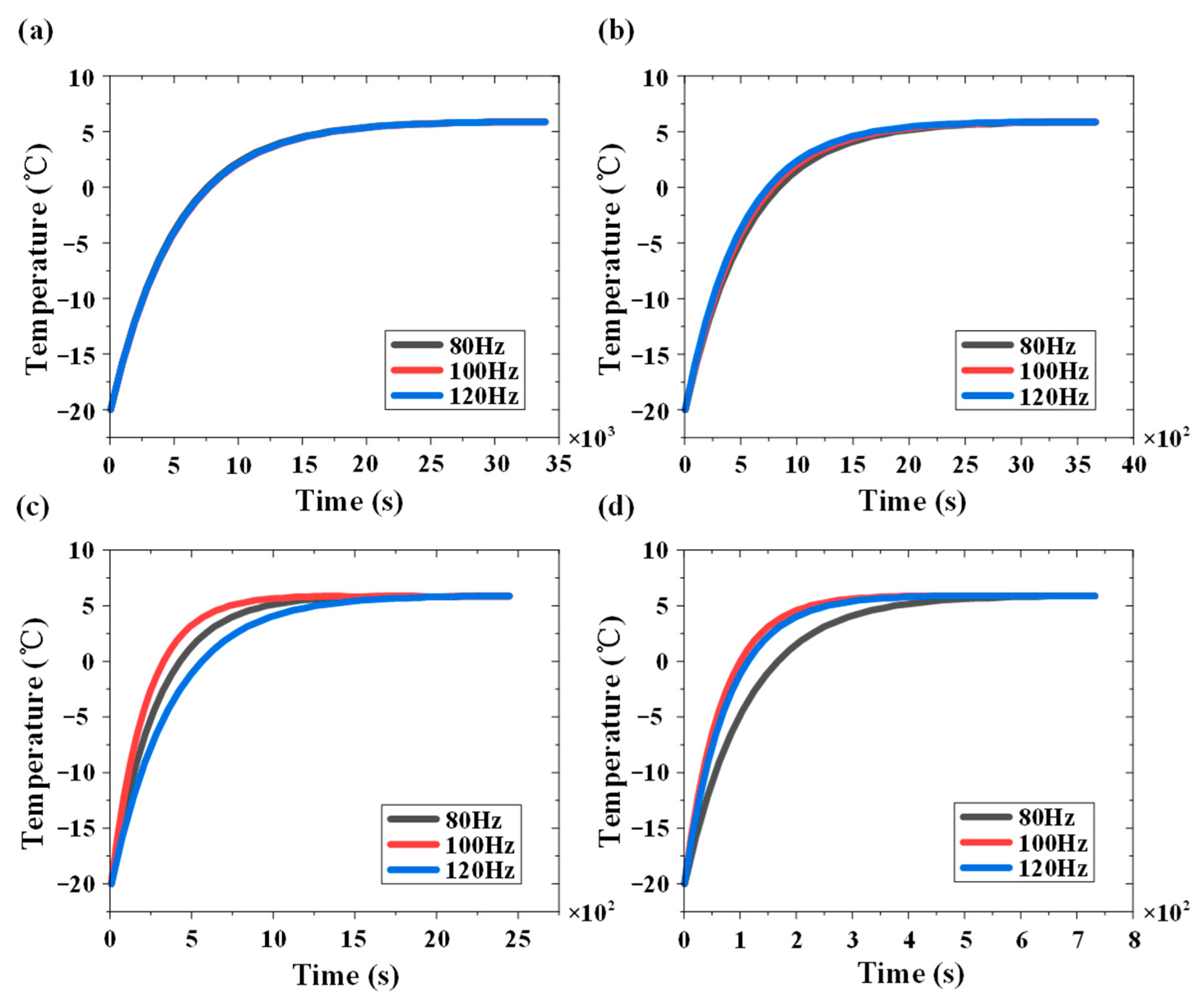
It is calculated that, at I = 10   A and f = 100   Hz , q takes an extreme value, at which point the heat generation is maximized, resulting in the most effective heating. Lithium-ion batteries exhibit capacitive characteristics, and the use of current waveforms with step-like characteristics, such as rectangular signals, may result in an excessive instantaneous impulse current in the circuit at the moment of current mutation. Therefore, the use of sine signals to stimulate the battery module is recommended. Figure 3 shows the simulation results of the AC heating model at currents of 1, 4, 7, and 10 A and frequencies of 80, 100, and 120 Hz, respectively. It can be observed that when the current is 1 A, the variation in excitation frequency from 80 to 120 Hz has little effect on the heating time, which remains significantly long. At a current of 4 A, heating is accelerated at an excitation frequency of 120 Hz, taking approximately 3400 s. Under 7 A, it is faster at an excitation frequency of 100 Hz, requiring about 1500 s. At 10 A, the fastest heating occurs at 100 Hz, reaching the desired temperature within 450 s and warming the lithium-ion battery from −20 to 6 °C; this set of working conditions is selected as the design parameter.

3. System Design

3.1. Design Requirement Analysis

The designed AC heating system will primarily cater to the application of electric bicycles in cold regions and expand to the battery swapping station scenario. Based on the analysis of the simulation model of heat production and temperature rise of AC heating in the previous section, the main input and output parameters of the designed hardware circuit are summarized in Table 2.

3.2. Topological Structure and Hardware Design

The design objective of the AC heating system proposed in this paper is to cater to both the electric bicycle usage scenario and the battery swapping scenario. Most of the DC/DC converters in high-power chargers adopt the circuit topology of a full-bridge circuit. Implementing AC heating based on the full-bridge circuit would facilitate integrated design with chargers. The circuit system structure is illustrated in Figure 4. In this study, the main circuit topology utilizes the full-bridge circuit. The control system primarily consists of an output current sampling circuit, an A/D conversion circuit, a full-bridge driver module, a communication module, and an MCU incorporating data storage and closed-loop control.
The selected MCU is the DSP digital signal processor TMS320C2812 from Texas Instruments. This study utilizes a four-way isolated power supply and driver IC for separate isolated driving. To convert the 3.3 V amplitude PWM wave into a 12 V amplitude with driving capability, the PWM wave needs to be isolated and output. The isolation chip used is the TLP250 optocoupler model produced by TOSHIBA Company.

3.3. Determination of Main Parameters

The selection parameters for each component are presented in Table 3.

3.4. Full-Bridge Topology Modeling

To investigate the frequency response characteristics of the system and provide guidance for control design, this study adopts the state-space method to model the full-bridge topology. The modeling process takes into account the presence of parasitic parameters, such as inductance, the output-side DC capacitor, and diodes in the switches. The system equivalent circuit used for state-space modeling is depicted in Figure 5.
Because the two H-bridges diagonally opposite the full bridge always switch on and off simultaneously, the current i L 1 varies with a period of T , while the current i 1 varies with a period of T 2 . Therefore, the analysis focuses on the current variation within the T 2 period to establish the state-space equations for the system. According to Kirchhoff’s law, in the system topology depicted in Figure 5 the following equation holds:
{ u C = e + z i L 2 + L 2 d i L 2 d t i L 1 = C d u C d t + i L 2 u u s = u C + L 1 d i L 1 d t
where u C represents the voltage across the filtering capacitor, e denotes the voltage across the output load, z signifies the load impedance, and u signifies the output voltage of the H-bridge.
The variable u s represents the switching function, which assumes different values depending on the states of the switches, as illustrated in Equation (13).
u s = { 1 ,     V 1   a n d   V 4   a r e   c o n n e c t e d 1 ,     V 2   a n d   V 3   a r e   c o n n e c t e d
Define i L 1 , i L 2 , and u C as state variables, with the output-side battery voltage treated as an external disturbance, resulting in the following state-space equations for the system.
{ x ˙ = [ d i L 1 d t d i L 2 d t d u C d t ] = [ 0 0 1 L 1 0 z L 2 1 L 2 1 C 1 C 0 ] [ i L 1 i L 2 u C ] + [ 1 L 1 0 0 ] u u s + [ 0 1 L 2 0 ] e y = [ 0 1 0 ] [ i L 1 i L 2 u C ]
Equation (14) describes a system with time-invariant coefficients, where the time-varying quantity is the output voltage of the H-bridge, denoted as the control input u . Within one switching cycle, the average value u ¯ of u can be given by Equation (15), where i s represents the specified reference current control input and k denotes the amplification factor of the reference input after PWM by the H-bridge. For an H-bridge with PWM producing bipolar outputs, k is the ratio of the H-bridge bus voltage to the triangular wave used for PWM, reflecting the H-bridge’s ability to “amplify” the given signal.
u ¯ = k i s
The transfer function from control input to output current is given by
I L 2 ( s ) = k I s ( s ) ( C L 1 s 2 + 1 ) E ( s ) C L 1 L 2 s 3 + C L 1 Z s 2 + ( L 1 + L 2 ) s + Z
For a battery, its external characteristics can be approximated using a first-order RC equivalent circuit model. The equivalent capacitance in this model typically has a very large value, and the parallel RC section significantly affects the low-frequency characteristics of the system. At high frequencies, the analysis can approximate the battery as a resistive load with Z = 0.1   Ω .

3.5. System Control Strategy

This paper presents a closed-loop control strategy employing the PR control algorithm to regulate the output current. The designed AC heating system demonstrates a notable DC voltage bias in the output load. To tackle this issue, an integration link is integrated at low frequencies to amplify the amplitude gain of the quasi-PR controller and adequately mitigate the influence of the DC voltage. The improved PR controller is formulated as Equation (17):
G ( s ) = K P + 2 K R ω c s s 2 + 2 ω c s + ω 0 2 + K I s
where K p represents the proportional term coefficient, K R denotes the resonance term coefficient, ω 0 stands for the resonance frequency, ω c is an adjustable parameter that influences both the gain of the PR controller and the bandwidth of the controller cutoff frequency, and K I indicates the integral term coefficient.
The continuous quasi-PR controller is discretized using the bilinear transformation method. Through the application of this transformation and leveraging the connection between the Z-domain transfer function and the difference equation, the difference equation can be derived as
y ( k ) = 1 3 [ ( K P + b 0 + c 0 ) x ( k ) + c 0 x ( k 1 ) b 0 x ( k 2 ) + ( 2 y a 1 ) y ( k 1 ) a 2 y ( k 2 ) ]
where the parameters ω 0 , ω C , T , and K R are predetermined, and the values of b 0 , a 1 , and a 2 can be calculated directly. In the digital controller, discrete quasi-PR control is realized using a difference equation.
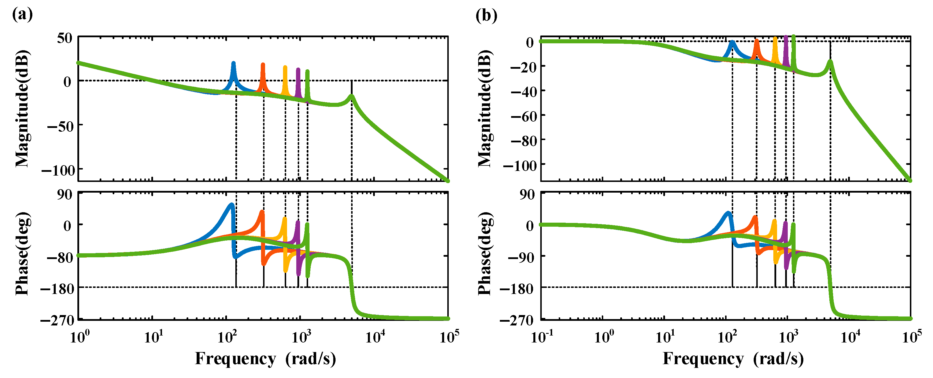
Considering the H-bridge gain, the capacitance and inductance values are substituted, and incorporating the improved quasi-PR controller yields the open-loop and unit negative feedback Bode plots of the system under K P = 0.01 , K R = 0.5 , K I = 0.5 , and ω c = 1 , as shown in Figure 6. It is observed that as the output frequency of the system increases, the gain at the specified frequency is greater than 0. At low frequencies, there is a gain of approximately 25 dB. This indicates that the improved quasi-PR controller meets the output characteristic requirements of the AC excitation device.

3.6. System Simulation

Using MATLAB R2019b/Simulink simulation, the selected components, such as the switch devices in the full-bridge circuit and the output filter circuit, are constructed based on the model and parameters specified in this paper. The data for each switch tube or diode are sourced from the official data manual of the IR company from Los Angeles, CA, USA. Various parasitic parameters are configured in the model according to the values provided in the manual. In this module, the duty cycle of each PWM at the next instance is calculated based on the error between the current value and the expected current value in the circuit, utilizing the PR algorithm. The PWM module generates the corresponding duty cycle PWM based on the output of the PR control module. The main circuit topology consists of the full-bridge circuit, the LCL filter circuit, and the output battery module.
To validate the circuit’s capability to produce excitation current within the specified range, the amplitude and frequency of the output current target are adjusted accordingly. As per the design specifications outlined in this paper, achieving the desired output amplitude entails ensuring that the frequency of the output current falls within the required range. By simulating the output current at the prescribed limit values, both the output capacity and characteristics can be ascertained.
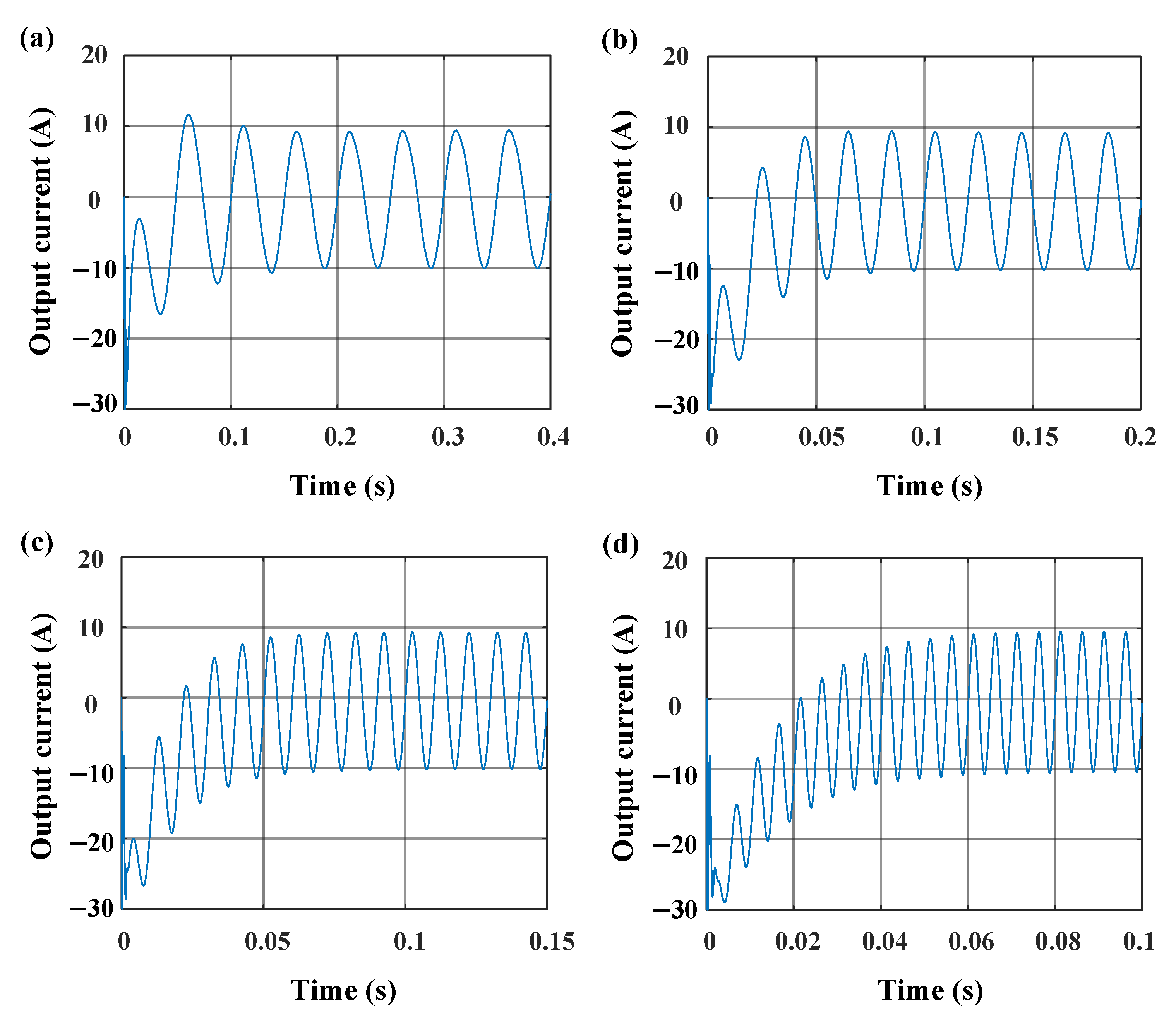
Figure 7 depicts the system simulation output current waveforms of 20, 50, 100, and 200 Hz at 10 A. When the excitation frequency is 20 Hz, the simulated system output current reaches a stable state in 0.1 s. When it is increased to 50 Hz, the stabilization time is shortened to 0.06 s. As it is further increased to 100 and 200 Hz, the system stabilization time remains at around 0.06 s. Notably, when it is 20 Hz, the system output can reach a stable state within the first three cycles. It can be seen that a good waveform control effect can be achieved under different frequency settings, and the response time of the control system is also faster. According to the simulation, based on the improved quasi-PR controller closed-loop control method combined with the full-bridge circuit topology, the design requirements of the lithium-ion battery module in this paper can be realized.

4. Experimental Section

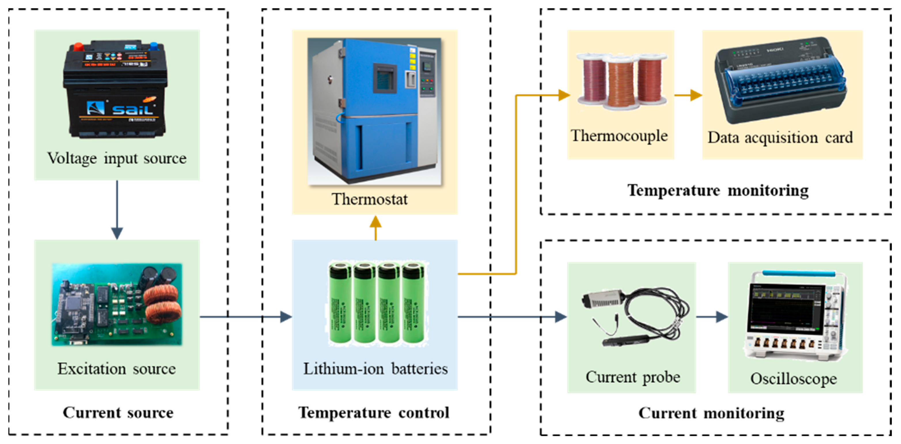
The output load of the AC heating system comprised six 18650 lithium-ion batteries arranged in series. For the input, a 36 V DC-regulated power supply was employed, which consists of three 12 V lead–acid batteries and a diode connected in series. Due to the absence of a battery management system that can interface with the system, the amplitude and frequency of the output current were fixed during the verification of the efficacy of the AC heating system. Changes in battery temperature were monitored and recorded using an independent temperature-monitoring device. The influence of the AC heating system on the performance of the target lithium-ion battery during operation was assessed by analyzing the variation in the battery’s internal resistance before and after multiple AC heating experiments. Figure 8 illustrates the prototype of the AC heating system and the test platform, with thermocouples affixed to the battery surface using specialized stickers.
High-voltage input source: Fengfan 46B24L-MF lead–acid battery. Low-voltage input source: DF17315C3A, a dual-channel constant-current constant-voltage controllable power supply manufactured by Ningbo Zhongce Company. Oscilloscope: Tektronix DP03054 model. Voltage probe: Tektronix P6139B high-voltage probe. Current probe: Tektronix TCP0020 current probe. Thermostat: Shanghai Dongda Company’s T-TH-225-C high- and low-temperature alternating wet and heat test chamber. Temperature sensor: American Omega company’s TT-T-36-SLE thermocouple wire. Data acquisition card: Japan Nippon Company’s LR8510 wireless voltage and temperature unit data acquisition instrument. Current pulse excitation source: Arbin BT2000 electronic load. Host computer: Texas Instruments’ CCStudio, a dedicated DSP debugging software version v3.3.
To simulate a low-temperature environment of −20 °C, the lithium-ion battery module was placed within the thermostat, gradually reducing its temperature to match the ambient −20 °C. A thermocouple was attached to the surface of a single battery within the module, with the temperature changes monitored and recorded by the sampling monitoring module. The thermocouples were placed on the surface of the third cell in the battery pack. Since the six cells were connected in series, the current flowing through each cell was the same. Additionally, the entire system was placed in a temperature chamber, ensuring consistent environmental conditions. Therefore, the temperature of a single cell was measured to represent the temperature of the entire battery module. By applying 100 Hz, 10 A excitation to the module with the designed prototype, it was observed whether the battery module could raise the temperature of the lithium-ion battery to above 0 °C within 20 min. The experiment was repeated 20 times, and the internal resistance of the battery was measured at room temperature at the beginning and end of the test to verify the effect on the life of the lithium-ion battery.

5. Results and Discussion

5.1. System Verification

5.1.1. Verification of Current Control Effect

Closed-loop regulation analysis is mainly used to verify the control effect of closed-loop control, including current closed-loop response analysis. In the closed-loop response analysis of the current test, the initial current amplitude is set to 2 A at a frequency of 100 Hz, and subsequently adjusted to 10 A. As depicted in Figure 9, the actual change in current during the test reveals that the closed-loop response time for current is 70 ms, with a calculated steady-state error of 1%. Because the AC heating of the battery is a long-timescale process relative to the response time, and its time can generally reach several minutes or even tens of minutes, the requirement for its adjustment time is not high—the amplitude accuracy of its output current is mainly required—and the steady-state error in the test is 1%, which can fully meet the needs of practical applications.

5.1.2. Heating Effect Verification

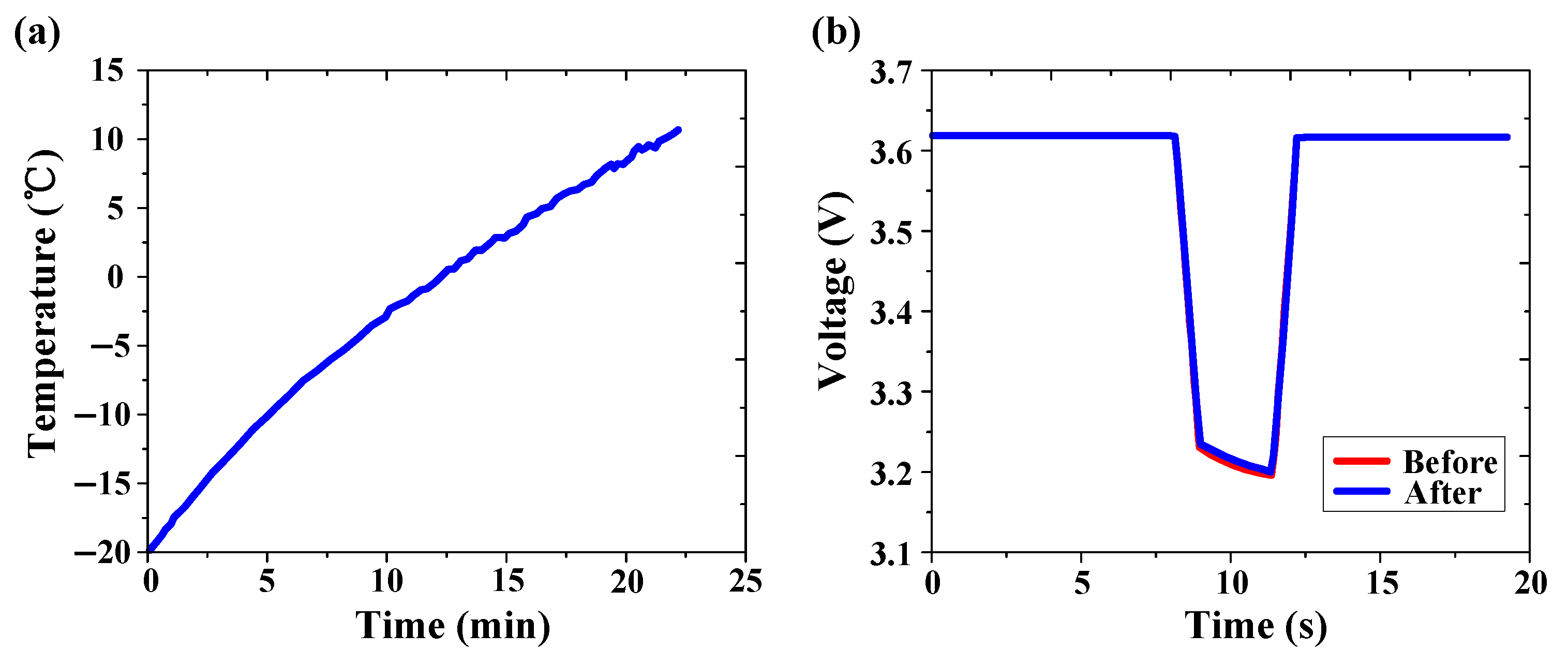
Figure 10a illustrates the variation in surface temperature of the lithium-ion battery during a test. It is evident that the prototype successfully applies AC excitation continuously to the lithium-ion battery even at low temperatures. The lithium-ion battery exhibits an increase in temperature from −20 to 6 °C within the 20-min duration. At this temperature, the lithium-ion battery satisfies the requirements for charge and discharge operating temperatures.
Figure 10b presents the changes in the internal resistance of the lithium-ion batteries detected by applying a short-time pulse current to the lithium-ion battery module before and after 20 tests, thereby characterizing the degree of battery aging. These internal resistance tests were conducted at room temperature and an SOC of 50%. The red curve represents the initial state of the battery, while the blue curve depicts the test results after subjecting the battery to the same excitation following 20 AC heating tests. The experimental findings indicate that after 20 tests, the internal resistance of the lithium-ion batteries exhibits almost no change, suggesting no loss of life. Consequently, the prototype devised in this study effectively heats the lithium-ion battery module with AC excitation, fulfilling the design requirements.

6. System Implementation

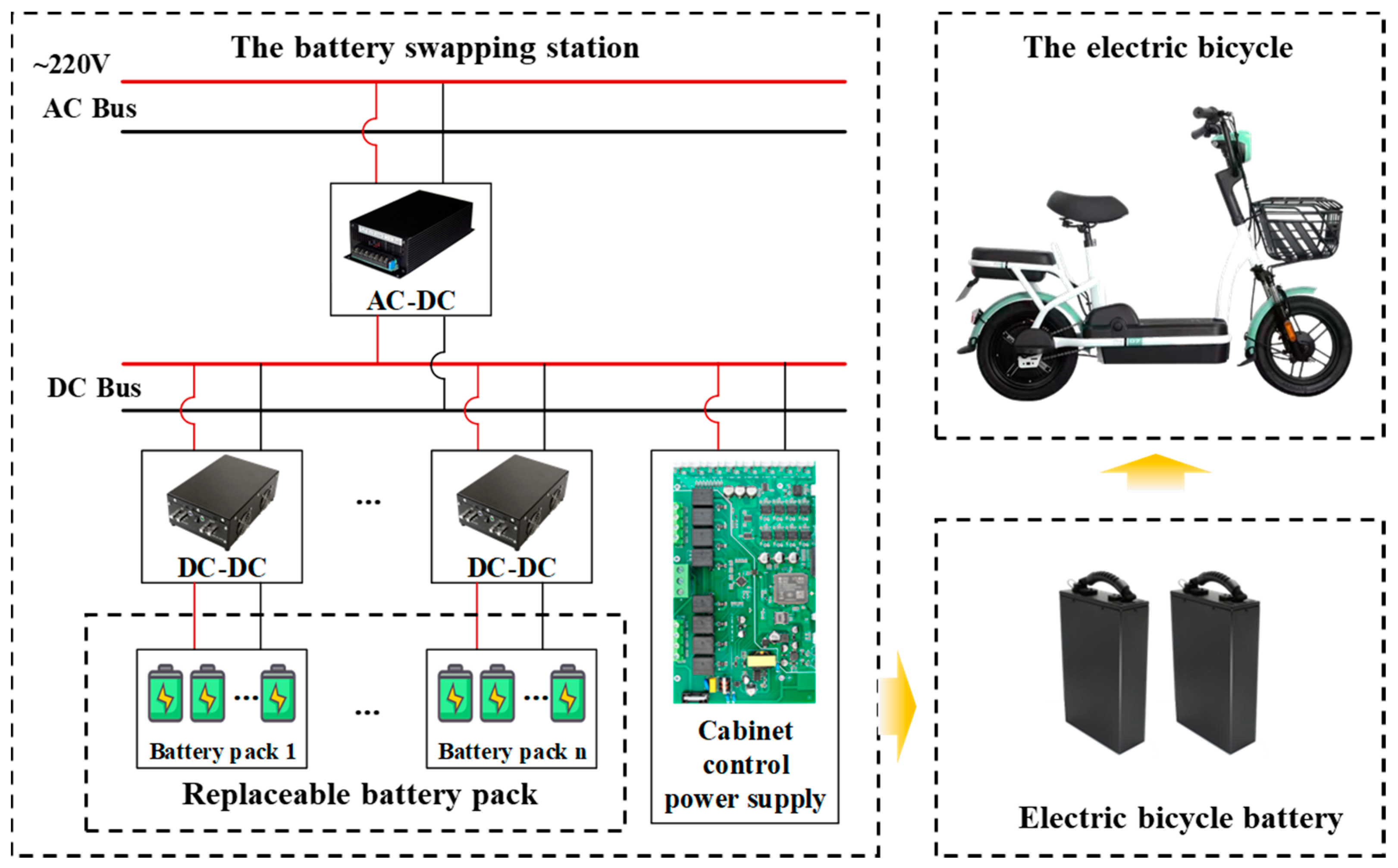
The low-temperature lithium-ion battery heating system proposed in this paper not only fulfills the heating requirements during electric bicycle charging but can also be integrated into electric bicycle lithium-ion battery swapping cabinets to mitigate the security risks associated with low-temperature charging. Figure 11 illustrates the system implementation diagram.

7. Conclusions

This paper presents a design of a prototype system based on full-bridge topology to enhance the charging and discharging performance of onboard lithium-ion batteries in electric bicycles during low-temperature conditions. To validate the effectiveness of the control strategy, a full-bridge topology system model was constructed and implemented. The system is equipped to perform AC heating on lithium-ion battery modules. To analyze the heating effect of AC excitation on lithium-ion batteries, a comprehensive set of simulation models, integrating heat transfer and battery mechanism analysis, was developed and utilized for both normal use and battery swapping scenarios.
By employing a current closed-loop control strategy, the prototype can generate sinusoidal currents with a frequency ranging from 20 to 200 Hz and a maximum amplitude of 10 A. When connected to an external battery, the current ripple of the output current remains below 5%, ensuring a high degree of output current accuracy approaching 1%. Demonstrating its efficacy, the prototype is capable of elevating the temperature of 18650 batteries from −20 to 6 °C within a mere 20-min timeframe, adequately fulfilling the requirements of the heating system by swiftly raising the lithium-ion battery’s temperature from subzero to near-zero levels. Moreover, the prototype exhibits outstanding closed-loop current control, boasting a remarkably swift control response time of only 70 ms. In future function optimizations, the prototype can be enhanced to facilitate variable-amplitude and variable-frequency excitation heating, thereby better catering to diverse application requirements. Additionally, it allows for the adjustment of output current amplitude and frequency through closed-loop control, enabling real-time adaptation to various batteries and excitation strategies.

Author Contributions

Conceptualization, Q.X.; Methodology, Q.X., X.W. (Xueyuan Wang) and X.W. (Xuezhe Wei); Software, Q.X.; Validation, Q.X.; Formal Analysis, Q.X., W.F. and X.W. (Xueyuan Wang); Investigation, W.F.; Resources, X.W. (Xuezhe Wei) and H.D.; Writing—Original Draft Preparation, Q.X.; Writing—Review and Editing, Q.X., X.W. (Xueyuan Wang), X.W. (Xuezhe Wei) and W.F.; Supervision, H.D.; Project Administration, X.W. (Xuezhe Wei) and H.D.; Funding Acquisition, H.D. All authors have read and agreed to the published version of the manuscript.

Funding

This research was funded by the National Natural Science Foundation of China (Grant numbers 52207242 and U20A20310).

Data Availability Statement

The authors are unable or have chosen not to specify which data have been used.

Conflicts of Interest

The authors declare no conflicts of interest.

References

  1. Zhao, L.; Shen, S.; Zhao, Z. Planning decentralized battery-swapping recharging facilities for e-bike sharing systems. Sustain. Cities Soc. 2024, 101, 105118. [Google Scholar] [CrossRef]
  2. Xie, X.; Dai, X.; Pei, Z. Empowering the Capillary of the Urban Daily Commute: Battery Deployment Analysis for the Locker-Based E-bike Battery Swapping. Transp. Sci. 2024, 58, 176–197. [Google Scholar] [CrossRef]
  3. Ahmad, F.; Alam, M.S.; Alsaidan, I.S.; Shariff, S.M. Battery Swapping Station for Electric Vehicles: Opportunities and Challenges. Iet Smart Grid 2020, 3, 280–286. [Google Scholar] [CrossRef]
  4. Zhang, S.S.; Xu, K.; Jow, T.R. Charge and Discharge Characteristics of a Commercial LiCoo2-Based 18650 Li-ion Battery. J. Power Sources 2006, 160, 1403–1409. [Google Scholar] [CrossRef]
  5. Sun, B.; Qi, X.; Song, D.; Ruan, H. Review of Low-Temperature Performance, Modeling and Heating for Lithium-Ion Batteries. Energies 2023, 16, 7142. [Google Scholar] [CrossRef]
  6. Elbuluk, M.E.; Hammoud, A.; Gerber, S.; Patterson, R.L. Low Temperature Performance Evaluation of Battery Management Technologies. In Proceedings of the 34th Intersociety Energy Conversion Engineering Conference, Vancouver, BC, Canda, 2–5 August 1999; pp. 313–318. [Google Scholar]
  7. Zhang, S.S.; Xu, K.; Jow, T.R. The Low Temperature Performance of Li-Ion Batteries. J. Power Sources 2003, 115, 137–140. [Google Scholar] [CrossRef]
  8. Fan, W.; Zhu, J.; Qiao, D.; Jiang, B.; Wang, X.; Wei, X.; Dai, H. Low-Temperature Charging Strategy Optimization Based on Electrochemical-Aging-Thermal Coupling Model. IEEE Trans. Transp. Electrif. 2024, 1, 35. [Google Scholar] [CrossRef]
  9. Wankhede, S.; More, K.; Kamble, L. A Review of Li-ion Battery Temperature Control and A Key Future Perspective on Cutting-Edge Cooling Methods For Electrical Vehicle Applications. Energy Storage 2024, 6, e572. [Google Scholar] [CrossRef]
  10. Kulova, T.L.; Skundin, A.M.; Nizhnikovskii, E.A.; Fesenko, A.V. Temperature Effect on the Lithium Diffusion Rate in Graphite. Russ. J. Electrochem. 2006, 42, 259–262. [Google Scholar] [CrossRef]
  11. Hein, S.; Latz, A. INFLUENCE of Local Lithium Metal Deposition in 3D Microstructures on Local and Global Behavior of LITHIUM-ion Batteries. Electrochim. Acta 2016, 201, 354–365. [Google Scholar] [CrossRef]
  12. Janakiraman, U.; Garrick, T.R.; Fortier, M.E. Review-Lithium Plating Detection Methods in Li-Ion Batteries. J. Electrochem. Soc. 2020, 167, 160552. [Google Scholar] [CrossRef]
  13. Suthar, B.; Sonawane, D.; Braatz, R.D.; Subramanian, V.R. Optimal Low Temperature Charging of Lithium-ion Batteries. In Proceedings of the 9th IFAC Symposium on Advanced Control of Chemical Processes ADCHEM 2015, Whistler, CA, USA, 7–10 June 2015; pp. 1216–1221. [Google Scholar]
  14. Huang, R.; Wei, G.; Zhou, X.; Zhu, J.; Pan, X.; Wang, X.; Jiang, B.; Wei, X.; Dai, H. Targeting the Low-Temperature Performance Degradation of Lithium-Ion Batteries: A Non-Destructive Bidirectional Pulse Current Heating Framework. Energy Storage Mater. 2024, 65, 103173. [Google Scholar] [CrossRef]
  15. Jaguemont, J.; Boulon, L.; Venet, P.; Dubé, Y.; Sari, A. Lithium-Ion Battery Aging Experiments at Subzero Temperatures and Model Development for Capacity Fade Estimation. IEEE Trans. Veh. Technol. 2016, 65, 4328–4343. [Google Scholar] [CrossRef]
  16. Kim, R.; Kim, Y.; Lee, D.H.; Kim, S.; Kim, D.K. Thermal-Electrochemical Effect on the Degradation of Lithium-Ion Batteries During the Charging Process. Int. Commun. Heat Mass Transf. 2024, 158, 107855. [Google Scholar] [CrossRef]
  17. Wei, G.; Zhang, G.; Chen, S.; Jiang, B.; Zhu, J.; Han, G.; Wei, X.; Dai, H. Experimental Study on Effect of State of Charge on Thermal Runaway Characteristics of Commercial Large-Format NCM811 Lithium-Ion Battery; SAE International: Warrendale, PA, USA, 2023. [Google Scholar]
  18. Thakur, A.K.; Sathyamurthy, R.; Velraj, R.; Saidur, R.; Pandey, A.K.; Ma, Z.; Singh, P.; Hazra, S.K.; Sharshir, S.W.; Prabakaran, R.; et al. A State-of-the Art Review on Advancing Battery Thermal Management Systems for Fast-charging. Appl. Therm. Eng. 2023, 226, 120303. [Google Scholar] [CrossRef]
  19. Siruvuri, S.D.V.S.S.V.; Budarapu, P.R. Studies on Thermal Management of Lithium-Ion Battery Pack Using Water as the Cooling Fluid (Article). J. Energy Storage 2020, 29, 101377. [Google Scholar] [CrossRef]
  20. Amy, C.; Pishahang, M.; Kelsall, C.C.; LaPotin, A.; Henry, A. High-temperature Pumping of Silicon for Thermal Energy Grid Storage. Energy 2021, 233, 121105. [Google Scholar] [CrossRef]
  21. Yao, J.; Wang, Z.; Ma, J. Dehydration Method for Lithium ion Battery Core, Involves Pulsating High-Temperature Gas Circulating via Circulation Device Connected With Sealed Container and Extracting High-Temperature Gas for Reducing Internal Pressure of Container; Shandong Sacred Sun Power Sources Co., Ltd. (SHAN-Non-standard): Yantai, China, 2016. [Google Scholar]
  22. Ross, M.; Lin, T.Y.; Wicoff, I.; Sieh, B.; Sabharwall, P.; McEligot, D.E.; Bindra, H. Passive Heat Removal in Horizontally Oriented Micro-HTGRs. Prog. Nucl. Energy 2023, 156, 104530. [Google Scholar] [CrossRef]
  23. Lei, Z.; Zhang, C.; Dong, Y.; Lin, Z. Low-Temperature Performance and Heating Method of Lithium Battery in Electric Vehicles. Beijing Gongye Daxue Xuebao/J. Beijing Univ. Technol. 2013, 39, 1399. [Google Scholar]
  24. Zhang, S.; Li, T.; Chen, L. Fuzzy Logic Control of External Heating System for Electric Vehicle Batteries at Low Temperature. World Electr. Veh. J. 2023, 14, 99. [Google Scholar] [CrossRef]
  25. Nolte, O.; Heim, U. Temperature Control Element for Battery, Which Drives Electric Vehicle, Has Ptc Heating Element for Heating Element, and Base Surface Provided in Element, Which Transfers Heat between Element and Battery Module of Battery; Porsche Ag F (Pors-C) Volkswagen Ag (Vols-C): Wolfsburg, DE, USA, 2018. [Google Scholar]
  26. Sarvar-Ardeh, S.; Rashidi, S.; Rafee, R.; Karimi, N. A Review on the Applications of Micro-/Mini-Channels for Battery Thermal Management. J. Therm. Anal. Calorim. 2023, 148, 7959–7979. [Google Scholar] [CrossRef]
  27. Zhang, L.; Zhao, H.; Liang, S.; Liu, C. Heat Transfer in Phase Change Materials for Integrated Batteries and Power Electronics Systems. Appl. Therm. Eng. 2023, 232, 120997. [Google Scholar] [CrossRef]
  28. Gao, C.; Sun, K.; Song, K.; Zhang, K.; Hou, Q. Performance Improvement of a Thermal Management System for Lithium-Ion Power Battery Pack by the Combination of Phase Change Material and Heat Pipe. J. Energy Storage 2024, 82, 110512. [Google Scholar] [CrossRef]
  29. Sevugan, P.A.; Pradeep, M.; Krishnaswamy, A.; Karunamurthy, K. Battery Thermal Management System for electric vehicles using Phase Change Materials. In Proceedings of the 2nd International Conference on Sustainable Energy Solutions for a Better Tomorrow (SESBT), Vellore Inst Technol, Chennai, India, 23–24 July 2021; pp. 1604–1611. [Google Scholar]
  30. Upadhyay, D.; Mujadia, V.; Daruwala, R.; Lakdawala, A.; Shah, D.V. Investigation on Performance of Composite Phase Change Material Based Thermal Management of Electrical Battery. Int. J. Interact. Des. Manuf. 2024, 1, 1–10. [Google Scholar] [CrossRef]
  31. Huang, R.; Wei, G.; Jiang, B.; Zhu, J.; Pan, X.; Wang, X.; Zhou, X.; Ye, J.; Wei, X.; Dai, H. Investigating the Effect of Different Bidirectional Pulsed Current Parameters on the Heat Generation of Lithium-Ion Battery at Low Temperatures. Batteries 2023, 9, 457. [Google Scholar] [CrossRef]
  32. Ruan, H.; Jiang, J.; Sun, B.; Zhang, W.; Gao, W.; Wang, L.; Ma, Z. A Rapid Low-Temperature Internal Heating Strategy with Optimal Frequency Based on Constant Polarization Voltage for Lithium-Ion Batteries. Appl. Energy 2016, 177, 771–782. [Google Scholar] [CrossRef]
  33. Stuart, T.A.; Hande, A. HEV Battery Heating Using AC Currents. J. Power Sources 2004, 129, 368–378. [Google Scholar] [CrossRef]
  34. Qu, Z.; Jiang, Z.; Wang, Q. Experimental Study on Pulse Self–Heating of Lithium–ion Battery at Low Temperature. Int. J. Heat Mass Transf. 2019, 135, 696–705. [Google Scholar] [CrossRef]
  35. Arvind, S.; Naik, S.; Sirisha, T.; Madhavi, P.; Ogeti, P.S.; Tharun, O.; Praneeth, D.; Uday, B.; Rakesh, P.; Satyanarayana, S.V. Electric Tricycle I.E. Hybrid Tricycle for Used by Physically-Handicapped People, Has Smart Starter System Comprising Hub Motor Kit, Battery Pack, Li-Ion Battery Charger Pack, Arduino Uno, Lm35 Sensor, Cooling Fans and Sine Wave Controller; Hyderabad Technology & Management Inst. (HYDE-Non-standard): Hyderabad, India, 2024. [Google Scholar]
  36. Geun, P.J. Charger Air Cooling Structure of Portable Terminal for Two-Wheeled Vehicle E.G. Motorcycle, Has Heat Dissipation Fins That Are Attached to Substrate of Circuit Structure and Positioned in Second Air Chamber; GEUN P J. (GEUN-Individual): Seoul, Republic of Korea, 2022. [Google Scholar]
  37. Ok, K.K.; Kim, K.S. Charger for Electric Transport Device E.G. Electric Bicycle, Has Cooling Fan That Is Provided inside Main Portion to Cool First Charging Unit and Second Charging Unit, and Vent Hole through Which Air Moves by Cooling Fan Is Formed Outside Main Portion; HYUNDAI EVC. (HYUN-Non-standard): Seoul, Republic of Korea, 2022. [Google Scholar]
  38. Meyers, J.P.; Doyle, M.; Darling, R.M.; Newman, J.S. The Impedance Response of a Porous Electrode Composed of Intercalation Particles. J. Electrochem. Soc. 2000, 147, 2930–2940. [Google Scholar] [CrossRef]
  39. Doyle, M.; Newman, J.; Gozdz, A.S.; Schmutz, C.N.; Tarascon, J.M. Comparison of Modeling Predictions with Experimental Data from Plastic Lithium Ion Cells. J. Electrochem. Soc. 1996, 143, 1890. [Google Scholar] [CrossRef]
  40. Doyle, M.; Fuller, T.F.; Newman, J. Modelling the Galvanostatic Charge and Discharge of the Lithium/Polymer/Insertion Cell. J. Electrochem. Soc. 1992, 140, 1526–1533. [Google Scholar] [CrossRef]
  41. Chung, K.-i.; Chung, M.-W.; Kim, W.-S.; Kim, S.-K.; Sung, Y.-E.; Choi, Y.-K. Studies of the Passivation Film as a Function of the Concentration of Electrolyte in Lithium-Ion Battery. Bull. Korean Chem. Soc. 2001, 22, 189–193. [Google Scholar]
  42. Kim, G.-H.; Pesaran, A.; Spotnitz, R. A Three-Dimensional Thermal Abuse Model for Lithium-Ion Cells. J. Power Sources 2007, 170, 476–489. [Google Scholar] [CrossRef]
  43. Panasonic Ncr18650b. Available online: https://batterybro.com/products/panasonic-b-ncr18650b-3400mah-4-8a (accessed on 4 December 2023).
  44. Hatchard, T.D.; MacNeil, D.D.; Basu, A.; Dahn, J. Thermal Model of Cylindrical and Prismatic Lithium-Ion Cells. J. Electrochem. Soc. 2001, 148, A755–A761. [Google Scholar] [CrossRef]
  45. Momma, T.; Matsunaga, M.; Mukoyama, D.; Osaka, T. AC Impedance Analysis of Lithium Ion Battery Under Temperature control (Article). J. Power Sources 2012, 216, 304–307. [Google Scholar] [CrossRef]
  46. Han, X.; Ouyang, M.; Lu, L.; Li, J. Simplification of Physics-Based Electrochemical Model for Lithium Ion Battery on Electric Vehicle. Part i: Diffusion Simplification and Single Particle Model. J. Power Sources 2015, 278, 802–813. [Google Scholar] [CrossRef]
  47. Zhang, G.; Wei, X.; Chen, D.; Wang, X.; Chen, S.; Zhu, J.; Dai, H. Thermal Characteristic Evolution of Lithium–Ion Batteries during the Whole Lifecycle. J. Energy Chem. 2024, 92, 534–547. [Google Scholar] [CrossRef]
  48. Zhuang, Q.; Yang, Z.; Zhang, L.; Cui, Y. Diagnosis of Electrochemical Impedance Spectroscopy in Lithium Ion Batteries. Prog. Chem. 2020, 32, 761–791. [Google Scholar] [CrossRef]
Figure 1. Second-order equivalent circuit model of a lithium-ion battery.
Batteries 10 00300 g001
Figure 2. AC heating model simulation model.
Batteries 10 00300 g002
Figure 3. The simulation results of the AC heating model at currents of (a) 1, (b) 4, (c) 7, and (d) 10 A.
Batteries 10 00300 g003
Figure 4. The structure of the circuit system.
Batteries 10 00300 g004
Figure 5. The circuit used for state-space system modeling.
Batteries 10 00300 g005
Figure 6. (a) The open-loop Bode plot; (b) the unit negative feedback Bode plot of the system using the improved quasi-PR controller.
Batteries 10 00300 g006
Figure 7. System simulation output current waveforms of (a) 20, (b) 50, (c) 100, and (d) 200 Hz at 10 A.
Batteries 10 00300 g007
Figure 8. AC heating system and test platform.
Batteries 10 00300 g008
Figure 9. Current closed-loop response analysis.
Batteries 10 00300 g009
Figure 10. (a) Diagram of rise in battery module AC heating test temperature; (b) battery pulse excitation response before and after AC heating test.
Batteries 10 00300 g010
Figure 11. The system implementation diagram.
Batteries 10 00300 g011
Table 1. The AC heating model parameters.
ParameterValueUnitDescription
a 90 [38]pmthe ion jumping half distance
A 0 0.421 [39]--pre-exponential factor
A 1 0.392 [40]--pre-exponential factor
A 2 0.450 [40]--pre-exponential factor
B 1000 [41]mol/m3the lithium-ion concentration function in the battery
c 1500 [40]mol/m3the ion concentration
C 1319.9 [42]J/(kg∙K)the specific heat capacity of the lithium-ion battery
C a 2.94 [43]Cthe maximum charge C-rate
C i 3.4 [43]Ahthe capacity of the lithium-ion battery
E a 3.168 [38]kJ/molactivation energy
F 96,487C/molFaraday’s constant
h 16 [44]W/(m2·K)the equivalent heat transfer coefficient
l 120 [44]nmthe thickness of the SEI
m 49.5 [43]gthe mass of the lithium-ion battery
r 21 [45]the resistance of the lithium-ion battery
R 8.314J/(mol∙K)the ideal gas constant
S 0.05 [46]m2the effective area of the electrode
S cell 0.0043 *m2the battery surface area
T 0 279.15 *Kthe target Kelvin’s temperature
v 1013 [40]Hzthe lattice vibration frequency
V 3.6 [40]Vthe nominal voltage of the lithium-ion battery
W 1.12 [40]eVan ion jumping energy barrier
z 1Cthe ionic charge
* Calculated or designed parameters.
Table 2. AC heating hardware circuit input and output target parameters.
Target ParametersValue and Unit
input voltage36 V
output voltage25 V
maximum output current value10 A
output current frequency range20~200 Hz
output current waveformSine
switching frequency10 kHz
Table 3. Main component parameter table.
ComponentModelParameter
switching devicesIRF540N MOSFET f H B r i d g e = 10 kHz
the filter circuit at the output endLCL filterinput voltage U a = 36 V
output current I s = 10 A
switching frequency f s = 10 kHz
rated output voltage U s = 20 V
input-side inductance-- L 1 = 300 μH
input filter capacitor-- C = 470 μF
output-side inductance-- L 2 = 75 μH
input capacitance-- V = 75 V
C i = 1000 μF
Disclaimer/Publisher’s Note: The statements, opinions and data contained in all publications are solely those of the individual author(s) and contributor(s) and not of MDPI and/or the editor(s). MDPI and/or the editor(s) disclaim responsibility for any injury to people or property resulting from any ideas, methods, instructions or products referred to in the content.