1. Introduction
The effects of environmental pollution and global warming on our planet and society have meant that there is significant momentum towards the replacement and elimination of fossil fuels from the transportation and energy sectors. In combination with the growing global energy demand, the search for the replacement of sustainable renewable energy solutions is imperative [
1].
The hydrogen economy is considered to play a key role in the transition to alternative fuels as a long-term secure energy source. In addition to its eco-friendliness, green hydrogen is a preferred candidate in applications such as heavy and long-distance transport, energy-intensive heat, and power generators as well as backup capacity for grid electrical supply [
2]. Additionally, hydrogen is not only the most abundant element in the universe but also has the highest energy per unit mass of any fuel, seven times more than coal and three times more than gasoline and natural gas [
3,
4]. According to the European hydrogen vision, it is anticipated that by 2050 a hydrogen economy will have been established in the micro-applications, automotive, aviation, and distributed power generation sectors [
5]. Therefore, the availability and low cost of green hydrogen as an energy storage/transfer material will greatly facilitate the future decarbonization of many industrial processes.
Hydrogen as an energy source can be deployed in two distinct ways, i.e., by electrochemical fuel cells or by combustion either in thermal boilers or engines [
6]. Fuel cells are devices that enable direct and efficient energy conversion between hydrogen and electrical energy. When combined with green hydrogen, produced from the electrolysis of water using renewable electricity, fuel cells will be critical to the future hydrogen economy. Different fuel cell technologies have been introduced in the literature and categorized by the nature of their electrolytes and operating temperatures [
7,
8].
The fuel cells with the highest industrial penetration are the polymer electrolyte membrane fuel cells (PEMFCs) [
9,
10], due to their high power density, low operating temperatures, low emissions, and quick starting. PEMFCs are electrochemical energy devices responsible for converting the chemical energy stored in a fuel gas and employing oxygen gas into electrical energy with water as a side product [
11]. In this work, we demonstrate a novel approach to enhancing the efficiency of fuel cells by optimizing the surface roughness of the flow channels in bipolar plates. The identification of an optimal surface roughness factor creates an environment that minimizes turbulence and pressure drops which is critical for efficient fuel cell operation.
1.1. Polymer Electrolyte Membrane Fuel Cells
PEMFCs are a widely used fuel cell technology and continue to find new applications due to their reliability in low-temperature conditions [
12,
13]. The major components of a PEMFC are two electrodes separated from each other by a solid polymer electrolyte membrane separator. The main electrochemical component of a PEMFC is the Membrane Electrode Assembly (MEA) unit. The MEA incorporates an electrolyte, the two electrodes, and their Catalyst Layer (CL) [
14]. Apart from the MEA, other components include the Gas Diffusion Layer (GDL) assisting with the dissipation of the produced water and heat from the catalysts, the gaskets preventing leakage of the reactant gases and coolant, and the Bipolar Plates (BPPs). Each BPP consists of a current collector, a separator sealing plate, and an end plate. A similar component sequence is implemented at both the cathode and anode side and an illustration of a single PEMFC is given in
Figure 1.
1.2. Bipolar Plates and Gas Flow Channels
The efficiency of a PEMFC is mainly dependent on the performance of the BPPs in the fuel cell stack [
15]. BPPs are among the core elements of a PEMFC. They incorporate three different flow fields: the anode, the cathode, and the gas flow channels (GFCs), integrated into the flow plates [
16]. These act to supply the required amount of hydrogen and oxygen for reactions, with minimal pressure drop on the anode and the cathode, and to efficiently remove the by-product water while dissipating the thermal and electrical energy.
An insufficient supply of reactants, leading to fuel starvation, markedly diminishes the overall performance and durability of fuel cells [
13]. Effective water management in GFCs is a critical challenge in PEMFCs because the membrane separator must remain adequately hydrated to ensure optimal ionic conductivity [
17]. However, this hydration can lead to an accumulation of excess liquid water in the GFCs, which impedes the transportation of reactants to the GDLs, causes high-pressure drops, and potentially results in channel clogging. These issues can lead to an uneven distribution of current density, ultimately compromising the fuel cell’s efficiency and longevity [
18]. This is particularly undesirable, given that PEMFCs exhibit nearly 70% lower efficiency than solid oxide fuel cells, according to recent reports for aircraft applications [
19].
Despite extensive research on PEMFCs, the role of surface roughness within GFCs in addressing these critical issues remains underexplored. This presents a significant scientific gap, as the micro-topography of GFC surfaces can critically influence water management and reactant gas distribution. Current studies primarily emphasize macroscopic design elements and material properties, often neglecting the micro-scale surface characteristics of the flow channels [
20]. This oversight is further examined in
Section 1.3,
Section 2.1 and
Section 2.2, where the rationale behind the selected range of surface roughness values is discussed.
1.3. Current Status and Research Scope
An important aspect of BPP manufacturing is the construction of GFCs, as it significantly affects the quality of media transport [
21]. However, the manufacturing process for fuel cells is both costly and energy-intensive, posing significant financial and logistical challenges. Consequently, producing physical prototypes to examine different flow plate geometries or to identify the science behind the phenomena occurring within the flow plates is economically impractical and unsustainable. To address these challenges, simulation has emerged as a vital tool in the design and optimization process [
22]. These simulations allow for the rapid investigation of a wide array of designs and parameter variations without incurring substantial financial risk and time consumption.
In this context, numerical models have been established utilizing artificial intelligence tools, which consider various channel geometrical variations as a function of the ratio between pressure drop loss and output power [
23,
24]. Additionally, optimization efforts have been documented using a tapered flow field configuration or flow fields with gradient variation in length to enhance mass transport, water removal, and the overall performance of polymer electrolyte membrane fuel cells [
25,
26]. Recent experimental studies have also explored various geometries on a 5-cell PEMFC stack topology based on their maximum voltage, current power, and fuel efficiency capabilities [
27]. Efforts have also been expanded to optimize the performance of GFCs with machined blocks integrated into the flow field [
28].
Among the various investigated field designs, the most commercialized are the parallel and serpentine design pathways, with modern BPPs often utilizing carbon-based or metal-based materials with protective coating plates [
29]. Finite element simulations and experimental work have also been conducted to eliminate the effects of BPP deformation during manufacturing by tracking the punching parameters and channel geometries [
30]. A tolerance design was simulated to calculate the acceptable dimensional and assembly errors for different channel widths, considering factors such as contact pressure distribution, contact resistance, and GDL porosity [
31]. This simulation aimed to minimize the height distribution variations introduced during the fabrication process of BPPs without considering the manufacturing-induced surface roughness on the GFCs.
Surface irregularities are an unavoidable aspect of GFC fabrication. This phenomenon is particularly prevalent in metallic BPPs due to the harshness of the stamping and hydroforming process, but polishing techniques are employed to achieve the desired surface roughness [
32]. Graphite-based BPPs, while capable of forming complex geometrical structures, also exhibit machining surface roughness [
33]. Nonetheless, metallic BPPs have been shown to achieve higher power density compared to other materials, as evaluated by a mathematical model that combines inputs in a steady state from electrochemistry, fluid flow, mass transport, and energy [
34].
Investigations on numerical simulations have been utilized to analyze fluid dynamics in the flow channels using the volume of fluid (VOF) method. This method was employed in reference [
35] to investigate water transport through a cathode channel, taking into account the arrangement and shape of pores on the GDL. Additionally, in reference [
36], the VOF method was applied to explore the effects of geometric structures and surface wettability on two-phase flow behavior. Reduction of concentration loss and water drain is achieved based on the cross-leakage flow, where a large pressure gradient and flux density of the gas are created between the adjacent channels. However, this phenomenon fades when frictional and bending forces are applied [
37]. The worst fuel cell performance was observed under large friction.
In flow fields, surface roughness is present in both the peaks and valleys of formed channels. Notably, the average surface roughness is greater in the channel peaks than in the valleys [
38]. The surface roughness formed on the peaks of the channel configuration has been extensively studied for its great influence on the interfacial contact resistance, though a definitive conclusion has yet to be reached [
39]. The effects of the contact area between the BPP and the GDL have been studied under different clamping pressure profiles [
40], as well as the contact between the BPP and the sealing gasket, evaluated based on leakage rate [
41].
Corrosion phenomena are also influenced by the surface roughness morphology of BPPs [
42]. Various coatings with specific contact angles are proposed in the literature [
43]. These coatings aim to balance contact and corrosion resistance, as well as control reactant flow rate and water management, especially when they are hydrophobic [
44]. Finally, the correlation between corrosion rate and surface roughness has been studied through wettability tests after immersion in different solutions, highlighting the importance of surface structure in minimizing concentration losses [
45].
Wettability is inversely proportional to surface roughness, which conflicts with the use of materials that have a high contact angle. Although rough surfaces on the bipolar plate, particularly in the rib area, can help reduce mass transport losses, increasing roughness also leads to larger shear forces and diminished mass transfer capability [
46]. Moreover, excessive surface roughness decreases the hydrophobicity of the bipolar plate, further impairing the gas mass transfer ability of the fuel cell [
32]. The study also refers to the fuel gas barrier caused by uneven surfaces, which leads to oxygen starvation cause of the non-uniform distribution of fuel in the GFCs.
Consequently, managing surface roughness is critical. The literature suggests that a contact angle higher than 100° and an average surface roughness of 0.96 µm are beneficial for optimal fluid flow [
33]. Understanding the impact of GFC surface roughness on fuel cell performance is pivotal for optimizing the balance between surface roughness and the efficiency of a single PEMFC. Investigating the effects of surface roughness on GFC performance is both warranted and essential. This study seeks to determine the optimal range of average surface roughness to enhance PEMFC robustness through multiphysics simulations.
2. Theoretical Background and COMSOL Framework
COMSOL Multiphysics 6.0 is used to investigate the impact of the roughness of GFCs of a BPP on the overall performance of a PEMFC. COMSOL software has introduced the Fuel Cell and Electrolyzer Module, which contains fuel cell physics interfaces for modeling solutions. The BPP models can either incorporate a serpentine structure, or parallel pathways, like most modern BPP designs [
29]. These two patterns were selected to simulate the impact of surface roughness. The serpentine model is simulated with oxygen flowing through the channels and the parallel model with water, imitating the most adopted strategy as mentioned in the introduction. These designs were used for the analysis of roughness on GFCs for two PEMFC models.
The first one is used to evaluate parameters, such as gas pressure and velocity, in a time-dependent manner related to the BPP performance for different electrode phase potentials. The second one presented in
Figure A1 is used to validate the total efficiency of the PEMFC and verify the extracted trend of the parameters. To approach this study more accurately and replicate the rough surface on the GFCs, the integration of a design encompassing the geometrically generated parametric surface is imperative for both fuel cell models. The tuning of the appropriate parameters is realized to attain the desired approximation of the three simulated scenarios and representation of the respective average roughness factor.
2.1. Governing Equations
The proper governing principles for the PEMFC are imposed for the continuity and momentum equations to represent the transport phenomenon in the flow channels. However, in the physical problem where mass is transferred through rough flow channels, an empirical loss parameter needs to be added similar to the approach of Darcy’s law term in the Navier–Stokes momentum equation [
47]. Hence, the time-dependent formulation of the governing equations for compressible flow is expressed as follows:
In the mass conservation equation, Equation (1),
ρ denotes the density and
the velocity vector. In the momentum conservation equation, Equation (2),
μ denotes the dynamic viscosity,
denotes the pressure field gradient vector, and
denotes the laplacian operator accounting for viscous diffusion. Furthermore, in Equation (2),
accounts for the volumetric forces which can be related to surface tension forces and calculated with the continuum method [
48]. The last parameter in Equation (2),
represents the additional force per unit volume due to the pressure drop from surface roughness and it is a measure of energy loss due to flow resistance. The impact of surface roughness on the pressure drop in a GFC can be estimated based on the developed formula used for the identification of the bending and friction forces in GFCs [
37]. Therefore, the pressure drop due to surface roughness in a GFC is given below:
In Equation (3), the geometrical characteristics of the length,
L, and hydraulic diameter,
D, of the channel are taken into account. Additionally,
f is the friction factor accounting for the surface roughness effects which differ in the case of laminar or turbulent flow. When the flow is laminar then the friction coefficient is equal to the fraction of 64 by the Reynolds number
Re. In the case of turbulent flow, the Colebrook–White formula is one of the methods used to define and estimate the friction factor, as expressed in Equation (4) [
49].
In Equation (4), ε represents the average roughness height. The final product then needs to be updated by substituting Equation (4) in Equation (3). Finally, the source term is added in the Navier–Stokes mathematical expression, where wettability is correlated to surface roughness based on micro-scale features.
2.2. Surface Roughness Model
The surface roughness is generated using a sum of trigonometric functions similar to a Fourier series expansion. This methodology analyzed in this subsection was approached and modeled by COMSOL Multiphysics with the main theme, the generation of random surfaces [
50]. Spatial frequencies were represented by the wave number. Hence, surface roughness is quantified using the measurement expressions of the arithmetic average
Ra , where
Z(
x) is the height function of the surface profile, and
x is the spatial variable over the correlated length
L [
51].
Additionally, in order to accurately illustrate a rough surface, the assistance of two statistical parameters is needed, the amplitude and the phase angle. The amplitude is chosen to follow the Gaussian distribution function, where the standard deviation of the surface peaks and valleys is selected to be 1 with a mean value of 0. The phase angle is sampled according to the uniform random distribution with a probability density function of length π and mean value of 0, which enables the phase angle data to be sampled in the mathematically expressed inequality interval −π/2 ≤ φ ≤ π/2.
Having the theoretical background set, the rough surface function used to represent the elementary waves is given in Equation (5). This means that the final surface will be a sum of the wave components reflected in the form of a cosine function with an associated amplitude [
41,
50]. Finally, to configure the Fourier series a double summation is necessary as shown in the equation below.
where
k is the wave number or the wavelength,
x and
y are spatial coordinates, and
m and
n are spatial frequencies related to (
M,
N)
ϵ Z and
M = N to simplify the computations. As discussed in the above paragraph, the phase angle is described by
φ(
m,
n) =
u(
m,
n), and in turn, the amplitude is described by
A(
m,
n) =
g(
m,
n)·
h(
m,
n), where
h(
m,
n) is a smoothing function aiming to provide a more realistic morphology on the rough surface and includes a spectral exponent constant parameter indicating how rapidly higher or lower frequencies are reached in a discretized approach [
50].
In addition to defining the Fourier expansion, some other parameters need to be set in the COMSOL interface. As a primary step, the limits of the parametric surface x and y were made to match those of the BPP channels, regarding the length and width dimensions. Moreover, three parameters were used to tune the function, so as to achieve the desired morphology of the parametric surface. A scale factor A is used in order to set the amplitude, a spectral exponent β, and a spatial frequency resolution N. The last two parameters are calibrated to present a smooth wave series within the geometrical and computational constraints.
Three scenarios were established based on different average surface roughness values. These values were selected by considering various cases from the literature. For instance, a study found that a PEMFC performed best with an average surface roughness of 0.76 µm, among values ranging from 0.44 µm to 2.15 µm, with contact resistance being the parameter of interest [
52]. It was determined that contact resistivity is approximately independent for graphite-based plates with surface roughness below 1 µm. Further research using a theoretical model to comprehend the seal stress and compression performance in metallic flow fields considered average surface roughness values from 1.4 µm to 2 µm [
27]. Additionally, machined metallic substrates exhibited a smooth surface with an average roughness of 0.2131 µm, while sandblasting produced a roughness of 1.29 µm [
32]. Another study fabricated graphite-based GFCs by compression molding, resulting in a surface roughness of 0.96 µm when a new composite material was tested [
33]. However, a lower surface roughness, around 0.12 µm, was achieved using a hydroforming technique on metal plates before additional treatment [
22]. Finally, a corrosion study that subjected a fuel cell to a test solution for 24 h at 80 °C revealed that the corrosion impact on surface roughness ranged between 0.422 µm and 1.344 µm [
45].
The average surface roughness values are selected based on the above literature research to ensure their applicability in both manufacturing approaches of GFCs. The three scenarios utilized an average roughness of 0.4 µm, 1 µm, and 1.4 µm, for which the performance of the BPPs is measured to evaluate the impact of those alternatives on the overall efficiency of the PEMFC. The selected roughness values were tested to fulfill the standards of metal and carbon BPPs, either at the anode or the cathode side, while being in the range of the current research records.
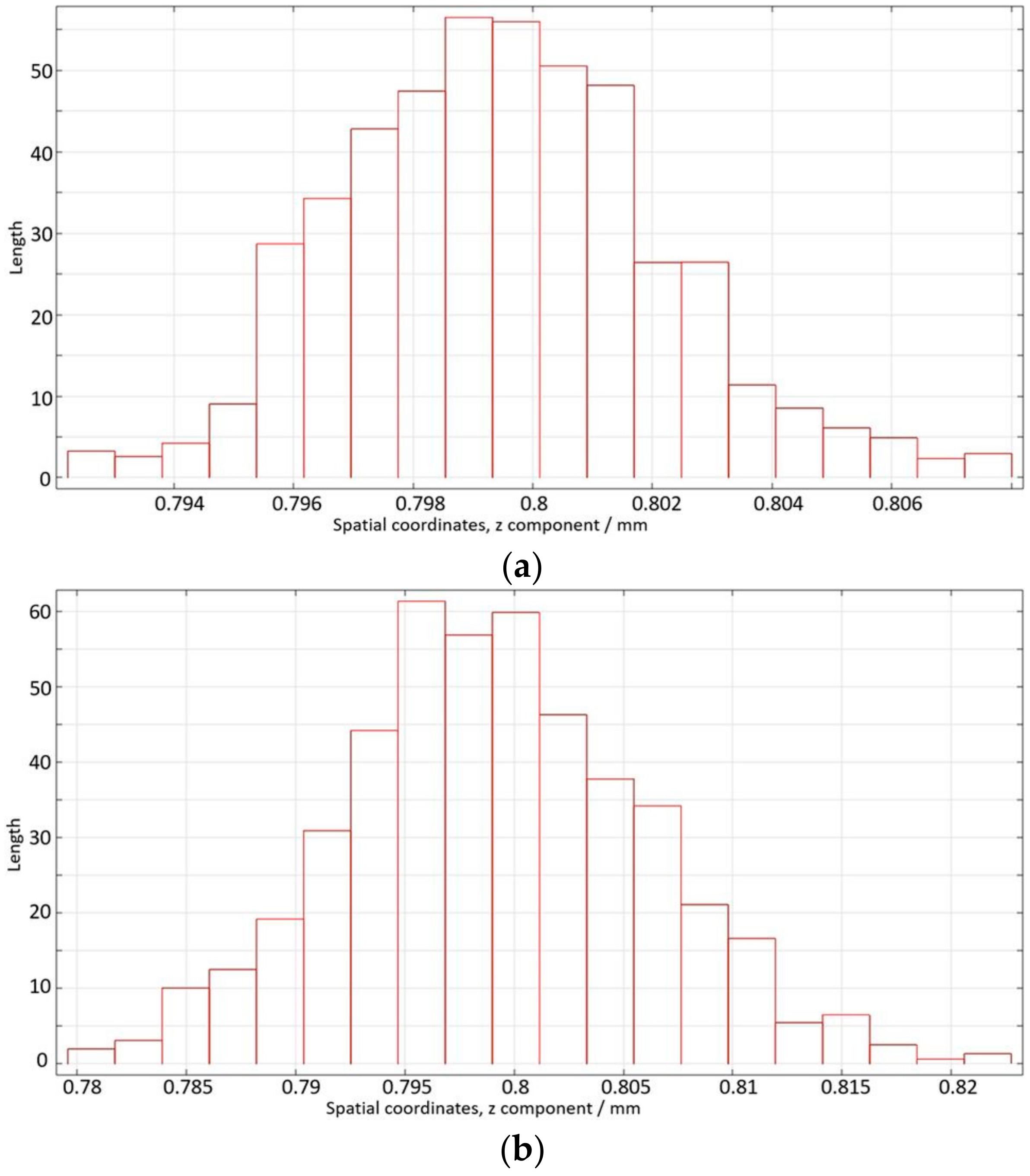
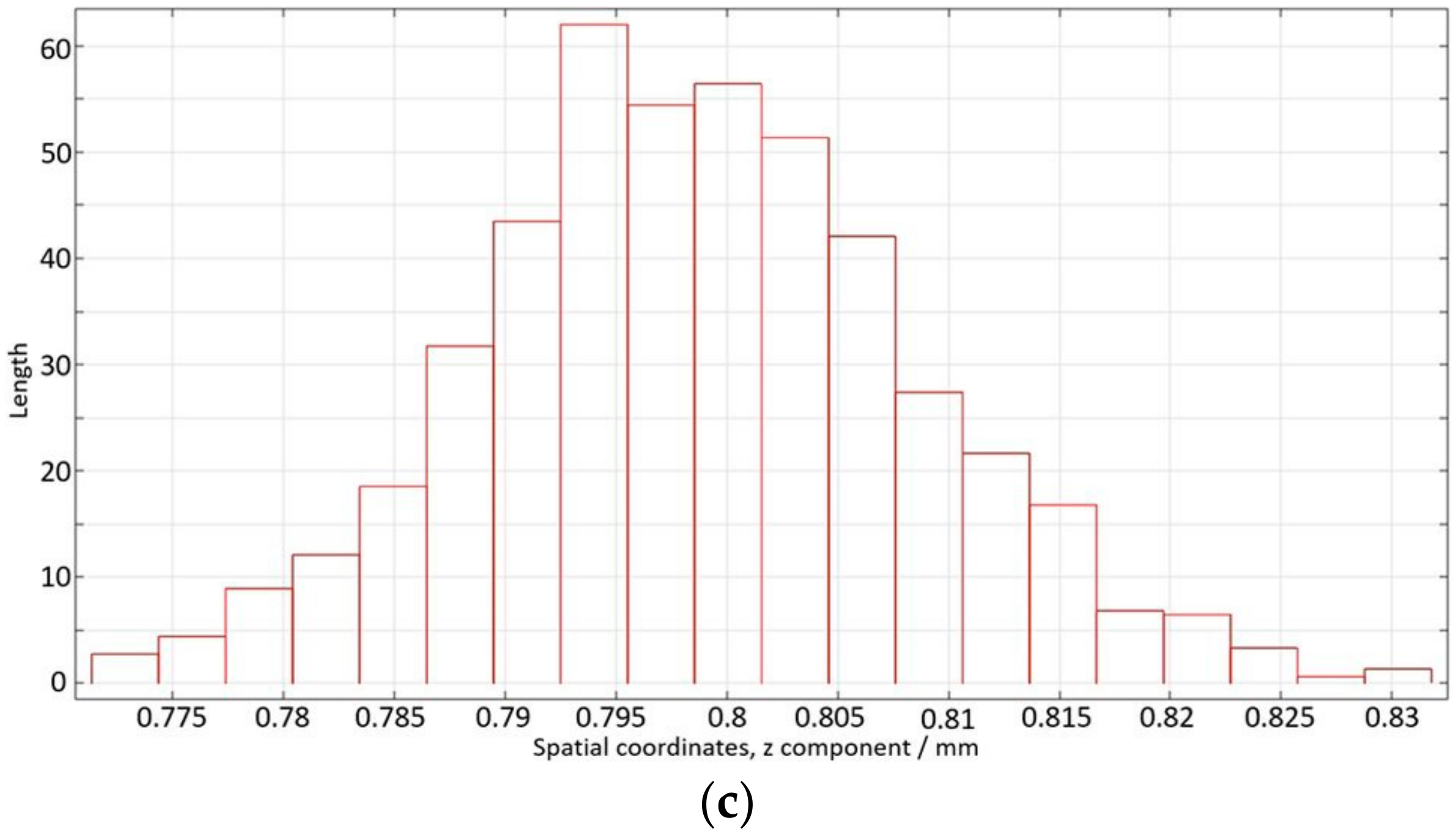
To implement those values, a parametric surface was generated at a certain height to avoid interference with the rest of the domains in the model. The population of samples generated was translated into peaks and valleys reflecting a natural variation in height. In the serpentine model, the integration of the GDL and membrane components increases the height of the model. Hence, the mean value of the normal distribution was set at 0.8 mm for the three different average roughness scenarios, reflecting the midpoint of the probability distribution function while representing the randomized parametric surface on the
z-axis as depicted in
Figure 2. Additionally, on the
y-axis of the histogram, the data points of the occurred coordinates or their interval were counted. On the other hand, the mean value of the normal distribution of the parallel model was set at 0.2 mm, as can be seen in
Figure A2.
2.3. Flow Analysis in Parallel and Serpentine GFCs
Combining both designs in a PEMFC can enhance its efficiency, with the anode side featuring a serpentine structure and the cathode side a parallel structure [
29]. The distinct flow directions in parallel and serpentine configurations affect fluid velocity, resulting in varying static and dynamic pressures. These pressure variations influence fluid diffusivity towards the microporous structures in the GDL and ionic mobility within the PEMFC [
53]. This strategy helps control excess water production from electro-osmosis and the anode BPP, thereby reducing droplet accumulation and slowing the formation of slugs in the cathode flow fields. This combination leverages the parallel flow field’s low-pressure drops compared to the high-pressure drops of the serpentine type [
54]. Hence, this topology can exploit the high-power output at the cathode and achieve a more uniform velocity distribution at the anode.
The validation of this comes from the two kinds of simulated GFC strategies, where the effects of the turbulent flow fluctuations are solved with the Reynolds-Averaged Navier–Stokes model. The pressure drop characteristics between the two kinds of GFCs are also verified from the simulated models as can be seen in
Figure 3, where the pressure difference between the inlet and outlet of both GFC types is obtained. The models examine the same channel geometrical characteristics with a height of 0.889 mm and a width of 2.07 mm, which possess an ideal flat surface.
The rationalization is to balance the trade-offs between the two approaches. Hence, in parallel GFCs, developing high-pressure drops at high current densities can be problematic as it causes insufficient gas supply and water removal. Therefore, the preservation of laminar flow is crucial when the parallel technique is implemented. When the serpentine one is selected, the flow should be preserved at as low levels as possible since the laminar flow is more easily controlled without high propagation of flow resistance. Reynolds number Re is the indicator of which kind of flow is dominating in GFCs and for the case of square-shaped ones, the equation is given below.
where
ρ is the density,
u velocity,
μ dynamic viscosity,
D hydraulic diameter,
Q flow rate,
A cross-sectional area of the flow channel,
P perimeter,
w width, and
h height. To ensure the preservation of laminar flow throughout the process simulation of both parallel and serpentine GFCs, an inequality should be true,
Re ≤ 2300.
Replacing the GFC cross-sectional area of 0.889 × 2.07 mm in Equation (6) and the maximum velocities of each case as derived from
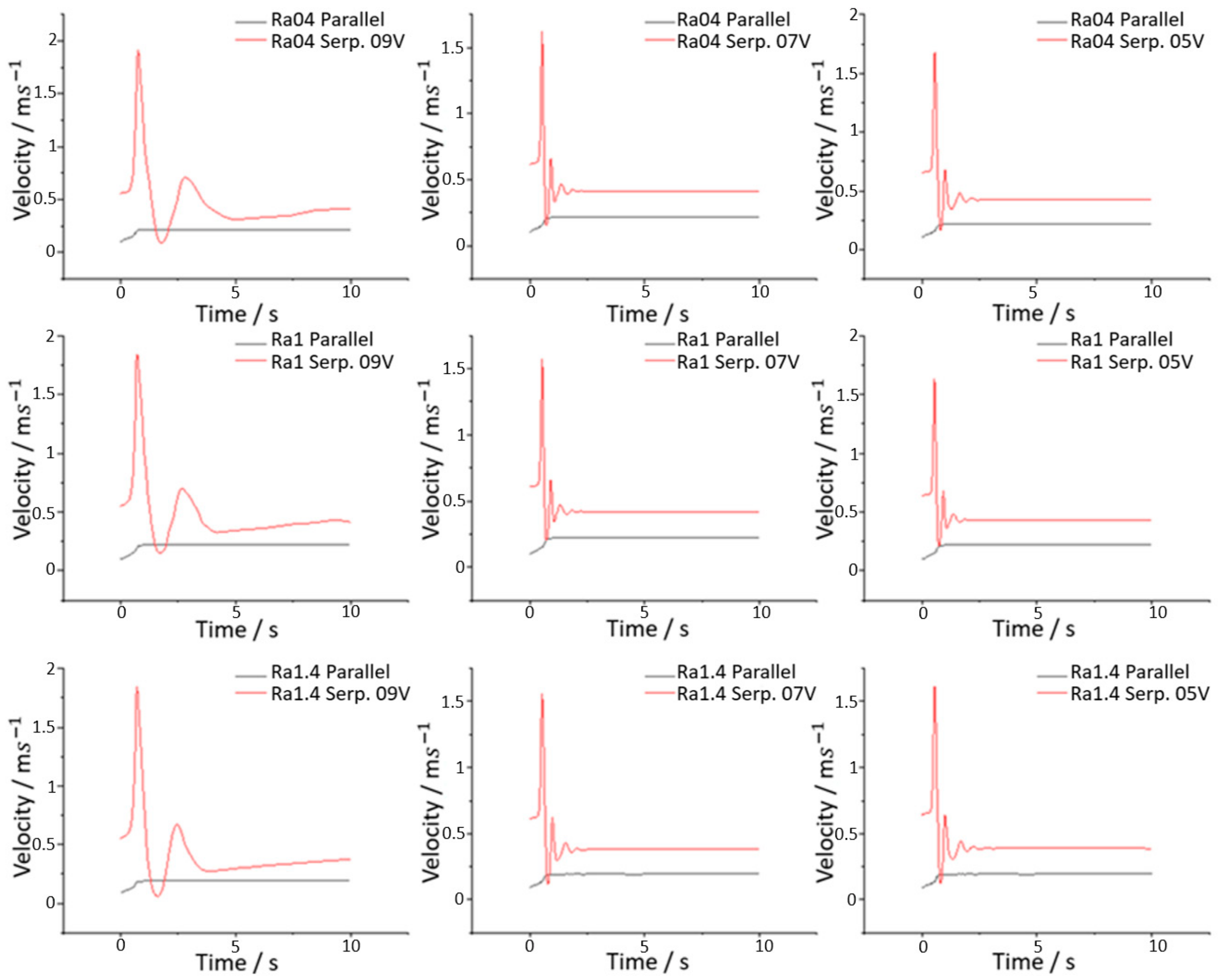
Figure 4. As depicted, the maximum mean velocity for the case of parallel GFCs, occurred at the outlet of the channel with 0.19 m/s, which obeys the rule of Reynolds number for the laminar flow regime. In the case of serpentine GFCs, the maximum mean velocity found is 2 m/s at the outlet of the channel when operating at 0.9 V and the flow runs at the transition range since
Re ≈ 3400 > 2300. The other two scenarios for rated PEMFC at 0.7 V and 0.5 V keep the flow above the laminar level with
Re ≈ 2800 and
Re ≈ 2900, respectively.
The height of the channel in both flow channel strategies signifies that the introduction of roughness is only a variation of a few parts per thousand, which is too low to influence the speed of the fluid as the channel length remains the same. The Reynolds number indicates that the order of magnitude of the roughness values used in this study provides insufficient friction to disrupt the flow regime throughout the flow field. This is demonstrated in
Figure 5, where the data from the channels’ mean velocities at the outlet side are gathered. The Reynolds number remained well below 2300 according to the inertia and the viscous forces applied for all three different values of surface roughness for the parallel PEMFC model. The maximum mean velocity from 0.19 m/s when no roughness is applied was boosted to 0.22 m/s when roughness of 1 µm was incorporated. Similarly, the Reynolds number for the serpentine structure stayed above the laminar barrier as it was for the flat channels but with decreased maximum velocity for all the selected roughness values. This slower movement of the gas in the rough serpentine flow channels reduced the Reynolds number by 200 or 300, which can be critical for avoiding the uneven distribution of reactants and current density. Lastly, when the simulation time approached the end, the mean velocity in the case of roughness 1 µm was less affected, remaining close to the ideal case of flat channels.
2.4. PEMFC Models
As discussed in
Section 1, the most popular structures of BPPs are the parallel and serpentine designs. Regardless of the GFC design, the number of channels employed in the industry production ranges from more than 20 [
29] to about 250 [
36]. In both parallel and serpentine designs, a simpler geometry is adopted with respect to the number of gas flow channels simulated to extract the final data, as well as the length of the PEMFC device. This modification does not affect the flow regime and the Reynolds number as analyzed in the previous subsection, so the results of the study remain valid. The impact of surface roughness can therefore be expressed by the simulations’ output regardless of the actual number of channels in the fuel cell device.
Crossmatching literature data regarding the most suited dimensions of GFCs’ showed that studies have been conducted with various aspect ratios (width/height) adopted either for numerical studies or the manufacturing of physical components. Some of the instances employed in parallel and serpentine structures contain aspect ratios of 0.4/1 mm both included for simulation experiments [
31,
36], others of 0.75/1.5 mm [
30], and 0.3/1.5 mm [
55] for numerical investigations as well. The last aspect ratios utilized in the literature are 1/1 mm and 0.9/0.9 mm, established in theoretical and practical models, respectively [
35,
55]. Therefore, as mentioned above, the equal width dimension to height has been proven feasible as a strategy for channel geometries. In addition, the surface roughness effect is more significant as the channel is no longer that coarse to enable better flow which is still at the transition or turbulent region. The PEMFC model used for analysis in the next section is depicted in
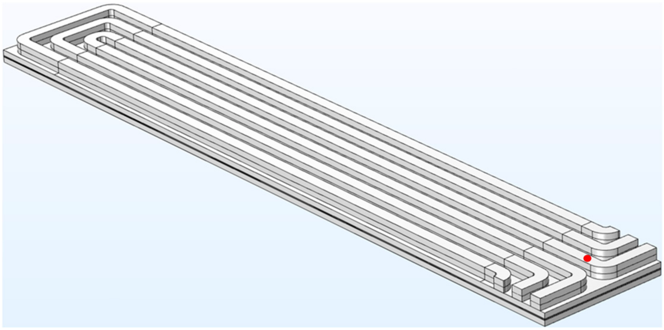
Figure 6 and its channel dimensions are formed with a 0.8/0.8 mm aspect ratio.
The model consists of a flow field in a serpentine configuration, a membrane, the cathode, and anode GDL components except for the anode flow field domain located at the bottom of the component as visualized in
Figure 6. The inlet is assigned on the left side and the outlet to the right side respectively. The number of serpentine channels used is three in order to reduce computational weight and time. For the sake of simplicity, the incorporation of the anode flow fields is avoided. Hence, the cathode current collector is selected to have applied the electric potential and the selected counterpart on the anode domain is grounded, as it can be influenced by the physics dynamics of the anode flow field.
The geometrical characteristics of the cell were set by COMSOL Multiphysics in the model, which can be accessed from the application library [
56]. To minimize the unit ratio between the parametric surface geometry and the fuel cell geometry, a modification of the device characteristics had to be implemented. The main adjustment in the geometry is in the units, as from the meters scale it shifted to millimeters. This conversion has an impact on the units of the measurable quantities. The physics parameters in the simulated models were selected to establish the gas flow fundamental characteristics in a continuous phase. Finally, the solver was set to compute the fluid dynamics and gas reaction on the cathode side concerning the evolution of gas pressure and velocity in a time-dependent simulation coupled with the different electrode potentials.
3. Simulation Results
The model presented above is constructed in a manner such that the parametric surface plane should cover the domain area of the flow field geometry of the BPP excluding the inlet and outlet. Then, by using the partition domains and delete entities operations, the roughness becomes part of the inner texture of the flow channels. To address this multiphysics problem, two parameters were initialized in both models, the reference base pressure level of 1 atm and the reference base temperature of 293.15 K. Prior to the analysis of the simulation outputs of the model, it is important to note that the temperature does not remain constant in a fuel cell and potentially along the flow channels due to continuous electrochemical reactions. For this reason, the computation of the physical quantities as pressure and velocity becomes particularly difficult. Those quantities are evaluated as a function of time, in milliseconds, and the output voltage until their entrance to a steady state. The model simulation examines the fuel cell under three occasions of operating voltages: 0.5 V, 0.7 V, and 0.9 V.
The operating voltage of a PEMFC is directly governed by the electrochemical reaction taking place at the electrodes. However, in this case, the potential difference between the anode and cathode is kept constant. Hence, the mass transport, reaction rate, and pressure drop significantly affect the current density. The results attained from the selected average surface roughness rates are also compared with the model outputs where no surface roughness is applied. The comparison was performed by tracking the respective physical quantities in the three-dimensional space developed in the gas flow channels during the process. To be confident regarding the acquired data sets, a point probe domain was generated for each model, which acted as a sensor to evaluate the extracted physical quantities. The probe point was created by the setting of triplet coordinates (
x,
y,
z), which were selected for their proximity to the outlet side where the impact of the surface roughness is more expository as the gas takes a longer time traveling to the GFC, as presented in
Figure 3,
Figure 4 and
Figure 5. The fuel traveling through the channel may undergo a phase transition due to high-pressure gaps between the inlet and outlet [
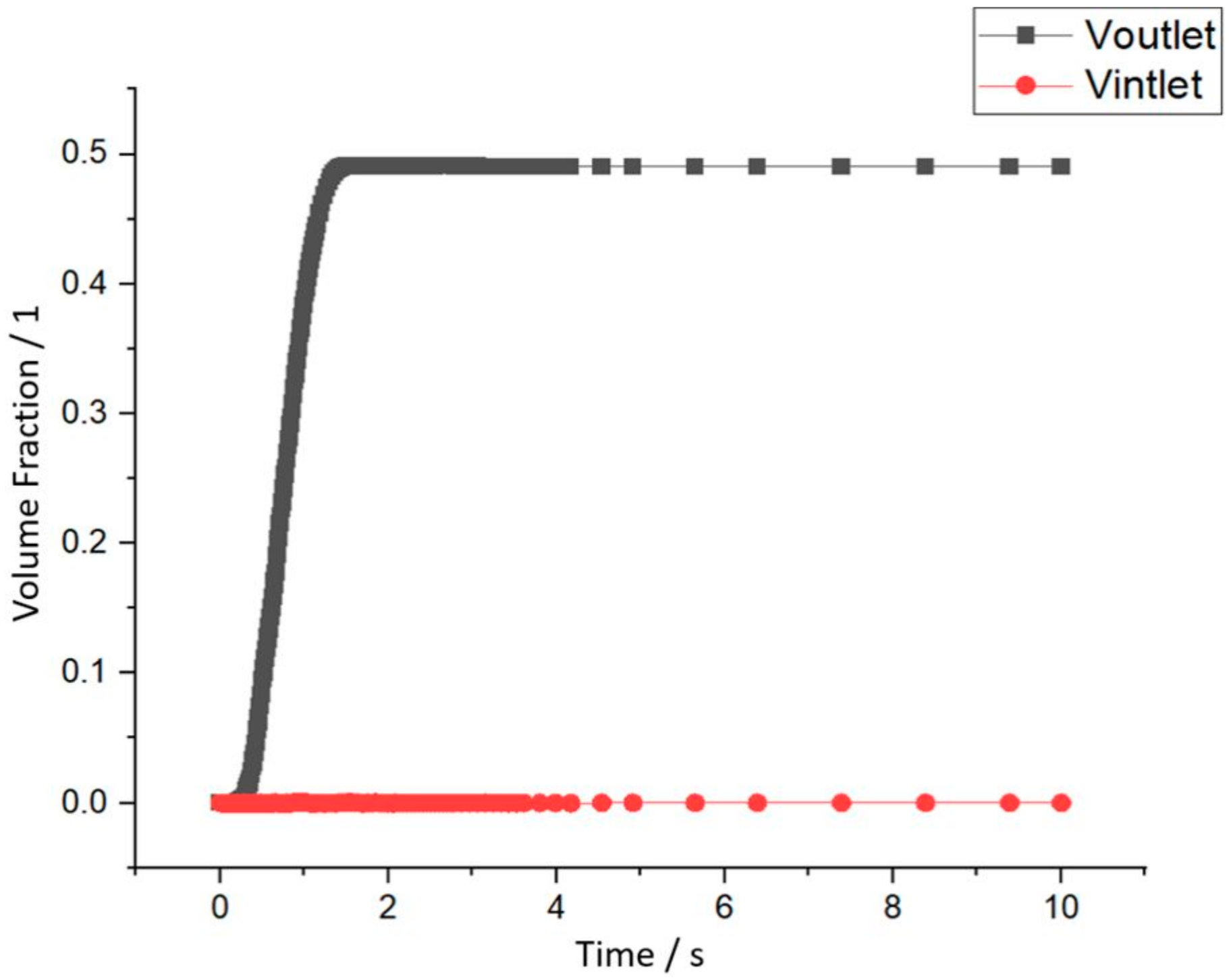
55]. This means that the flow rate at the outlet of the flow channel is different than in the inlet and the volume fraction is therefore increased as the reaction is initiated. A correlation between the volume fraction at the inlet and outlet of the parallel structure is visible in
Figure A3.
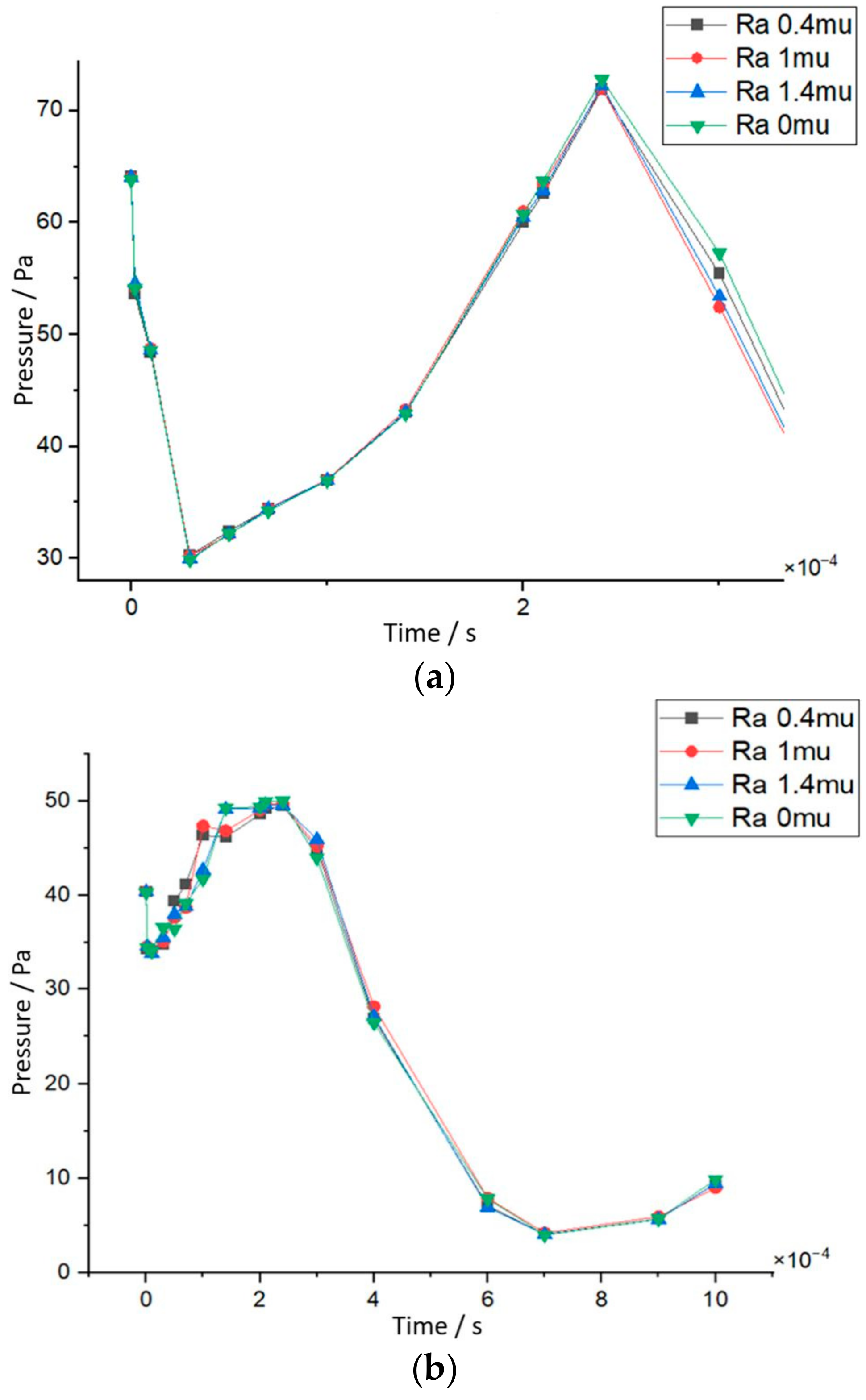
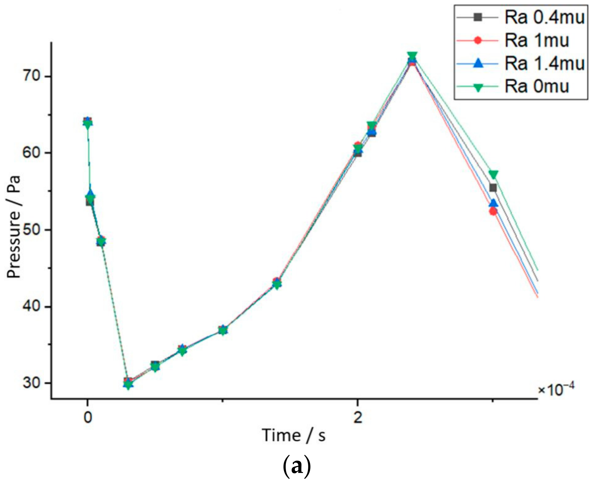
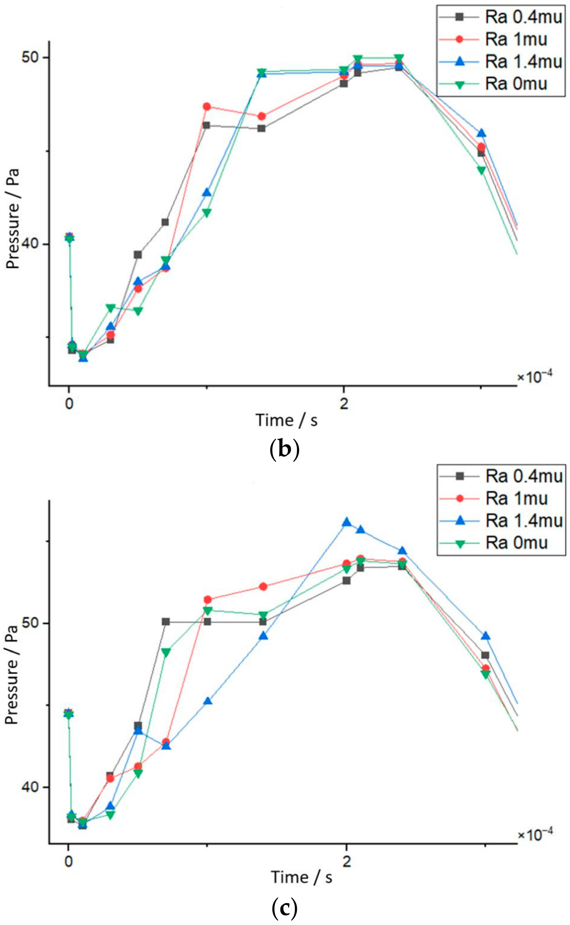
The simulation revealed a steep pressure decline in the first tenths of microseconds, as can be seen in
Figure 7, which verifies the inversely proportional relationship with the volume fraction. The mean velocity of the gas can determine the quality of the electrochemical reaction as it controls the rate of mass transport of the reactants to the electrode surface. The pressure difference between the inlet of the channels and the outlet that drives the gas flow can in turn affect the velocity of the reactant gas. In the simulated cases, at T0 the gas production is initiated at the inlet side of the cathode channels. The changes in the physical quantities are then mapped and analyzed mainly for the first couple of milliseconds. More specifically, the first pressure reading in the case of 0.9 V electrode potential (
Figure 7a) is higher than the other two cases (
Figure 7b,c), presumably due to the fact that more fuel is required. This signifies that a higher mole of reactant gas is concentrated on the outlet at the cathode side as the electrode potential increases.
The pressure followed a downward trend before it ascended until reaching a maximum peak at around 2 ms for each case of the tested electrode voltages. For the case wherein the electrode voltage was set at 0.9 V, more time was required to reach the maximum pressure point, as visible in
Figure 7 and
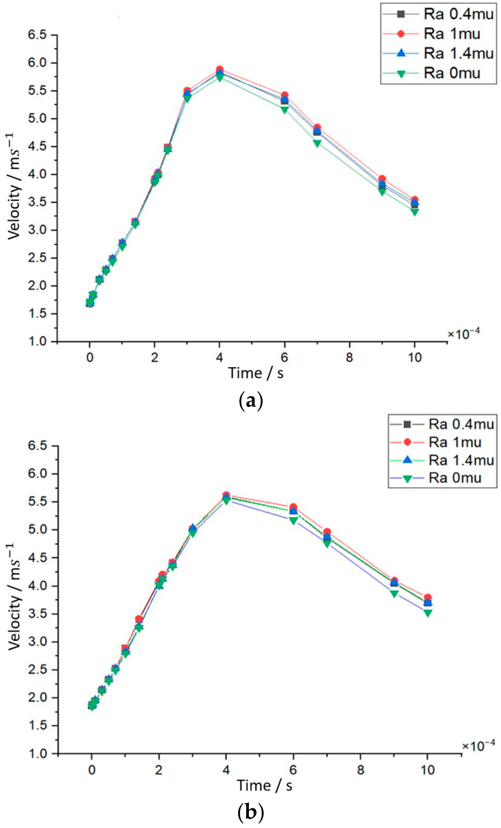
Table A1. In this case, the highest pressure was achieved, which coincided with the velocity data, considering that it accomplished a maximum value the fastest, as presented in
Figure 8 and
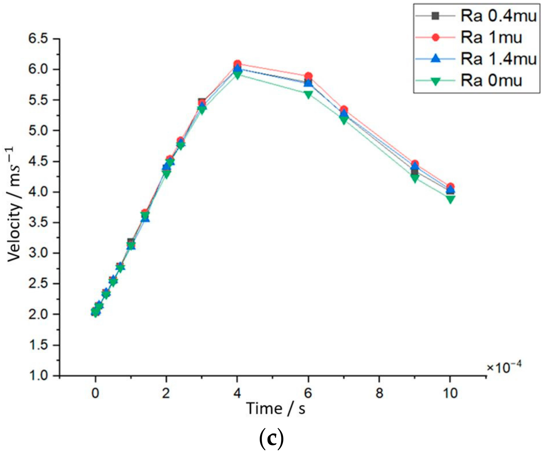
Table A2. As observed by the simulations, the high-pressure drop between the inlet and the outlet of the flow channels influenced the peak pressure; likewise, the latter proportionally affected the mean gas velocity. It is worth mentioning that the lowest velocity values were noticed for the case of 0.7 V operating voltage, where the values of maximum pressure were also the smallest. As specified by the simulated data, the second highest pressure at end time was found in the first case of 0.5 V where the highest velocity values were reached, as can be seen in
Figure 8c.
Maintaining the appropriate pressure and velocity levels of the reactant gases combined with a shorter time span where the pressure is entering a steady state ensures efficient operation of the fuel cell at the rated operating voltage. The recommended operating voltage should be 0.7 V because the pressure at the anode side achieved the fastest the lowest peak and the velocity exhibited a similar trend, as depicted in
Table A1 and
Table A2. This balances the tradeoff between pressure and velocity while verifying their proportional relationship with a time delay of approximately 2 ms.
After identifying the general pattern of pressure, velocity, and their interrelation as a function of voltage and time, the impact of the surface roughness parameter was analyzed. Regardless of the electrode potential, when roughness was zero, the pressure drop fell to the lowest level, as depicted in
Figure A4 and
Figure A6, and it stabilized faster than the other scenarios at a specific time as the simulation propagated to the end. However, during its peak pressure time and when it stabilized, noted as T10 in
Table A1, the flat channels retained the highest pressure compared to the cases with roughness, except for the peak pressure at 0.5 V, which was a result of an applied surface roughness of 1.4 µm, as illustrated in
Figure 7c. Nevertheless, the reaction occurring at the electrodes was directly coupled to high or low pressure and velocity. There is a tradeoff relationship, as high pressure and velocity can be harmful to the lifetime of a PEMFC. For example, in GFCs with ideal flat surfaces, the pressure is preserved at the highest levels, but the velocity is on the contrary at the lowest levels, as visible in
Figure 8 and
Figure A5. This is costly and inefficient when it comes to the safe and healthy long-term operation of such devices.
These data indicate that surface roughness in GFCs can optimize the performance of fuel cells. Apart from the case with no roughness, most of the lower pressure readings were generated by the GFC model with 0.4 µm roughness, as can be seen in
Figure A4 and
Figure A6. Especially for 0.5 V and 0.7 V, it started with the second highest one, continuing with the lowest to the peak and end of time. For the case of 0.9 V, it began with the highest pressure but with the same result. This high pressure at T0, the outcome of the high-pressure drops between the inlet and outlet, led to the second-highest velocity at
Tpeak but ranked third at the end. On the other hand, most of the high-pressure readings were produced by the case of 1.4 µm. More specifically, for 0.5 V and 0.7 V, it started with the third-highest pressure and continued with very high values to the peak and toward the end. The production of high-pressure drops has an impact on velocity, as revealed by a time delay between the two quantities in the simulations. The intent is to finish with the second-highest velocities in all the ranges of operating voltage, as demonstrated in
Figure 8 and
Table A2.
By combining insights from
Figure 8 and
Figure A6, it is evident that the trade-off relationship between pressure and velocity adheres to Equation (2). This is particularly noticeable in the case of 0.9 V, where a significant pressure drop was observed, indicating a slower flow within the first two seconds. This drop is linked to the mole fraction of the reactant, as higher operating voltages require more fuel. With this high electrochemical activity, the system requires more time to build up sufficient pressure due to the rapid consumption of gases.
It is important to note that the pressure gradient curves reflect the geometry of the channels, which can include fluctuations, spikes, and plateaus [
57]. Thus, surface roughness becomes crucial at high voltage requirements, as it helps maintain a high average pressure gradient by preserving optimal low values. The noisy pressure drop values may contribute to more variable cell potential and current density curves, as the timing of the pressure curves in
Figure 7 aligns with the 0.2 ms peak time observed in experimental data on a PEMFC [
58].
Furthermore, the gas velocity produced by the GFCs that adopted a surface roughness of 1 µm developed a maximum performance for every operating voltage, as shown in
Figure 8 and
Figure A5. This is due to the pressure curve maintaining a higher-pressure gradient, efficiently boosting fuel velocity to its maximum. Notably, a surface roughness of 1 µm achieved maximum velocity for 0.5 V, 0.7 V, and 0.9 V without recording the highest-pressure gradients among the cases. Furthermore, it resulted in the third-lowest pressure at the anode side during subsequent steps, indicating efficient fuel conservation. This suggests an optimal surface roughness that enhances electrochemical conversion quality.
4. Conclusions
The simulation results showed that rough surfaces on the GFCs of manufactured BPPs do affect the supply of reactants and the removal of the by-product water. On the cathode side, a parallel structure was adopted, and roughness showed that it enhanced the speed of the fluid or reactant gas while remaining with the laminar flow barrier according to the Reynolds number. On the anode side where the serpentine channels were implemented, the gas did not change the flow regime, keeping the Reynold number above the laminar values. However, disregarding the roughness or the geometrical characteristics of the GFCs, the most economical strategy for efficient operating voltage was 0.7 V as the pressure drop was lower, affecting the mean velocity and in turn the Reynolds number.
Comparatively, smoother surfaces resulted in lower pressure differentials but at the cost of reduced reactant velocity, while rougher surfaces exacerbated pressure drops. Beyond this observation, it was noticed that there was an optimal range of applied surface roughness on GFCs, 0.4 μm ≪ Ropt ≤ 1 μm, which improved the overall performance of a single PEMFC, providing enhanced electrochemical conversion efficiency and operational stability. This phenomenon became apparent for both parallel and serpentine models even with different aspect ratios. More specifically, when Ra = 1 μm, the gas or fluid speed was higher at Tmax and T10 for both parallel and serpentine techniques. The source of this pattern is the minimized pressure drop from the inlet to the outlet of the 1 μm rough channel, which makes the mass transport smoother.
Since surface roughness is a natural product of machining processes, tuning the roughness of a BPP should be possible during fabrication. In commercial applications, multiple cells are typically stacked together to provide sufficient power. Cell units are connected in series where as many as 500 single PEMFC cells are combined in a module to achieve a power output on the order of 100 kWatt [
59]. Therefore, the small differences in performance, as presented in
Section 3, can be significant when numerous PEMFC stacks are combined in series. The results of this study suggest that the verification process should be implemented during PEMFC fabrication where prototypes are inspected to ensure the desired surface roughness is attained and tested under a range of load conditions. In this context, the adoption of an optimum surface roughness can ameliorate the mass transfer transport, water management, and current distribution.
By delving into the micro-scale aspects of flow channel design, this study aimed to fill a critical gap in the existing body of knowledge, providing a foundation for future advancements in fuel cell technology. This research lays the groundwork for future development of more reliable and efficient fuel cells capable of meeting the increasing demand for sustainable energy solutions.


