Abstract
This paper develops a model for lithium-ion batteries under dynamic stress testing (DST) and federal urban driving schedule (FUDS) conditions that incorporates associated hysteresis characteristics of 18650-format lithium iron-phosphate batteries. Additionally, it introduces the adaptive sliding mode observer algorithm (ASMO) to achieve robust and swiftly accurate estimation of the state of charge (SOC) of lithium-iron-phosphate batteries during electric vehicle duty cycles. The established simplified hysteresis model in this paper significantly enhances the fitting accuracy during charging and discharging processes, compensating for voltage deviations induced by hysteresis characteristics. The SOC estimation, even in the face of model parameter changes under complex working conditions during electric vehicle duty cycles, maintains high robustness by capitalizing on the easy convergence and parameter insensitivity of ASMO. Lastly, experiments conducted under different temperatures and FUDS and DST conditions validate that the SOC estimation of lithium-iron-phosphate batteries, based on the adaptive sliding-mode observer and the simplified hysteresis model, exhibits enhanced robustness and faster convergence under complex working conditions and temperature variations during electric vehicle duty cycles.
1. Introduction
In recent years, the pressing global issues of the energy crisis and environmental pollution have demanded urgent solutions. To address these challenges, the widespread development of electric vehicles has become a crucial objective for nations worldwide. The promotion and adoption of electric vehicles carry the potential to positively impact and, in some cases, resolve energy crises and environmental pollution problems [1,2]. Lithium-ion batteries serve as a widely employed energy storage source, offering a versatile solution to meet the global energy demands of electric vehicles and various applications. Li-ion batteries exhibit numerous advantages as a power source across a diverse array of devices [3,4,5,6], including excellent high energy density, the absence of memory effect, and low self-discharge rate. The advantageous energy characteristics, coupled with substantial cost reduction, have positioned Li-ion batteries as an indispensable component in the energy sector. This is particularly evident in critical areas like electric vehicles.
The state of charge is a critical indicator that reflects the available state of the remaining charge. Monitoring SOC is imperative to regulate the extent of charging and discharging, preventing both overcharging and overdischarging [7,8,9,10]. SOC is a non-directly measured physical quantity that can only be obtained through indirect methods. Presently, SOC estimation methods primarily fall into three categories: the Ah integration method, data-driven estimation methods relying on data, and model-based estimation methods [11]. The Ah integration method’s inadequate initial value results in error accumulation [12]. The data-driven method relies solely on the mapping relationship between system inputs and outputs to construct a state-of-charge estimation model. However, a notable drawback is its requirement for a substantial number of battery data samples for learning, which is challenging to obtain. Moreover, the selection of battery data samples significantly influences its estimation accuracy, posing challenges in its application to battery management systems (BMS) with constrained computational capabilities [13]. Currently, model-based methods are widely used for state-of-charge estimation [14]. This approach is initiated by establishing the electrochemical model or equivalent circuit model (ECM) of the battery. The electrochemical model exhibits high estimation accuracy [15,16]. ECM simulates the battery’s internal reactions by constructing a nonlinear dynamic relationship between the open circuit voltage (OCV), load current, and terminal voltage. The method then establishes state-space equations and employs a filter or observer approach to estimate the state of charge values within the model. References [17,18] achieved favorable estimation results through the establishment of a Thevenin equivalent circuit model and the application of the Extended Kalman Filter (EKF) for state-of-charge estimation. References [19,20] established a Thevenin equivalent circuit model and introduced an enhanced Unscented Kalman Filter (UKF) to achieve improved estimation performance and higher accuracy in state-of-charge estimation. Cui et al. [19] employed the Cubature Kalman Filter (CKF) based on Thevenin’s model for state-of-charge estimation, ensuring the non-negativity of the covariance matrix and preventing filter divergence. Various filter algorithms like EKF, UKF, and CKF were employed in the aforementioned studies, each with some algorithmic enhancements. However, Kalman filters exhibit limitations in certain aspects [21,22,23,24,25], particularly their sensitivity to inaccurate initial conditions and unknown perturbations, resulting in substantial estimation errors in the model.
The observer-based estimation method can address the limitations of the aforementioned filter-based state-of-charge estimation methods. Sun Dong et al. [26] initially established a first-order RC equivalent circuit model and employed offline parameter identification and observer design for estimation. The method exhibits excellent robustness, effectively handling uncertainties and perturbations in the system. However, the method experiences output jitter during the application, potentially introducing disturbance to the estimation results. Sui Xin et al. [27] developed a first-order RC equivalent circuit model and introduced an enhanced Sliding Mode Observer (SMO) for estimation. The method utilizes a sigmoid function in place of the traditional sign function and incorporates online updating of the parameters of the observer model. With these enhancements, the method can mitigate model errors, address the output jitter problem, and exhibit strong robustness. Nath et al. [28] established a second-order RC equivalent circuit model and introduced an ellipsoid-based improved sliding film observer. This observer is capable of achieving higher accuracy in state-of-charge estimation even in the presence of boundary uncertainties and external disturbances. Additionally, the method introduces an additional adjustable variable µ to enhance the convergence speed of the estimated state of charge, although its precise definition is not strictly provided. References [29,30,31,32] employed SMO algorithms based on a constant gain, while references [33,34] utilized SMO algorithms incorporating adaptive (time-varying) switching gain. The results suggest that SMO based on adaptive (time-varying) switching gain outperforms SMO based on constant gain [35,36,37]. The sliding mode observer is a type of state observer known for its ease of convergence, parameter insensitivity, and lower computational intensity. It can consider the convergence speed, robustness, and computational complexity in lithium-ion battery state-of-charge estimation. Due to its strong anti-jamming capability, it exhibits excellent robustness when applied to estimation, maintaining a high level of robustness even amid dynamic changes in model parameters under complex operating conditions during electric vehicle duty cycles.
Previous studies initially constructed either a first-order or second-order equivalent circuit model and subsequently estimated the SOC through the mapping relationship between open circuit voltage (OCV) and SOC using Kalman filter or sliding mode observer methodologies, yielding certain outcomes. However, these studies primarily concentrate on the deficiencies in the construction of the filter or observer itself, overlooking the impact of battery hysteresis characteristics on battery performance parameters. Due to the characteristics of battery materials, the relationship between OCV and SOC does not exhibit a strictly one-to-one mapping. Wehbe et al. [38] discovered that the accuracy of the equivalent circuit model is constrained by hysteresis properties. Kwak et al. [39] incorporated hysteresis characteristics into a first-order Thevenin equivalent circuit model and utilized the least squares method for model parameter identification. Experimental tests demonstrated that this method is more efficient compared to the estimation approach using EKF. Tran et al. [40] incorporated the hysteresis feature into a first-order RC model and applied it under both dynamic and non-dynamic conditions. The results demonstrate that considering the hysteresis feature can enhance the estimation accuracy of the terminal voltage in the first-order RC model.
Based on the above study, this paper proposes an innovative method for SOC estimation of lithium-iron-phosphate batteries based on a sliding mode observer with a simplified hysteresis model during electric vehicle duty cycles:
- Both the hysteresis characteristics and the influence of temperature on the hysteresis effect are taken into consideration, leading to the implementation of mechanistic analysis and battery model modeling.
- The sliding mode observer exhibits high robustness, and the identified parameters used for SOC estimation at different temperatures remain highly robust while maintaining high accuracy over an extended time window in on-board conditions.
- The proposed method reduces the jitter problem associated with the conventional sliding mode observer, resulting in reduced computational complexity and faster convergence speed.
2. A Study of SOC Estimation Methods
2.1. Simplified Hysteresis Modeling
When the battery undergoes continuous charging from 0% SOC to 100% SOC and then continuous discharge from 100% SOC to 0% SOC, it creates an open-circuit voltage interval, representing the region between the OCV curves of continuous charging and discharging [41]. Subsequently, there is a hysteresis loop in the relationship curve between SOC and OCV during incomplete charge/discharge cycling due to the hysteresis characteristic influencing the battery voltage. At the same SOC, the battery open-circuit voltage differs for different charging and discharging paths, with the charging open-circuit voltage usually higher than the discharging open-circuit voltage. Therefore, these characteristics must be considered when mapping SOC from OCV. As illustrated in Figure 1, the discharged part of the figure reveals the high sensitivity of SOC to open-circuit voltage, where a slight voltage deviation induces a significant SOC change. Under the same open-circuit voltage, the corresponding SOC can differ significantly, emphasizing that the impact of hysteresis characteristics cannot be overlooked.
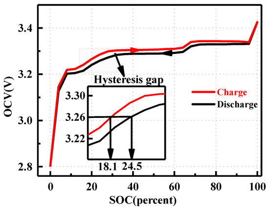
Figure 1.
Hysteresis characteristic.
The Thevenin model serves as a battery model with the advantages of low computational effort, easy parameter identification, and high accuracy, capturing the relaxation effect of the battery [42]. This model is utilized to simulate the dynamic characteristics of the battery using the RC module. Previous research has demonstrated that increasing the order of the RC network enhances the theoretical accuracy of battery estimation. However, escalating the order of the RC network introduces complexity to the system structure and poses challenges for identification and state-of-charge estimation algorithms. Recognizing that the error in relaxation effect modeling can be compensated by a robust sliding mode observer and that real-time estimation demands simplified computation, implementing a second-order circuit model for real-time observation of the battery state in EVs proves challenging. Therefore, considering the trade-off between the simplicity of the power battery model structure and model accuracy, this thesis opts for the practical first-order RC equivalent circuit model. Due to the presence of hysteresis effects, a direct one-to-one correspondence between SOC and OCV is not observed. Even after eliminating the effects of relaxation (polarization and ohmic internal resistance), the charge/discharge curves of the same battery do not precisely overlap. Simple first- or second-order equivalent circuits fail to capture this behavior of the battery. Therefore, to describe the hysteresis phenomenon where the charge–discharge OCV–SOC curves do not coincide, this paper proposes a simplified hysteresis model. Figure 2 illustrates this model, which consists of two OCV–SOC open-circuit voltage sources—one for charging and another for discharging. The selection of these sources is determined by the current flow through two ideal diodes [43].
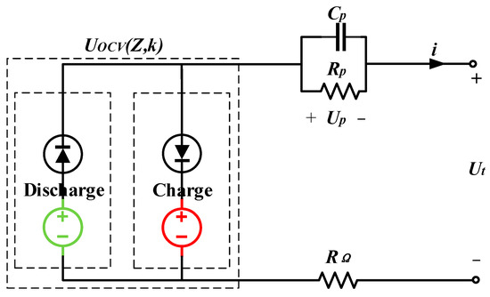
Figure 2.
Simplified equivalent circuit model.
The hysteresis characteristics of the battery are captured by two distinct OCV–SOC curves, one for the charging process and another for the discharging process. The relaxation model is depicted in the right half of Figure 2, where is the ohmic internal resistance, is the polarization internal resistance, is the polarization capacitance, is the polarization voltage of the battery, and is the terminal voltage. Based on the Kirchhoff equation, the circuit illustrated in Figure 2 can be expressed by Equation (1).
To characterize the hysteresis phenomenon where the charging and discharging OCV–SOC curves do not overlap, this paper proposes a simplified hysteresis model. The model comprises two OCV–SOC open-circuit voltage sources, one for charging and one for discharging, which are determined by the current flow direction of two ideal diodes. The mathematical expression of the model is presented in Equation (2).
Here, denotes a function of SOC of the battery, represents the state of charge, and is defined as a selection factor that chooses the discharging process when = 1 and the charging process when = 0.
2.2. Effect of Temperature on Hysteresis Modeling
To investigate the hysteresis characteristics of lithium-iron-phosphate batteries under varying ambient temperatures, this study selects lithium iron phosphate batteries with a capacity of 1.6 Ah as the experimental subject. The experiment is conducted at temperatures of 0 °C, 25 °C, and 45 °C. A full interval charging and discharging cycle is chosen as the experimental interval, and the optimized incremental test method is employed for the open-circuit voltage test. After each 4% SOC step increase or decrease, the battery is allowed to stabilize for 3 h to ensure voltage stability. The OCV–SOC charge–discharge curves are then obtained for different temperatures, and the hysteresis gap voltage, which represents the difference between the charge curve and the discharge curve, is calculated. These results are presented in Figure 3 and Figure 4.
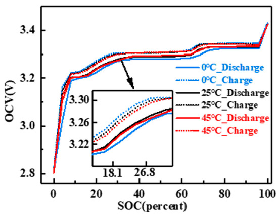
Figure 3.
Hysteresis curves at different temperatures.
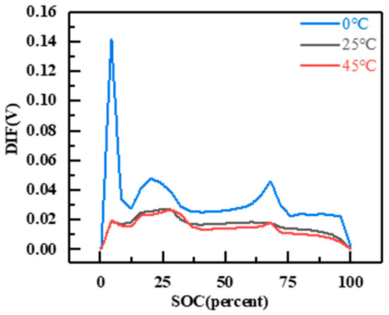
Figure 4.
Hysteresis gap voltage at different temperatures.
The hysteresis curve is influenced by temperature, as observed in the figure. At an operating temperature of 0 °C, the hysteresis voltage reaches its maximum value. The primary peak has a peak value of approximately 0.14 V, and the secondary peak has a peak value of around 0.05 V. These values increase by approximately 0.12 V and 0.03 V, respectively, compared to the values at 25 °C. However, when the temperature is increased to 45 °C, the change in hysteresis voltage is not significant. The positions and sizes of the primary and secondary peaks are almost identical to those at 25 °C, but they are better preserved during the plateau period compared to the low temperature. However, irregular jitter starts to appear near 13% of SOC. Overall, the hysteresis gap voltage difference at high temperatures is slightly lower than at 25 °C. For Li-FePO4 batteries, their hysteresis characteristics are not sensitive to high temperatures, as a 25 °C temperature increase is insufficient to cause significant hysteresis changes. In contrast, the effect of low temperature on hysteresis performance is more substantial. A 25 °C temperature difference at low temperatures significantly increases the hysteresis voltage. This can be attributed to the lower activity of lithium ions at low temperatures, resulting in a greater delay in the process of positive and negative electrode de-embedding and weakening the positive electrode’s ability to be re-embedded. Additionally, the limitations of the materials used in lithium iron phosphate batteries contribute to their poorer performance at low temperatures. In the low-temperature cycle, the open circuit voltage of the discharge curve is lower, leading to an increase in hysteresis voltage [44].
Through the analysis conducted in this paper, the relationship between OCV of the battery and the SOC is established using Equation (3). However, this equation does not account for the influence of temperature on the battery’s OCV. To address this limitation, the polynomial fitting parameters and are adjusted to incorporate the temperature variable , as shown in Equation (4). This modification allows for a more precise characterization of the relationship between battery OCV and SOC at different temperatures.
The electrical behavior model of lithium-iron-phosphate batteries, incorporating the hysteresis effect and relaxation effect, has been established thus far. The subsequent step involves parameter identification for the correlation coefficients within the established battery model.
2.3. Model Parameter Identification
To accurately characterize the relaxation characteristics of the battery at different temperatures, it is necessary to identify the parameters of the battery’s internal resistance, polarization resistance, and polarization capacitance within the model. This parameter identification process involves mathematically fitting the resting phase of each pulse during offline parameter acquisition. During the final charging phase, once the voltage response reaches its peak value, the current instantaneously drops to 0. Simultaneously, the voltage decreases from its peak value to a specific point, which represents a voltage drop across the ohmic internal resistance. Following the resting phase, when the current reaches 0, the voltage gradually decreases towards the open circuit voltage value. During this phase, the voltage remains constant, indicating the zero-input response of the RC link within the equivalent circuit model. The same process applies to the discharge phase.
The internal parameters of the battery, such as the battery internal resistance, polarization internal resistance, and polarization capacitance, exhibit variations with temperature. To accurately model the battery’s relaxation characteristics at different temperatures, parameter identification is necessary for the model’s parameters, including the battery’s internal resistance, polarization internal resistance, and polarization capacitance at different temperature conditions. Through the parameter identification process, the values of the ohmic internal resistance, polarization internal resistance, and polarization capacitance can be determined for different temperature settings. The accompanying Figure 5, Figure 6 and Figure 7 clearly demonstrate the substantial impact of temperature on these parameters, particularly the notable fluctuations observed in the ohmic internal resistance and polarization capacitance following temperature changes.
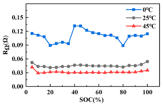
Figure 5.
Identification results of RΩ at different temperatures.
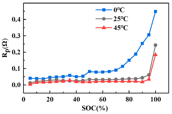
Figure 6.
Identification results of Rp at different temperatures.
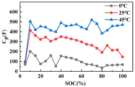
Figure 7.
Identification results of Cp at different temperatures.
The OCV test for the Li-ion battery yields data regarding the relationship between battery OCV and SOC at various temperatures. The fitting procedure involves utilizing Equations (3) and (4), and the resulting fitted curves are depicted in Figure 8.
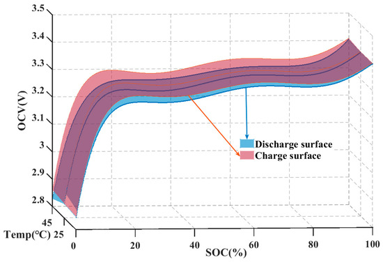
Figure 8.
Fitting relationship diagram of battery OCV, temperature, and SOC.
Figure 8 portrays the relationship between battery OCV, SOC, and temperature. Remarkably, the fitting for the 0 °C temperature condition exhibits a high accuracy with a value of 0.998. To assess the validity of the proposed equations (Equations (3) and (4)), OCV tests were conducted on the battery at three different temperatures: 0 °C, 25 °C, and 45 °C. The comparative results between the experimental data and the fitted data are presented in Table 1.

Table 1.
Prediction error.
3. SOC Estimation Based on Adaptive Sliding Mode Observer with Simplified Hysteresis Models during Electric Vehicle Duty Cycles
Complex operating conditions and temperature changes in electric vehicles impact the battery equivalent circuit model parameter RC, resulting in dynamic variations in the model’s parameters and subsequently influencing the accuracy of SOC estimation. The proposed adaptive sliding mode observer is a state observer characterized by ease of convergence, insensitivity to parameters, and low computational intensity. It considers the convergence speed of SOC estimation in lithium-iron-phosphate batteries, enhancing robustness to accommodate dynamic changes in model parameters under complex operating conditions.
3.1. Adaptive Sliding Mode Observer Design
Firstly, in order to achieve SOC estimation using an adaptive sliding mode observer, it is necessary to establish the mathematical model of lithium-iron-phosphate battery system and derive the state space equation. Subsequently, the design of a corresponding sliding mode observer is conducted to observe the battery’s state variables for SOC estimation. The state equation of the battery system can be obtained by following the derivation process outlined in Equation (1):
Here, , , , .
If the inputs and outputs of the circuit model are defined as and , respectively, the system state variables are selected as , , and . Then the equation of state can be succinctly expressed in terms of a matrix as:
Here, , , , .
Unknown parameter indicates the bounded uncertainty of each state quantity of the model.
Building upon this foundation, the conventional sliding mode observer is utilized to design the equivalent circuit model of the battery:
where is the observer gain, represents the error between the measured value of the terminal voltage and the estimated value on the sliding mode surface, and represents the error in reconstructing the state values. The saturation function is defined as . By referring to Equations (6) and (9), we can obtain:
The stability of the designed sliding mode observer is analyzed by assuming the existence of a positive definite symmetric matrix that satisfies the condition holds. In this case, the error dynamic equation is asymptotically stable.
Proof: we select the following Lyapunov function:
The derivation of Equation (9) results in:
When the value of observer gain exceeds the magnitude of the bounded unknown perturbation, when , , when , ,
In summary, if , then , i.e., the observation error has the ability to asymptotically converge to 0, i.e., . Based on the aforementioned analysis and results, it can be concluded that the adaptive sliding mode observer designed by Equation (7) exhibits stability.
However, the traditional sliding mode observer exhibits poor adaptability, leading to the issue of jitter caused by the discontinuity of the switching action. Lowering the observer gain reduces the size of the jitter, but excessively low gain hampers the convergence speed of the observer. Moreover, when the model parameters and uncertainty increase significantly, the low gain causes dispersion in observer estimation. Consequently, this paper proposes an adaptive sliding mode observer to enhance its adaptivity.
First, , , is the observer gain, which has the following advantages:
- (1)
- The observer achieves fast convergence when the estimated output voltage deviates significantly from the sliding mode surface, indicated by a larger value of . In this scenario, approaches due to , resulting in an increase in the value of . This increase signifies an accelerated convergence towards the sliding mode surface and enhances the observer’s convergence speed.
- (2)
- When the estimated output voltage approaches the sliding mode surface, indicated by a small value of , the observer’s jitter can be suppressed. At this point, closely approximates , leading to a gradual decrease in its value. Consequently, the observer’s jitter is effectively suppressed.
Despite the capability of the sliding mode gain design to mitigate some of the jitter effects, the use of a sign function as the saturation function (as shown in Figure 9) introduces high-frequency jitter due to its inherent discontinuous nature. To address this issue, this paper proposes the replacement of the saturation function with a sinusoidal saturation function (as depicted in Equation (11)) for further attenuation of the jitter [44].
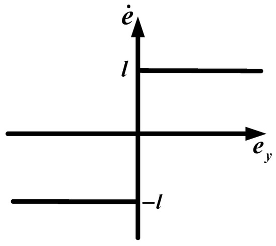
Figure 9.
Symbolic saturation function.
represents the thickness of the boundary layer. The saturation function, as depicted in Figure 10, exhibits smooth continuity attributed to the nonlinear sinusoidal function, thereby altering the sliding mode convergence law within the boundary layer. The greater the thickness of the boundary layer, the more pronounced the suppression of jitter vibrations. However, excessively thick boundary layers result in a reduced action area due to the high gain of the switching function, thereby impacting the response speed of the soft-switching sliding-mode observer. Nevertheless, the paper’s variable sliding-mode gain design mitigates the impact on response speed to some extent, even in the presence of a large boundary layer. This alleviation contributes to jitter vibration suppression, and when combined, the two factors enhance the adaptivity of the sliding-mode observer.
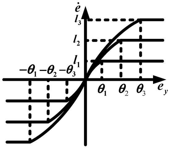
Figure 10.
Sinusoidal saturation function.
3.2. Implementation of SOC Estimation Method Based on Adaptive Sliding Mode Observer with Simplified Hysteresis Model
Figure 11 illustrates the system block diagram of the proposed adaptive sliding mode observer method, which aims to estimate the SOC of Li-ion batteries. The sliding mode observer exhibits strong robustness against parameter changes due to the system structure of the sliding mode control. This control system dynamically switches the controller structure based on the current state of the sliding mode surface during the sliding mode process. Consequently, the system slides along the designed sliding mode surface, independent of the battery’s parameter changes. As a result, this approach minimizes the impact of parameter identification errors on SOC estimation. Additionally, the offline identification of parameters for modeling allows for a reduction in the computational complexity of the battery management system while maintaining the estimation accuracy.
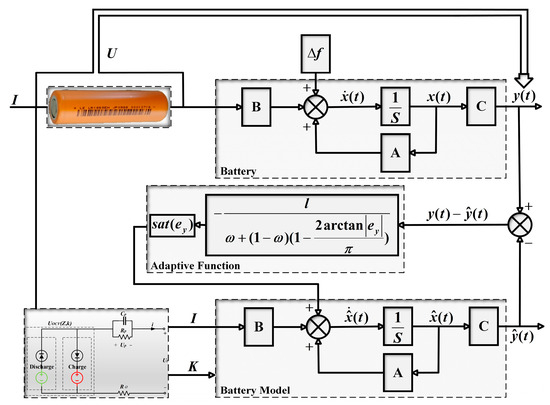
Figure 11.
Structure diagram of Thevenin equivalent circuit model self-adaption sliding mode observer.
Firstly, the electrical model parameters identified at room temperature of 25 °C are selected to establish the equivalent circuit model. By applying the same current to both the real battery and the model battery, the detected terminal voltage is compared with the estimated terminal voltage obtained from the observer. The resulting error value is then used to correct the observed value , which represents the real-time SOC of the lithium battery. Subsequently, the experimental results are presented in the following section to demonstrate the effectiveness of the proposed method in estimating SOC.
4. Experimental Research
The experimental subject of this study is the Cylindrical Lithium-ion Cell (LR18650EH) manufactured by Tianjin Lishen. The battery parameters are presented in Table 2. The experimental setup comprises a battery cycle charger (Arbin, model LBT5V30A) with an operating current range of −30 A to 30 A and an operating voltage range of −5 V to 5 V. Additionally, a high and low-temperature chamber (model DHTM-27-40-P-SD) is utilized, with a thermostat temperature range spanning from −40 °C to 180 °C. Figure 12 illustrates the experimental setup and battery samples. To ensure uniformity in battery parameters, LR18650EH batteries with similar aging degrees were carefully chosen for the experiments. Considering the operating temperature range of the battery management system (BMS) and the constant temperature range of the experimental equipment, the battery temperatures in this study are set to 0 °C, 25 °C, and 45 °C.

Table 2.
Specification of the LR18650EH cell.
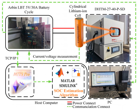
Figure 12.
The experiment equipment.
4.1. Comparison of the Accuracy of Simplified Hysteresis Model and Ordinary Model under Different Working Conditions Validation
To assess the accuracy of the proposed simplified hysteresis model compared to the general model, we selected the test point at room temperature (25 °C) for the battery condition experiment. The dynamic stress test (DST) condition current and federal urban driving schedule (FUDS) were employed as excitations, and the battery parameters obtained from offline parameter identification in Section II were utilized to validate the accuracy of both battery models. As illustrated in Figure 13 and Figure 14, the graphs display the current excitation and battery voltage response curves for the DST and FUDS conditions, respectively.
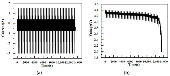
Figure 13.
Power curve of DST. (a) DST Current. (b) DST Voltage.
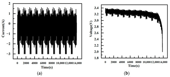
Figure 14.
Power curve of FUDS. (a) FUDS Current. (b) FUDS Voltage.
Inputting the dynamic stress test data into the battery model yields the voltage response of both battery models at 25 °C, as depicted in Figure 15. The figure illustrates that the hysteresis model’s voltage closely aligns with the actual battery voltage, particularly during the battery charging stage. However, the voltage response of the conventional model is comparatively inferior. In both models, when the battery operating current is in the discharge condition, their voltage responses are identical. Yet, the conventional model solely relies on the OCV curve during battery discharge, without filtering the battery’s hysteresis characteristics related to open-circuit voltage differences. This results in significant voltage fluctuations in the battery charging stage, affecting the model accuracy. The hysteresis model considers the voltage hysteresis property, ensuring a superior voltage tracking capability across all stages of current charging and discharging. This results in a higher accuracy in fitting the voltage response.
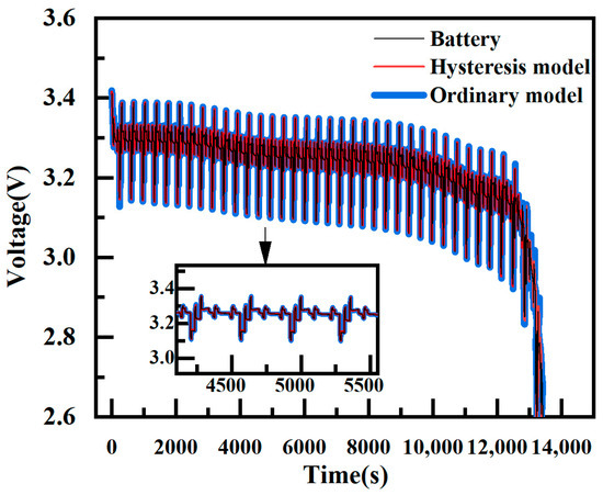
Figure 15.
Estimated terminal voltage of hysteresis model and ordinary model.
In Figure 16, the end voltage fitting errors of the two models are displayed, highlighting the discernible difference between them. The hysteresis model’s terminal voltage error is typically within 0.035V, while the normal model’s error is typically within 0.06V. Examining the figure, it becomes apparent that during the charging stage of the working current, the error is lower than that of the ordinary model. This is attributed to the hysteresis model’s consideration of the battery’s charging stage. In the discharging stage, although the difference between the errors of the two models is not substantial, the ordinary model, limited to the OCV stage during discharging, fails to attain the actual voltage after charging. Consequently, the discharge results in a lower voltage plateau and more pronounced jitter at the end of the battery discharge. The fitting error of the terminal voltage at the end of SOC, where polarization is pronounced, even exceeds 0.08V.
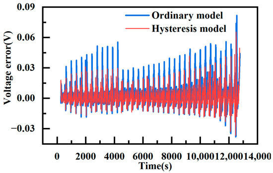
Figure 16.
Voltage error of hysteresis model and ordinary model.
Table 3 presents the statistical results for the terminal voltage error fitting of the two models. The Absolute Value of Maximum Error () represents the maximum absolute error. Mean Absolute Error () provides insight into the actual model output error, while Root Mean Square Error () quantifies the degree of deviation between the model output voltage and the actual voltage. For these metrics, the formulas for and are expressed as follows:

Table 3.
Voltage-fitting statistical results of two models at 25 °C.
A comparison of the statistics for the fitted voltage errors reveals that the MAE and RMSE of the hysteresis model are smaller than those of the conventional model. The latter is nearly twice as high as the former in these two data metrics.
Inputting the federal urban driving schedule data into the battery model yields the voltage response of both battery models at 25 °C, as depicted in Figure 17. Observing the figure, it is evident that the voltage of the hysteresis model aligns slightly better with the actual battery voltage, especially in the battery charging stage where the hysteresis model’s voltage is closer to the real value. The voltage response of the conventional model is comparatively inferior. In the full cycle of the battery condition, the hysteresis model exhibits better voltage-following characteristics and achieves higher voltage response-fitting accuracy.
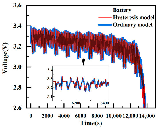
Figure 17.
Estimated terminal voltage of hysteresis model and ordinary model.
In Figure 18, the end-voltage fitting error for the federal urban driving schedule is depicted for both models, revealing the discernible difference between them. The hysteresis model’s terminal voltage error is typically within 0.045 V, while the normal model’s error is typically within 0.09 V. The figure clearly shows that the end voltage error of the hysteresis model is lower than that of the conventional model during the charging stage of the working current. The maximum error of the conventional model exceeds that of the hysteresis model by approximately 0.034 V, and the difference in error during the discharging stage is not substantial. Furthermore, the figure indicates that the errors of both models are elevated under this condition. This phenomenon is attributed to the large current used in the federal urban driving schedule, causing the internal temperature increase in the battery. This temperature rise may lead to changes in the parameters of the battery model, thereby affecting the accuracy of the output voltage. This suggests that the parameters of the battery model are susceptible to the influence of the external environment, leading to parameter uncertainty.
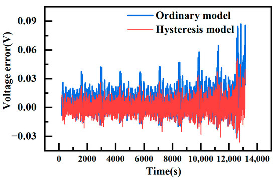
Figure 18.
Voltage error of hysteresis model and ordinary model.
As shown in Table 4, a comparison of the statistics for the fitting voltage errors of the two models reveals that the MAE and RMSE of the hysteresis model are smaller than those of the conventional model. This indicates that the hysteresis model consistently maintains better fitting accuracy of the voltage output.

Table 4.
Voltage-fitting statistical results of two models at 25 °C.
4.2. Comparative Validation of SOC Estimates
To validate the performance of the proposed SOC estimation algorithm based on the adaptive sliding mode observer, tests are conducted using the dynamic stress test (DST) and federal urban driving schedule (FUDS) operating conditions data. These tests are repeated across three sets of experiments at 0 °C, 25 °C, and 45 °C. Throughout all subsequent test experiments, the hysteresis model proposed in this paper is employed across all models. The cut-off parameters are uniformly selected from the same offline identification parameters at 25 °C, with initial SOC values set consistently at 80%. The sliding mode observer algorithm (SMO) and extended Kalman filter (EKF) algorithms are introduced for comparison against the adaptive sliding mode observer (ASMO) algorithm.
Figure 19 illustrates the SOC estimation results of the three algorithms based on the DST and FUDS test data at 25 °C. It is evident from the figure that both ASMO and EKF exhibit better estimations with a higher degree of fit and smaller errors. However, the SMO algorithm demonstrates poorer estimation accuracy with significant fluctuations around the true value and large jitter. In comparison, ASMO exhibits smaller jitter. Additionally, considering their identical initial values, it is apparent that both ASMO and SMO converge faster than EKF, with ASMO demonstrating faster convergence than SMO.
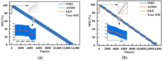
Figure 19.
SOC estimation results at 25 °C. (a) DST condition. (b) DST condition.
Figure 20 presents the SOC estimation errors of the three algorithms at 25 °C based on DST and FUDS. It is evident that both the adaptive sliding mode observer algorithm and the extended Kalman filter exhibit relatively high accuracy in SOC estimation at 25 °C. However, the sliding mode observer algorithm has the lowest estimation accuracy compared to the former. The estimation errors are as follows: SMO at of DST and of FUDS, ASMO at of DST and of FUDS, and EKF at of DST and of FUDS. It is notable that the accuracy of EKF is almost the same as that of ASMO, with a smoother error profile. At the end of the SOC estimation, the AVME is 5.33% for SMO, 2.31% for ASMO, and 1.07% for EKF, all of which are close in accuracy.
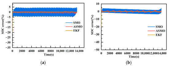
Figure 20.
SOC estimation error results at 25 °C. (a) DST error results. (b) FUDS error results.
Figure 21 illustrates the SOC estimation results of the three algorithms based on the dynamic stress test (DST) and federal urban driving schedule (FUDS) data at 45°C. It is evident from the figure that the adaptive sliding mode observer algorithm (ASMO) continues to maintain a better estimation effect, exhibiting a higher degree of fitting and a smaller error. The estimation accuracy of the sliding mode observer algorithm (SMO), although experiencing a certain degree of degradation, still performs better with some fluctuations around the true value and larger jitter. In contrast, ASMO demonstrates a smaller jitter. The extended Kalman filter algorithm (EKF), on the other hand, exhibits significant deviation in estimation, even showing a tendency to diverge, particularly at the end of the SOC where a larger estimation error occurs. This deviation is attributed to the fact that the EKF’s model parameters are derived from offline identification at 25°C, making it more sensitive to model accuracy, resulting in SOC estimation deviation. However, given the experimental temperature of 45 °C, where model parameters change less compared to those at 25 °C, EKF shows a relatively small deviation. Considering their identical initial values, it is apparent that the convergence speed of ASMO and SMO remains faster than that of EKF, with ASMO demonstrating faster convergence than SMO.
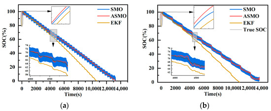
Figure 21.
SOC estimation results at 45 °C. (a) DST condition. (b) DST condition.
Figure 22 displays the SOC estimation errors of the three algorithms at 45 °C based on the dynamic stress test (DST) and federal urban driving schedule (FUDS) data. It is evident that the accuracy of the SOC estimation results of the adaptive sliding mode observer algorithm (ASMO) remains relatively high at 45 °C. The estimation accuracy of the sliding mode observer algorithm (SMO) is somewhat reduced, but it exhibits significant fluctuations only at the end of SOC, remaining consistent with its performance at 25 °C in other stages. This suggests that SMO and ASMO are insensitive to changes in model parameters, maintaining good estimation accuracy and indicating their high robustness. Specifically, the estimation error of SMO is at of DST and of FUDS, the estimation error of ASMO is at of DST and of FUDS, and the estimation error of the extended Kalman filter (EKF) algorithm varies significantly at of DST and of FUDS. It is apparent that the error of EKF surpasses that of ASMO and is comparable to SMO. At the end of the SOC estimation, the AVME is 6.25% for SMO, 4.00% for ASMO, and 22.34% for EKF.
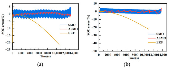
Figure 22.
SOC estimation error results at 45 °C. (a) DST error results. (b) FUDS error results.
Figure 23 illustrates the SOC estimation results of the three algorithms based on the DST and FUDS test data at 0 °C. It is evident from the figure that the adaptive sliding mode observer algorithm (ASMO) maintains a superior estimation effect, exhibiting a higher degree of fit. The estimation accuracy of the sliding mode observer algorithm (SMO) algorithm remains comparable to the first two temperatures, with minimal change. SMO consistently hovers near the true value but exhibits significant jitter. ASMO, on the other hand, shows a smaller jitter. However, the extended Kalman filter (EKF) experiences a considerable deviation in estimation and demonstrates a divergence condition, particularly at the end of the SOC where a significant deviation occurs. This deviation is attributed to the fact that the EKF’s model parameters are derived from offline identification at 25 °C, making it more sensitive to model accuracy, resulting in SOC estimation bias. At this point in time, with the experimental temperature at 0 °C, the model parameters vary considerably compared to those at 25 °C, leading to a substantial deviation in EKF and a premature drop to the endpoint. At this low temperature, considering their identical initial values, it is apparent that ASMO and SMO still converge faster than EKF. Among them, ASMO converges faster compared with SMO, and EKF appears to diverge.
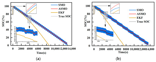
Figure 23.
SOC estimation results at 0 °C. (a) DST condition. (b) DST condition.
Figure 24 presents the SOC estimation errors of the three algorithms at 0 °C based on the dynamic stress test and federal urban driving schedule data. Notably, at 0 °C, the accuracy of SOC estimation results for the adaptive sliding mode observer algorithm (ASMO) remains relatively high. Despite significant changes in the battery model parameters at 0 °C, the estimation accuracies of ASMO and the sliding mode observer algorithm (SMO) remain consistent with those at 25 °C and 45 °C, indicating robust estimation capabilities. This further emphasizes that SMO and ASMO are insensitive to changes in model parameters and maintain high robustness in their estimation accuracies. Specifically, the estimation error of SMO is at of DST and of FUDS, the estimation error of ASMO is at of DST and of FUDS, and the estimation error of EKF varies significantly at of DST and of FUDS, with the error of EKF notably larger than that of SMO. At the end of the SOC estimation, the AVME is 4.65% for SMO, 3.09% for ASMO, and 45.84% for EKF.
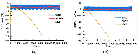
Figure 24.
SOC estimation error results at 0 °C. (a) DST error results. (b) FUDS error results.
As shown in Table 5, it can be seen that the ASMO algorithm proposed in this paper has the smallest error and the best SOC estimation under the two working conditions with different temperatures.

Table 5.
SOC estimation error when performing DST and FUDS at different temperatures.
5. Conclusions
This paper proposes the establishment of a battery model accounting for hysteresis characteristics. The model is combined with an improved adaptive sliding mode observer algorithm to achieve accurate estimation of the state of charge (SOC) in lithium-iron-phosphate batteries during electric vehicle duty cycles. The accuracy of the hysteresis model is experimentally verified under two different working conditions during electric vehicle duty cycles. The absolute value of maximum error (AVME) of the terminal voltage does not exceed 59.8mV, the mean absolute error (MAE) is up to 13.9mV, and the root mean square error (RMSE) is up to 31.2mV in the Dynamic Stress Test (DST). In the federal urban driving schedule, the AVME of the terminal voltage does not exceed 52.3mV, the MAE is up to 14.1mV, and the RMSE is up to 39.6mV. Especially during the charging stage, the error is more stable, reflecting better followability. Then, the estimation accuracy of the adaptive sliding mode observer algorithm (ASMO) was verified under different temperature conditions using DST and FUDS operating current. The MAE of SOC estimation with the ASMO algorithm is lower than others, improving SOC estimation accuracy more than that of the sliding mode observer algorithm (SMO), reducing jitter noticeably, and achieving faster convergence speed. The ASMO algorithm proves more tolerant to parameter variations caused by different temperatures and exhibits the best tracking performance of SOC, fast convergence, and overall good SOC tracking performance. In contrast, the extended Kalman filter (EKF) algorithm is more error-prone due to sensitivity to temperature parameter variations, model mismatch, and noise in the computation process. The ASMO algorithm overcomes these challenges by introducing the sliding mode surface and the adaptive factor, resulting in higher accuracy and stronger robustness. The above results demonstrate that SOC estimation in lithium-iron-phosphate batteries, based on an adaptive sliding mode observer with a simplified hysteresis model, exhibits high robustness and can achieve accurate estimation under variable temperature conditions during electric vehicle duty cycles.
Author Contributions
Conceptualization, Y.C. and R.L.; methodology, Y.C.; software, Y.C.; validation, Y.C., R.L., H.S. and X.Z.; formal analysis, Y.C. and R.L.; investigation, Y.C.; resources, Y.C. and R.L.; data curation, Y.C. and R.L.; writing—original draft preparation, Y.C. and R.L.; writing—review and editing, Y.C. and R.L.; visualization, Y.C. and H.S.; supervision, R.L., H.S. and X.Z.; project administration, Y.C. and R.L.; funding acquisition, R.L. All authors have read and agreed to the published version of the manuscript.
Funding
This research was funded by The Natural Science Foundation of Heilongjiang Province, China (LH2022E08) and The Fund Project of Technology Field (2023-JCJQ-JJ-0666).
Data Availability Statement
Data is contained within the article.
Conflicts of Interest
The authors declare no conflicts of interest.
References
- Zhang, Q.; Shang, Y.; Li, Y.; Cui, N.; Duan, B.; Zhang, C. A Novel Fractional Variable-Order Equivalent Circuit Model and Parameter Identification of Electric Vehicle Li-Ion Batteries. ISA Trans. 2020, 97, 448–457. [Google Scholar] [CrossRef]
- Ng, M.-F.; Zhao, J.; Yan, Q.; Conduit, G.J.; Seh, Z.W. Predicting the State of Charge and Health of Batteries Using Data-Driven Machine Learning. Nat. Mach. Intell. 2020, 2, 161–170. [Google Scholar] [CrossRef]
- Zhang, C.; Wang, L.Y.; Li, X.; Chen, W.; Yin, G.G.; Jiang, J. Robust and Adaptive Estimation of State of Charge for Lithium-Ion Batteries. IEEE Trans. Ind. Electron. 2015, 62, 4948–4957. [Google Scholar] [CrossRef]
- Trovão, J.P.; Machado, F.; Pereirinha, P.G. Hybrid Electric Excursion Ships Power Supply System Based on a Multiple Energy Storage System. IET Electr. Syst. Transp. 2016, 6, 190–201. [Google Scholar] [CrossRef]
- Mousazadeh Mousavi, S.Y.; Jalilian, A.; Savaghebi, M.; Guerrero, J.M. Autonomous Control of Current- and Voltage-Controlled DG Interface Inverters for Reactive Power Sharing and Harmonics Compensation in Islanded Microgrids. IEEE Trans. Power Electron. 2018, 33, 9375–9386. [Google Scholar] [CrossRef]
- Zhou, N.; Price, L.; Yande, D.; Creyts, J.; Khanna, N.; Fridley, D.; Lu, H.; Feng, W.; Liu, X.; Hasanbeigi, A.; et al. A Roadmap for China to Peak Carbon Dioxide Emissions and Achieve a 20% Share of Non-Fossil Fuels in Primary Energy by 2030. Appl. Energy 2019, 239, 793–819. [Google Scholar] [CrossRef]
- Hu, X.; Jiang, J.; Cao, D.; Egardt, B. Battery Health Prognosis for Electric Vehicles Using Sample Entropy and Sparse Bayesian Predictive Modeling. IEEE Trans. Ind. Electron. 2015, 63, 1. [Google Scholar] [CrossRef]
- Ye, M.; Hu, G.; Guo, F.; Huang, W.; Wang, Z.; Zhao, X.; Li, Y. A Novel Semi-Analytical Solution for Calculating the Temperature Distribution of the Lithium-Ion Batteries during Nail Penetration Based on Green’s Function Method. Appl. Therm. Eng. 2020, 174, 115129. [Google Scholar] [CrossRef]
- Chun, C.Y.; Cho, B.H.; Kim, J. Covariance Controlled State-of-Charge Estimator of LiFePO4 Cells Using a Simplified Hysteresis Model. Electrochim. Acta 2018, 265, 629–637. [Google Scholar] [CrossRef]
- Thele, M.; Bohlen, O.; Sauer, D.U.; Karden, E. Development of a Voltage-Behavior Model for NiMH Batteries Using an Impedance-Based Modeling Concept. J. Power Sources 2008, 175, 635–643. [Google Scholar] [CrossRef]
- Tan, B.Y.; Du, J.Y.; Ye, X.H.; Cao, X.; Zhai, C. Overview of SOC estimation methods for lithium-ion batteries based on model. Sci. Technol. 2023, 12, 1995–2010. [Google Scholar] [CrossRef]
- Wei, Z.; Zou, C.; Leng, F.; Soong, B.H.; Tseng, K.-J. Online Model Identification and State-of-Charge Estimate for Lithium-Ion Battery With a Recursive Total Least Squares-Based Observer. IEEE Trans. Ind. Electron. 2018, 65, 1336–1346. [Google Scholar] [CrossRef]
- Feng, Y.; Xue, C.; Han, Q.-L.; Han, F.; Du, J. Robust Estimation for State-of-Charge and State-of-Health of Lithium-Ion Batteries Using Integral-Type Terminal Sliding-Mode Observers. IEEE Trans. Ind. Electron. 2020, 67, 4013–4023. [Google Scholar] [CrossRef]
- Plett, G.L. Extended Kalman Filtering for Battery Management Systems of LiPB-Based HEV Battery Packs. J. Power Sources 2004, 134, 262–276. [Google Scholar] [CrossRef]
- Hosseininasab, S.; Momtaheni, N.; Pischinger, S.; Günther, M.; Bauer, L. State-of-Charge Estimation of Lithium-Ion Batteries Using an Adaptive Dual Unscented Kalman Filter Based on a Reduced-Order Model. J. Energy Storage 2023, 73, 109011. [Google Scholar] [CrossRef]
- Wu, L.; Lyu, Z.; Huang, Z.; Zhang, C.; Wei, C. Physics-Based Battery SOC Estimation Methods: Recent Advances and Future Perspectives. J. Energy Chem. 2024, 89, 27–40. [Google Scholar] [CrossRef]
- Pan, H.; Lü, Z.; Lin, W.; Li, J.; Chen, L. State of Charge Estimation of Lithium-Ion Batteries Using a Grey Extended Kalman Filter and a Novel Open-Circuit Voltage Model. Energy 2017, 138, 764–775. [Google Scholar] [CrossRef]
- Cheng, Z.; Lv, J.; Liu, Y.; Yan, Z. Estimation of State of Charge for Lithium-Ion Battery Based on Finite Difference Extended Kalman Filter. J. Appl. Math. 2014, 2014, 348537. [Google Scholar] [CrossRef]
- Chen, Z.; Yang, L.; Zhao, X.; Wang, Y.; He, Z. Online State of Charge Estimation of Li-Ion Battery Based on an Improved Unscented Kalman Filter Approach. Appl. Math. Model. 2019, 70, 532–544. [Google Scholar] [CrossRef]
- Liu, G.; Xu, C.; Li, H.; Jiang, K.; Wang, K. State of Charge and Online Model Parameters Co-Estimation for Liquid Metal Batteries. Appl. Energy 2019, 250, 677–684. [Google Scholar] [CrossRef]
- Cui, X.; Jing, Z.; Luo, M.; Guo, Y.; Qiao, H. A New Method for State of Charge Estimation of Lithium-Ion Batteries Using Square Root Cubature Kalman Filter. Energies 2018, 11, 209. [Google Scholar] [CrossRef]
- Zhao, Y. Performance Evaluation of Cubature Kalman Filter in a GPS/IMU Tightly-Coupled Navigation System. Signal Process. 2016, 119, 67–79. [Google Scholar] [CrossRef]
- Chen, X.-K.; Sun, D. Modeling and State of Charge Estimation of Lithium-Ion Battery. Adv. Manuf. 2015, 3, 202–211. [Google Scholar] [CrossRef]
- Wu, Z.; Wang, G.; Xie, Z.; He, Y.; Lu, X. Lithium Battery SOC Estimation Based on Whale Optimization Algorithm and Unscented Kalman Filter. J. Renew. Sustain. Energy 2020, 12, 065501. [Google Scholar] [CrossRef]
- Jia, W.; Sun, X.; Lin, M.; Wang, C.; Du, H.; Chen, P.; Liu, Z. Model Improvement and SOC Estimation Based on Aluminium Ion Batteries. Eng. Res. Express 2021, 3, 015038. [Google Scholar] [CrossRef]
- Su, D.; Chen, X.K. Charge State Estimation of Li-ion Batteries Based on Discrete-time Sliding Mode Observers. Proc. CSEE 2015, 35, 185–191. [Google Scholar] [CrossRef]
- Sui, X.; Chen, Y.; Zhang, X.H.; Liu, D. Improved sliding mode observer for state of charge estimation of lithium-ion battery. Adv. Technol. Electr. Eng. Energy 2018, 37, 73–82. [Google Scholar] [CrossRef]
- Nath, A.; Gupta, R.; Mehta, R.; Bahga, S.S.; Gupta, A.; Bhasin, S. Attractive Ellipsoid Sliding Mode Observer Design for State of Charge Estimation of Lithium-Ion Cells. IEEE Trans. Veh. Technol. 2020, 69, 14701–14712. [Google Scholar] [CrossRef]
- Sui, X.; He, S.; Stroe, D.-I.; Huang, X.; Meng, J.; Teodorescu, R. A Review of Sliding Mode Observers Based on Equivalent Circuit Model for Battery SoC Estimation. In Proceedings of the 2019 IEEE 28th International Symposium on Industrial Electronics (ISIE), Vancouver, BC, Canada, 12–14 June 2019; IEEE: New York, NY, USA, 2019; pp. 1965–1970. [Google Scholar]
- Xiong, B.; Zhao, J.; Su, Y.; Wei, Z.; Skyllas-Kazacos, M. State of Charge Estimation of Vanadium Redox Flow Battery Based on Sliding Mode Observer and Dynamic Model Including Capacity Fading Factor. IEEE Trans. Sustain. Energy 2017, 8, 1658–1667. [Google Scholar] [CrossRef]
- Chen, X.; Shen, W.X.; Cao, Z.; Kapoor, A. Sliding Mode Observer for State of Charge Estimation Based on Battery Equivalent Circuit in Electric Vehicles. Aust. J. Electr. Electron. Eng. 2012, 9, 225–234. [Google Scholar] [CrossRef]
- Gholizadeh, M.; Salmasi, F.R. Estimation of State of Charge, Unknown Nonlinearities, and State of Health of a Lithium-Ion Battery Based on a Comprehensive Unobservable Model. IEEE Trans. Ind. Electron. 2014, 61, 1335–1344. [Google Scholar] [CrossRef]
- Kim, D.; Koo, K.; Jeong, J.; Goh, T.; Kim, S. Second-Order Discrete-Time Sliding Mode Observer for State of Charge Determination Based on a Dynamic Resistance Li-Ion Battery Model. Energies 2013, 6, 5538–5551. [Google Scholar] [CrossRef]
- Ning, B.; Cao, B.; Wang, B.; Zou, Z. Adaptive Sliding Mode Observers for Lithium-Ion Battery State Estimation Based on Parameters Identified Online. Energy 2018, 153, 732–742. [Google Scholar] [CrossRef]
- Xu, J.; Mi, C.C.; Cao, B.; Deng, J.; Chen, Z.; Li, S. The State of Charge Estimation of Lithium-Ion Batteries Based on a Proportional-Integral Observer. IEEE Trans. Veh. Technol. 2014, 63, 1614–1621. [Google Scholar] [CrossRef]
- Chen, X.; Shen, W.; Dai, M.; Cao, Z.; Jin, J.; Kapoor, A. Robust Adaptive Sliding-Mode Observer Using RBF Neural Network for Lithium-Ion Battery State of Charge Estimation in Electric Vehicles. IEEE Trans. Veh. Technol. 2016, 65, 1936–1947. [Google Scholar] [CrossRef]
- Kim, I.-S. The Novel State of Charge Estimation Method for Lithium Battery Using Sliding Mode Observer. J. Power Sources 2006, 163, 584–590. [Google Scholar] [CrossRef]
- Wehbe, J.; Karami, N. Battery Equivalent Circuits and Brief Summary of Components Value Determination of Lithium Ion: A Review. In Proceedings of the 2015 Third International Conference on Technological Advances in Electrical, Electronics and Computer Engineering (TAEECE), Beirut, Lebanon, 29 April–1 May 2015; IEEE: New York, NY, USA, 2015; pp. 45–49. [Google Scholar]
- Kwak, M.; Lkhagvasuren, B.; Park, J.; You, J.-H. Parameter Identification and SOC Estimation of a Battery Under the Hysteresis Effect. IEEE Trans. Ind. Electron. 2020, 67, 9758–9767. [Google Scholar] [CrossRef]
- Tran, M.-K.; Mevawala, A.; Panchal, S.; Raahemifar, K.; Fowler, M.; Fraser, R. Effect of Integrating the Hysteresis Component to the Equivalent Circuit Model of Lithium-Ion Battery for Dynamic and Non-Dynamic Applications. J. Energy Storage 2020, 32, 101785. [Google Scholar] [CrossRef]
- Zhu, L.; Sun, Z.; Dai, H.; Wei, X. A Novel Modeling Methodology of Open Circuit Voltage Hysteresis for LiFePO4 Batteries Based on an Adaptive Discrete Preisach Model. Appl. Energy 2015, 155, 91–109. [Google Scholar] [CrossRef]
- Chen, S.; Kang, X.; Zhu, Z.X.; Zhang, Y.J.; Han, X. Polarization Voltage Error Correction Considering Battery’s Hysteresis Effect. Power Syst. Technol. 2020, 44, 316–322. [Google Scholar] [CrossRef]
- Kim, J.; Seo, G.-S.; Chun, C.; Cho, B.-H.; Lee, S. OCV Hysteresis Effect-Based SOC Estimation in Extended Kalman Filter Algorithm for a LiFePO4/C Cell. In Proceedings of the 2012 IEEE International Electric Vehicle Conference, Greenville, SC, USA, 4–8 March 2012; IEEE: New York, NY, USA, 2012; pp. 1–5. [Google Scholar]
- Lu, X.Q.; Lin, H.Y.; Feng, Y.; Han, J.L. Soft Switching Sliding Mode Observer for PMSM Sensorless Control. Trans. China Electrotech. Soc. 2015, 30, 106–113. [Google Scholar] [CrossRef]
Disclaimer/Publisher’s Note: The statements, opinions and data contained in all publications are solely those of the individual author(s) and contributor(s) and not of MDPI and/or the editor(s). MDPI and/or the editor(s) disclaim responsibility for any injury to people or property resulting from any ideas, methods, instructions or products referred to in the content. |
© 2024 by the authors. Licensee MDPI, Basel, Switzerland. This article is an open access article distributed under the terms and conditions of the Creative Commons Attribution (CC BY) license (https://creativecommons.org/licenses/by/4.0/).
