Abstract
This paper showcases the integration of the Interfacing Toolbox for Robotic Arms (ITRA) with our newly developed hybrid Visual Servoing (VS) methods to automate the disassembly of electric vehicle batteries, thereby advancing sustainability and fostering a circular economy. ITRA enhances collaboration between industrial robotic arms, server computers, sensors, and actuators, meeting the intricate demands of robotic disassembly, including the essential real-time tracking of components and robotic arms. We demonstrate the effectiveness of our hybrid VS approach, combined with ITRA, in the context of Electric Vehicle (EV) battery disassembly across two robotic testbeds. The first employs a KUKA KR10 robot for precision tasks, while the second utilizes a KUKA KR500 for operations needing higher payload capacity. Conducted in T1 (Manual Reduced Velocity) mode, our experiments underscore a swift communication protocol that links low-level and high-level control systems, thus enabling rapid object detection and tracking. This allows for the efficient completion of disassembly tasks, such as removing the EV battery’s top case in 27 s and disassembling a stack of modules in 32 s. The demonstrated success of our framework highlights its extensive applicability in robotic manufacturing sectors that demand precision and adaptability, including medical robotics, extreme environments, aerospace, and construction.
1. Introduction
Lithium-ion batteries (LIBs) are increasingly significant in today’s society, integral in everything from mobile phones to energy storage systems in renewable energy sources, and play a crucial role in the electric vehicle (EV) industry. This has raised concerns about the recycling and reuse of LIBs. Consequently, the industrial sector has seen a growing demand for disassembly solutions driven by environmental objectives and recent regulations. This scenario necessitates real-time adaptability in disassembly, especially in high-force industrial settings where constant vigilance for changes is essential. This study employs various case scenarios for autonomously disassembling and real-time tracking of battery components, focusing on industrial robotic applications in this area.
Despite the widespread adoption of lithium-ion batteries in electric vehicles, the disassembly of these batteries is not yet fully automated within the industry. Automation is needed to mitigate safety risks associated with manual disassembly processes. Moreover, automating disassembly aligns with the NetZero2050 strategies, which aim to preserve critical materials and support the circular economy by enhancing the efficiency of EV recycling.
Robotic manufacturing is traditionally thought of as involving structured tasks characterized by repetition. Major industrial robot suppliers offer proprietary programming languages to enable operators to set up assembly tasks for manufacturing lines [1]. However, challenges and bottlenecks in efficiency arise in chaotic and unstructured manufacturing scenarios, such as disassembly tasks. Traditional programming methods for robot manipulators are inefficient in dealing with variability, which is a challenge for LIBs due to their diversity in models, sizes, shapes, and conditions [2]. Various actions like cutting, pulling, unbolting, and sorting are often required for disassembly, leading to complex systems with various sensors and actuators.
The process of EV battery disassembly is challenging due to the diversity in battery designs, the lack of prior knowledge about each battery’s condition, and the absence of detailed design information from OEMs. Necessitating robust sensory feedback mechanisms, including vision and force feedback, to enhance perception and accuracy during the disassembly process.
Several toolboxes have been developed to enhance system integration, incorporating sensors, actuators, and software [3,4,5,6]. However, many of these toolboxes are limited in capabilities or were designed for outdated generations of robot controllers, requiring advanced technical and programming skills. Despite these limitations, such toolboxes are crucial for system integration, particularly for advanced tasks like disassembly.
Vision sensors are among the most commonly used, providing feedback about environments without physical contact, making them essential for working in unstructured and uncertain environments [7]. In control tasks, vision sensors identify a goal in the environment and then calculate the optimal path to move the robot towards the goal, avoiding joint limits and singularities [8]. Visual Servoing (VS) involves using data from vision sensors for closed-loop dynamic control of a robot to achieve its goal. Various VS approaches in robotics have been tried to address industrial challenges [9,10] with mixed success, nevertheless demonstrating their potential in adapting to dynamic scenarios, which is the case for disassembly tasks.
This study extends the Interfacing Toolbox for Robotic Arms (ITRA) with real-time adaptive behavior capabilities from our previous paper [11]. ITRA enables real-time control and hardware integration for fourth-generation KUKA robot controllers. The extension includes multiple VS algorithms, particularly our Decoupled Hybrid Visual Servoing (DHVS) and object-based trackers. Our previous paper [12] demonstrated that DHVS performs better than classical VS approaches to address the industrial challenge of battery disassembly.
This interfacing in industrial robots is required for managing complex disassembly tasks, especially those requiring the manipulation of high payloads, such as lifting batteries weighing around 300 kg and full of uncertainties. This research is a step to contribute to environmental sustainability, and our solutions applied to industrial settings can also be a step towards a circular economy, particularly in EV recycling at an industrial scale. Scientifically, the study advances our understanding of adaptive robotic behaviours in high-variability environments, showing the feasibility of integrating advanced control algorithms and sensory feedback for real-world applications with giant industrial manipulators.
The present paper is structured as follows: Section 2 discusses related works in real-time control of industrial robots and visual servoing. Section 3 presents the methodology and background knowledge with a description of the robotic setup needed for the experiment. Section 4 proceeds to present the experiments and case studies to test the framework in precision and speed tasks using the KR10 robot and high-force requiring tasks using the KR500 robot. Section 5 presents and discusses the results across the different scenarios. Finally, Section 6 concludes with insights from the study on battery disassembly and directions for future work in the area.
2. Related Works
Several areas relevant to the paper need to be tackled before discussing the battery disassembly task we are performing and how the combination of DHVS and ITRA can help address these challenges.
2.1. Battery Disassembly
Recent research in robotic battery disassembly has unveiled complexities and challenges in automating this process due to inherent uncertainties. Zhang et al. developed an autonomous system for disassembling electric vehicle batteries, achieving high success in laboratory settings and demonstrating efficiency and autonomy in controlled environments [13]. Xiao et al. investigated optimizing EV battery disassembly through multi-agent reinforcement learning, focusing on the dynamic nature of the process and the importance of human–robot collaboration [14], which our integrated framework allows. Gerlitz et al. enhanced precision in identifying crucial points during LIBs module disassembly using computer vision and 3D camera-based localization, addressing accurate component handling challenges [15], with our DHVS algorithm also allowing 3D localization, optimized for handling the battery components. Hathaway et al. explored real-time teleoperation of collaborative robots (cobots) for EV battery disassembly, noting time-saving benefits and compromises in first-attempt success rates [16]. ITRA enables real-time control for KUKA industrial robots, potentially allowing the replication of Hathaway’s approach with traditional (non-collaborative) robotic manipulators. These studies show the evolving landscape of robotic disassembly in unpredictable environments, like EV battery disassembly. This shows the need for adaptable, precise, and collaborative robotic solutions in areas where a real-time adaptive toolbox like ITRA could be beneficial.
2.2. System Integration Toolboxes
The application of industrial robots in manufacturing, especially in the Industry 4.0 era, presents unique opportunities for disassembly, aided by toolboxes that permit better control of manipulators. Fitka et al. developed a training tool for operating and programming KUKA industrial robots, offering practical and educational insights for integrating these robots into industrial setups [3]. Mišković et al. proposed combining a cloud-based system, a prototyped mobile robot, and an ABB IRB 140 industrial robot, demonstrating potential advancements in factory automation [4]. Golz et al. introduced the RoBO-2L Matlab Toolbox, enabling the extended offline programming of KUKA robots and integration with unsupported peripheral hardware and software [5].
Additionally, various toolboxes have been developed for specific purposes and platforms. These include the Matlab-based Robotics and Fuzzy Logic Toolboxes [17], the Finite Element Method for the dynamic modelling of flexible manipulators [18], and the Epipolar Geometry Toolbox (EGT) for multi-camera system visual information management [19]. Other notable contributions are Corke’s toolbox for robotic manipulators [20], KUKA Sunrise Toolbox (KST) [21], the KUKA control toolbox (KCT) [6], among others like Robot Operating System (ROS) [22] and the robotics toolbox for Python [23]. These toolboxes cater to a wide range of needs, from basic modelling and simulation to complex control scenarios in robotic systems, often requiring specialized knowledge in areas like MATLAB programming or finite element analysis.
The ITRA toolbox has been designed to enable the seamless integration of industrial robotic arms with server computers, sensors, and actuators, providing a platform that is both highly adaptable and extendable [11]. It has extensively been adopted in robotic non-destructive testing applications [24,25]. It enables real-time adaptive robotic responses and the control of multiple robots simultaneously. Whereas ROS and ROS2 (second generation of ROS) have improved their real-time capabilities and support real-time systems, ITRA still offers superior performance in specific real-time applications due to its dedicated support for KUKA’s Robot Sensor Interface (RSI) and direct integration with KUKA controllers, which are optimized for the fastest cycle times required in industrial settings. The middleware approach of ITRA, designed specifically around the needs and capabilities of KUKA robots, offers a more straightforward setup for those specific environments. Although ROS/ROS2 benefits from a vast user community, contributing to its extensive library of drivers, tools, and algorithms, ITRA’s focused development for specific industrial applications offers a more tailored approach, especially in contexts where high precision and real-time responsiveness are crucial. ITRA is platform-independent and perfect for tackling the challenges of disassembling the Nissan Leaf battery pack.
2.3. Visual Servoing
Visual servoing has been a crucially important technique in advancing robotics, particularly industrial applications. Classical methods like Image-based Visual Servoing (IBVS), Hybrid Visual Servoing (HVS) and Position-based Visual Servoing (PBVS) each offer unique strengths and challenges. IBVS is notable for its resistance to camera calibration and robot kinematic errors but faces difficulties with unreachable robot trajectories [26]. PBVS calculates camera velocities from task space errors and avoids interaction matrix problems; however, it is vulnerable to 3D estimation errors [27]. HVS combines the best of both IBVS and PBVS for a more balanced approach [28,29]. In industrial contexts, VS techniques enhance robotic precision and efficiency. Hybrid VS methods, for example, have been used in controlling soft continuum arms [26] and in mobile robots for optimized controllability and movement [30].
Decoupled Hybrid Visual Servoing (DHVS) [12] represents a significant improvement over classical VS methods. DHVS integrates the strengths of both IBVS and PBVS while minimizing their weaknesses. It provides more efficient robot trajectories, enhanced robustness and improved controllability, addressing challenges like robot singularities and discontinuities. Thanks to its adaptability to various industrial tasks, DHVS is a leading solution in visual servoing. It demonstrates progress in robotic control and enables robots to perform more complex and precise tasks with higher reliability in dynamic and unpredictable environments.
Combining DHVS with ITRA expands upon the existing toolbox to demonstrate its capabilities to easily integrate hardware and software while also solving more industrial problems with the addition of the camera control.
3. Methodology
The method of control merges the ITRA and DHVS strategies. ITRA is developed on top of a KUKA System Software 8.3 extension called the Robot Sensor Interface (RSI). RSI operates within any specified robot controller in real-time. KUKA specifically crafted this software extension to facilitate interactions between a robot controller and an external entity (for example, a sensor system or a server computer). A cyclical exchange of data between the robot controller (the RSI context) and the external system (and vice versa) occurs concurrently with the running of a KUKA Robot Language (KRL) program. By integrating ITRA with DHVS, improved visual servoing capabilities were realized. ITRA introduces several functionalities used in the setup to manage communications. Notably, ITRA’s functionalities are pivotal for enabling real-time control of robot motion, a critical requirement in sophisticated industrial robotic applications. Real-time control of robot motion is segmented into two distinct challenges: (i) determining the control points of the geometric path (path planning) and (ii) defining the temporal progression along this geometric path (trajectory planning). ITRA facilitates three unique methods for controlling the robot. While the task of path planning is consistently handled by the computer hosting ITRA, which processes machine vision data and/or other sensor data to ascertain the robot’s target position, ITRA permits different components of the system to tackle the trajectory planning challenge. In the initial method (subsequently dubbed the KRL-based method), trajectory planning is executed at the level of the KRL module within the robot controller. Given that the robot controller processes the KRL module line by line, this method’s drawback is the need for the robot to reduce speed and halt at the target location. This method does not support real-time robot control, as a newly commanded target can only be set after reaching the previously commanded position. The second method has trajectory planning done within the external computer immediately following path planning, known as the Computer-based method. This method is optimal for precisely following intricate trajectories. Yet, akin to the KRL-based method, a limitation of the Computer-based method is the requirement to wait until all trajectory points are dispatched before a new series of points can be relayed to the robot. The final method employs a real-time trajectory planning algorithm built into the RSI configuration, using a second-order trajectory generation algorithm. Hence, trajectory planning is overseen by the RSI context, referred to as the RSI-based method. The RSI-based method enables true real-time path control of KUKA robots, allowing for swift online adjustments to planned trajectories, adapting to dynamic environment changes, tracking rapidly moving objects, and circumventing unforeseen obstacles.
3.1. Background in Visual Servoing
The real-time camera velocities are computed by the DHVS algorithm and converted into positions.
In our DHVS approach, two equations govern the calculation of camera velocities. Equation (1) is essential for determining the camera velocity in the X and Y directions, , by considering the error () in the image plane and the influence of rotational movements. Here, denotes the error vector in the image plane, reflecting the difference between desired features projected onto the image plane and the actual (current) features captured by the camera. Furthermore, represents the first two columns of the image Jacobian as outlined in reference [12]. Correspondingly, denotes the last four columns of the image Jacobian , and represents translational velocity in the Z direction and three orientations. Moreover, is the pseudo-inverse of the , and is the adaptive control gain based on the magnitude of the error vector in the image plane.
Equation (2) complements Equation (1) by calculating , the camera velocity for rotations and translation in the Z axis. It incorporates the position error which is the difference between the desired position of the camera and its actual position in the 3D space. denotes the first two columns of as detailed in reference [12] and represents the last four columns of . The use of , the pseudo-inverse of the interaction matrix for rotations and translation in the z-axis, enables adjustment of the camera’s rotational plus z-translational movements based on the desired position in the 3D space.
These equations are used in the DHVS method, as they allow for the decoupling of translational and rotational camera movements, leading to more accurate and efficient visual serving. To fine-tune adaptive gains, we started with an initial constant gain. Thereafter, we positioned the robot near the target and gradually increased the gain to determine the threshold where oscillations begin. The low-error optimal gain would be slightly less than this threshold value, ensuring stability and faster convergence when the error is small. Doing so, for errors less than 0.005 m, a gain of is found to be effective. Similarly, for the high-error gain ( more than 0.005 m), we placed the robot far from the target to induce a large error. Then we started with a low gain and incremented it until the robot moved fast enough. The gain of is chosen for high-error values. These equations’ full derivation and explanation are detailed in our previous work [12].
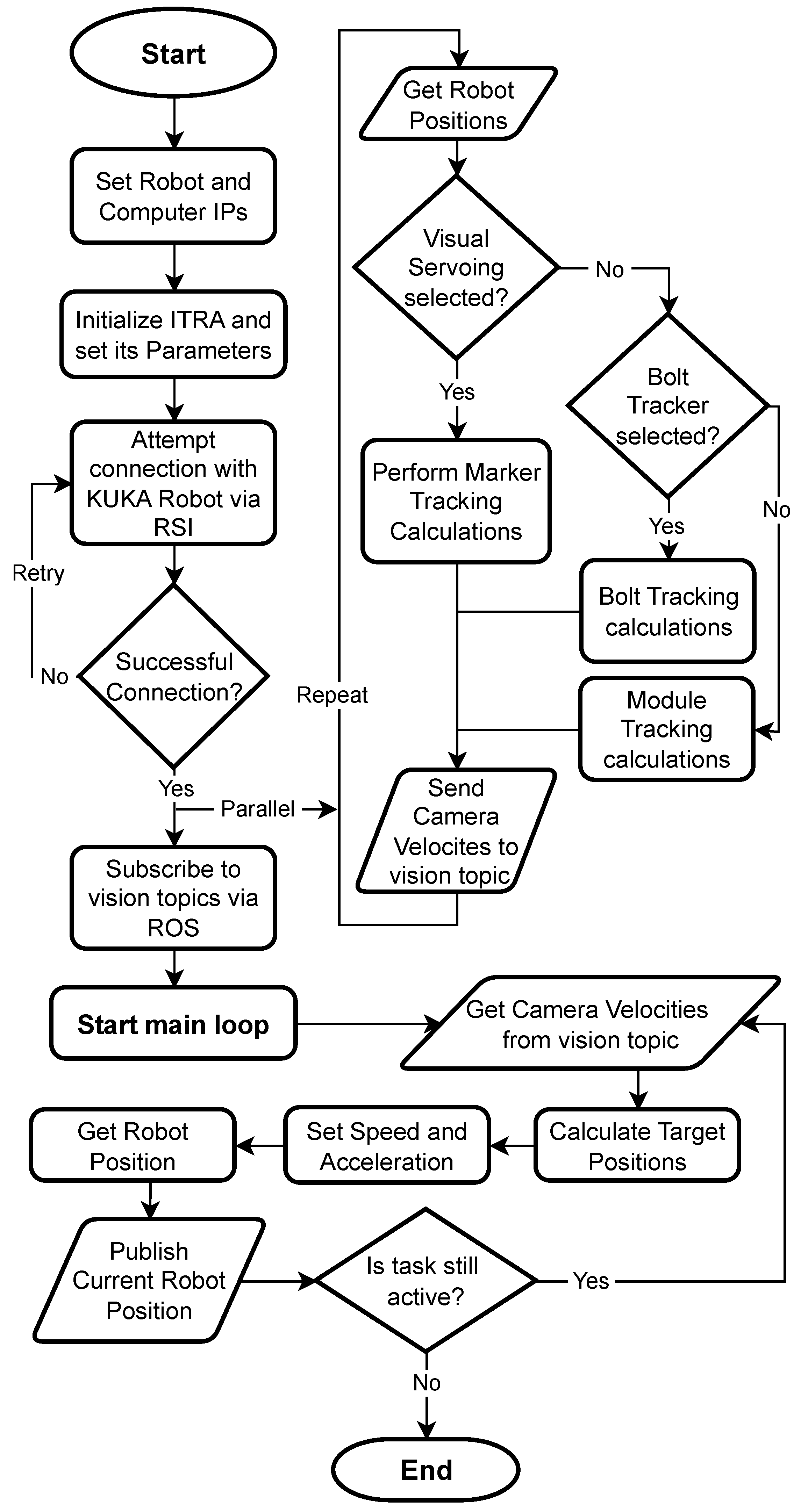
After converting into end-effector target positions, these are published into the robot at a rate of 250 Hz using ITRA, with this rate limitation imposed by the RSI Context in the KUKA controller. The trajectory execution is performed in real time, ensuring responsive and accurate robot movements in line with the visual servoing tasks. Figure 1 shows the communication process carried out for the robot control.
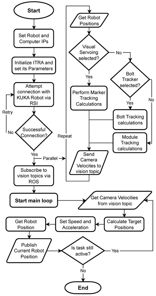
Figure 1.
Schematic flowchart of the Proposed Framework: integrated ITRA with DHVS. First routine connects to the robot via RSI and subscribes to camera and velocity topics, then calculates and publishes target speed and accelerations for the robot. In parallel image-based calculations for visual servoing, bolt tracking or module tracking are performed and published into camera and velocity topics.
3.2. Experimental Setup
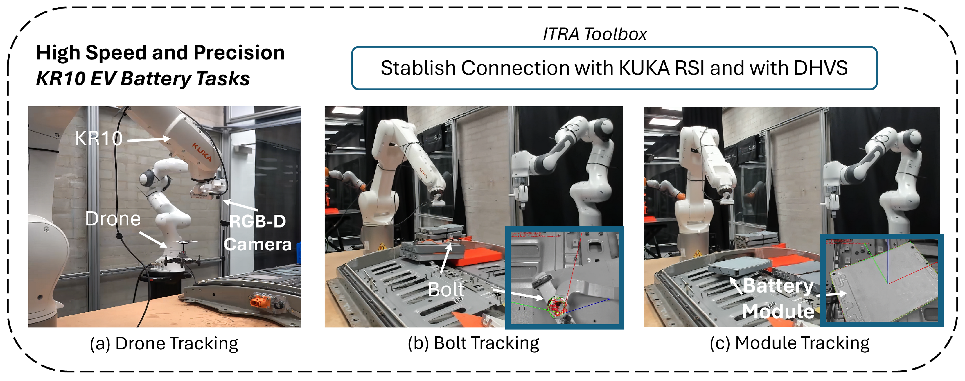
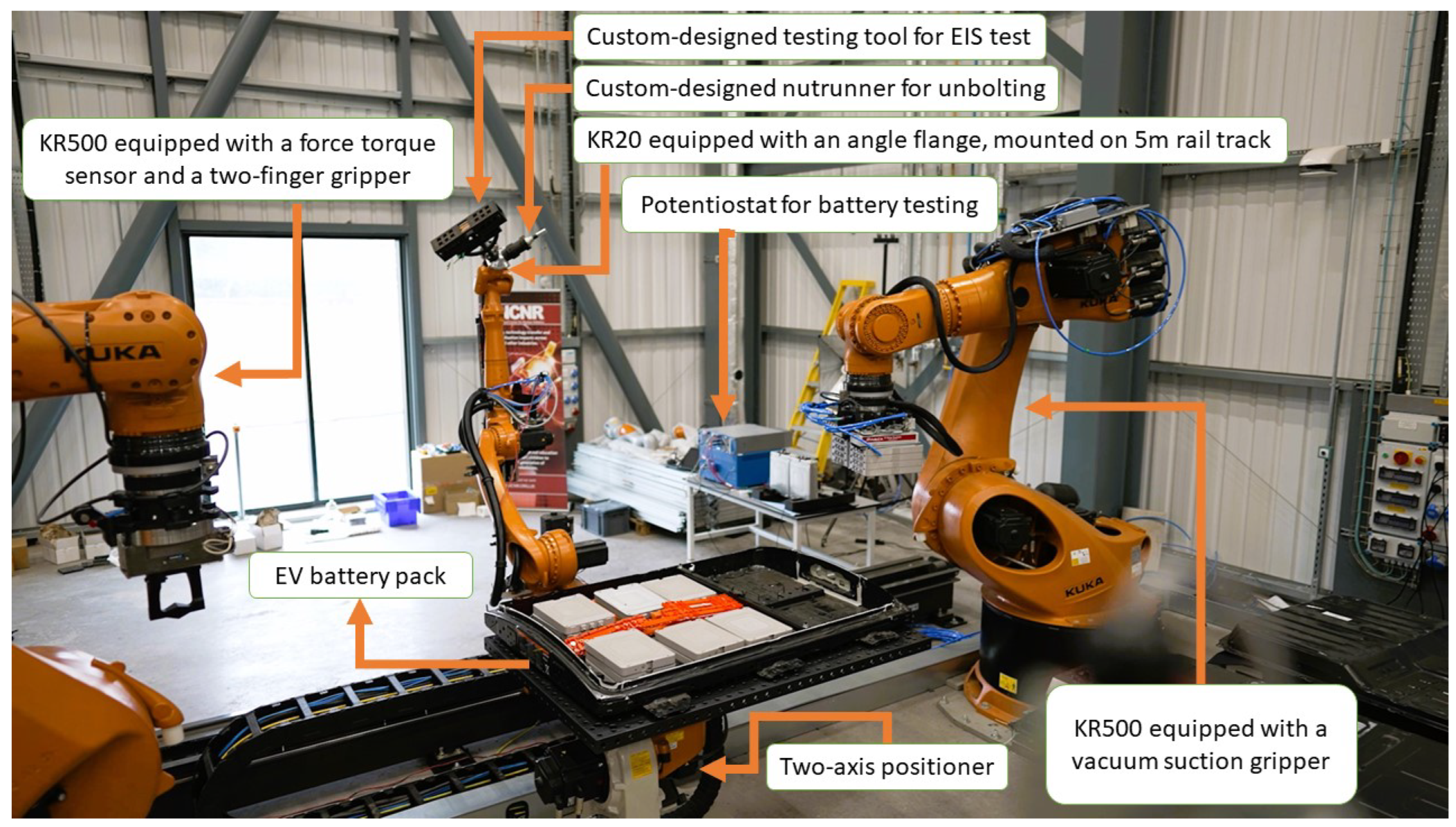
The testing setup is divided into two work cells: The first work cell comprises a KUKA KR10 with an RGB-D (Realsense 435i) camera mounted on the robot end-effector; this work cell is tested on high-speed and high-precision tasks, relying on marker and object tracking (Figure 2). The second work cell contains a KUKA KR500 with a Suction Gripper (VMECA V-Grip: Foam Pad) and an RGB-D (Realsense 435i) camera mounted on the end-effector (Figure 3). This latter space is set up to test heavy-duty applications in battery disassembly.
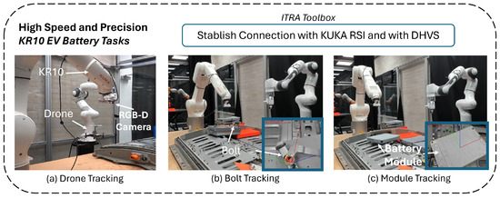
Figure 2.
The experimental setup for high speed and precision disassembly tasks using a KR10 KUKA robot arm. (a) Shows Rapid Marker Tracking with KR10. (b) Shows Bolt Detection and Tracking. (c) Shows Battery Module Detection and Tracking.
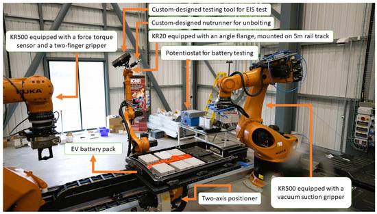
Figure 3.
The National Sustainable Robotic Centre including two heavy-duty KR500arms for lifting heavy objects like EV battery packs, a KR20 mounted on a 5 m rail track equipped with a nutrunner for unbolting, and a custom-design tool for testing battery modules by Electrochemical impedance spectroscopy. The National Sustainable Robotic Centre is located at the Birmingham Energy Innovation Centre in the Tyseley Energy Park.
Four distinct case studies have been meticulously designed to elucidate the effectiveness of the proposed framework in the intricate process of disassembling Nissan Leaf EV batteries, each deliberately crafted to spotlight a unique facet of the framework, such as its efficiency, communication speed, and accuracy. This strategic approach ensures a comprehensive evaluation of the framework’s overall efficacy. Complementing these case studies, the application of the proposed framework was further validated through a practical demonstration at the National Sustainable Robotic Centre (NSRC). Here, the initial step involved the removal of the top case of the EV battery pack, followed by the precise localization and subsequent removal of the battery stack of modules, thereby reinforcing the framework’s utility in streamlining the disassembly process of EV batteries.
ITRA was loaded into MATLAB 2023b (64-bit version) for all case studies, running within a computer with an Intel i7 CPU and 64 GB of RAM and equipped with an RTX 4080. The computer was linked to the controller of one KUKA KR500 robot or KUKA KR10, respectively, running a KUKA Robot Language (KRL) module and an RSI context that contained all required lines to enable the execution of the ITRA functions. A second computer was used to run the visual servoing control featuring a GTX 1080 Ti graphics card, an Intel i7 processor, and 32 GB of RAM. It is important to note that ITRA can work with other programming languages such as Python and C++, as it is a group of binaries that was compiled in Linux, and that Matlab is only utilized because of its ease of use. Although for this application it is running on Windows, ITRA can be used across different operating systems including the Real Time Linux Kernels; also, we note that the RSI context, which is needed for the communication, runs within a real-time platform in the robot controller; hence, the claim of real-time behaviour.
3.3. Visual Servoing Calibration
Before conducting the experiments, hand-eye calibration was performed for KR500 and KR10 robots using the Visual Servoing Platform (ViSP) [31]. This allowed the coordinate systems of each robot to align with those of their respective vision cameras. The calibration process involved using a standard chessboard marker as a reference object. The camera was positioned in 30 distinct joint configurations for each robot, capturing the chessboard from various angles and distances in a half-sphere motion around the chessboard. The data collected from these varied positions were processed using ViSP’s “hand2eye” calibration algorithm [32]. This procedure computed the transformation matrices between the cameras and the robot arms, synchronizing the visual and physical coordinate systems.
4. Experiments
The case studies are designed to evaluate the capabilities of ITRA in industrial robots enhanced with visual servoing, specifically focusing on tasks related to Electric Vehicle (EV) battery disassembly. The integrated framework underwent testing on the KR500 to assess its applicability in applications and tasks demanding higher industrial power. Conversely, it was evaluated on the KR10 for tasks requiring fine control.
4.1. Case 1: Rapid Marker Tracking with KR10
The first task features the KR10 robot, equipped with an RGB-D Camera. This study focuses on fast-paced, dynamic object tracking, where the KR10 is tasked with following a flying drone marked with a visual identifier as shown in Figure 2a. Testing capabilities to quickly adapt to moving targets, showcasing the high communication rate of ITRA and the accuracy of the DHVS in the dynamic environment. During battery disassembly, the positions of the components change continuously, requiring the vision system to track the locations of the objects without interruption.
4.2. Case 2: Bolt Detection and Tracking
In this scenario, the KR10 accurately tracks a bolt, as illustrated in Figure 2b, emphasizing precise alignment with the bolt’s position with a slight, intentional offset—a common requirement in EV battery disassembly workflows. This task demonstrates the precision and finesse of the DHVS system, coupled with ITRA, particularly in managing smaller and more delicate objects.
4.3. Case 3: Battery Module Detection and Tracking
The third case study involved the KR10 tracking a large battery module. The robot efficiently follows the module throughout the scene, guided by the physical model of the battery module as shown in Figure 2c. This exploits DHVS’s versatility in tracking and managing larger objects that can be part of any disassembly process.
4.4. Case 4: Case and Packs Sorting with DHVS
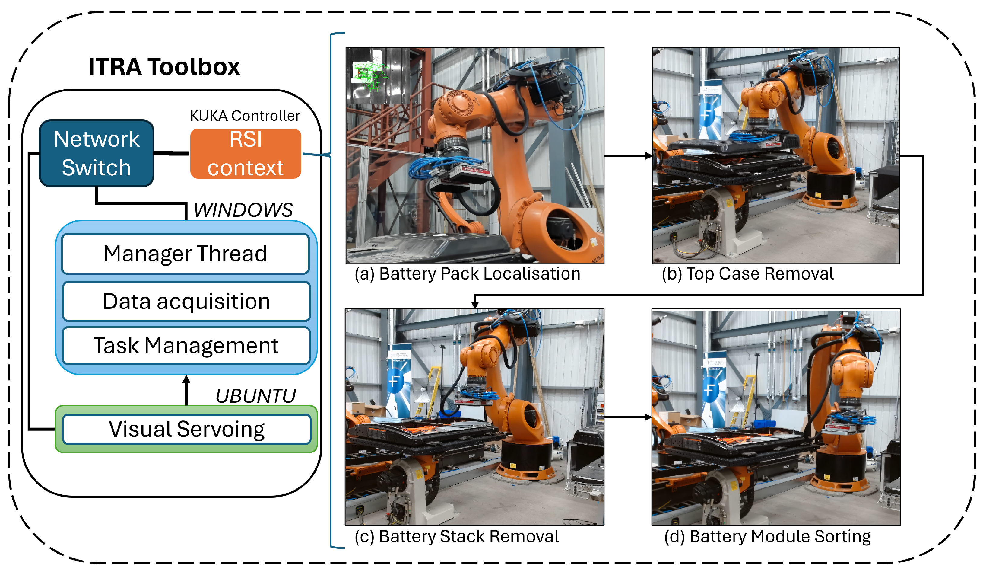
In the final case study, we deploy the KR500 robot, equipped with a vacuum suction gripper and an RGB-D camera, as depicted in Figure 4. This setup utilizes the DHVS to track markers affixed to the battery case and the battery packs, facilitating their localization and subsequent sorting into the disassembly area. Initially, visual servoing guides the robot’s end-effector to approach the battery case closely. Following this, the top case is detached and conveyed to the sorting area. The process of visual servoing is then repeated for the battery packs, which are sorted utilizing the vacuum gripper. After accurately tracking the object, the robot approaches the object’s location with a predefined offset from the marker. This case study is designed to demonstrate the robustness and precision of DHVS in complex, real-world battery disassembly tasks that require a higher force to operate.
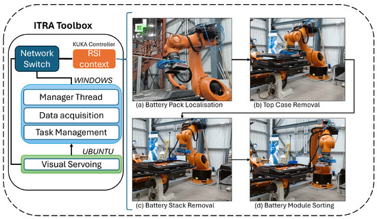
Figure 4.
Outline of the proposed framework deployed at the robotic test bed at NSRC. The framework utilising the ITRA toolbox connects to the KUKA KR500 Industrial robot via a digital RSI Context, and a physical network switch, where Ubuntu performs visual servoing from data obtained from a camera, and that is transferred to window where data processing and robot commands are determined and uploaded to the robot. (a,b) show the process of the Top Case Removal, consisting of the localization of the case, and its sorting. (c,d) show the process of sorting a battery stack, which consists of localization and sorting.
The precision of the DHVS system is vital for each case study, with the system allowing a 5% error in distance to the centre of the markers and objects in each task, with a reduction in this threshold allowed to permit a more precise but slower disassembly, which was not needed due to the nature of the tasks. The system can work on models that vary by size and position as long as they have the same shape, and can be expanded to other objects, if a model file is created for them, or contain a marker.
5. Results and Discussion
5.1. Integrated ITRA-DHVS for EV Battery Disassembly Using KR500 Robot Arm
The disassembly process at the NSRC was segmented into two primary tasks: Top Case Sorting and Battery Stack Sorting. Each task was timed and monitored for communication and camera rates, with the results summarized in Table 1. These findings illustrate the efficiency of the integrated system in performing tasks within the battery disassembly process. It is important to note that these times were obtained in T1 (Manual Reduced Velocity) mode, limiting the robot’s speed to 10% of its maximum; improvements in time are achievable in fully automatic mode. The Top Case Sorting was subdivided into two sub-tasks: Localization and Removal, averaging 27 and 39 s, respectively. Similarly, Battery Stack Sorting was divided into Stack Localization and Module Sorting, lasting an average of 32 s and 24 s, respectively. Across all tasks, the framework maintained an average communication rate of 250 Hz and a camera rate of 60 Hz. Assumptions were made, such as the prior removal of connectors, cables, and other battery components, because this disassembly scenario was primarily focused on testing the capabilities of the ITRA framework as a foundation for future work. Future investigations will include more components throughout the scene to offer a more accurate representation of the battery disassembly process, with an anticipated speed increase of up to 50% of the industrial robot’s maximum speed. With the current speed, the total removal of 48 battery cells is expected to take approximately 22 min, as the robot can remove two stacks per trip, requiring at least 24 trips. If the battery disassembly speed were increased to 50% or five times its current rate, the completion time is expected to be approximately 4 min. Other disassembly scenarios can be conducted using the same methodology, relying on the ITRA framework. A primary challenge in this case study was selecting the offsets for contact with the battery components. Future work will explore incorporating force sensors and mixed teleoperated control, allowing the operator to intervene at the moment of contact, thereby facilitating these tasks.

Table 1.
Battery disassembly.
5.2. Integrated ITRA-DHVS for EV Battery Disassembly Using KR10 Robot Arm
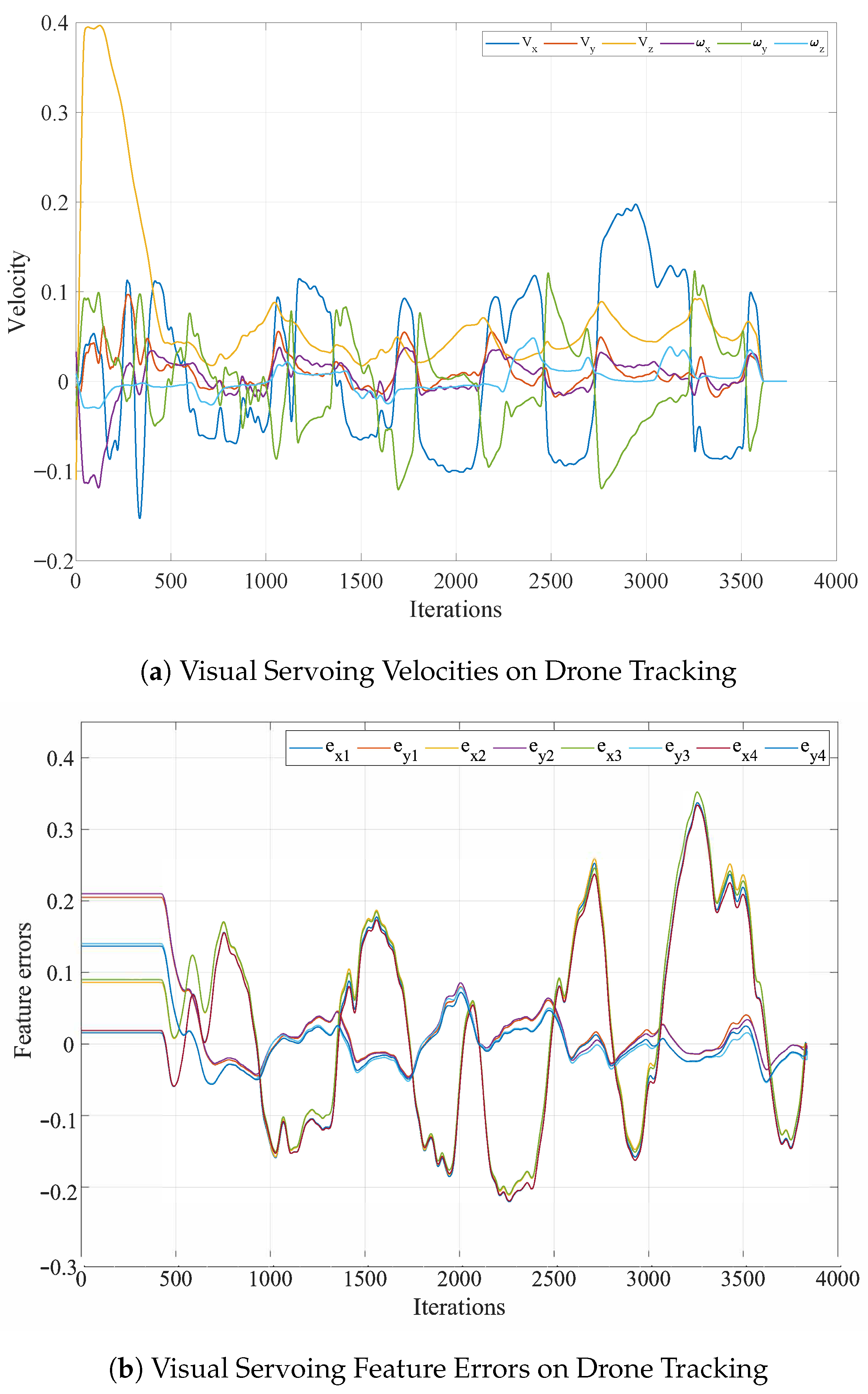
In the task of visual servoing for rapid movements and drone tracking, the KR10 robot exhibited its capability to adeptly adjust to swift alterations in the drone’s position, consistently following it. This process required approximately 500 iterations, with each iteration lasting 4 ms, to accurately align with the drone’s position, as illustrated in Figure 5a,b. Despite the limitations imposed by the camera’s refresh rate on capturing the drone’s position, ITRA’s consistent communication rate ensured effective control over the robot during these rapid movement tasks.
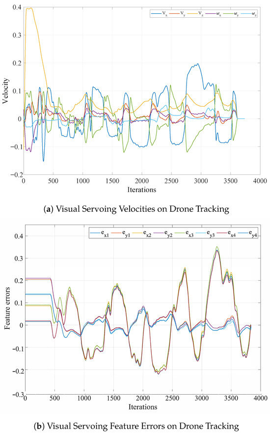
Figure 5.
Real-world results of DHVS for drone tracking. (a) Visual Servoing Velocities while tracking fast movement drone. (b) Feature errors and visual servoing for fast movement drone.
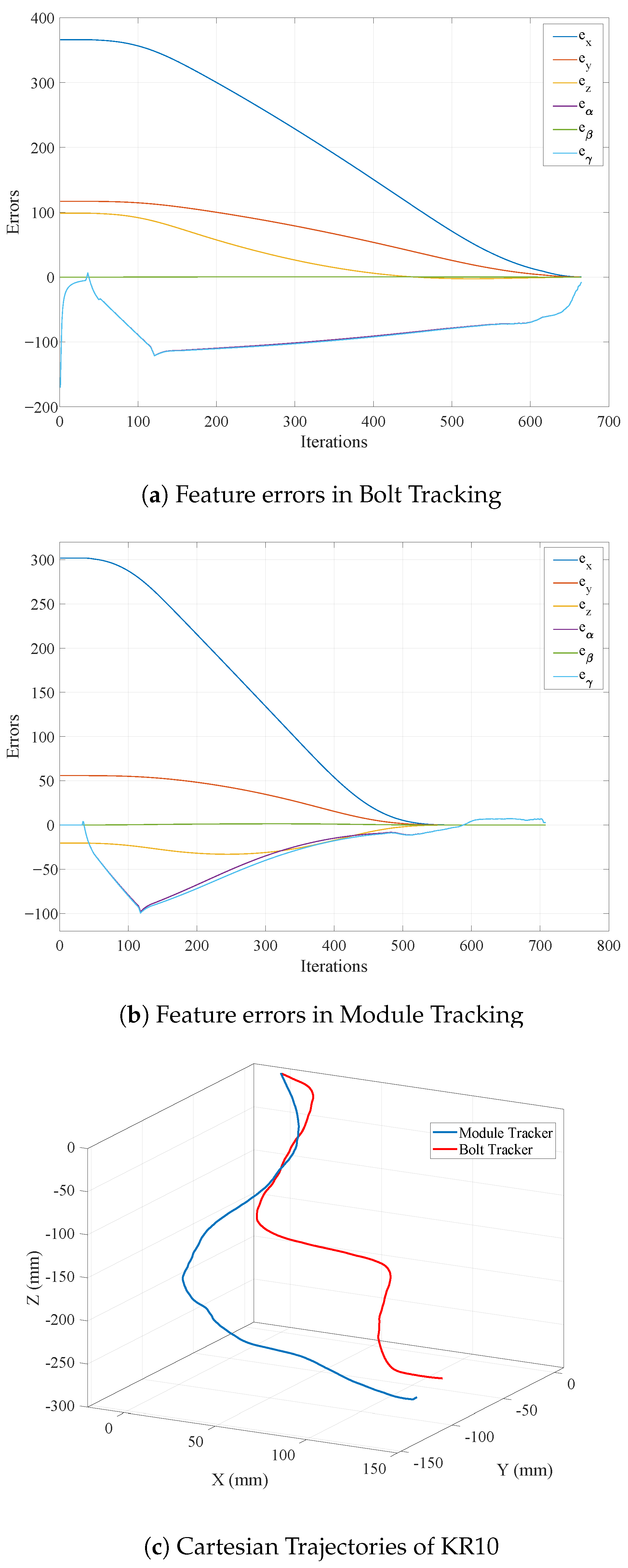
In the Bolt tracking task, the KR10 significantly minimized the error rate, achieving positional repeatability nearly at the manufacturer’s specified level. It successfully converged in on the bolt’s position in less than 700 iterations on average, as depicted in Figure 6a. For the battery module tracking task, the number of iterations required varied between 550 and 700, as demonstrated in Figure 6b.
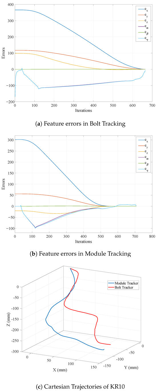
Figure 6.
Real-world results for object tracking cases: (a) Feature errors with DHVS in bolt tracking, (b) Feature errors with DHVS in module tracking, (c) Cartesian trajectory of KR10 performing bolt tracking task in red, and Cartesian trajectory of KR10 performing battery module tracking task in blue.
Typical Cartesian trajectories for both object-tracking tasks are shown in Figure 6c. It is important to note that the divergence between case studies in the KR10 with the KR500 reflects their suitability for different scales of tasks. KR10 being a small industrial robot is suited for handling delicate and dynamically changing tasks. While KR500 with its strength is good for large-scale and high power demanding tasks, although it is also capable of precise and delicate handling. Primary difficulties in scaling from the KR10 implementation to the KR500 implementation are related to the calibration and accuracy. The bigger system is more susceptible to calibration errors, as it covers a bigger area, making it necessary to do a more precise alignment from the vision camera and reference object. A well-calibrated KR500 system should be able to perform equally precise tasks as the KR10 only limited to the size of the objects it can manage, and to the visibility of such objects, for this in future works, a more dedicated calibration procedure is recommended. with at least 40 different end-effector positions covering more positions.
The success of our battery disassembly tasks will enable us to extend our system to other domains, such as space and medical fields, while incorporating variable autonomy and mixed teleoperation control. In space exploration, the precision and adaptability of our system could prove crucial for tasks such as satellite repair and space debris management. Similarly, the demonstrated precision and control could significantly enhance surgical robotics in the medical field, facilitating minimally invasive procedures. With variable autonomy, the tracking capabilities provided by ITRA and DHVS in industrial robots could permit a seamless switch between object detection and manual control to complete more complex tasks. ITRA enhances this process with its precise control and high communication rate. Future efforts will be focused on adapting our methodologies to these sectors and further expanding the capabilities of ITRA by facilitating changes in autonomy and modes of operation.
6. Conclusions
This paper has shown the integration of visual tracking and servoing together with the Interfacing Toolbox for Robotic Arms (ITRA). Its applications were demonstrated in industrial settings related to the disassembly of Electriv Vehicle (EV) battieries. The integration has proven ITRA’s flexibility and capabilities, particularly those in control strategies, with this case enabling vision-guided control. This capability proves advantageous for transitioning from collaborative robots (cobots) programming, to the management of industrial robots, which tend to be pre-programmed. Moreover, ITRA’s advanced functionality has been shown to be both effective and efficient, facilitating its application across various systems employing different programming languages.
Real-time adaptive behaviour has significantly improved the capabilities of both the KR500 and KR10 robots in executing vision-guided manipulation tasks for EV battery disassembly. While ITRA facilitated control of the robot arm at rates up to 250 Hz, the reaction time of the vision system for acceleration calculations was limited by the camera’s refresh rate at the end-effector, at 60 fps, which was plenty at the limited velocity T1 (Manual Reduced Velocity) mode the KUKA controller allowed.
Performance was consistently upheld in industrial scenarios, achieving precision and efficiency in heavy-duty tasks, with Top Case removal of an EV battery pack within 66 s, and sorting battery modules accomplished in 56 s. Additionally, the system’s adaptability was demonstrated in dynamic environments, as shown by the KR10’s rapid convergence during tracking tasks, requiring only between 500–700 iterations. Current efforts and improvements to the system are being made on teleoperating the KUKA robot arm with various haptic systems and force feedback mechanisms. Future work aims to implement and enhance variable autonomy within these systems, facilitating transitioning between teleoperated control and autonomous vision-based movement, tailored to the specific requirements of task duration, precision, and variability.
Author Contributions
Conceptualization, A.R., C.M. and A.A.; Methodology, A.R., C.M. and A.A.; Software, C.M., C.A.C., A.A. and G.P.; Validation, C.M. and A.A.; Formal analysis, C.A.C. and A.A.; Resources, A.R. and R.S.; Data curation, G.P.; Writing—original draft, A.R., C.A.C. and A.A.; Writing—review & editing, A.R., C.M. and R.S.; Supervision, A.R. and R.S.; Project administration, A.R.; Funding acquisition, A.R. and R.S. All authors have read and agreed to the published version of the manuscript.
Funding
This work was supported in part by the UK Research and Innovation (UKRI) project “Reuse and Recycling of Lithium-Ion Batteries” (RELiB) under RELiB2 Grant FIRG005 and RELiB3 Grant FIRG057, by the project called “Research and Development of a Highly Automated and Safe Streamlined Process for Increase Lithium-ion Battery Repurposing and Recycling” (REBELION) under Grant 101104241 and by the project called “Mutual cross-contamination between automated non-destructive testing and adaptive robotics for extreme environments” under the Royal Society International Exchanges 2022 Cost Share Grant (IEC\R2 \222079).
Data Availability Statement
Data available in a publicly accessible repository; The Interfacing Toolbox for Robotic Arms (ITRA) compiled binaries are available at https://doi.org/10.15129/bfa28b77-1cc0-4bee-88c9-03e75eda83fd (accessed on 16 February 2024).
Conflicts of Interest
The authors declare no conflict of interest.
References
- Yang, G.Z.; Bellingham, J.; Dupont, P.E.; Fischer, P.; Floridi, L.; Full, R.; Jacobstein, N.; Kumar, V.; McNutt, M.; Merrifield, R.; et al. The grand challenges of Science Robotics. Sci. Robot. 2018, 3, eaar7650. [Google Scholar] [CrossRef] [PubMed]
- Tian, G.; Yuan, G.; Aleksandrov, A.; Zhang, T.; Li, Z.; Fathollahi-Fard, A.M.; Ivanov, M. Recycling of spent Lithium-ion Batteries: A comprehensive review for identification of main challenges and future research trends. Sustain. Energy Technol. Assessments 2022, 53, 102447. [Google Scholar] [CrossRef]
- Fitka, I.; Kralik, M.; Vachalek, J.; Vasek, P.; Rybar, J. A teaching tool for operation and programming industrial robots kuka. Slavon. Pedagog. Stud. J. 2019, 8, 314–321. [Google Scholar] [CrossRef]
- Mišković, D.; Milić, L.; Čilag, A.; Berisavljević, T.; Gottscheber, A.; Raković, M. Implementation of Robots Integration in Scaled Laboratory Environment for Factory Automation. Appl. Sci. 2022, 12, 1228. [Google Scholar] [CrossRef]
- Golz, J.; Wruetz, T.; Eickmann, D.; Biesenbach, R. RoBO-2L, a Matlab interface for extended offline programming of KUKA industrial robots. In Proceedings of the 2016 11th France-Japan and 9th Europe-Asia Congress on Mechatronics, MECATRONICS 2016/17th International Conference on Research and Education in Mechatronics, REM 2016, Compiegne, France, 15–17 June 2016; pp. 64–67. [Google Scholar] [CrossRef]
- Chinello, F.; Scheggi, S.; Morbidi, F.; Prattichizzo, D. KUKA control toolbox. IEEE Robot. Autom. Mag. 2011, 18, 69–79. [Google Scholar] [CrossRef]
- Servoing, V. Real Time Control of Robot Manipulators Based on Visual Sensory Feedback; World Scientific Series in Robotics and Automated Systems; World Scientific Pub Co., Inc.: Singapore, 1993; Volume 7. [Google Scholar]
- Mansard, N.; Chaumette, F. A new redundancy formalism for avoidance in visual servoing. In Proceedings of the 2005 IEEE/RSJ International Conference on Intelligent Robots and Systems, Edmonton, AB, Canada, 2–6 August 2005; IEEE: Piscataway, NJ, USA, 2005; pp. 468–474. [Google Scholar]
- Rastegarpanah, A.; Ahmeid, M.; Marturi, N.; Attidekou, P.S.; Musbahu, M.; Ner, R.; Lambert, S.; Stolkin, R. Towards robotizing the processes of testing lithium-ion batteries. Proc. Inst. Mech. Eng. Part I J. Syst. Control Eng. 2021, 235, 1309–1325. [Google Scholar] [CrossRef]
- Paolillo, A.; Chappellet, K.; Bolotnikova, A.; Kheddar, A.; Interlinked, A.K.; Chappellet, K. Interlinked visual tracking and robotic manipulation of articulated objects. IEEE Robot. Autom. Lett. 2018, 3, 2746–2753. [Google Scholar] [CrossRef]
- Mineo, C.; Wong, C.; Vasilev, M.; Cowan, B.; MacLeod, C.N.; Pierce, S.G.; Yang, E. Interfacing Toolbox for Robotic Arms with Real-Time Adaptive Behavior Capabilities; University of Strathclyde: Glasgow, UK, 2019. [Google Scholar] [CrossRef]
- Rastegarpanah, A.; Aflakian, A.; Stolkin, R. Improving the Manipulability of a Redundant Arm Using Decoupled Hybrid Visual Servoing. Appl. Sci. 2021, 11, 11566. [Google Scholar] [CrossRef]
- Zhang, Y.; Zhang, H.; Wang, Z.; Zhang, S.; Li, H.; Chen, M. Development of an Autonomous, Explainable, Robust Robotic System for Electric Vehicle Battery Disassembly. In Proceedings of the IEEE/ASME International Conference on Advanced Intelligent Mechatronics, AIM, Seattle, WA, USA, 28–30 June 2023; pp. 409–414. [Google Scholar] [CrossRef]
- Xiao, J.; Gao, J.; Anwer, N.; Eynard, B. Multi-Agent Reinforcement Learning Method for Disassembly Sequential Task Optimization Based on Human-Robot Collaborative Disassembly in Electric Vehicle Battery Recycling. J. Manuf. Sci. Eng. 2023, 145, 121001. [Google Scholar] [CrossRef]
- Gerlitz, E.; Enslin, L.E.; Fleischer, J. Computer vision application for industrial Li-ion battery module disassembly. Prod. Eng. 2023, 1, 1–9. [Google Scholar] [CrossRef]
- Hathaway, J.; Shaarawy, A.; Akdeniz, C.; Aflakian, A.; Stolkin, R.; Rastegarpanah, A. Towards reuse and recycling of lithium-ion batteries: Tele-robotics for disassembly of electric vehicle batteries. Front. Robot. AI 2023, 10, 1179296. [Google Scholar] [CrossRef] [PubMed]
- Namazov, M. Fuzzy Logic Control Design for 2-Link Robot Manipulator in MATLAB/Simulink via Robotics Toolbox. In Proceedings of the 2018 Global Smart Industry Conference, GloSIC 2018, Chelyabinsk, Russia, 13–15 November 2018. [Google Scholar] [CrossRef]
- Bien, D.X.; My, C.A.; Khoi, P.B. Dynamic analysis of two-link flexible manipulator considering the link length ratio and the payload. Vietnam J. Mech. 2017, 39, 303–313. [Google Scholar] [CrossRef][Green Version]
- Mariottini, G.L.; Alunno, E.; Prattichizzo, D. The Epipolar Geometry Toolbox (EGT) for Matlab; University of Siena: Siena, Tuscany, 2004; Available online: http://egt.dii.unisi.it/ (accessed on 20 January 2024).
- Corke, P. Robotics and Control: Fundamental Algorithms in MATLAB®; Springer Nature: Berlin/Heidelberg, Germany, 2021; Volume 141. [Google Scholar]
- Safeea, M.; Neto, P. KUKA Sunrise Toolbox: Interfacing Collaborative Robots with MATLAB. IEEE Robot. Autom. Mag. 2019, 26, 91–96. [Google Scholar] [CrossRef]
- Mokaram, S.; Aitken, J.M.; Martinez-Hernandez, U.; Eimontaite, I.; Cameron, D.; Rolph, J.; Gwilt, I.; McAree, O.; Law, J. A ROS-integrated API for the KUKA LBR iiwa collaborative robot. IFAC-PapersOnLine 2017, 50, 15859–15864. [Google Scholar] [CrossRef]
- Corke, P.; Haviland, J. Not your grandmother’s toolbox - the Robotics Toolbox reinvented for Python. In Proceedings of the IEEE International Conference on Robotics and Automation, Xi’an, China, 30 May–5 June 2021; pp. 11357–11363. [Google Scholar] [CrossRef]
- Mineo, C.; Vasilev, M.; Cowan, B.; MacLeod, C.; Pierce, S.G.; Wong, C.; Yang, E.; Fuentes, R.; Cross, E. Enabling robotic adaptive behaviour capabilities for new industry 4.0 automated quality inspection paradigms. Insight-Non Test. Cond. Monit. 2020, 62, 338–344. [Google Scholar] [CrossRef]
- Mineo, C.; Cerniglia, D.; Poole, A. Autonomous robotic sensing for simultaneous geometric and volumetric inspection of free-form parts. J. Intell. Robot. Syst. 2022, 105, 54. [Google Scholar] [CrossRef]
- Albeladi, A.; Ripperger, E.; Hutchinson, S.; Krishnan, G. Hybrid Eye-in-Hand/Eye-to-Hand Image Based Visual Servoing for Soft Continuum Arms. IEEE Robot. Autom. Lett. 2022, 7, 11298–11305. [Google Scholar] [CrossRef]
- Taylor, G.; Kleeman, L. Hybrid position-based visual servoing with online calibration for a humanoid robot. In Proceedings of the 2004 IEEE/RSJ International Conference on Intelligent Robots and Systems (IROS), Sendai, Japan, 28 September–2 October 2004; Volume 1, pp. 686–691. [Google Scholar] [CrossRef]
- Raja, R.; Kumar, S. A Hybrid Image Based Visual Servoing for a Manipulator using Kinect. In Proceedings of the ACM International Conference Proceeding Series, New York, NY, USA, 28 June–2 July 2017. Part F132085. [Google Scholar] [CrossRef]
- Ye, G.; Li, W.; Wan, H.; Lou, H.; Lu, Z.; Zheng, S. Image based visual servoing from hybrid projected features. In Proceedings of the IEEE Region 10 Annual International Conference, Proceedings/TENCON, Macao, China, 1–4 November 2015; pp. 1–6. [Google Scholar] [CrossRef]
- Mekonnen, G.; Kumar, S.; Pathak, P.M. Wireless hybrid visual servoing of omnidirectional wheeled mobile robots. Robot. Auton. Syst. 2016, 75, 450–462. [Google Scholar] [CrossRef]
- Marchand, É.; Spindler, F.; Chaumette, F. ViSP for visual servoing: A generic software platform with a wide class of robot control skills. IEEE Robot. Autom. Mag. 2005, 12, 40–52. [Google Scholar] [CrossRef]
- visp. hand2eye. Calibration Package. A Camera Position with Respect to Its Effector Is Estimated by visp_hand2eye_calibration Using the ViSP Library. Available online: https://wiki.ros.org/visp_hand2eye_calibration (accessed on 16 February 2024).
Disclaimer/Publisher’s Note: The statements, opinions and data contained in all publications are solely those of the individual author(s) and contributor(s) and not of MDPI and/or the editor(s). MDPI and/or the editor(s) disclaim responsibility for any injury to people or property resulting from any ideas, methods, instructions or products referred to in the content. |
© 2024 by the authors. Licensee MDPI, Basel, Switzerland. This article is an open access article distributed under the terms and conditions of the Creative Commons Attribution (CC BY) license (https://creativecommons.org/licenses/by/4.0/).

