Article

A Low-Cost and High-Efficiency Active Cell-Balancing Circuit for the Reuse of EV Batteries

1
Institute of Mechatronics, Changwon National University, Changwon 51140, Republic of Korea
2
Department of Electrical Engineering, Changwon National University, Changwon 51140, Republic of Korea
*
Author to whom correspondence should be addressed.
Batteries 2024, 10(2), 61; https://doi.org/10.3390/batteries10020061
Submission received: 7 December 2023 / Revised: 30 January 2024 / Accepted: 13 February 2024 / Published: 15 February 2024
(This article belongs to the Section Battery Modelling, Simulation, Management and Application)

Abstract

:
In this paper, a high-efficiency and low-cost active cell-to-cell balancing circuit for the reuse of electric vehicle (EV) batteries is proposed. In the proposed method, a battery string is divided into two legs to transfer the charge from each cell in one leg to that in the other and a bidirectional CLLC resonant converter is used to transfer energy between the selected cells. Thanks to the proposed structure, the number of bidirectional switches and gate drivers can be reduced by half compared to the conventional direct cell-to-cell topologies, thereby achieving lower cost for the system. The CLLC converter is used to transfer the charge, and it is designed to work at resonant frequencies to achieve zero-voltage zero-current switching (ZVZCS) for all the switches and diodes. Consequently, the system’s efficiency can be enhanced, and hence, the fuel economy of the system can also be improved significantly. To verify the performance of the proposed active cell-balancing system, a prototype is implemented for balancing the three EV battery modules that contain twelve lithium-ion batteries from xEV. The maximum efficiency achieved for the charge transfer is 89.4%, and the balancing efficiency is 96.3%.

1. Introduction

The growth of electric vehicles (EVs) has witnessed a remarkable surge in recent years, transforming the automotive landscape and signaling a shift towards sustainable transportation. Technological advancements, coupled with increasing environmental awareness, have fueled the adoption of EVs as viable alternatives to traditional internal combustion engine vehicles. Governments around the world have implemented incentives and regulations to encourage the production and purchase of electric vehicles, contributing to the expansion of charging infrastructure. Major automakers are investing heavily in research and development to enhance battery efficiency, increase driving range, and reduce costs, making EVs more accessible to a broader consumer base. With the ongoing commitment to reduce carbon emissions and the global push towards a greener future, the growth of electric vehicles continues to accelerate, revolutionizing the way we perceive and experience personal transportation. It is reported that EVs have gained significant growth in sales in the period of 2016~2023 and are expected to continue to increase in 2024. If electric vehicles keep gaining ground in the automotive market at the exceptional rate recently witnessed, CO2 emissions from cars can be put on a path aligned with achieving net zero emissions by 2050 [1,2,3].
Among several types of power batteries, such as Pb–acid, Ni-MH, Ni-Cd, and Li-ion batteries; graphene-based batteries; and all-solid-state batteries, the Li-ion batteries provide superior performance in terms of energy efficiency and cycle times. Lithium iron phosphate (LFP) and nickel manganese cobalt (NMC) are two popular Li-ion battery types used in EVs. Compared to LFP batteries, NMC Li-ion batteries typically have a higher energy density, which enables them to provide more power and have a wider range of applications. Nevertheless, the NMC Li-ion batteries are more expensive and have a shorter cycle life [4].
A Li-ion-based EV battery typically comprises the following modules: a cooling system, battery management system (BMS), high-voltage wiring harness, frame construction, battery module, and others. An EV battery module/pack contains many cells. Cells can be connected in series to increase voltage and in parallel to increase capacity. The combination of series and parallel connections allows manufacturers to tailor the battery pack to meet specific performance. The BMS, which works in conjunction with batteries, has the ability to estimate battery state, balance cells, manage temperature, and diagnose faults. A well-designed BMS not only ensures the safe operation of the battery pack but also balances the cells as fast as possible [5,6,7].
However, an EV battery’s performance will decline after eight to ten years of use. Several factors that contribute to the degradation of batteries are cycling degradation, temperature effects, depth of discharge (DoD), over-charging and over-discharging, high and low state of charge (SOC), chemical reactions and side reactions, mechanical stresses, and so on [8]. The common definition of a battery’s first end of life is when the battery’s state of health (SoH) in terms of energy capacity or power capacity reaches 70–80%. The fast increase in EVs in the market will translate into an increase in waste batteries after their use in EVs. So, the decision currently facing us is whether to reuse electric vehicle batteries or to recycle them after their initial use [9]. Using vehicle data to verify the SoH and lack of defective cells in modules/packs is vital before redeploying them for second-life purposes. The battery pack has been disassembled to the module level. The individual modules are now undergoing testing, which will reveal the differences in deterioration and SoH across modules from the same pack. This testing of the retired batteries will also verify they meet the end-of-life performance characteristics required for reuse in other applications [10].
The reuse of EV battery systems for renewable energy introduction to an island power grid was introduced in [11]. In [12], a retired EV batter-forming ESS was proposed for load peak shifting in a grid. In practice, there are two common application scenarios for reusing retired EV batteries: static energy storage stations and dynamic mobile charging applications. A common static scenario is utilizing retired EV batteries for stationary energy storage purposes such as charging stations, communication base stations, etc. Typically, dynamic recycling utilization can be applied in mobile charging cars, low-speed electric vehicles (EVs), and other scenarios that demand lower performance.
When considering retired EV batteries for reuse, it is vital to examine the internal characteristics of battery cells from the same production batch, including their capacity, SOC, self-discharge rate, and internal resistance. Numerous studies have been conducted in this field. The state-of-the-art battery pack SOC estimation methods along with the impact of cell inconsistency on pack performance and SOC estimation are discussed in [7]. The technical and economic viability of retired EV battery repurposing to solve the unreliability of cleaner energy technologies and to mitigate the high investment of new storage systems was presented in [13,14].
Naturally, the voltage differences among the cells become larger as the batteries age; hence, the cell-balancing function is more demanding in the case of old batteries in their second life than brand new ones. Therefore, the cell-balancing function in a BMS can be regarded as an essential function since the imbalance in charges for a series of connected cells results in the battery’s usable capacity decreasing. In addition, it may eventually result in the early cell degradation and hence premature failure of the battery system since the imbalance tends to grow over time, and it is serious in the case of a second-life battery due to their unstable status [15].
To cope with the problem mentioned above, many different kinds of cell-balancing methods have been introduced [16]. The passive-cell-balancing and battery-charge-control-with-CCCV (constant current constant voltage) topology for Li-ion battery cells was introduced in [17]. The BMS cell-monitoring and protection design and test for LFP battery cells was described in [5]. The BMS cell-monitoring function has effectively shown the existence of imbalanced cell voltages during both charging and discharging processes. A BMS with high current balancing was presented in [18]. An active cell balancing circuit based on a forward DC–DC converter for series-connected battery cells was proposed in [19]. A single non-isolated DC/DC converter and controlled switches-based active balancing topology was proposed in [20]. A low-voltage-to-cell (LV2C) balancing architecture for electric vehicle batteries that uses a low-voltage battery as a convenient source and sink for balancing was presented in [21].
It can be divided into two categories: passive methods and active methods [22,23]. The passive method is popularly employed due to its lower cost, but it is inefficient in terms of energy saving and the speed of balancing since energy is wasted in the form of heat and the balancing current is typically small. The active cell-balancing methods can be classified into several kinds such as cell-to-pack (C2P), pack-to-cell (P2C), cell-to-pack-to-cell (C2P2C), adjacent cell-to-cell (AC2C), and direct cell-to-cell (DC2C) [24]. The C2P method is the worst in terms of performance when one cell has less voltage and all the others are balanced. In contrast, P2C becomes worse when one cell has a higher voltage while all the others are balanced. Though C2P2C is a combination of the C2P and P2C methods that solve the problems mentioned above, it is expensive and complex in terms of control. The AC2C method requires many cycles to transfer the charge from a cell to an adjacent cell, thereby causing more losses and a slower balancing process. With the DC2C method, the charge can be directly transferred from any high-voltage cell to any low-voltage cell. Consequently, a higher efficiency and a higher balancing speed can be achieved even in high-power applications. However, in the conventional DC2C topologies introduced in [23,24,25], four bidirectional switches in the selection network are required to connect one cell with both the input and output of the converter to charge or discharge the selected cell. As a result, the DC2C method is high in cost due to the large number of switches and gate drivers.
This research presents a low-cost and high-efficiency active cell-to-cell balancing circuit for the reuse of an EV battery. In the proposed circuit, the DC2C balancing method is used to achieve high efficiency and fast balancing. In the proposed topology, all of the battery cells connected in series are divided into two legs and all of the cells in one leg are connected to the input and output of the bidirectional CLLC converter, respectively. In the proposed balancing topology, two bidirectional switches are used to select a cell and two adjacent cells can share one bidirectional switch. Hence, the number of switches and gate drivers required for the selection network can be reduced by half compared to that of the conventional DC2C topologies. Moreover, switches with low voltage ratings and a gate driver with low-frequency operation can be employed; hence, the cost of the system can be further reduced.
This paper consists of five sections. Section 2 outlines the structure, operating principles, and characteristics of the proposed method. Section 3 presents the experimental results of a prototype for the proposed balancing circuit. Section 4 details the performance analysis of the proposed method. The conclusions are presented in Section 5.

2. Proposed Direct Cell-to-Cell Balancing Method

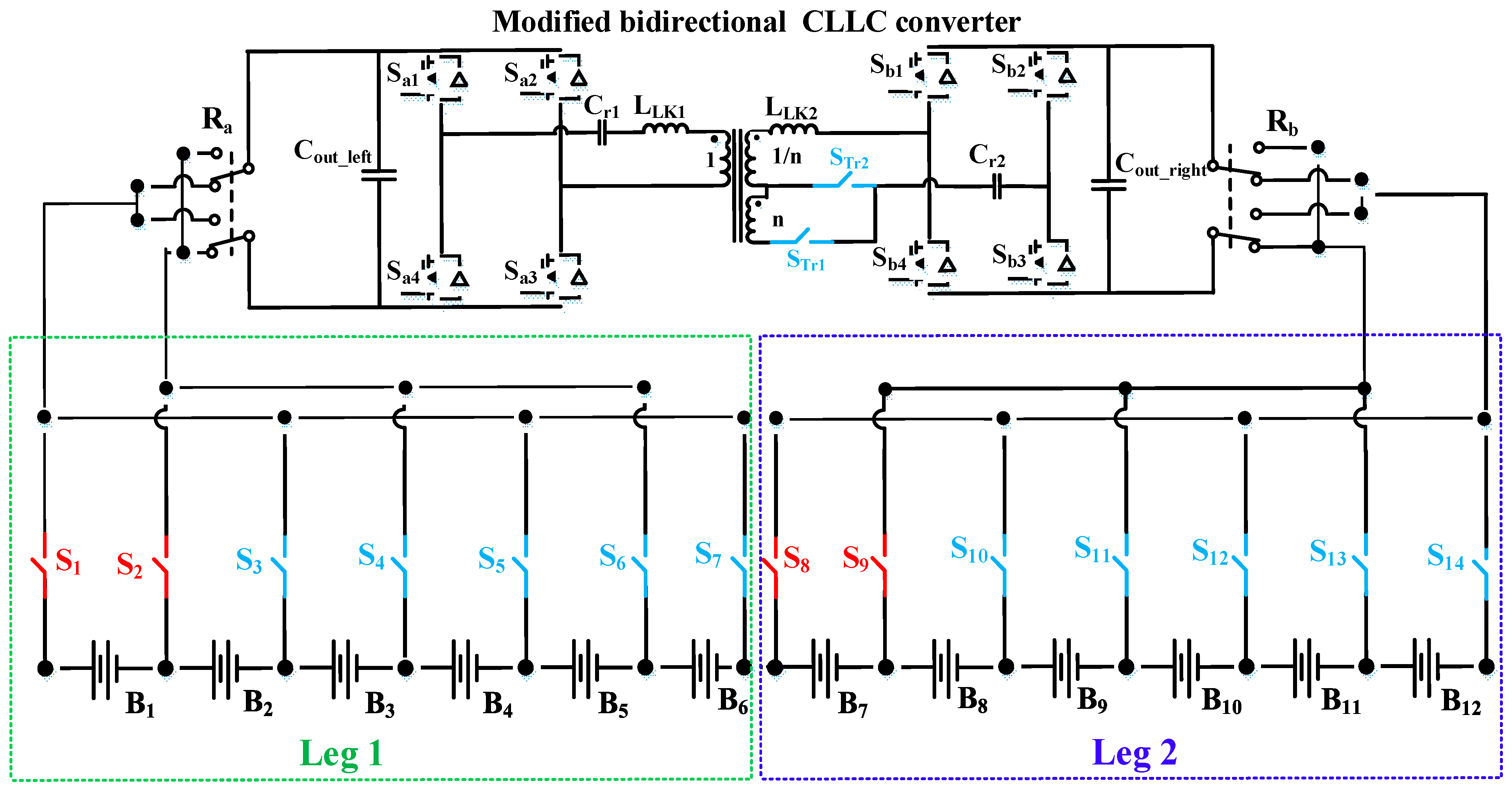
2.1. Structure of the Proposed Balancing Technology

Figure 1 shows the structure of the proposed direct cell-to-cell balancing topology. It is composed of a selection network to select two target cells for the balancing, and the three-port CLLC converter is used as a charge carrier. The battery string is divided into two legs, and two bidirectional switches are required to connect a battery cell to the input and the output of the CLLC converter, respectively. The switch between two adjacent cells can be shared so that only N + 2 selection switches are required in the selection network, where N is the number of cells. Bidirectional MOSFETs are used as selection switches to prevent a short circuit between cells. Since the power required for driving the gate drivers of the MOSFETs is supplied by the battery cells, no external power supply is required for the selection network, as shown in Figure 2. P-channel MOSFET switches are used for two cells on top of each leg (S1, S2, S8, and S9) due to the negative voltage required to operate those switches, and N-channel MOSFETs are used for the others. The three-pole switches Ra and Rb are used to make sure the right polarity of battery cells is connected to the converter. It should be noted that the switches with low voltage ratings and the gate drivers with low-frequency operation can be used due to the inherent nature of the cell-to-cell balancing circuit.

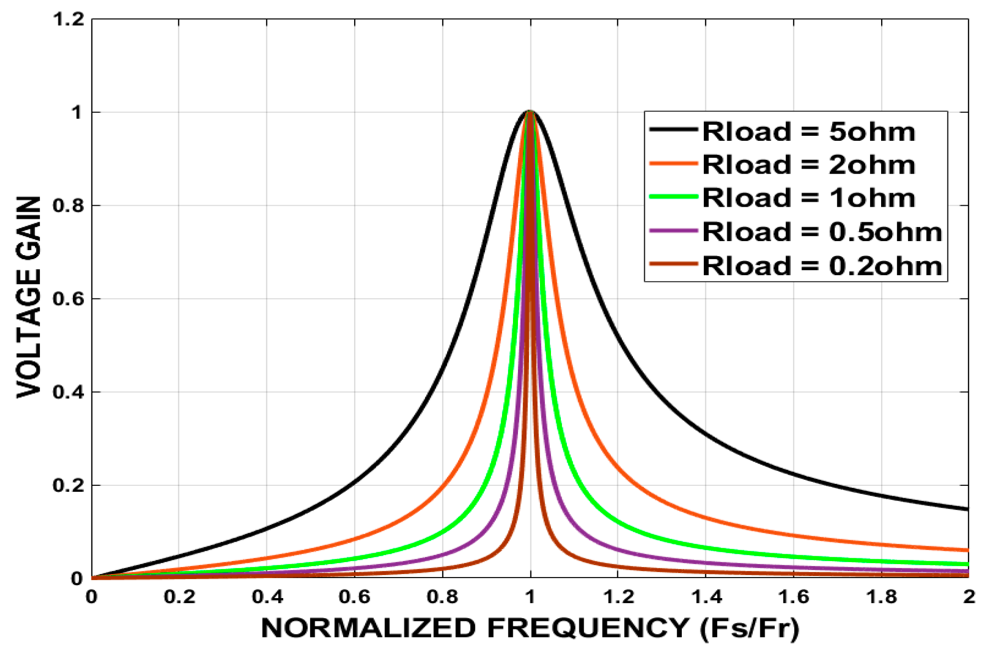
2.2. CLLC Converter with a Three-Winding Transformer for Bidirectional Power Transfer and Adjustable Voltage Gain

In the proposed system, a bidirectional CLLC converter with a three winding transformer is chosen to make bidirectional energy transfer possible. An additional winding is required to increase the voltage gain to compensate for the voltage drop in the components, and the winding selection switches (STr1 and STr2) are used for the voltage step-up operation in the case of reverse power transfer.
Figure 3 shows the voltage gain of the bidirectional CLLC converter at different load conditions. As shown in Figure 3, the maximum voltage gain of the CLLC converter reaches unity at resonant frequency. By considering the voltage differences between the battery cells (typically less than 200 mV) and the voltage drops in the components, the turn ratio of the transformer should be higher than 1 to obtain a suitable balancing current. The third winding of the transformer is required for reverse power transfer and its turn ratio needs to be less than 1 to achieve a step-up voltage gain. The converter operates at constant resonant frequency to achieve both zero-voltage switching (ZVS) turn-on and zero-current switching (ZCS) turn-off for all the active switches, and the efficiency of the charge transfer can be improved.

2.3. Operation Principle

Figure 4 shows a flow chart of the proposed balancing algorithm. Firstly, all of the voltages of the battery cells are measured with a monitoring IC, and the target voltage for the balancing is calculated. Then, two target cells for balancing can be selected. If the cells with the maximum and minimum voltages are located in different legs, they will then be selected for the balancing operation. Otherwise, the maximum-voltage cell will be chosen as the cell for discharge and another cell with a lower voltage in the other leg will be selected as the target cell for a charge. After the cell selection process, the selection switches connect the cells to the CLLC converter so that it can transfer the energy from a high-voltage cell to a low-voltage cell until one of them reaches the average value of the whole battery string. This process continues until all of the cells are balanced.

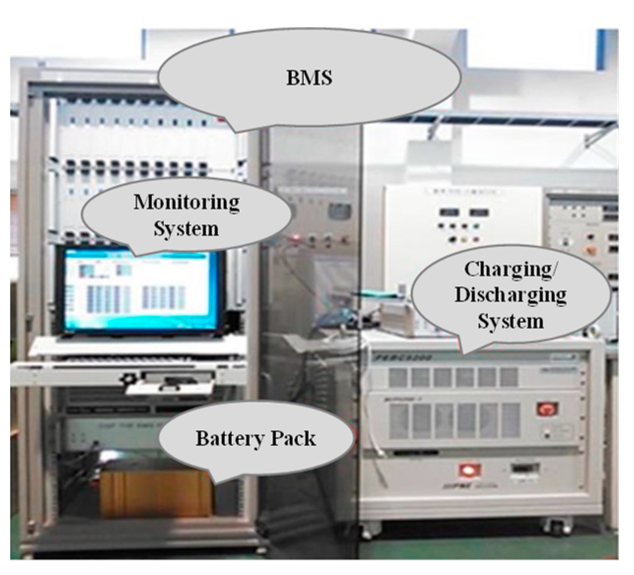
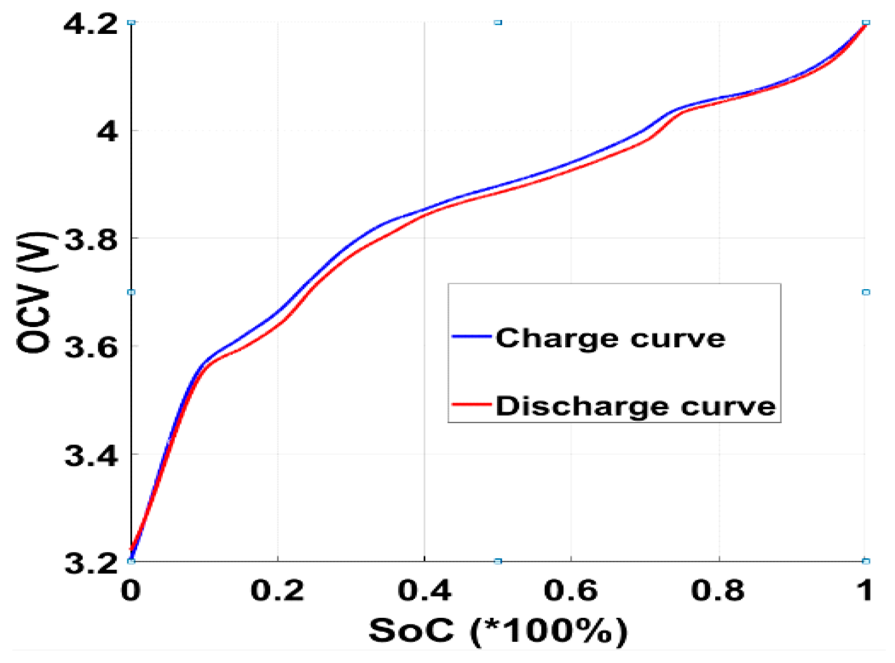
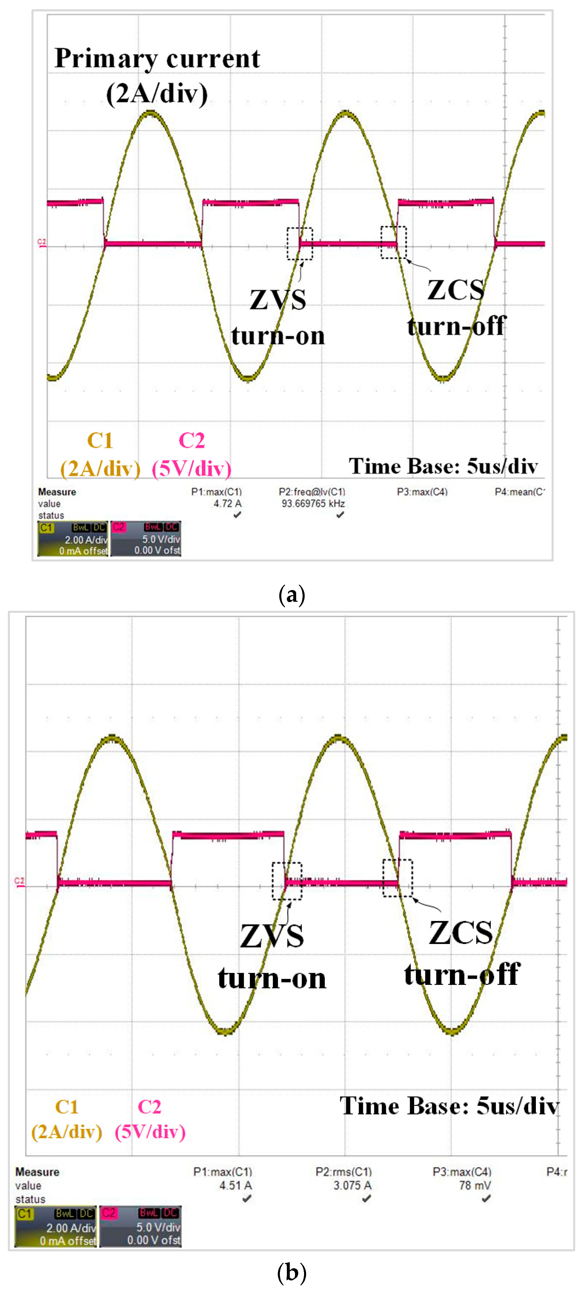
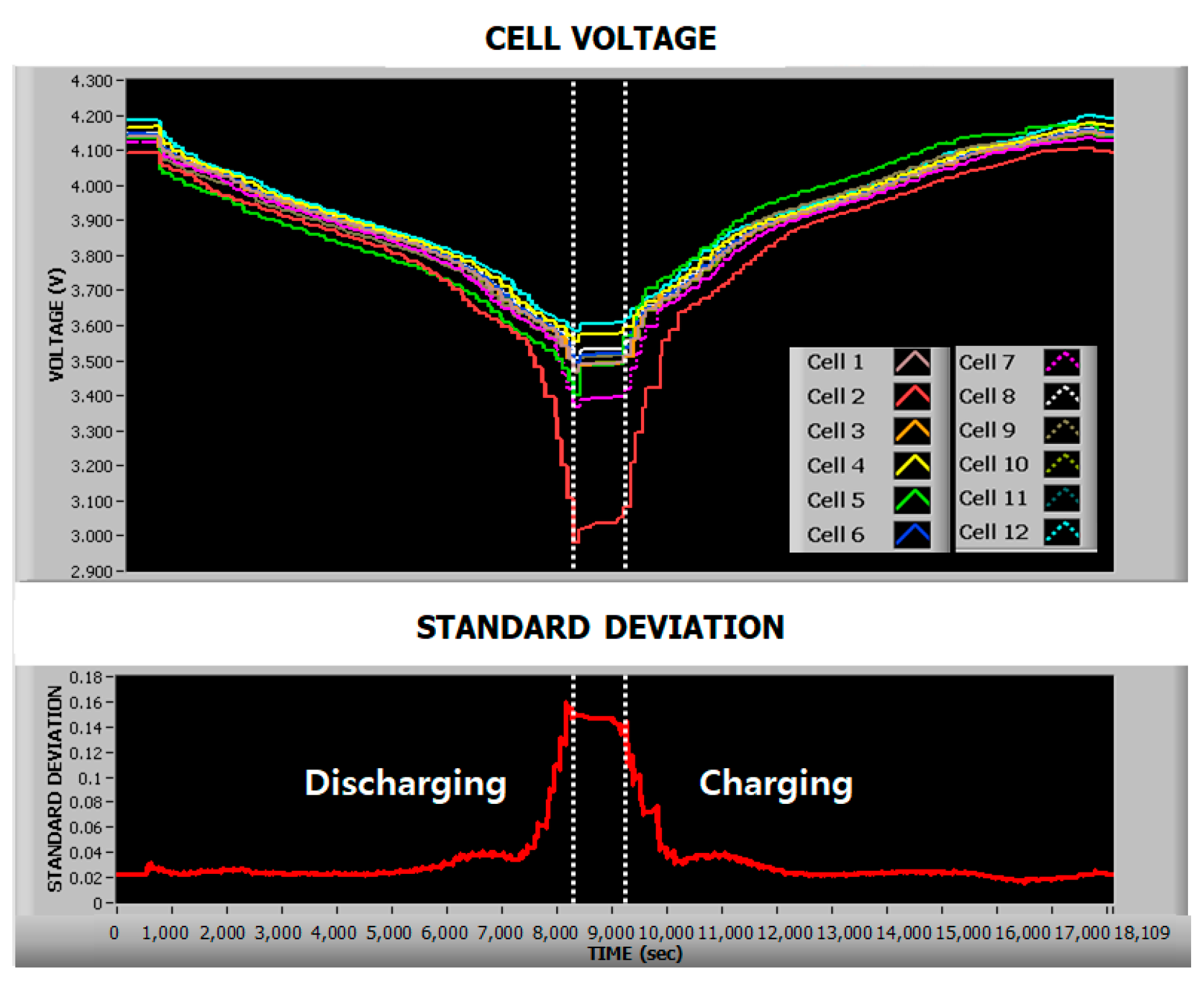
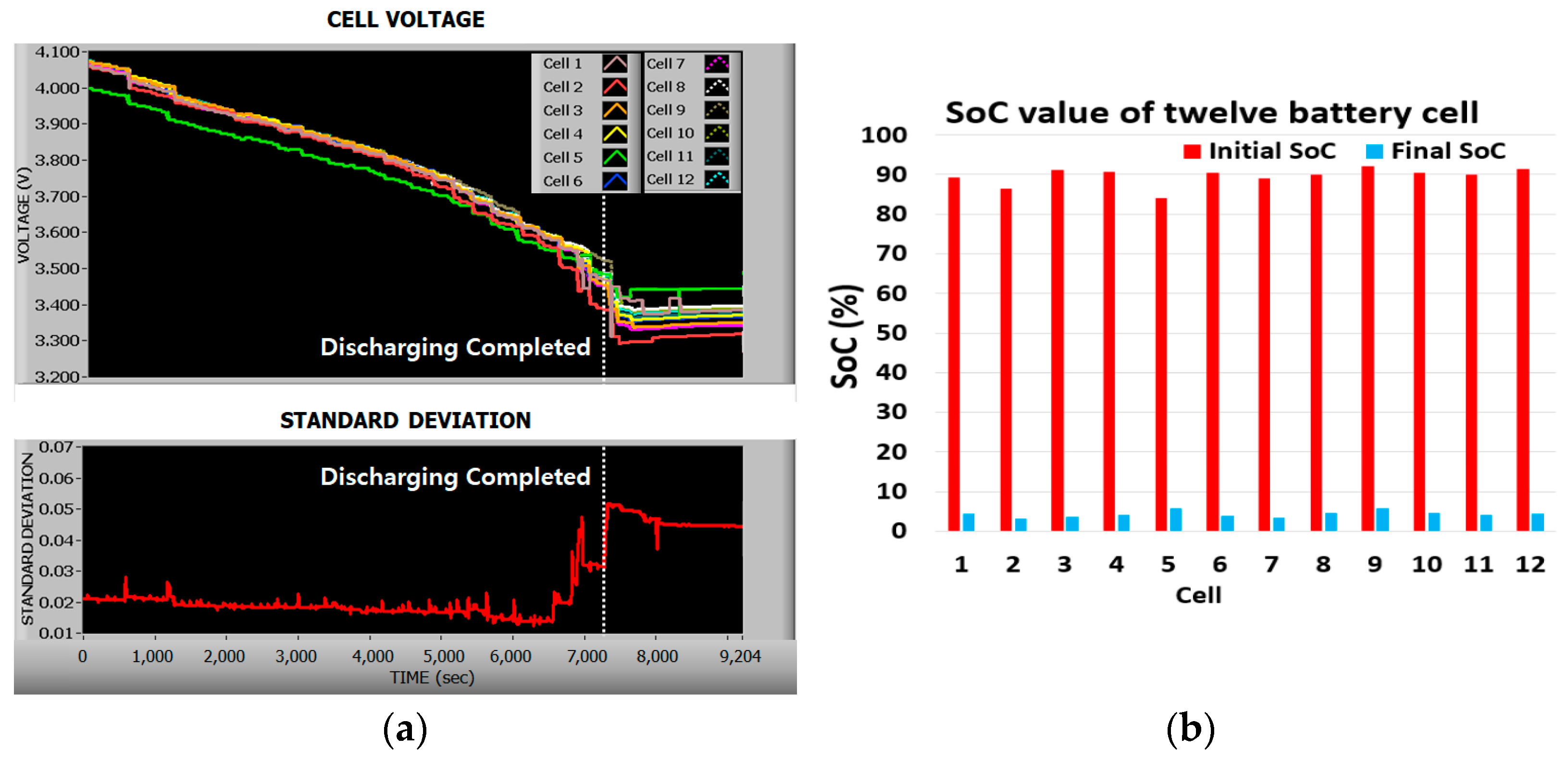
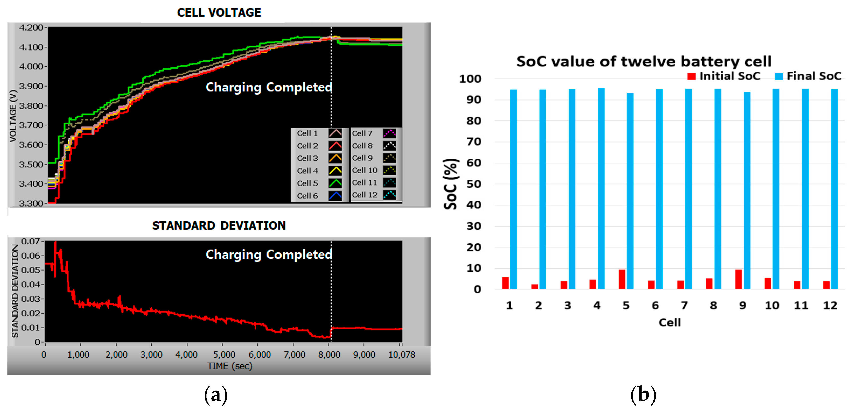
3. Experimental Results

To verify the operation of the proposed balancing circuit, a prototype of the balancing circuit is implemented for three EV battery modules from xEV (twelve lithium-ion batteries (74Ah), 4-series 2-parallel (4S2P) configuration), as shown in Figure 5. Figure 6 shows the SOC-OCV (open-circuit voltage) curve of the EV battery from xEV by using the Cubic Hermite method. Based on the SOC-OCV curve, the SOC value of each cell is calculated from the OCV value for further analysis in terms of balancing performance.
Figure 7 shows the voltage and current waveforms of the CLLC converter when the energy is transferred from the primary side to the secondary side and vice versa, as shown in Figure 7a and Figure 7b, respectively. As mentioned earlier, the MOSFET switch achieves both ZVS turn-on and ZCS turn-off. Figure 8 shows the efficiency curve of the CLLC converter with different battery cell voltages in both forward and backward power transfer. The maximum efficiency of the CLLC converter is 95.1% at a cell voltage of 4.2 V.
Figure 9 shows the results of the balancing operation during relaxation of the battery modules. The initial OCVs of twelve batteries are depicted in the second column of Table 1. As shown in Figure 9, cell 12 and cell 1 are chosen for the balancing operation. After 2000 s, cell 12 reaches the average voltage and the balancing between two cells is finished. Then, cell 4 and cell 1 can be selected as the highest and the lowest voltage cells. However, since these two cells are located in the same leg, cell 7 is selected instead of cell 1. The balancing between these two cells is completed at 3400 s. The balancing process continues until all of the cells become balanced with a maximum voltage difference of 7 mV. The final OCVs of twelve cells are presented in the third column of Table 1. The standard deviation of voltage cells after the balancing operation is reduced from 243 mV to 20 mV. The total SOC difference is reduced from 18.633% to 1.68%.
Figure 10 shows the voltage deviation among the cells when the balancing operation is not working. As shown in Figure 10, the standard deviation of the cell voltages grows from 0.02 V to 0.16 V at the end of discharge and reduces to 0.026 V at the end of a charge. At the end of discharge, the voltage at cell 2 quickly drops lower than 3 V, while the other cell voltages are higher than 3.4 V. It can be explained as cell 2 having a relatively lower initial SOC than that of others and hence reaching a lower SOC region than the others at the end of discharge, as shown in Figure 6. As can be found from Figure 6, the ΔOCV/ΔSOC is higher than that of other regions. Hence, the standard deviation of the cell voltages becomes larger at the end of a charge compared to the one at the beginning of a charge. Due to the difference in the initial SOCs of the cells and the nonlinearity of the SOC-OCV curve, the standard deviation of the cell voltages is changed nonlinearly. After a charge/discharge cycle, the standard deviation of the SOC increases from 2.45% to 3.64%.
Figure 11 and Figure 12 represent visual depictions regarding the effect of the balancing operation during discharge and a charge, respectively. Here, 20 A is applied to the battery during a charge and discharge. The cut-off pack voltage during discharge is 40.8 V (3.4 V × 12 cells).
The results of the balancing operation during discharge are shown in Figure 11a. Compared to the results during the discharge with no balancing operation in Figure 10, at the end of discharge, the cell voltages are converged to an average value of 3.4 V and their standard deviation is 0.05 V, much lower than 0.16 V compared to the case with no balancing operation. In the meantime, the standard deviation of the cell voltages at the end of a charge is larger than the initial value due to the higher slope in the SOC-OCV curve, as explained earlier. However, the maximum SOC difference between cells after a discharge is 2.61%, which is much lower than the 10.65% at the beginning. Figure 11b shows the initial and final SOCs of the cells. The standard deviation of the SOC is reduced from 2.26% to 0.77%, as summarized in Table 2.
Figure 12a shows the voltage deviation of the cells during a charge with the balancing operation. After the charge, the standard deviation of the cell voltages is reduced from 0.07 V to 0.004 V. The SOCs of cells before and after a charge are shown in Figure 12b. The standard deviation SOC is reduced from 2.2% to 0.63%, as summarized in Table 2.

4. Performance Analysis of the Proposed Method

4.1. Balancing Efficiency

Aside from analyzing the system’s energy transfer efficiency, assessments of the cell-balancing performance must weigh balancing proficiency as an additional vital metric. As discussed in [16], the balancing efficiency can be defined by the capacity loss and total capacity transferred during the balancing process, as shown in (1).
E B a l a n c i n g = Q t o t a l _ t r a n s f e r Q l o s s Q t o t a l _ t r a n s f e r
where EBalancing is the balancing efficiency, Qtotal_transfer is the total capacity transferred, and Qloss is the capacity loss during the balancing process.
Using (1), a balancing efficiency of up to 96.343% can be achieved for the proposed balancing topology during the relaxation time.

4.2. Comparison

In this section, a comparison between the proposed balancing topology and other DC2C topologies is shown in Table 3.
As can be seen from Table 3, the number of bidirectional switches and gate drivers of the proposed balancing topology is nearly a fourth compared to that of the topology in [25] and half in [23,24]. Moreover, the energy transfer efficiency and balancing efficiency are 89.4% and 96.34%, respectively, which proves the outstanding performance of the proposed method.

5. Conclusions

In this paper, a high-efficiency and low-cost active cell-to-cell balancing circuit for the reuse of EV batteries is proposed. The proposed circuit features a direct cell-to-cell balancing topology, consisting of a selection network and a three-port CLLC converter. In the proposed balancing topology, the number of bidirectional switches and gate drivers for the selection network is reduced by half compared to other DC2C topologies while maintaining a high-efficiency and high-speed balancing operation. The control of the CLLC converter is simple because it operates at a constant resonant frequency. Since the low-voltage-rating switches and the low-switching-frequency gate driver are used, both high efficiency and low cost can be achieved in the balancing circuit. Hence, the proposed balancing topology can be used for the reuse of EV batteries where the imbalance problem is more serious, and the cost is considered as one of the most important selection criteria.
In future work for our study, we aim to demonstrate the effectiveness of the proposed cell-to-cell balancing circuit in collaboration with a battery management system (BMS), particularly in the context of repurposing retired electric vehicle (EV) batteries for energy storage systems (ESSs). This investigation will clarify the circuit’s performance in optimizing the utilization of these batteries for a secondary application. Additionally, the proposed method will undergo an economic analysis to evaluate its cost-effectiveness in comparison to alternative methods. This aspect of the research will provide valuable insights into the feasibility and practicality of implementing the proposed approach on a broader scale, contributing to a comprehensive understanding of its potential in both technical and economic terms.

Author Contributions

Supervision, writing—review and editing, M.-C.D.; writing—original draft preparation, T.-T.L.; project administration, M.P. All authors have read and agreed to the published version of the manuscript.

Funding

This work was supported by the Korea Institute of Energy Technology Evaluation and Planning (KETEP) grant funded by the Korea government (MOTIE) (20225500000060, Operation System for AC/DC Hybrid Distribution Networks).

Data Availability Statement

The data presented in this study are available on request from the corresponding author.

Conflicts of Interest

The authors declare no conflict of interest.

References

  1. Sanguesa, J.A.; Torres-Sanz, V.; Garrido, P.; Martinez, F.J.; Marquez-Barja, J.M. A Review on Electric Vehicles: Technologies and Challenges. Smart Cities 2021, 4, 372–404. [Google Scholar] [CrossRef]
  2. Bharathidasan, M.; Indragandhi, V.; Suresh, V.; Jasiński, M.; Leonowicz, Z. A review on electric vehicle: Technologies, energy trading, and cyber security. Energy Rep. 2022, 8, 9662–9685. [Google Scholar] [CrossRef]
  3. O’Donovan, A. Electrified Transport Market Outlook 4Q 2023: Growth Ahead. Available online: https://about.bnef.com/blog/electrified-transport-market-outlook-4q-2023-growth-ahead/ (accessed on 30 January 2024).
  4. Xiao, J.; Jiang, C.; Wang, B. A Review on Dynamic Recycling of Electric Vehicle Battery: Disassembly and Echelon Utilization. Batteries 2023, 9, 57. [Google Scholar] [CrossRef]
  5. Haq, I.N.; Leksono, E.; Iqbal, M.; Sodami, F.N.; Kurniadi, D.; Yuliarto, B. Development of battery management system for cell monitoring and protection. In Proceedings of the IEEE 2014 International Conference on Electrical Engineering and Computer Science (ICEECS), Bali, Indonesia, 24–25 November 2014. [Google Scholar]
  6. Kelkar, A.; Dasari, Y.; Williamson, S.S. A Comprehensive Review of Power Electronics Enabled Active Battery Cell Balancing for Smart Energy Management. In Proceedings of the 2020 IEEE International Conference on Power Electronics, Smart Grid and Renewable Energy (PESGRE2020), Cochin, India, 2–4 January 2020. [Google Scholar]
  7. Naguib, M.; Kollmeyer, P.; Emadi, A. Lithium-Ion Battery Pack Robust State of Charge Estimation, Cell Inconsistency, and Balancing: Review March. IEEE Access 2021, 9, 50570–50582. [Google Scholar] [CrossRef]
  8. Hu, X.; Deng, X.; Wang, F.; Deng, Z.; Lin, X.; Teodorescu, R.; Pecht, M.G. A Review of Second-Life Lithium-Ion Batteries for Stationary Energy Storage Applications. Proc. IEEE 2022, 110, 735–753. [Google Scholar] [CrossRef]
  9. Kotak, Y.; Fernández, C.M.; Casals, L.C.; Kotak, B.S.; Koch, D.; Geisbauer, C.; Trilla, L.; Gómez-Núñez, A.; Schweiger, H.-G. End of Electric Vehicle Batteries: Reuse vs. Recycle. Energies 2021, 14, 2217. [Google Scholar] [CrossRef]
  10. Muhammad, M.; Ahmeid, M.; Attidekou, P.S.; Milojevic, Z.; Lambert, S.; Das, P. Assessment of spent EV batteries for second-life application. In Proceedings of the IEEE 4th International Future Energy Electronics Conference (IFEEC), Singapore, 24–28 November 2019. [Google Scholar]
  11. Matsuda, Y.; Tanaka, K. Reuse EV battery system for renewable energy introduction to island power grid. In Proceedings of the IEEE International Conference on Environment and Electrical Engineering and 2017 IEEE Industrial and Commercial Power Systems Europe (EEEIC/I&CPS Europe), Milan, Italy, 6–9 June 2017. [Google Scholar]
  12. Lei, B.; Shi, Y.; Zheng, Y.; He, Z.; Li, X.; Wu, Y. Economic and technical analysis of reusing second-life EV batteries in energy storage system. In Proceedings of the 18th International Conference on AC and DC Power Transmission (ACDC 2022), Online, 2–3 July 2022. [Google Scholar]
  13. Etxandi-Santolaya, M.; Casals, L.C.; Montes, T.; Corchero, C. Are electric vehicle batteries being underused? A review of current practices and sources of circularity. J. Environ. Manag. 2023, 338, 117814. [Google Scholar] [CrossRef] [PubMed]
  14. Al-Alawi, M.K.; Cugley, J.; Hassanin, H. Techno-economic feasibility of retired electric-vehicle batteries repurpose/reuse in second-life applications: A systematic review. Energy Clim. Chang. 2022, 3, 100086. [Google Scholar] [CrossRef]
  15. Aizpuru, I.; Iraola, U.; Canales, J.M.; Unamuno, E.; Gil, I. Battery pack tests to detect unbalancing effects in series connected Li-ion cells. In Proceedings of the IEEE 2013 International Conference on Clean Electrical Power (ICCEP), Alghero, Italy, 11–13 June 2013. [Google Scholar]
  16. Raeber, M.; Heinzelmann, A.; Abdeslam, D.O. Analysis of an Active Charge Balancing Method Based on a Single Nonisolated DC/DC Converter. IEEE Trans. Ind. Electron. 2021, 68, 2257–2265. [Google Scholar] [CrossRef]
  17. Gupta, P.P.; Kumar, N.; Nangia, U. Passive Cell Balancing and Battery Charge Controller with CCCV Topology. In Proceedings of the IEEE 2022 3rd International Conference for Emerging Technology (INCET), Belgaum, India, 27–29 May 2022. [Google Scholar]
  18. Faustino, B.; Lopes, N.V.; Costa, D.; Santos, H.; Vasco, J.; Capela, C.; Ferreira, C. Modular Lithium-Ion Cell Battery Management System with High Current Balancing. In Proceedings of the International Conference on Electrical, Computer, Communications and Mechatronics Engineering (ICECCME 2023), Online, 20–21 July 2023. [Google Scholar]
  19. Jeon, S.; Yun, J.-J.; Bae, S. Active cell balancing circuit for series-connected battery cells. In Proceedings of the IEEE 2015 9th International Conference on Power Electronics and ECCE Asia (ICPE-ECCE Asia), Seoul, Republic of Korea, 1–5 June 2015. [Google Scholar]
  20. Elvira, D.G.; Valderrama Blaví, H.; Bosque Moncusí, J.M.; Cid Pastor, À.; Garriga Castillo, J.A.; Martínez Salamero, L. Active Battery Balancing Via a Switched DC/DC Converter: Description and Performance Analysis. In Proceeding of the 16th Conference on Electrical Machines, Drives and Power Systems (ELMA), Varna, Bulgaria, 6–8 June 2019. [Google Scholar]
  21. Riczu, C.; Bauman, J. Implementation and System-Level Modeling of a Hardware Efficient Cell Balancing Cirucit for Electric Vehicle Range Extension. IEEE Trans. Ind. Appl. 2021, 57, 2883–2895. [Google Scholar] [CrossRef]
  22. Marcin, D.; Lacko, M.; Bodnár, D.; Pancurák, L.; Stach, L. Overview of Active Balancing Methods and Simulation of Capacitor Based Active Cell Balancing for Battery Pack in EV. In Proceedings of the 2023 International Conference on Electrical Drives and Power Electronics (EDPE), High Tatras, Slovakia, 25–27 September 2023. [Google Scholar]
  23. Pham, V.L.; Duong, V.T.; Choi, W. High-efficiency active cell-to-cell balancing circuit for Lithium-Ion battery modules using LLC resonant converter. J. Power Electron. 2020, 20, 1037–1046. [Google Scholar] [CrossRef]
  24. Shang, Y.; Zhang, C.; Cui, N.; Guerrero, J.M. A Cell-to-Cell Battery Equalizer with Zero-Current Switching and Zero-Voltage Gap Based on Quasi-Resonant LC Converter and Boost Converter. IEEE Trans. Power Electron. 2015, 30, 3731–3747. [Google Scholar] [CrossRef]
  25. Shang, Y.; Zhang, Q.; Cui, N.; Duan, B.; Zhou, Z.; Zhang, C. Multicell-to-Multicell Equalizers Based on Matrix and Half-Bridge LC Converters for Series-Connected Battery Strings. IEEE J. Emerg. Sel. Top. Power Electron. 2020, 8, 1755–1766. [Google Scholar] [CrossRef]
Figure 1. The proposed active direct cell-to-cell balancing circuit.
Batteries 10 00061 g001
Figure 2. A gate driver and its power supply for the selected network.
Batteries 10 00061 g002
Figure 3. The voltage gain of the bidirectional CLLC converter at different load conditions.
Batteries 10 00061 g003
Figure 4. Flow chart of the proposed balancing algorithms.
Batteries 10 00061 g004
Figure 5. Experimental setup for the proposed balancing method with EV battery modules from xEV.
Batteries 10 00061 g005
Figure 6. SOC-OCV curve of EV battery from xEV.
Batteries 10 00061 g006
Figure 7. Voltage and current waveforms at the switches Sa1 and Sb1: (a) MOSFET Sa1; (b) MOSFET Sb1.
Batteries 10 00061 g007
Figure 8. The efficiency of the CLLC converter at different battery cell voltages and currents.
Batteries 10 00061 g008
Figure 9. Cell voltages and their standard deviation with the balancing operation during relaxation.
Batteries 10 00061 g009
Figure 10. Voltage deviation during the charge/discharge with no balancing operation.
Batteries 10 00061 g010
Figure 11. Balancing operation during a discharge. (a) Cell voltages and their standard deviations. (b) SOC of cells.
Batteries 10 00061 g011
Figure 12. Balancing operation during a charge. (a) Cell voltages and their standard deviations. (b) SOC of cells.
Batteries 10 00061 g012
Table 1. OCV experimental results of twelve cells.
CellInitial OCV (V)Final OCV (V)
Cell 14.1494.143
Cell 24.14.138
Cell 34.1494.142
Cell 44.184.145
Cell 54.1534.143
Cell 64.154.145
Cell 74.1264.144
Cell 84.1414.142
Cell 94.1544.144
Cell 104.164.142
Cell 114.1374.145
Cell 124.24.145
Table 2. SOC standard deviation.
Operation ModeSOC Std. (Initial)SOC Std. (Final)
Discharging2.26%0.77%
Charging2.2%0.63%
Table 3. Comparison between the proposed topology and other DC2C topologies.
TopologyBidirectional
Switches
Gate DriveNo. of Fast Switches and Gate Drivers for Power Transfer Part
Pham, VL. et al. (Ref. [23])2N + 22N + 22 MOSFETs + 2 diodes + 1 gate driver for LLC resonant converter
Y. Shang et al. (Ref. [24])2N + 22N + 25 MOSFETs + 5 diodes + 3 gate drivers for LC and boost converter
Y. Shang et al. (Ref. [25])4N4N4 MOSFETs + 4 gate drivers for LC series resonant converter
Proposed methodN + 2N + 28 MOSFETs + 2 gate drivers for CLLC converter
Disclaimer/Publisher’s Note: The statements, opinions and data contained in all publications are solely those of the individual author(s) and contributor(s) and not of MDPI and/or the editor(s). MDPI and/or the editor(s) disclaim responsibility for any injury to people or property resulting from any ideas, methods, instructions or products referred to in the content.

