Abstract
Anode-free lithium batteries (AFLBs) present an opportunity to eliminate the need for conventional graphite electrodes or excess lithium–metal anodes, thus increasing the cell energy density and streamlining the manufacturing process. However, their attributed poor coulombic efficiency leads to rapid capacity decay, underscoring the importance of achieving stable plating and stripping of Li on the negative electrode for the success of this cell configuration. A promising approach is the utilization of lithiophilic coatings such as silver to mitigate the Li nucleation overpotential on the Cu current collector, thereby improving the process of Li plating/stripping. On the other hand, inkjet printing (IJP) emerges as a promising technique for electrode modification in the manufacturing process of lithium batteries, offering a fast and scalable technology capable of depositing both thin films and patterned structures. In this work, a Fujifilm Dimatix inkjet printer was used to deposit Ag sites on a Cu current collector, aiming to modulate the interfacial electrochemistry of the system. Samples were fabricated with varying areas of coverage and the electrochemical performance of the system was systematically evaluated from bare Cu (non-lithiophilic) to a designed pattern (partially lithiophilic) and the fully coated thin film case (lithiophilic). Increasing lithiophilicity resulted in lower charge transfer resistance, higher exchange current density and reduced Li nucleation overpotential (from 55.75 mV for bare Cu to 13.5 mV for the fully coated case). Enhanced half-cell cyclability and higher coulombic efficiency were also achieved (91.22% CE over 76 cycles for bare Cu, 97.01% CE over 250 cycles for the fully coated case), alongside more uniform lithium deposition and fewer macroscopic irregularities. Moreover, our observations demonstrated that surface patterning through inkjet printing could represent an innovative, easy and scalable strategy to provide preferential Li nucleation sites to guide the subsequent Li deposition.
1. Introduction
In response to the continuously growing demand for electronic devices and electric vehicles (EVs), the development of cost-effective rechargeable batteries with high energy and power density and prolonged cycle life is highly promoted. To date, lithium-ion batteries (LIBs) stand as one of the most extensively adopted energy storage technologies. Initially, the logic behind utilizing lithium (Li) metal as the anode was based on the fact that Li has the most negative standard electrochemical potential (−3.04 V vs. SHE) with an outstanding theoretical specific capacity (3862 mAh g−1) while being the lightest metal (0.534 g cm−3) [1,2,3]. Nevertheless, due to the inherent properties of Li metal, its utilization as an anode is associated with several challenges, including mossy or dendritic growth, formation of inactive lithium (“dead Li”), and volumetric expansion, which leads to the cracking of the solid electrolyte interphase (SEI) triggering continuous consumption of the electrolyte. Consequently, these issues result in low coulombic efficiency (CE) and rapid capacity decay during cycling [4,5,6,7].
Anode-free lithium batteries (AFLBs) without excess lithium have attracted much attention over the past decade. These batteries can achieve higher gravimetric and volumetric energy density by removing the anodic active material layer, which also simplifies the manufacturing process and reduces raw material and production costs [8,9]. However, AFLBs only have a limited lithium reservoir (N/P ratio = 1), thus any loss of lithium translates to a reduction in available capacity [10]. As the AFLB is being charged for the first time, lithium ions are extracted from the cathode and deposited onto the bare surface of the anode current collector, while during the discharge phase the plated lithium is stripped back to the cathode [9]. Conventional current collectors like copper have a high lithium nucleation overpotential, necessary to surpass the heterogeneous energy nucleation barrier due to the significant surface energy and crystal lattice mismatch between lithium and copper. This high nucleation overpotential promotes localized current density, leading to uneven nucleation and dendritic growth [11,12]. Therefore, achieving effective and stable cycling of lithium metal on the current collector (CC) substrate is crucial for the success of the AFLB’s cell concept [2,13].
Considerable efforts have been devoted to improving the cycling performance of Li on the Cu current collector through various strategies. Recent research has focused on the application of lithium-wetting (lithiophilic) metals or Li alloys in the form of thin film or nanoparticles on the surface of the current collector [14]. The working principle is based on the alloying reaction between the li ions and the lithiophilic metals (like Au, Ag, Zn, Mg) leading to the formation of the nuclei. The alloys formed on the surface then serve as preferential sites for the Li ions’ deposition, because of the high binding energy between the Li ions and the Li alloys. Moreover, these lithiophilic sites provide diffusion pathways for Li to move to the inner solid phase while also reducing the interfacial resistance [15,16,17,18]. Most Importantly, the Li nucleation overpotential is reduced as a result of this solid solution buffer layer which can guide the formation and growth of non-dendritic Li as shown by the work of Yan et al. [11].
Among the transition metals, in many experiments, Ag demonstrated superior electrochemical performance in anode-free configurations, whether used as an interlayer on the solid electrolyte surface or as a coating on the current collector [9,19,20,21]. This could be explained by the fact that both Li and Ag can dissolve in each other across the interface due to their close atomic radius and comparable crystalline structure [15,17]. Moreover, the stability of the substrate during cycles of alloying/dealloying is maintained by minor changes in the structure of the solid solution during phase transition. Simultaneously, traces of Ag in the newly formed Li maintain the lithiophilicity and continue to attract Li ions [14]. For instance, Cui et al. modified planar Cu collectors with Ag nanoparticles of about 50 nm via a substitution reaction [22], Xia et al. employed magnetron sputtering to deposit Ag nanoparticles of tens of nanometers densely distributed on Cu current collectors with a coating thickness of 400 nm [23] and Hou et al. coated commercial Cu foil with lithiophilic Ag nanoparticles using electroless plating uniformly covering the substrate with a granular structure [24]. These Ag modifications led to improved battery performance by lowering the nucleation overpotential, which in turn provided stable cycling performance, high coulombic efficiency, extended cycle stability and significantly enhanced capacity retention in full cells.
Patterned structured electrodes have shown significant potential in regulating Li cycling behavior and improving the overall performance of the battery, whether being applied for confining dendritic growth or to create preferential regions for Li plating stripping to happen. For example, Li et al. modified the surface of a Li electrode by a hexagonal pattern of micro-holes and revealed that not only is the Li species preferentially deposited into theses holes, but also that Li plating/stripping behavior was dependent on the geometry of these pores [25]. An alternative approach taken by Park et al. was to fabricate micro-patterned Li electrodes which resulted in lower Li nucleation overpotential as well as prolonged cycle life compared to the un-patterned electrode owing to better Li anchoring [26]. Another interesting idea presented by Zou et al. involved manipulating the electric field distribution by patterning the structure of the Cu current collector with a grid of micro-compartments. This modification successfully confined and redirected the Li dendrites laterally [27]. Lastly, the study of Yan et al. shed light on the preferential deposition of Li on the designed hollow gold-incorporated nano-capsules, and with this approach they mitigated dendrites while improving the stability of the electrode even in the corrosive carbonate electrolyte [11].
Many additive manufacturing (AM) methods have been studied for the fabrication or modification of battery elements [28,29,30]. In particular, Inkjet Printing (IJP) has emerged as a promising, cost-effective technique capable of fast and scalable deposition of both thin films and patterned structures of a wide variety of materials [31,32]. In this method, droplets of the desired ink are deposited on the substrate according to a user-defined design, enabling easy modification of the surface properties and minimizing material waste [28]. Although the formulation of inks is complex and printed structures are typically porous due to solvent evaporation, particularly with metal nanoparticles that require post-processing steps, inkjet printing (IJP) offers several key advantages over the previously mentioned techniques [22,23,24], including the following: (a) a wide range of commercially available inks exist, including those containing metal nanoparticles like silver; (b) IJP allows for the fabrication of patterned structures that can be easily modified by the operator, simply by adjusting the printing parameters and design. This flexibility is not achievable with the other techniques, which often require more complex procedures such as masking or lithography; (c) IJP provides good control over film thickness by adjusting the number of overprints. These advantages have enabled the successful use of inkjet printing in fabricating electrodes for lithium-ion batteries (LIBs) [33,34,35,36,37,38,39]. However, so far only poor attention has been paid to IJP as a powerful technique suitable for the interfacial modification of current collectors and surfaces, and its potential in AFLB applications is mostly unexplored.
In this work, a Fujifilm Dimatix inkjet printer was used to deposit Ag sites directly on the Cu thin foil collector, aiming to modulate the interfacial electrochemistry of the system. Samples were fabricated with varying areas of coverage, and the electrochemical performance of the system was systematically evaluated transitioning from bare Cu (non-lithiophilic) to a designed pattern (partially lithiophilic) and finally to the fully coated thin film case (lithiophilic). Potentiodynamic and galvanostatic electrochemical tests, supplemented by electrochemical impedance spectroscopy (EIS) and ex situ analysis via scanning electron microscopy (SEM) have been employed to characterize the silver printed structures. Our results clearly indicate that cyclability in the plating-stripping test and coulombic efficiency are related to the overall lithiophilicity of the substrate, with the best performance being offered by the fully coated sample (Ag10ds@Cu). Interestingly, ex situ SEM showed that the printed Ag dots effectively acted as preferential Li nucleation and growth sites. This study highlights the potential of IJP for guiding Li deposition to lithiophilic sites, underscoring its significance in advancing electrode engineering for battery applications involving lithium plating.
2. Materials and Methods
2.1. Sample Preparation and Ag Printing
Firstly, a piece of commercial Cu foil (15 µm thick) was cleaned by ultrasonic immersion in ethanol and acetone separately for 5 min each, rinsing with deionized water and drying with nitrogen gas.
The Cu foil was then moved to the flatbed of a Dimatix Materials Printer (DMP-2850, Fujifilm, Tokyo, Japan, piezoelectric Drop-on-Demand inkjet printer). Methalon JS-A211-S (Novacentrix, Austin, TX, USA) was used as the Ag ink, with 40 wt % silver nanoparticles (the z-average particle size = 30–50 nm) dispersed in an aqueous solution containing a fluoropolymer binder. Dimatix IJP was used to print patterns of dots with a diameter of roughly 28.89 ± 1.31 µm with different drop spacing (40 or 10 µm) in two layers of overprint, resulting in a coating thickness of 2.64 ± 0.05 µm. The obtained samples are denoted as AgXds@Cu, where “X” is the drop spacing. Samba cartridges were filled with 2.5 mL of the ink, which was jetted at 20 kHz jetting frequency through a single nozzle using a custom waveform and a nozzle voltage of 30 V. Printed samples were dried shortly on a heated plate at 60 °C in order to evaporate the solvent. Subsequently, sintering was conducted at 150 °C for 3 h (heating rate 10 °C min−1) in a tubular furnace, placing the samples inside a quartz vial under nitrogen gas flux of 10 L/h. The temperature setting was chosen based on the technical datasheet provided by the manufacturer.
2.2. Electrochemical Measurements
Electrodes (10 mm diameter) were obtained by punching the samples into round disks. Batteries were assembled in a half-cell configuration using CR-2025 coin cells in an argon-filled glove box (H2O < 0.5 ppm, O2 < 0.5 ppm) with one layer of Celgard 2500 separator and 20 µL of 1 M Lithium bis (trifluoromethanesulfonyl)imide (LiTFSI) in a solution of DOL:DME (1:1 volume ratio) with 3 wt % of LiNO3 as the electrolyte. Printed films were used as the working electrode and Li metal foil (12 mm diameter, 300 µm thick) as the counter/reference electrode. Cyclic voltammetry was operated by a multichannel Squidstat Prime potentiostat device (Admiral Instruments, Tempe, AZ, USA) at 0.5 mV s−1 scan rate in the range of 0.6 V to −0.2 V. Galvanostatic Charge/Discharge cycling of the batteries was performed using Neware battery testing system. The cells were cycled for a maximum of 250 cycles at 0.2 mAh cm−2 plating capacity and 0.2 mA cm−2 current density, preceded by 5 stabilization cycles at 0.05 mA cm−2. These values were specifically chosen to investigate the early stages of Li deposition. Electrochemical impedance spectroscopy (EIS) analysis was performed with a BioLogic electrochemical workstation (VSP) in the frequency range 7 MHz–100 mHz with a voltage pulse amplitude of 10 mV.
2.3. Structural and Morphological Characterization
Optical microscopy (Leica DM LM, Wetzlar, Germany) was used to capture images of the modified Cu foil after the sintering step. X-ray diffraction (XRD) measurements were conducted on Philips PW 1830 diffractometer (Philips, Amsterdam, The Netherlands) equipped with a vertical goniometer PW 1820. Scanning electron microscope (SEM) images were obtained with a ZEISS EVO 50 EP. In order to investigate Li deposition on the substrate, coin cells were disassembled inside an Argon filled glovebox and the electrodes were preliminary treated to remove the residual lithium salts/electrolyte solvent before performing SEM analysis. X-ray Fluorescence (XRF) analysis was performed using Fischerscope X-ray XAN by Fischer (Sindelfingen, Germany).
3. Results
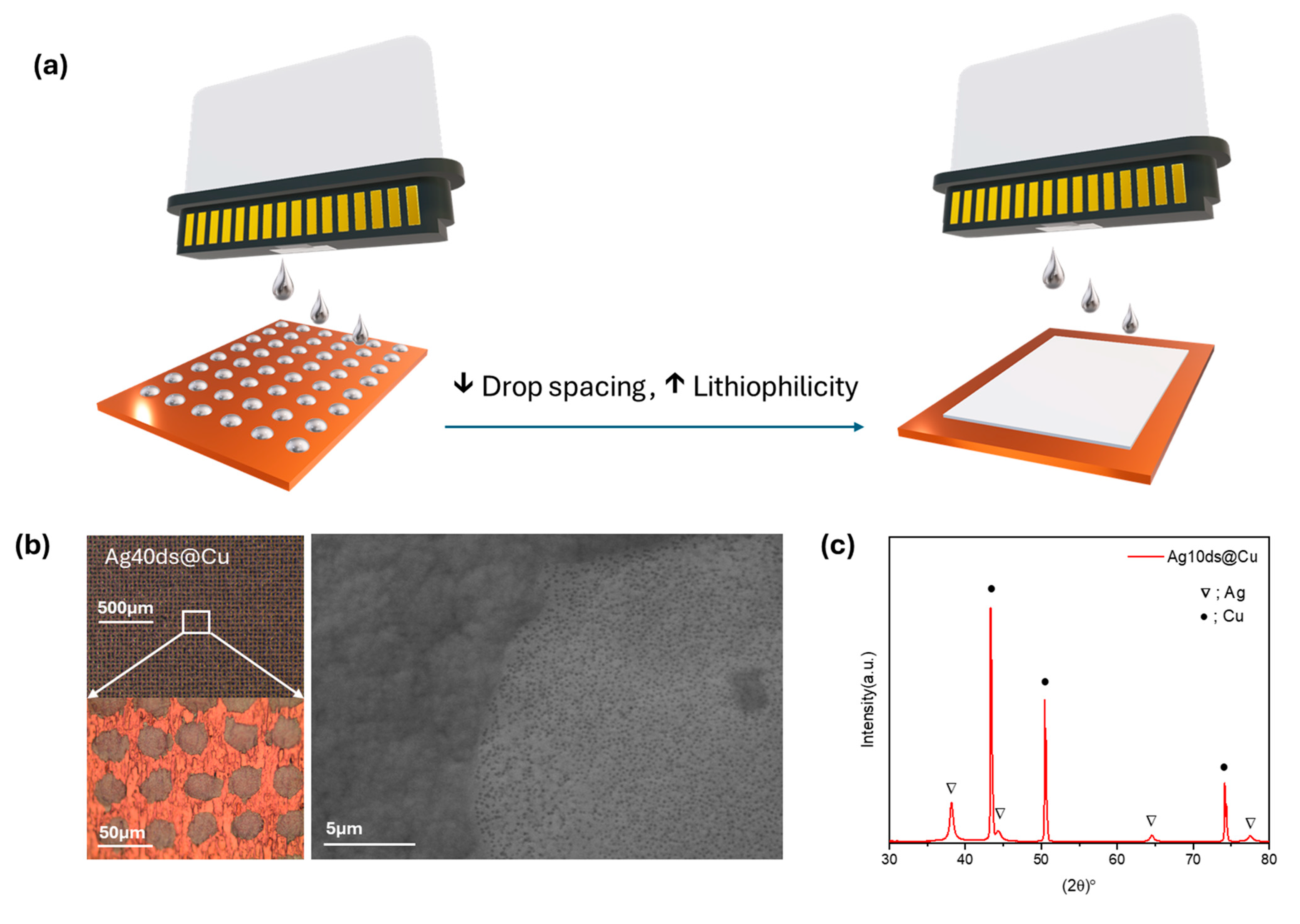
To demonstrate the viability of inkjet printing for tuning the interfacial electrochemistry of the current collectors in anode-free lithium batteries, silver nanoparticles were printed on the bare Cu foil as schematically shown in Figure 1a. In this work, Ag was chosen as the lithiophilic agent as a reference material both for Li interfacial regulation and inkjet printing application, since Ag nanoparticle inks are widely commercially available. The drop spacing, defined as the center-to-center distance of two consecutive printed dots, was changed as a parameter to obtain different surface coverages of Ag on the copper foil. Lithiophilic sites were printed at 40 µm and 10 µm drop spacing to achieve the partially coated (approximate areal coverage 45%) and fully coated samples. All samples were fabricated in two layers of overprint in order to ensure that the desired sites on the surface of the Cu foil are fully covered by Ag while minimizing coating thickness to theoretically achieve higher energy density. The average thickness of the silver coating was 2.64 ± 0.05 µm, measured by XRF.

Figure 1.
(a) Schematic representation of interfacial litiophilicity tuning by IJP of Ag nanoparticle ink. (b) Optical images of the Ag40ds@Cu sample after the thermal treatment and the SEM image of a single printed dot. (c) XRD of the Ag10ds@Cu after thermal treatment.
The optical images of the Ag40ds@Cu sample after heat treatment are shown in Figure 1b. The images confirmed a good matching of the actual printed pattern with the designed one, having an average dot size of 28.89 ± 1.31 µm spaced at 41.53 ± 0.77 µm. Nonetheless, the dot shape displayed some irregularities as it was affected by the Cu foil morphology and wettability, as well as the jetting process of the ink during printing and eventual satellite drop formation. According to the SEM analysis (Figure S1), the printed Ag coating exhibited a porous structure both before and after the curing process, with pores homogeneously distributed and measuring approximately tens of nanometers in diameter. After curing, the porosity slightly increased due to the complete evaporation of the solvent, though this did not significantly alter the overall microscopic structure. Figure 1c presents the XRD pattern of the printed sample Ag10ds@Cu after thermal treatment at 150 °C. It is observed that the diffraction peaks were strongly coinciding with the diffraction from crystalline Cu (JCPDS 98-005-3247) and Ag (JCPDS 01-087-0718), revealing the presence of well sintered silver nanoparticles providing a compact layer of on the Cu foil. EDS mapping of the pristine Ag10ds@Cu after heat treatment (Figure S2) presents the main ingredients of the fabricated electrode. The distribution of the fluoropolymer binder could be concluded to be homogeneous according to the elemental mapping of the fluorine on the substrate.
Cyclic voltammetries of half cells are presented in Figure 2a,b. Considering the first and fifth cycles of CVs, it is evident that by increasing the covered area with silver sites, the maximum current and overall charge achieved was increased both in plating and stripping steps. As the electrodes were polarized at low potential, Li ions reacted with the silver, forming a Ag-Li alloy (Equation (1)). Subsequently, at negative potentials, Li was plated on the Ag-Li alloy surface due to high bonding energy between the Li and Li-Ag alloy [16]. Silver can form infinite solid solutions with Li during lithiation/delithiation. Additionally, the diffusion of silver towards the deposited lithium maintains the lithiophilicity of the surface, unlike gold, which can only influence Li deposition in the initial stages of plating. In terms of phase transformations within the Ag/Li system, it is reported that, initially, a Ag-rich solid solution forms. As Li content increases with plating capacity, various alloys form sequentially through phase transitions, starting from LiAg and progressing to Li12.5Ag, eventually leading to a Li-rich solid solution with traces of diffused Ag [14,17]. In our case, despite the absence of clear cathodic and anodic fingerprint peaks related to the Ag lithiation and de-lithiation processes, the silver-coated electrodes turned dark after the first Li deposition (Figure S3), indicating the formation of the Ag-Li alloy [40].
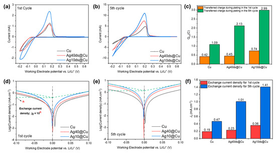
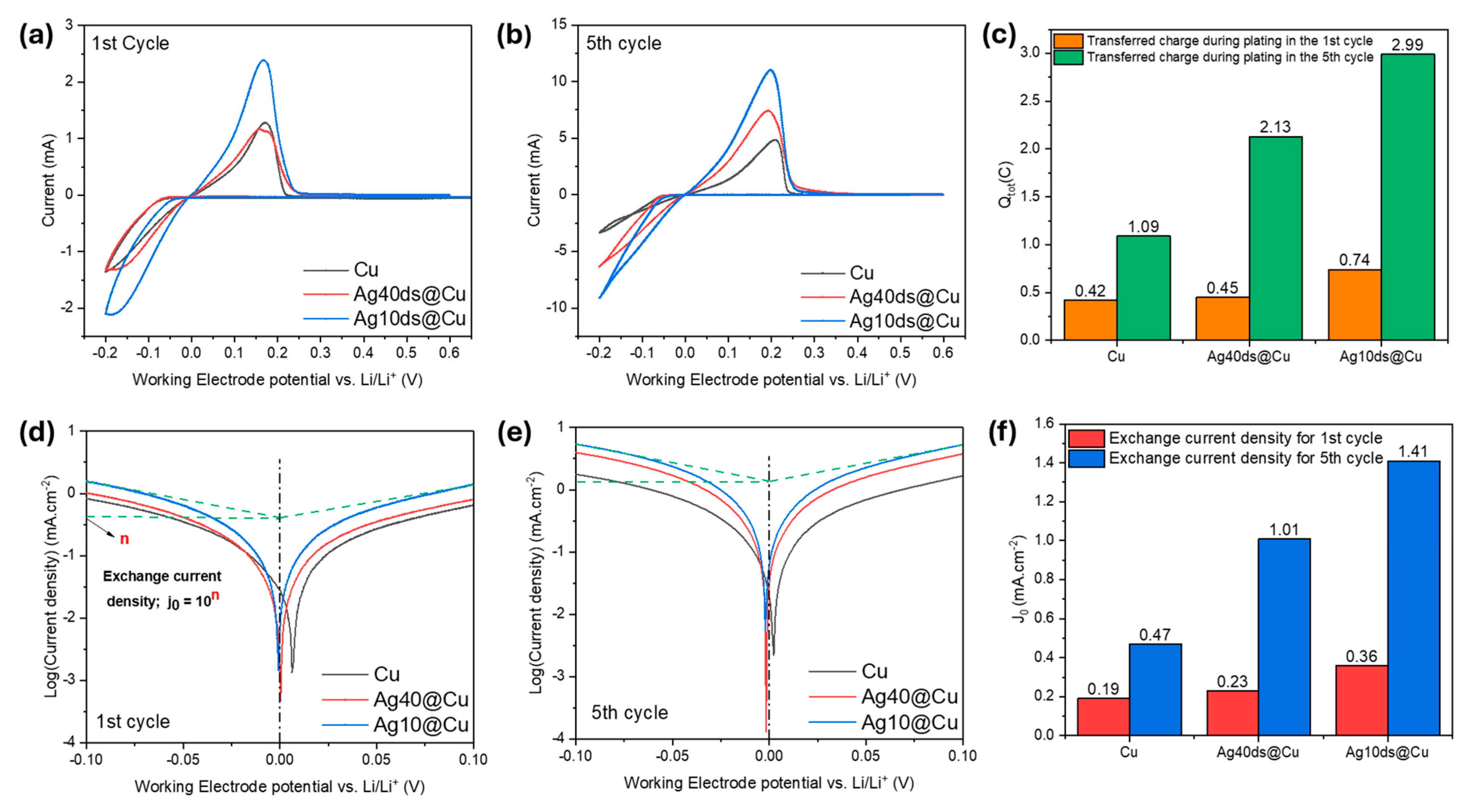
Figure 2.
Cyclic voltammetry plots of half cells batteries cycled between −0.2 and 0.6 V at 0.5 mV s−1 scan rate for the (a) 1st cycle and (b) 5th cycle. (c) Transferred charge values during the plating step in the first and fifth cycles. Tafel plots derived from CV; (d) 1st cycle, (e) 5th cycle. (f) Exchange current density values extrapolated from the Tafel plots.
Due to the above-mentioned reasons, the silver coatings exhibited catalytic functioning for the red-ox reaction, improving the kinetics of the electrochemical reaction.
Ag + xLi+ + xe− ← AgLix
Additionally, the amount of transferred charge during plating in the first and fifth cycles (Figure 2c) were also calculated. During the first cycle, the amount of transferred charge increased by about 74% from bare Cu (0.42 C) to Ag10ds@Cu (0.74 C). The higher transferred charge observed in Ag10ds@Cu compared to Ag40ds@Cu is attributed to the increased amount of lithiophilic material in the former. This provides a larger catalytic surface, which enhances the kinetics of Li deposition, resulting in a higher transferred charge during the initial Li plating process. After a few stabilization cycles (5th cycle), the same trend held as for bare Cu; the plating charge was 1.09 C, while for Ag10ds@Cu it was 2.99 C. Noteworthily, even though the partially lithiophilic coating of the Ag40ds@Cu electrode did not show a considerable improvement with respect to bare Cu for the first cycle (0.45 C), at the 5th cycle Ag40ds@Cu coherently showed a mixed behavior between bare Cu and a fully Ag-coated substrate. Its related charge was 2.13 C, demonstrating that even having just a partially lithiophilic coating could greatly improve the Li plating reaction kinetic.
In Figure 2d,e the Tafel plots, extracted from CVs in the potential window between −0.1 V and 0.1 V, are reported. From Tafel plots the exchange current density was extrapolated by fitting the linear part of the anodic and cathodic branches. Exchange current density (j0) is a meaningful parameter related to the red-ox reaction kinetic, and the higher it is, the higher is the reaction kinetic will be, owing to a lower charge-transfer resistance (Rct) according to Equation (2) [41,42]:
where T is the temperature, R is the gas constant (8.314 J mol−1 K−1), F is the Faraday constant (96,485 A s mol−1) and z is the electron moles. In summary, the j0 value is strictly correlated with the substrate affinity toward lithium plating (lithiophilicity) [43,44]. Comparing the j0 for the electrodes at the first and fifth cycle, it is clear that it increased across all samples after few stabilization cycles, because of SEI formation, microstructural (e.g., Li alloying for Ag-coated electrodes) and morphological modifications or residual plated lithium with respect the pristine surface. Considering the fifth cycle, the j0 values clearly reflected a coherent trend in terms of lithiophilicity trend with respect to the Ag surface coverage, moving from the bare Cu (0.47 mA cm−2), and the ~45 % in Ag40ds@Cu (1.01 mA cm−2), to 100% in Ag10ds@Cu (1.41 mA cm−2). These results demonstrated that current collector lithiophilicity can be easily tuned by adjusting the surface coverage with materials with a high Li affinity such as Ag.
Rct = RT/zFj0
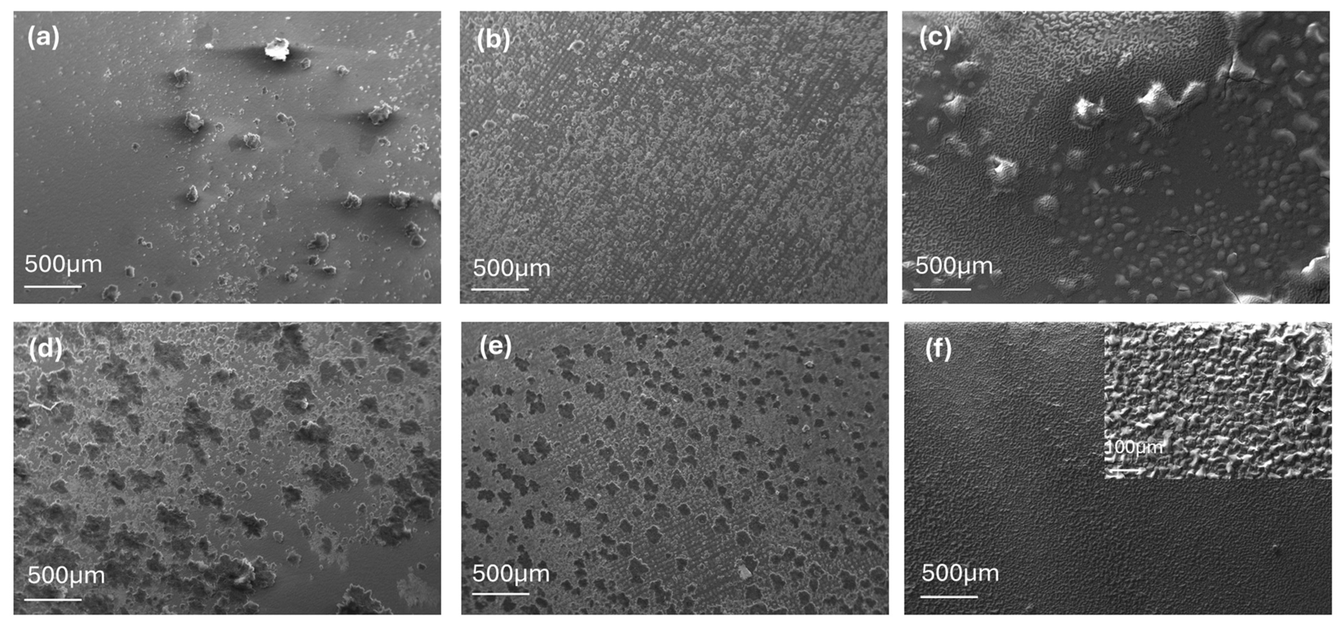
The SEM images of bare Cu, Ag40ds@Cu, and Ag10ds@Cu are reported both for a limited Li plating capacity of 0.006 mAh cm−2 (Figure 3a–c) and higher plating capacity of 0.2 mAh cm−2 (Figure 3d–f), representative of the Li incipient and full growth regime, respectively. The bare Cu exhibited highly irregular distribution of Li deposition due to its non-lithiophilic nature. Both small and big deposits were clearly visible on the Cu surface after nucleation (Figure 3a), and they irregularly coalesced during the full growth stage (Figure 3d). In the initial stages of Li plating, the Ag dots of Ag40ds@Cu (Figure 3b) clearly managed to achieve a more homogeneous distribution of small Li plated sites, mostly coincident with the underlying Ag dots that acted as preferential nucleation sites guiding a much more homogenous Li plating with respect to bare Cu, as similarly reported by Fan et al. [45]. In the full growth regime (Figure 3e), agglomeration into macroscopic aggregates occurred, but more regularly in shape and spatial distribution compared to bare Cu. In contrast, the surface morphology was very smooth for the incipient Li growth for the fully Ag-coated Ag10ds@Cu sample (Figure 3c). In particular, a smooth but wavy surface was evident at the full plated stage, with no evident Li macroscopic deposits being randomly distributed, as result of a 2D-like growth of Li as typical for Ag-modified electrodes [40,45,46,47,48].

Figure 3.
SEM images of electrode surfaces at limited Li-plated capacity (0.05 mA cm−2, 0.006 mAh cm−2); (a) bare Cu, (b) Ag40ds@Cu and (c) Ag10ds@Cu. SEM images of electrode surfaces for higher Li-plated capacity (0.05 mA cm−2, 0.2 mAh cm−2); (d) bare Cu, (e) Ag40ds@Cu, (f) Ag10ds@Cu.
Following five stabilization cycles, half cells were cycled for a maximum of 250 cycles. Coulombic efficiency (CE) serves as a quantitative metric in metal batteries to address the reversibility of the metal plating reaction as well as side reactions [49,50]. The voltage profiles of the samples with the corresponding CE plots are presented in Figure 4a,b. The bare Cu electrode showed stable cycling only up to 178 h with an average CE of 91.22 % over 76 cycles, after which the irregular cycling was evident from the associated voltage profile. The Ag10ds@Cu performed best in terms of cycling stability, smoothly achieving the 250-cycle limit with an average CE of 97.01 % over 250 cycles. Noteworthily, the partially Ag-coated Ag40ds@Cu electrode could keep up with the fully coated Ag electrode up to 138 cycles with an average CE of 96.28 %, after which CE dropped and irregular cycling occurred. Considering the CE across the initial 50 cycles, significant disparities in plating-stripping reversibility are revealed, related to the lithiophilicity of the electrodes. The CE observed in the bare copper was noticeably inferior when compared to the corresponding values for the Ag40ds@Cu and Ag10ds@Cu samples during the same cycle interval. This trend matched well with the ex situ SEM analyses previously reported, showing a great difference in the Li plating homogeneity according to the different Ag coverage of the copper surface.
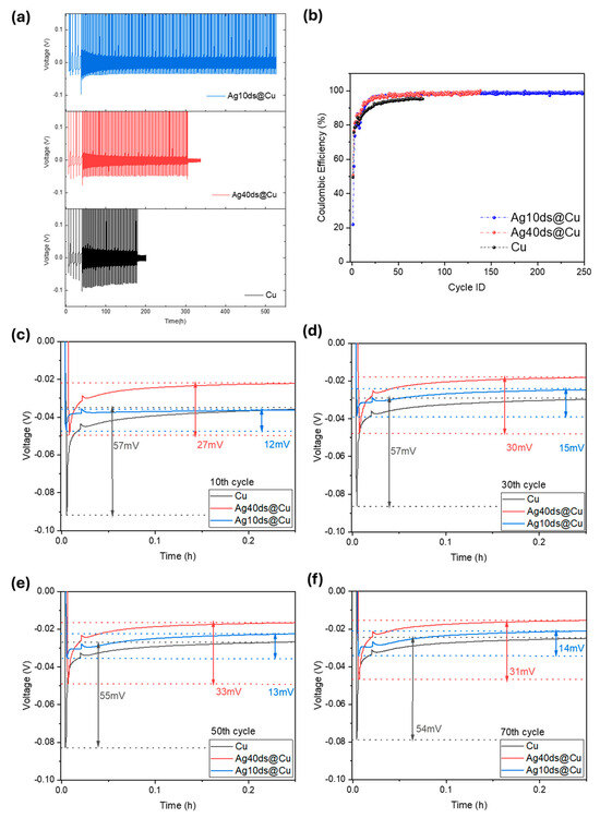
Figure 4.
(a) Voltage profiles of plating-stripping over a maximum of 250 cycles at 0.2 mA cm−2 and 0.2 mAh cm−2. The onset of irregular cycling, corresponding to a sudden drop of CE, was considered as a threshold for test stop. (b) Coulombic efficiency (CE %) with cycling. Voltage profiles and Li nucleation overpotentials observed from each electrode during cycling; (c) 10th cycle. (d) 30th cycle. (e) 50th cycle. (f) 70th cycle.
Figure 4c–f presents the voltage profiles of Li deposition and the nucleation overpotential from the 10th, 30th, 50th, and 70th cycles derived from the galvanostatic cycling test. The nucleation overpotential was determined by the voltage difference between the lowest point of the voltage dip and the stable region of the voltage plateau [11]. The average nucleation overpotential, calculated over the 10th, 30th, 50th, and 70th cycles, for the patterned sample Ag40ds@Cu is 30.25 mV, was significantly lower than the 55.75 mV observed for bare copper. The nucleation overpotential was obviously decreased when moving to the fully coated Ag40ds@Cu with only 13.5 mV, because of the buffer sites made of Li-Ag alloy formed at positive potentials, which would guide and regulate the formation and growth of Li metal [51,52]. Analyzing the trend across all samples clearly shows that increasing the density of printed lithiophilic sites consistently leads to a decrease in nucleation overpotential that is usually associated, as in our work, with prolonged cycling and higher CE. In general, these results highlight the effectiveness of inkjet printing in controllably adjusting the lithium affinity of the substrate. Based on the exchange current density values, we anticipated that samples with higher areal coverage would exhibit lower nucleation overpotential. Additionally, this decrease in nucleation overpotential was expected to enhance the plating/stripping behavior, leading to improved coulombic efficiency. These improvements were indeed observed in our data.
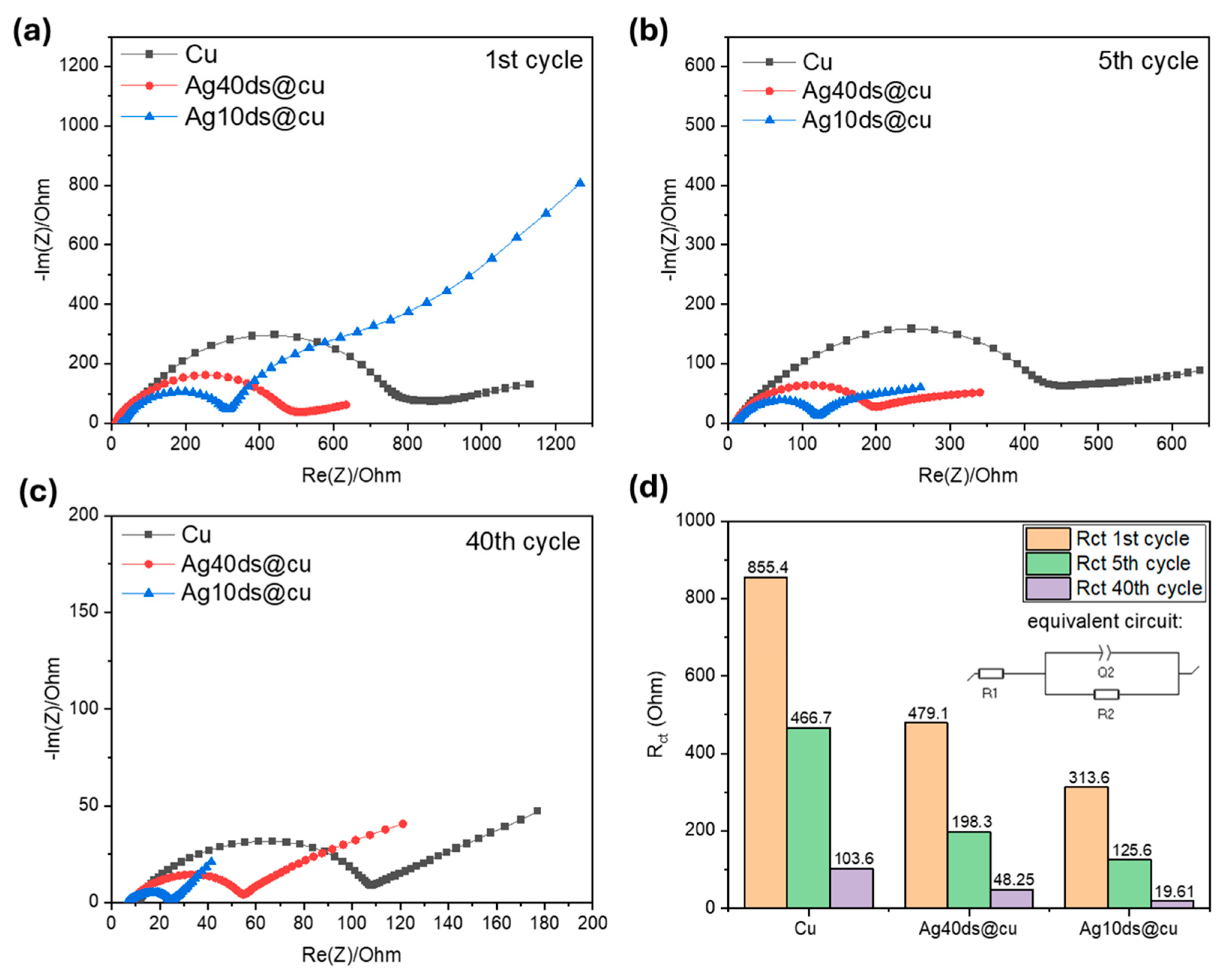
Figure 5 illustrates the electrochemical impedance spectroscopy (EIS) analysis of batteries in a half-cell configuration in a Li-plated condition. The Randles equivalent circuit was used to fit the data only on the first semi-circle of the Nyquist plot to evaluate the charge transfer resistance of the batteries [53]. The Nyquist plot for the first cycle reveals distinct semicircles for Cu, Ag40ds@Cu, and Ag10ds@Cu. The bare Cu sample exhibits the largest semicircle, indicating the highest Rct of 855.4 Ω. The Ag40ds@Cu and Ag10ds@Cu electrodes coherently demonstrated lower Rct, reflecting the higher Li reduction kinetic on the Ag-Li alloys, counting to 479.1 Ω and 313.6 Ω, respectively. The appearance of two semi-circles in Ag10ds@Cu after the first cycle can be attributed to the formation of the SEI layer and significant structural changes during the initial Li plating. Since the second semicircle disappeared in subsequent cycles, we concluded that this is likely due to the incomplete stabilization of the electrode during the first cycle. By the fifth cycle, after electrode stabilization, the semicircles were all reduced in size, as a result of structural modification, surface roughening and residual Li deposits. At the 40th cycle, the bare Cu sample still held the highest Rct at 103.6 Ω, with a notable difference between Ag40ds@Cu and Ag10ds@Cu, counting to 48.25 Ω and 19.61 Ω respectively, reflecting the nucleation overpotential trend previously described.

Figure 5.
Nyquist plots of the samples in Li-plated state (0.2 mAh cm−2, 0.1 mA cm−2); (a) 1st cycle, (b) 5th cycle and (c) 40th cycle; (d) charge transfer resistance values extracted by the fitting the plots with the equivalent circuit (inset image).
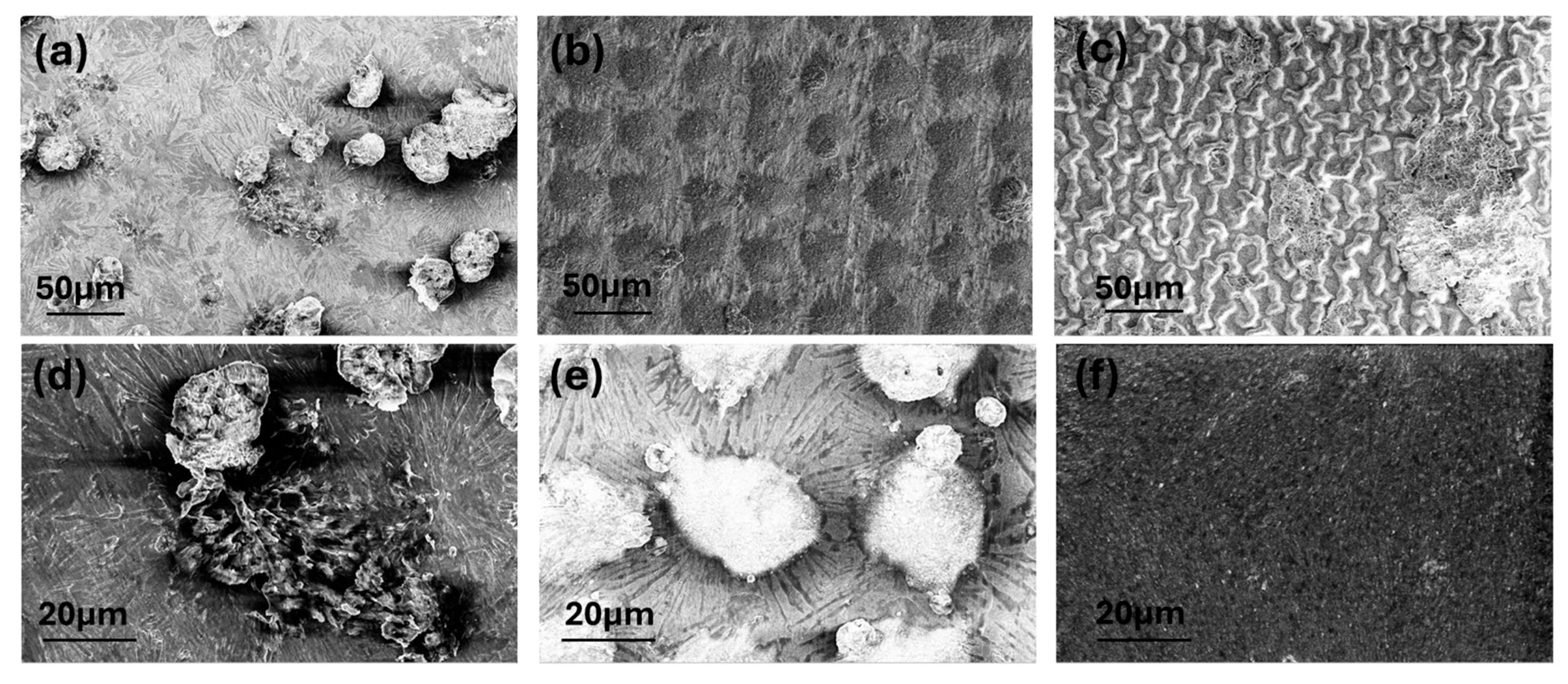
Half-cell batteries were then disassembled to examine the surface morphology of the deposited lithium on each sample and the structure of the coating after 40 cycles (Figure 6). On the bare Cu electrode (Figure 6a), irregular and mossy lithium growth as well as macro-scale deposits are evident, consistent with observations of Figure 3. However, at higher magnitude (Figure 6d), needle-like structures, associated with the on-growing Li crystals, cover the Cu surface with random orientations and they surround the macro-aggregates that obviously act as preferential nucleation sites. The Ag40ds@Cu sample (Figure 6b,e) displayed a much more regulated lithium plating. The morphology of the lithiated silver dots differed significantly from the uncoated areas. Interestingly, the needle-like shaped deposits are observed homogenously spreading out radially from the silver-coated regions, confined mainly to the copper parts, demonstrating that the Ag dots of the pattern aid in controlling lithium growth by offering preferential nucleation sites. In contrast, the Ag10ds@Cu sample (Figure 6c) maintained a smooth and shiny morphology, with a few thin Li aggregates emerging from the wavy surface and a porous but homogeneous surface being visible (Figure 6c), offering a higher surface area available even with respect to the Ag40ds@Cu, resulting in a uniform distribution of Li+ flux at the surface and reflecting the improved cyclability of the fully Ag-coated electrode.

Figure 6.
SEM images at different magnitudes of electrodes in a lithiated state (0.2 mAh cm−2) after 40 cycles cycled at 0.1 mA cm−2; (a,d) bare Cu, (b,e) Ag40ds@Cu and (c,f) Ag10ds@Cu.
4. Conclusions
In this work, we showed that the surface lithiophilicity of the copper current collector could be easily tuned through inkjet printing by adjusting the surface coverage of a high-lithium-affinity material. In particular, we produced both fully coated and partially coated (dot-patterned) electrodes by first printing and then sintering Ag nanoparticles. Due to the high affinity between Li and the Ag-Li alloy, the silver coatings exhibited catalytic function for the Li ion reduction. In general, the results of this work demonstrated that increasing the lithiophilicity through more extensive Ag coating significantly improved the interface electrochemistry, as reflected by lower charge transfer resistance and higher exchange current density, moving from bare Cu to Ag40ds@Cu and Ag10ds@Cu. For instance, the nucleation overpotential was decreased from 55.75 mV to 30.25 and 13.5 mV for bare Cu, Ag40ds@Cu and Ag10ds@Cu electrodes, respectively. Similarly, the overall half-cell cyclability was improved because of the higher CE of the inkjet-printed modified electrode with respect to bare Cu. Morphological ex situ analyses demonstrated that increasing the substrate lithiophilicity reduced the formation of macroscopic irregular Li deposits that, accumulating during cycling, are responsible for the onset of unstable battery cycling. In particular, Li crystals were shown to radially grow from the dots of the patterned Ag40ds@Cu sample. These observations demonstrated that surface patterning through inkjet printing could represent an innovative, easy and scalable strategy to guide lithium plating processes, promoting dendrite-free growth. Even though in our study the fully coated electrode outperformed the patterned one in half-cell cyclability, patterned coatings could be conveniently employed by proper design optimization through modeling and simulations.
Supplementary Materials
The following supporting information can be downloaded at: https://www.mdpi.com/article/10.3390/batteries10100369/s1, Figure S1: SEM images of the Ag10ds@Cu (a) after initial drying process at 60 °C, (b) after heat treatment at 150 °C for 3 h; Figure S2: Elemental mapping of the pristine Ag10ds@Cu after heat treatment at 150 °C; Figure S3: Optical Images of the Ag10ds@Cu: (a) pristine, (b) lithiated up to 0.2 mah·cm−2.
Author Contributions
Conceptualization, E.G.; methodology, E.G. and S.M.; software, E.G. and S.M.; validation, E.G. and S.M.; formal analysis, E.G. and S.M.; investigation, S.M.; resources, E.G., S.M. and L.M.; data curation, E.G. and S.M.; writing—original draft preparation, E.G. and S.M.; writing—review and editing, E.G., S.M. and L.M.; visualization, E.G. and S.M.; supervision, E.G. and L.M. All authors have read and agreed to the published version of the manuscript.
Funding
This research received no external funding.
Data Availability Statement
Data are contained within the article.
Conflicts of Interest
The authors declare no conflicts of interest.
References
- Tarascon, J.-M.; Armand, M. Issues and challenges facing rechargeable lithium batteries. Nature 2001, 414, 359–367. [Google Scholar] [CrossRef]
- Xie, Z.; Wu, Z.; An, X.; Yue, X.; Wang, J.; Abudula, A.; Guan, G. Anode-free rechargeable lithium metal batteries: Progress and prospects. Energy Storage Mater. 2020, 32, 386–401. [Google Scholar] [CrossRef]
- Qian, J.; Adams, B.D.; Zheng, J.; Xu, W.; Henderson, W.A.; Wang, J.; Wang, J.; Bowden, M.E.; Xu, S.; Hu, J.; et al. Anode-Free Rechargeable Lithium Metal Batteries. Adv. Funct. Mater. 2016, 26, 7094–7102. [Google Scholar] [CrossRef]
- Wang, Q.; Liu, B.; Shen, Y.; Wu, J.; Zhao, Z.; Zhong, C.; Hu, W. Confronting the Challenges in Lithium Anodes for Lithium Metal Batteries. Adv. Sci. 2021, 8, 2101111. [Google Scholar] [CrossRef]
- Fang, C.; Wang, X.; Meng, Y.S. Key Issues Hindering a Practical Lithium-Metal Anode. Trends Chem. 2019, 1, 152–158. [Google Scholar] [CrossRef]
- Whittingham, M.S. Lithium Batteries and Cathode Materials. Chem. Rev. 2004, 104, 4271–4302. [Google Scholar] [CrossRef]
- Lin, D.; Liu, Y.; Cui, Y. Reviving the lithium metal anode for high-energy batteries. Nat. Nanotechnol. 2017, 12, 194–206. [Google Scholar] [CrossRef]
- Heubner, C.; Maletti, S.; Auer, H.; Hüttl, J.; Voigt, K.; Lohrberg, O.; Nikolowski, K.; Partsch, M.; Michaelis, A. From Lithium-Metal toward Anode-Free Solid-State Batteries: Current Developments, Issues, and Challenges. Adv. Funct. Mater. 2021, 31, 2106608. [Google Scholar] [CrossRef]
- Tian, Y.; An, Y.; Wei, C.; Jiang, H.; Xiong, S.; Feng, J.; Qian, Y. Recently advances and perspectives of anode-free rechargeable batteries. Nano Energy 2020, 78, 105344. [Google Scholar] [CrossRef]
- Nanda, S.; Gupta, A.; Manthiram, A. Anode-Free Full Cells: A Pathway to High-Energy Density Lithium-Metal Batteries. Adv. Energy Mater. 2021, 11, 2000804. [Google Scholar] [CrossRef]
- Yan, K.; Lu, Z.; Lee, H.-W.; Xiong, F.; Hsu, P.-C.; Li, Y.; Zhao, J.; Chu, S.; Cui, Y. Selective deposition and stable encapsulation of lithium through heterogeneous seeded growth. Nat. Energy 2016, 1, 16010. [Google Scholar] [CrossRef]
- Zhang, R.; Chen, X.-R.; Chen, X.; Cheng, X.-B.; Zhang, X.-Q.; Yan, C.; Zhang, Q. Lithiophilic Sites in Doped Graphene Guide Uniform Lithium Nucleation for Dendrite-Free Lithium Metal Anodes. Angew. Chem. Int. Ed. 2017, 56, 7764–7768. [Google Scholar] [CrossRef]
- Zhang, S.S.; Fan, X.; Wang, C. A tin-plated copper substrate for efficient cycling of lithium metal in an anode-free rechargeable lithium battery. Electrochim. Acta 2017, 258, 1201–1207. [Google Scholar] [CrossRef]
- Zhang, S.; Yang, G.; Liu, Z.; Weng, S.; Li, X.; Wang, X.; Gao, Y.; Wang, Z.; Chen, L. Phase Diagram Determined Lithium Plating/Stripping Behaviors on Lithiophilic Substrates. ACS Energy Lett. 2021, 6, 4118–4126. [Google Scholar] [CrossRef]
- Li, J.; Su, H.; Liu, Y.; Zhong, Y.; Wang, X.; Tu, J. Li Alloys in All Solid-State Lithium Batteries: A Review of Fundamentals and Applications. Electrochem. Energy Rev. 2024, 7, 18. [Google Scholar] [CrossRef]
- Chen, X.-R.; Chen, X.; Yan, C.; Zhang, X.-Q.; Zhang, Q.; Huang, J.-Q. Role of Lithiophilic Metal Sites in Lithium Metal Anodes. Energy Fuels 2021, 35, 12746–12752. [Google Scholar] [CrossRef]
- Jin, S.; Ye, Y.; Niu, Y.; Xu, Y.; Jin, H.; Wang, J.; Sun, Z.; Cao, A.; Wu, X.; Luo, Y.; et al. Solid–Solution-Based Metal Alloy Phase for Highly Reversible Lithium Metal Anode. J. Am. Chem. Soc. 2020, 142, 8818–8826. [Google Scholar] [CrossRef]
- Gu, X.; Dong, J.; Lai, C. Li-containing alloys beneficial for stabilizing lithium anode: A review. Eng. Rep. 2021, 3, e12339. [Google Scholar] [CrossRef]
- Wondimkun, Z.T.; Tegegne, W.A.; Shi-Kai, J.; Huang, C.-J.; Sahalie, N.A.; Weret, M.A.; Hsu, J.-Y.; Hsieh, P.-L.; Huang, Y.-S.; Wu, S.-H.; et al. Highly-lithiophilic Ag@PDA-GO film to Suppress Dendrite Formation on Cu Substrate in Anode-free Lithium Metal Batteries. Energy Storage Mater. 2021, 35, 334–344. [Google Scholar] [CrossRef]
- Liu, Y.; Huang, S.; Wang, B.; Yang, Y.; Cao, G.; Xiong, Y.; Zhang, H. Interface structure regulation of a Ag lithiophilic layer towards uniform lithium nucleation/growth. Sustain. Energy Fuels 2019, 3, 2995–2999. [Google Scholar] [CrossRef]
- Chen, W.; Li, S.; Wang, C.; Dou, H.; Zhang, X. Targeted Deposition in a Lithiophilic Silver-Modified 3D Cu Host for Lithium-Metal Anodes. Energy Environ. Mater. 2023, 6, e12412. [Google Scholar] [CrossRef]
- Cui, S.; Zhai, P.; Yang, W.; Wei, Y.; Xiao, J.; Deng, L.; Gong, Y. Large-Scale Modification of Commercial Copper Foil with Lithiophilic Metal Layer for Li Metal Battery. Small 2020, 16, 1905620. [Google Scholar] [CrossRef]
- Xia, H.; Wang, D.; Wang, Y.; Fu, Z. Study on Stable Lithiophilic Ag Modification Layer on Copper Current Collector for High Coulombic-Efficiency Lithium Metal Anode. J. Electrochem. Soc. 2023, 170, 060546. [Google Scholar] [CrossRef]
- Hou, Z.; Yu, Y.; Wang, W.; Zhao, X.; Di, Q.; Chen, Q.; Chen, W.; Liu, Y.; Quan, Z. Lithiophilic Ag Nanoparticle Layer on Cu Current Collector toward Stable Li Metal Anode. ACS Appl. Mater. Interfaces 2019, 11, 8148–8154. [Google Scholar] [CrossRef]
- Li, Q.; Quan, B.; Li, W.; Lu, J.; Zheng, J.; Yu, X.; Li, J.; Li, H. Electro-plating and stripping behavior on lithium metal electrode with ordered three-dimensional structure. Nano Energy 2018, 45, 463–470. [Google Scholar] [CrossRef]
- Park, J.; Kim, D.; Jin, D.; Phatak, C.; Cho, K.Y.; Lee, Y.-G.; Hong, S.; Ryou, M.-H.; Lee, Y.M. Size effects of micro-pattern on lithium metal surface on the electrochemical performance of lithium metal secondary batteries. J. Power Sources 2018, 408, 136–142. [Google Scholar] [CrossRef]
- Zou, P.; Wang, Y.; Chiang, S.-W.; Wang, X.; Kang, F.; Yang, C. Directing lateral growth of lithium dendrites in micro-compartmented anode arrays for safe lithium metal batteries. Nat. Commun. 2018, 9, 464. [Google Scholar] [CrossRef]
- Sztymela, K.; Rossignol, F.; Bienia, M.; Zapp, N.; Nikolowski, K.; Cerbelaud, M. Fabrication of 3D silicon anode by inkjet printing: Opportunities and challenges. J. Energy Storage 2024, 75, 109567. [Google Scholar] [CrossRef]
- Rodriguez, R.; Deiner, L.J.; Tsao, B.H.; Fellner, J.P. Aerosol Jet-Printed LFP Cathodes with Bimodal Pore Distribution Improve the Rate Capability of LIB Cells. ACS Appl. Energy Mater. 2021, 4, 9507–9512. [Google Scholar] [CrossRef]
- Deiner, L.J.; Jenkins, T.; Powell, A.; Howell, T.; Rottmayer, M. High Capacity Rate Capable Aerosol Jet Printed Li-Ion Battery Cathode. Adv. Eng. Mater. 2019, 21, 1801281. [Google Scholar] [CrossRef]
- Zhou, S.; Usman, I.; Wang, Y.; Pan, A. 3D printing for rechargeable lithium metal batteries. Energy Storage Mater. 2021, 38, 141–156. [Google Scholar] [CrossRef]
- Clement, B.; Lyu, M.; Sandeep Kulkarni, E.; Lin, T.; Hu, Y.; Lockett, V.; Greig, C.; Wang, L. Recent Advances in Printed Thin-Film Batteries. Engineering 2022, 13, 238–261. [Google Scholar] [CrossRef]
- Park, M.-S.; Hyun, S.-H.; Nam, S.-C. Mechanical and electrical properties of a LiCoO2 cathode prepared by screen-printing for a lithium-ion micro-battery. Electrochim. Acta 2007, 52, 7895–7902. [Google Scholar] [CrossRef]
- Huang, J.; Yang, J.; Li, W.; Cai, W.; Jiang, Z. Electrochemical properties of LiCoO2 thin film electrode prepared by ink-jet printing technique. Thin Solid Films 2008, 516, 3314–3319. [Google Scholar] [CrossRef]
- Milroy, C.A.; Jang, S.; Fujimori, T.; Dodabalapur, A.; Manthiram, A. Inkjet-Printed Lithium–Sulfur Microcathodes for All-Printed, Integrated Nanomanufacturing. Small 2017, 13, 1603786. [Google Scholar] [CrossRef]
- Lawes, S.; Sun, Q.; Lushington, A.; Xiao, B.; Liu, Y.; Sun, X. Inkjet-printed silicon as high performance anodes for Li-ion batteries. Nano Energy 2017, 36, 313–321. [Google Scholar] [CrossRef]
- Sztymela, K.; Bienia, M.; Rossignol, F.; Mailley, S.; Ziesche, S.; Varghese, J.; Cerbelaud, M. Fabrication of modern lithium ion batteries by 3D inkjet printing: Opportunities and challenges. Heliyon 2022, 8, e12623. [Google Scholar] [CrossRef]
- Zhao, Y.; Zhou, Q.; Liu, L.; Xu, J.; Yan, M.; Jiang, Z. A novel and facile route of ink-jet printing to thin film SnO2 anode for rechargeable lithium ion batteries. Electrochim. Acta 2006, 51, 2639–2645. [Google Scholar] [CrossRef]
- Zhao, Y.; Liu, G.; Liu, L.; Jiang, Z. High-performance thin-film Li4Ti5O12 electrodes fabricated by using ink-jet printing technique and their electrochemical properties. J. Solid State Electrochem. 2009, 13, 705–711. [Google Scholar] [CrossRef]
- Zuo, Z.; Zhuang, L.; Xu, J.; Shi, Y.; Su, C.; Lian, P.; Tian, B. Lithiophilic Silver Coating on Lithium Metal Surface for Inhibiting Lithium Dendrites. Front. Chem. 2020, 8, 109. [Google Scholar] [CrossRef]
- Kim, M.; Lee, J.; Kim, Y.; Park, Y.; Kim, H.; Choi, J.W. Surface Overpotential as a Key Metric for the Discharge–Charge Reversibility of Aqueous Zinc-Ion Batteries. J. Am. Chem. Soc. 2023, 145, 15776–15787. [Google Scholar] [CrossRef]
- Xie, X.; Liang, S.; Gao, J.; Guo, S.; Guo, J.; Wang, C.; Xu, G.; Wu, X.; Chen, G.; Zhou, J. Manipulating the ion-transfer kinetics and interface stability for high-performance zinc metal anodes. Energy Environ. Sci. 2020, 13, 503–510. [Google Scholar] [CrossRef]
- Liu, Y.; Xu, X.; Sadd, M.; Kapitanova, O.O.; Krivchenko, V.A.; Ban, J.; Wang, J.; Jiao, X.; Song, Z.; Song, J.; et al. Insight into the Critical Role of Exchange Current Density on Electrodeposition Behavior of Lithium Metal. Adv. Sci. 2021, 8, 2003301. [Google Scholar] [CrossRef]
- Zhang, Z.; Zhou, X.; Liu, Z. Optimization of lithium nucleation by current density toward dendrite-free Li metal anode. J. Alloys Compd. 2022, 893, 162389. [Google Scholar] [CrossRef]
- Fan, H.; Gao, C.; Dong, Q.; Hong, B.; Fang, Z.; Hu, M.; Lai, Y. Silver sites guide spatially homogeneous plating of lithium metal in 3D host. J. Electroanal. Chem. 2018, 824, 175–180. [Google Scholar] [CrossRef]
- Niu, S.; Zhang, S.-W.; Li, D.; Wang, X.; Chen, X.; Shi, R.; Shen, N.; Jin, M.; Zhang, X.; Lian, Q.; et al. Sandwiched Li plating between Lithiophilic-Lithiophobic gradient Silver@Fullerene interphase layer for ultrastable lithium metal anodes. Chem. Eng. J. 2022, 429, 132156. [Google Scholar] [CrossRef]
- Han, K.H.; Seok, J.Y.; Kim, I.H.; Woo, K.; Kim, J.H.; Yang, G.G.; Choi, H.J.; Kwon, S.; Jung, E.I.; Kim, S.O. A 2D Ultrathin Nanopatterned Interlayer to Suppress Lithium Dendrite Growth in High-Energy Lithium-Metal Anodes. Adv. Mater. 2022, 34, 2203992. [Google Scholar] [CrossRef]
- Tian, R.; Chen, R.; Xu, Z.; Wan, S.; Guan, L.; Duan, H.; Li, H.; Zhu, H.; Sun, D.; Liu, H. Electrodeposition behavior of lithium metal on carbon substrates with surface silvering. Carbon 2019, 152, 503–510. [Google Scholar] [CrossRef]
- Xiao, J.; Li, Q.; Bi, Y.; Cai, M.; Dunn, B.; Glossmann, T.; Liu, J.; Osaka, T.; Sugiura, R.; Wu, B.; et al. Understanding and applying coulombic efficiency in lithium metal batteries. Nat. Energy 2020, 5, 561–568. [Google Scholar] [CrossRef]
- Yang, F.; Wang, D.; Zhao, Y.; Tsui, K.-L.; Bae, S.J. A study of the relationship between coulombic efficiency and capacity degradation of commercial lithium-ion batteries. Energy 2018, 145, 486–495. [Google Scholar] [CrossRef]
- Yang, C.; Yao, Y.; He, S.; Xie, H.; Hitz, E.; Hu, L. Ultrafine Silver Nanoparticles for Seeded Lithium Deposition toward Stable Lithium Metal Anode. Adv. Mater. 2017, 29, 1702714. [Google Scholar] [CrossRef]
- Liu, Z.; Ha, S.; Liu, Y.; Wang, F.; Tao, F.; Xu, B.; Yu, R.; Wang, G.; Ren, F.; Li, H. Application of Ag-based materials in high-performance lithium metal anode: A review. J. Mater. Sci. Technol. 2023, 133, 165–182. [Google Scholar] [CrossRef]
- Orazem, M.E.; Ulgut, B. On the Proper Use of a Warburg Impedance. J. Electrochem. Soc. 2024, 171, 040526. [Google Scholar] [CrossRef]

Disclaimer/Publisher’s Note: The statements, opinions and data contained in all publications are solely those of the individual author(s) and contributor(s) and not of MDPI and/or the editor(s). MDPI and/or the editor(s) disclaim responsibility for any injury to people or property resulting from any ideas, methods, instructions or products referred to in the content. |
© 2024 by the authors. Licensee MDPI, Basel, Switzerland. This article is an open access article distributed under the terms and conditions of the Creative Commons Attribution (CC BY) license (https://creativecommons.org/licenses/by/4.0/).