Article

Effects of Storage Voltage upon Sodium-Ion Batteries

by
Tengfei Song
1,*,
Brij Kishore
1,
Yazid Lakhdar
1,
Lin Chen
1,
Peter R. Slater
2 and
Emma Kendrick
1,*
1
School of Metallurgy and Materials, University of Birmingham, Edgbaston B15 2TT, UK
2
School of Chemistry, University of Birmingham, Edgbaston B15 2TT, UK
*
Authors to whom correspondence should be addressed.
Batteries 2024, 10(10), 361; https://doi.org/10.3390/batteries10100361
Submission received: 24 August 2024 / Revised: 27 September 2024 / Accepted: 8 October 2024 / Published: 11 October 2024

Abstract

:
Sodium-ion batteries (SIBs) are gaining attention as a safer, more cost-effective alternative to lithium-ion batteries (LIBs) due to their use of abundant and non-critical materials. A notable feature of SIBs is their ability to utilize aluminum current collectors, which are resistant to oxidation, allowing for safer storage at 0 V. However, the long-term impacts of such storage on their electrochemical performance remain poorly understood. This study systematically investigates how storage conditions at various states of charge (SOCs) affect open circuit voltage (OCV) decay, internal resistance, and post-storage cycling stability in two different Na-ion chemistries: Prussian white//hard carbon and layered oxide//hard carbon. Electrochemical Impedance Spectroscopy before and after storage shows a pronounced increase in internal resistance and a corresponding decline in cycling performance when SIBs are stored in a fully discharged state (0 V), particularly for layered oxide-based cells, illustrating the sensitivity of different SIB chemistries to storage conditions. Additionally, a novel reformation protocol is proposed that reactivates cell capacity by rebuilding the solid electrolyte interphase (SEI) layer, offering a recovery path after prolonged storage. These insights into the long-term storage effects on SIBs provide new guidelines for optimizing storage and transport conditions to minimize performance degradation, making them more viable for commercial applications.

1. Introduction

Lithium-ion batteries (LIBs) have become the most popular choice in the electrochemical energy storage market as they have a high energy density, long cycle life, mature supply chain, and declining costs. However, the safety of LIBs during storage and transportation remains a significant concern due to their susceptibility to thermal runaway and potential for fires or explosions [1,2,3]. This risk is particularly acute during air transportation, prompting strict regulations regarding transport conditions. To mitigate the risks associated with thermal runaway and to ensure safety, LIBs are required to be transported with a state of charge (SOC) limited to 30% or less [4,5,6], and extensive packing and isolation protocols should be followed to ensure complete safety considerations [6,7]. These precautions help to reduce the possibility of thermal runaway, especially in the event of physical damage or internal short circuits. However, such regulations increase the complexity and cost of LIB logistics.
Although it might seem intuitive that completely discharging a LIB to zero energy (the voltage to 0 V) for transportation is the safest measure, this practice can cause other issues due to the materials used in LIBs. LIBs with graphite as the negative electrode typically use copper foil as the current collector. When discharged to 0 V, the potential of the negative electrode can rise to about 3 V vs. Li/Li+, leading to the oxidation of Cu into Cu+ or Cu2+. This oxidation weakens adhesion between the graphite and copper foil, increasing the battery’s internal resistance. Moreover, the dissolved copper may deposit on the positive electrode during subsequent charging cycles, forming copper dendrites that could eventually lead to a short circuit [8,9].
Sodium-ion batteries (SIBs) have emerged in the energy storage sector over the last 10 years. Although they may not match LIBs in terms of energy density, SIBs have gained market attention for their low cost and sustainability characteristics due to the higher natural abundance of sodium and wide availability of non-critical transition metals that can be used in such cells [10,11,12,13]. SIBs’ safety characteristics are another significant advantage. Faradion Limited has systematically studied the safety properties of SIBs and found that their SIB, using sodium transition metal layered oxides and a hard carbon (HC) system, can be safely stored and shipped in a fully discharged state (zero volts) without the risk of adverse reactions. They also discovered that their SIB can be physically shorted for months without compromising subsequent cycling stability [4,14]. This capability stems from the use of aluminum as the negative electrode current collector in SIBs, which can eliminate the copper dissolution that occurs in LIBs when the cell is discharged to 0 V. This attribute offers great potential for simplifying the transportation process and enhancing safety by reducing the potential chemical activity within the battery [15]. However, it remains to be seen whether this ‘0 V stability’ can be extended to the other two sodium-ion battery chemistries, namely polyanionic compounds//hard carbon and Prussian analogues//hard carbon. Desai et al. conducted a comparative study on the post-electrochemical performance of Na3V2(PO4)2F3 (NVPF)//hard carbon (HC) and layered oxide (LO)//hard carbon (HC) systems by holding them at 0 V for between 24 and 72 h for every five cycles. They found that the SEI film will dissolve after storage at 0 V but regenerate during the subsequent charging process. This cycle of dissolution and regeneration leads to a loss of active sodium inventory and an increase in internal resistance, which in turn deteriorates cycling stability. The study also revealed that 0 V storage has a more significant impact on the cycling stability of the NVPF//HC system compared to the LO//HC system. This difference is attributed to the varying potentials of HC when the cell is discharged to 0 V: the potential of HC rises to 3.7 V vs. Na/Na+ with NVPF as the positive electrode, whereas it only reaches 2.7 V vs. Na/Na+ with LO as the positive electrode. A higher potential accelerates dissolution of the SEI film, further compromising cycle stability [16]. Some initial safety testing has been performed on LO systems, and instabilities in the SEI layer have been shown [17]. These findings indicate that sodium-ion batteries’ 0 V storage characteristics vary across electrochemical systems. The effects of storage conditions on Prussian white (PW), which is another promising cathode material for SIBs [18], have not been extensively studied or reported. Furthermore, after the battery is produced, it may be stored in a factory or transit (such as during sea transportation) for several months before reaching an end user. However, the impacts of long-term storage on post-electrochemical performance, such as irreversible capacity loss and cycling stability, are poorly understood.
This study focuses on understanding how different states of charge (SOCs) and storage conditions affect the performance of two Na-ion configurations: Prussian white//hard carbon and in-house layered oxide//hard carbon systems. Particular attention was given to storage at SOCs below 30%, based on practical considerations for transport safety. The innovations in this work lie in the comprehensive investigation of how long-term storage at different states of charge (SOCs) impacts the performance of sodium-ion batteries (SIBs). The study reveals that storing SIBs in a fully discharged state (0 V) leads to a significant increase in internal resistance and a decline in cycling stability, particularly for layered oxide-based cells. A key outcome is the development of a reformation protocol that can rebuild the solid electrolyte interphase (SEI) layer, allowing the recovery of lost capacity and improved cycling performance after storage. The work provides new guidelines for optimizing storage and transport conditions, advancing the viability of SIBs for commercial use.

2. Materials and Methods

2.1. Materials Preparation

2.1.1. Prussian White//Hard Carbon Chemistry (PW//HC)

Prussian white (PW) cathode material was supplied by Altris (Uppsala, Sweden). Electrode slurry was prepared by mixing 93% PW, 4% carbon black (C-NERGY C65, Willebroek, Belgium), 1% CMC (BVH8, Ashland, Schaffhausen, Switzerland), and 2% SBR (BM451B, Zeon, Tokyo, Japan). Hard carbon (HC) anode material was purchased from Kuraray (Type 1, Kuranode, Tokyo, Japan), and the electrode was prepared by mixing HC material, CMC, SBR, and conductive additive (C-NERGY C65, Willebroek, Belgium) in a mass ratio of 96:1:2:1.

2.1.2. Layered Oxide//Hard Carbon Chemistry (NMST//HC)

Layered oxide NaNi1/2Mn1/4Ti1/8Sn1/8 O2 (named NMST hereafter) was synthesized by a solid-state method in-house by mixing stoichiometric proportions of Na2CO3, Ni(NO3)2·6H2O, MnCO3, SnO2, and TiO2. The electrode was prepared by mixing 98% NMST powder, 6% carbon black (C-NERGY C65), and 6% PVDF (5130, Solvay). The anode material is the same as used in the PW//HC system.
All the obtained slurries were coated onto Al foil (16 um) and vacuum-dried at 120 °C for 24 h. The exception was the PW electrode, which was dried at 150 °C to remove crystal water that is difficult to eliminate at a lower temperature. These cells were assembled in a coin cell CR2032 format with PW or NMST as the positive electrode and HC as the negative electrode. The diameters for positive and negative electrodes were 14.8 mm and 15.0 mm, respectively. The electrodes were balanced such that the ratio of areal capacities of negative and positive electrodes was ~1.1. The cells were assembled in a glovebox with oxygen and a moisture concentration <0.1 ppm. A Dreamweaver nonwoven membrane was used as a separator and was soaked in 70 μL 1 M NaPF6 in EC: DEC (3:7 v/v%) electrolyte.

2.2. Electrochemical Performance

OCV and electrochemical performance were tested on a BCS (Bio-Logic, Seyssinet-Pariset, France) battery test system. Before storage, a formation step was performed for the cells in a voltage window of 1.3–3.8 V (for PW//HC) and 1.0–4.2 V (for NMST//HC) at 0.1 C for 2 cycles. The cells were subsequently charged to different states of charge (SOCs) at 0.1 C and stored at 25 °C for 2 months. The SOC was calculated based on their formation capacities. The OCV of each cell was monitored and recorded regularly during storage. After storage, these cells were cycled to assess the impact of storage conditions on electrochemical performance (capacity and cyclability). Electrochemical Impedance Spectroscopy (EIS) was tested before and after storage on a Biologic VMP3 battery testing system from 1 MHz to 1 mHz with an amplitude of 5 mA. Before conducting EIS, all the stored batteries were adjusted to 2.75 V at a current density of 10 mA g−1 for comparison. Three repeats of each condition were performed to ensure reproducibility.

3. Results

3.1. PW//HC Full Cell System

Initially, the evaluation of storage conditions on cell electrochemical performance was conducted based on the PW//HC full cell system. The basic electrochemical properties of the cathode and anode materials used are shown in Figure S1.
Figure 1a shows the voltage profile of PW//HC cells for two formation cycles in a voltage window of 1.3–3.8 V at 0.1 C (1 C = 140 mA g−1). After formation, the cells were either charged to various SOCs (0–100%) based on their formation capacity or fully discharged to 0 V as shown in Figure 1b. Once the current ceased, a voltage drop or rise (0% SOC and 0 V discharge) was observed as is expected from cathode and anode thermodynamics. Therefore, after being charged to specific SOCs, the cells were rested for 2 h to reach equilibrium, and the open circuit voltage (OCV) was then recorded and used as the starting point of the storage period. To examine the ‘0 V capability’, cells discharged to 0 V and then further short-circuited by copper wire wrapping were also tested.
Each cell’s open circuit voltage (OCV) was monitored for two months, and the changes in OCV are shown in Figure 1c, which represents the average of three cells. The OCV remained at 0 V for the shorted and stored cell. The decay rates in OCV during storage were calculated and shown in Figure 1d. The largest decay in OCV was observed for cells discharged to 0 V and 0% SOC and the cells that charged to 100% SOC, which means storage at either too high or too low SOCs is not preferable. A relatively stable OCV was obtained between 50% and 75% SOC for the stored cells. For the 0% SOC cell, the OCV decreased from 1.975 V to 1.620 V (Figure 1c), resulting in a total change of 17.95% (Figure 1d). In contrast, for the 0 V Dis cell, the OCV decreased from 1.966 V to 1.300 V (as shown in Figure 1c), yielding a total change of 33.84% (Figure 1d).
Cycling tests were then conducted to evaluate the effect of the state of charge during storage on the subsequent cycling stability. The charge/discharge was carried out at 0.2 C charge and 1 C discharge, with a slower 0.2 C charge/discharge cycle every 20 cycles to check the polarization as shown in Figure 2a. The reference cell represents a condition in which the cells were subjected to two cycles of formation and then cycling without storage. Cycle life data are observed to be best for the reference cell over 100 charge/discharge cycles. Cells stored at 75% SOC, 50% SOC, and 25% SOC exhibit comparable cycling performance to the reference cell. Interestingly, shorted cells performed better than expected, highlighting the potential for a PW//hard carbon system SIB to be transported under short conditions. By contrast, cells that experienced the largest changes in OCV during the storage period (0 V, 0% SOC, and 100% SOC) behaved with the poorest cycling stability when discharged at 1 C. However, their capacities all remained stable when discharged at 0.2 C every 20 cycles as illustrated in Figure 2b,c. For instance, after 100 cycles, the 0 V stored cells exhibited a capacity of only 60 mAh g−1 when discharged at 1 C. In contrast, the capacity jumped to 107 mAh g−1 when discharged at 0.2 C (Figure 2b), indicating significant polarization within those cells.
To understand the processes occurring in the cells during storage, EIS was performed before and after storage. Figure 3 shows the Nyquist plots and fitted parameters of cells before and after storage. All the cells experienced an increase in impedance after 2 months of storage, and the increase was related to the storage conditions. The lower the SOC, the greater the increase in internal resistance, and the shorted cells show the largest increase in impedance during storage. Thus, the cycling phenomena can be explained by the highly increased internal resistance after storage, which makes the cells not capable of being discharged repeatedly at a high C rate (1 C here).

3.2. NMST//HC Full Cell System

A storage and stability study was conducted on NMST//HC full cells to repeat the above results. The basic electrochemical properties of the NMST cathode material used are shown in Figure S2a,b. The voltage profile of a NMST//HC full cell for two formation cycles in a voltage window of 1.0–4.2 V at 0.1 C (1 C = 100 mA g−1), and the voltage profiles for charging or discharging the cells to various SOCs are shown in Figure S2c,d.
The changes in OCV during storage are illustrated in Figure 4a,b. As observed in PW//HC chemistry, cells that were either fully discharged (0% SOC and 0 V) or fully charged (100% SOC) exhibited larger declines in OCV than those that were partially charged. Cycling testing was then conducted at 1 C/1 C for charge/discharge, with a slower 0.2 C/0.2 C rate to assess the capacity every 25 cycles within the voltage window of 1.0–4.0 V. As depicted in Figure 4c, cells with large changes in OCV during the storage period also performed the worst (0 V and 100% SOC). Cells stored at partially charged states (50–75% SOC) exhibited better cycling stability. However, the overall cycling performance of these cells is inferior to that of previous PW//hard carbon cells, and the performance of shorted cells was worse than expected from the previous study in PW//hard carbon full cells. In addition, significant polarization was also observed for all cells as evidenced by the difference in discharge capacities at 1 C and 0.2 C shown in Figure 4d,e.
Figure S3 shows the voltage profiles of (a) PW//HC and (b) NMST//HC full cells in three-electrode cells using sodium metal as a reference electrode. When the cell is discharged to 0 V, the potential of HC rises to 2.86 V vs. Na/Na+ for the NMST//HC cell, which is lower than 3.0 V vs. Na/Na+ for the PW//HC cell. Previous research has stated that a lower end-up potential of HC when discharged to 0 V can suppress SEI dissolution during the storage period, thus mitigating the detrimental effects on post-cycling performance [16]. Although the results of this work do not follow this trend, they do illustrate the complexity of 0 V storage, which is not solely dependent on the cathode material.

4. Discussion

Cycling in half cells for PW and NMST is observed elsewhere; full cells always show better cyclability [19,20,21]. It is well-known that sodium-metal half cells for hard carbon show poor behaviour due to the instability of sodium metal in the electrolyte. The cycling results in full cells for this material are always significantly greater than that of a half cell, as is expected [22,23,24]. In this work, the long-term cycling performance of PW and NMST cathode materials in full cells is presented in Figure 2 and Figure 4 (referred to as the reference cell). After 100 cycles at 1 C, they retain 95.8% and 88.2% of their initial capacity, respectively, which compares favorably with other publications.
The above results have shown that for both PW//HC and NMST//HC chemistries, cells exhibit significant decay in capacity and cycling stability after long-term storage at a fully discharged state (0% SOC, 0 V, and shorted), contradicting previous research findings [5]. The discrepancy compared to the literature illustrates the complexity of battery storage and could stem from two factors:
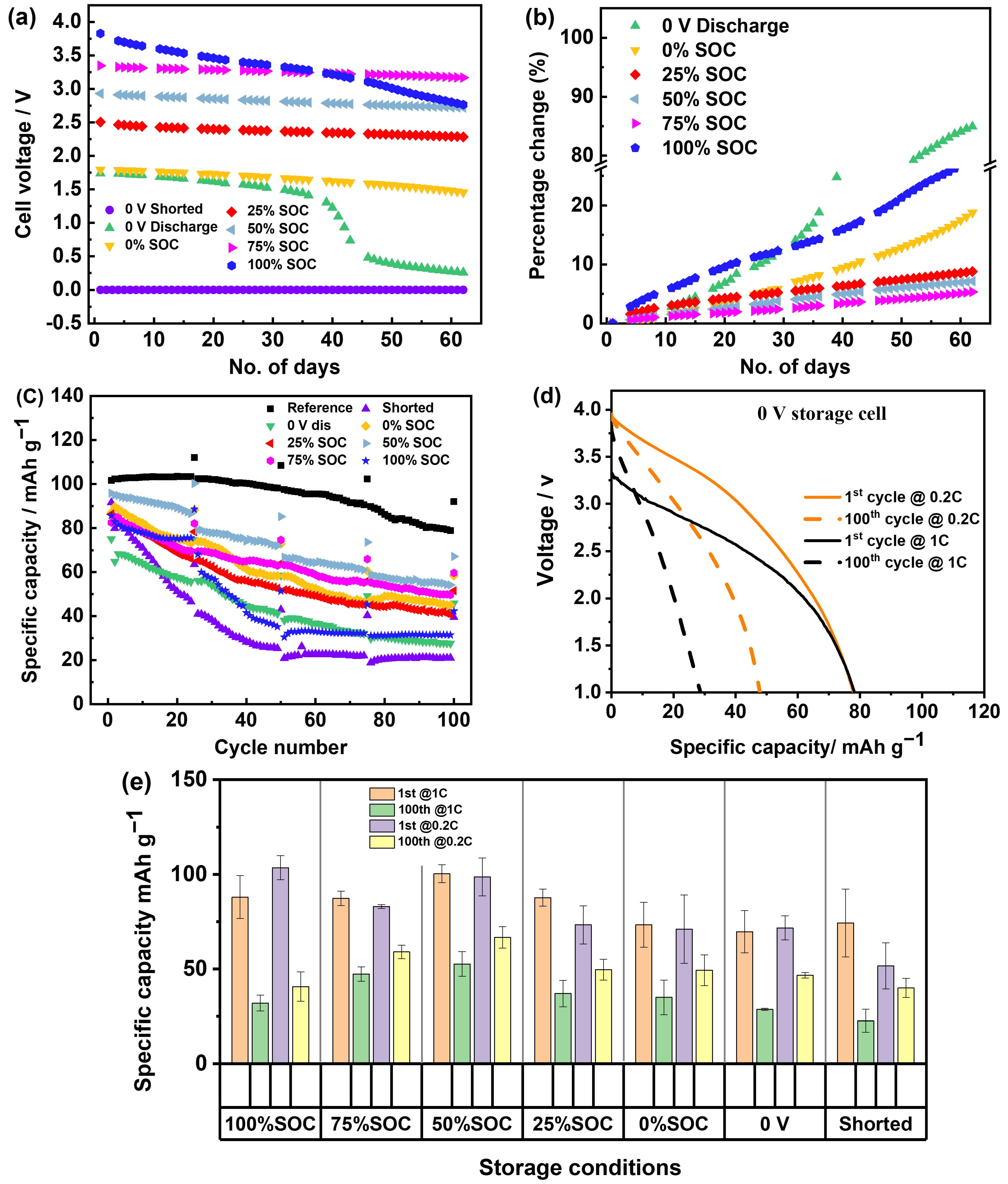
  • Influence of current density: Previous studies conducted cycling tests at a charge and discharge current of 1/3 C, whereas this study was performed at 1 C. Although intermittent use of a lower current (0.2 C) during the cycle confirmed that the rapid capacity attenuation is due to increased impedance during storage, the capacity retention rate of NMST//HC chemistry under low-current conditions remains unsatisfactory.
  • Influence of electrolyte: the electrolyte used in this study consists of EC:DEC in a 3:7 v/v% ratio, whereas the literature reports using an electrolyte composition of EC:DEC:PC in a 1:2:1 wt/wt ratio.
It should be noted here that different binder systems were used for the two chemistries. In the move to greater sustainability, non-toxic solvents and binders that provide a greater degree of recyclability are required. Therefore, water and water-soluble binder systems, such as CMC-SBR, are preferred. However, in the case of NMST, water was not possible due to degradation of the material. Details of the mixing, and powder and ink stability with PVDF-NMP have been previously published [25]. Previous work also shows that CMC-SBR and PVDF are stable to high voltages. SBR may decompose at about 4.3 V vs. Li/Li+ as shown previously with LiCoO2 [26]; however, only 3.8 V was reached in the case of PW in this work. The binder system on the cathode is unlikely to be the cause of self-discharge.
What is apparent is the crosstalk between the anode and cathode at a high state of charges. This has been observed in lithium-ion systems, [27] and mentioned in PW//HC systems previously [19]. SEI and cross-talk are highly dependent upon the electrolyte, and it is apparent that new electrolyte systems are needed for sodium-ion systems. Previous work with different electrolytes has shown that the SEI is unstable over time [28,29], and safety testing specifically showed that thermal runaway occurs more quickly in a sodium-ion system than lithium as the SEI dissolves at lower temperatures of around 26 °C [17]. For commonly used carbonated-based solvents, the EC:DME electrolyte system demonstrated lower capacity loss during storage compared to the EC:DEC electrolyte system [28]. Further research indicates that an electrolyte solution containing PC solvent appears to enhance the 0 V storage stability of NMST//HC chemistry [16].
Additives such as fluoroethylene carbonate (FEC) or difluoroethylene carbonate (DFEC) have been shown to be effective in improving the stability of the SEI component, thereby suppressing the self-discharge rate [29]. It is the subject of future work to understand the chemistry of the SEI, state of charge, and the electrolyte type and time.

Evaluation of Reconditioning after Storage on Cell Performance

It is hypothesized that the drop in open circuit voltage is caused by the dissolution of the SEI over time and the subsequent reaction of the sodiated hard carbon with the electrolyte, which results in a slow loss of sodium over time. This will be affected by temperature, and lower temperatures will reduce dissolution compared to higher temperatures. In previous work, it has been shown that the temperature at which the SEI dissolves is close to room temperature [18]. In this work, only room temperature storage close to the reported temperature for SEI dissolution in standard electrolytes was studied. After long storage conditions, it is, therefore, likely necessary to reform the interface layer, in a similar manner to lithium-ion batteries, which may change the availability of reversible sodium-ion content.
Three PW-HC cells were investigated after being discharged to 10% SOC or zero volts and stored at the OCV or short-circuited. EIS measurements before and after storage showed a significant increase in impedance as shown in Figure 4.
The increase in impedance makes us speculate that the formed solid electrolyte interphase (SEI) may have dissolved during the storage period and reformed poorly when cycled at higher currents. To confirm this, a reconditioning protocol was applied to the cells after 60 days of storage. Cells were reconditioned by using the same charge/discharge parameters as the formation process (0.1 C charge/discharge). Figure 5a1–c1 show the changes in impedance data for selected SOCs before and after the reconditioning process. Significant decreases in Rsf impedance after reconditioning were observed for the selected SOCs. Capacity and cycling stability were checked as well. The first discharge capacity at 1 C was increased from 103 to 105 mAh g−1 for the 0 V storage cells. After 100 cycles, the reversible capacity at 1 C was increased from 61 to 89 mAh g−1. The result indicates that reforming the cells after storage could help rebuild the SEI layer, thus leading to the recovery of lost capacity and improvement in cycling stability to some extent.

5. Conclusions

In this work, the impact of state of charge during long-term storage on the post-electrochemical performance of two sodium-ion configurations, namely Prussian//hard carbon and layered oxide//hard carbon, has been investigated. While storing cells at a zero state of charge or fully discharged to zero volts can reduce storage and post-processing risks, we have noted that storage at lower SOCs has a more detrimental effect on post-cycling stability due to SEI instability. A partial state of charge will give greater stability in terms of OCV decay during the storage period and subsequent cycling stability compared to a fully discharged state.
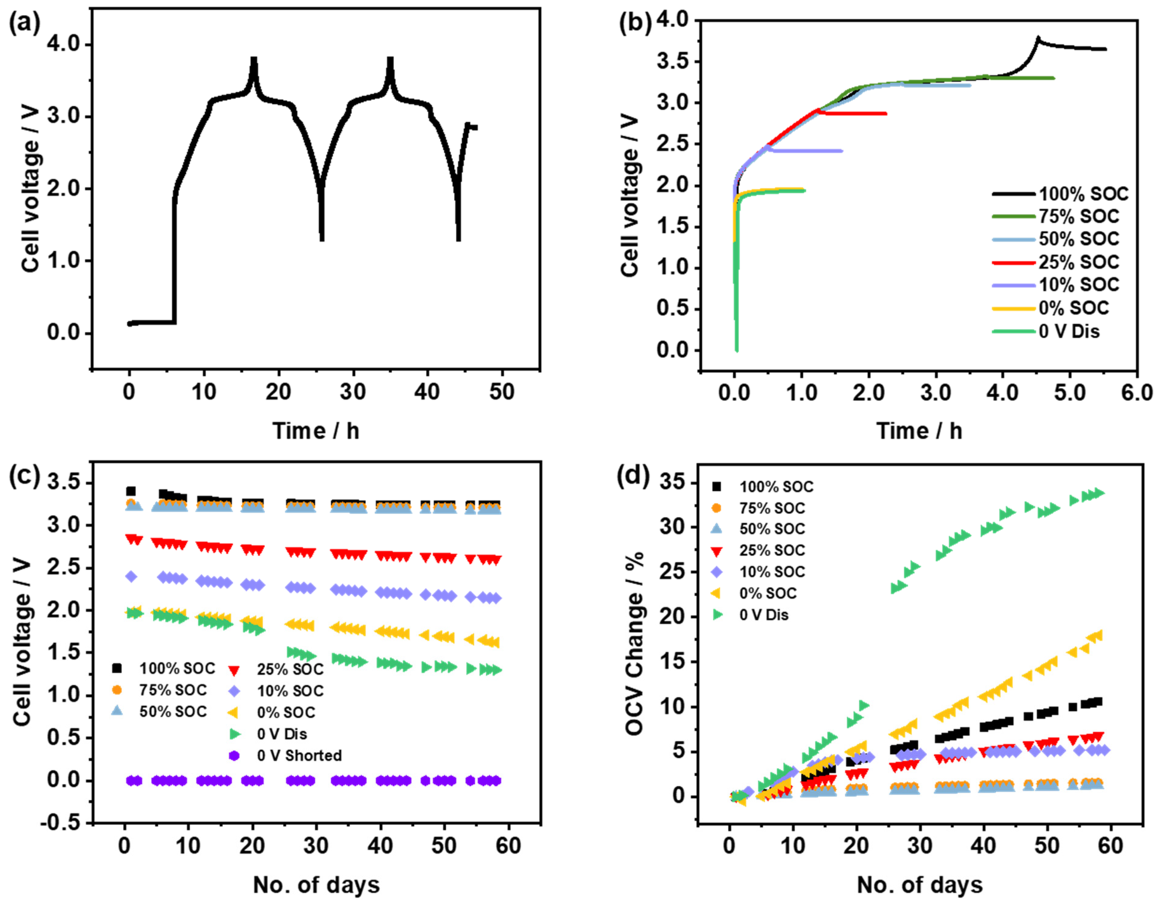
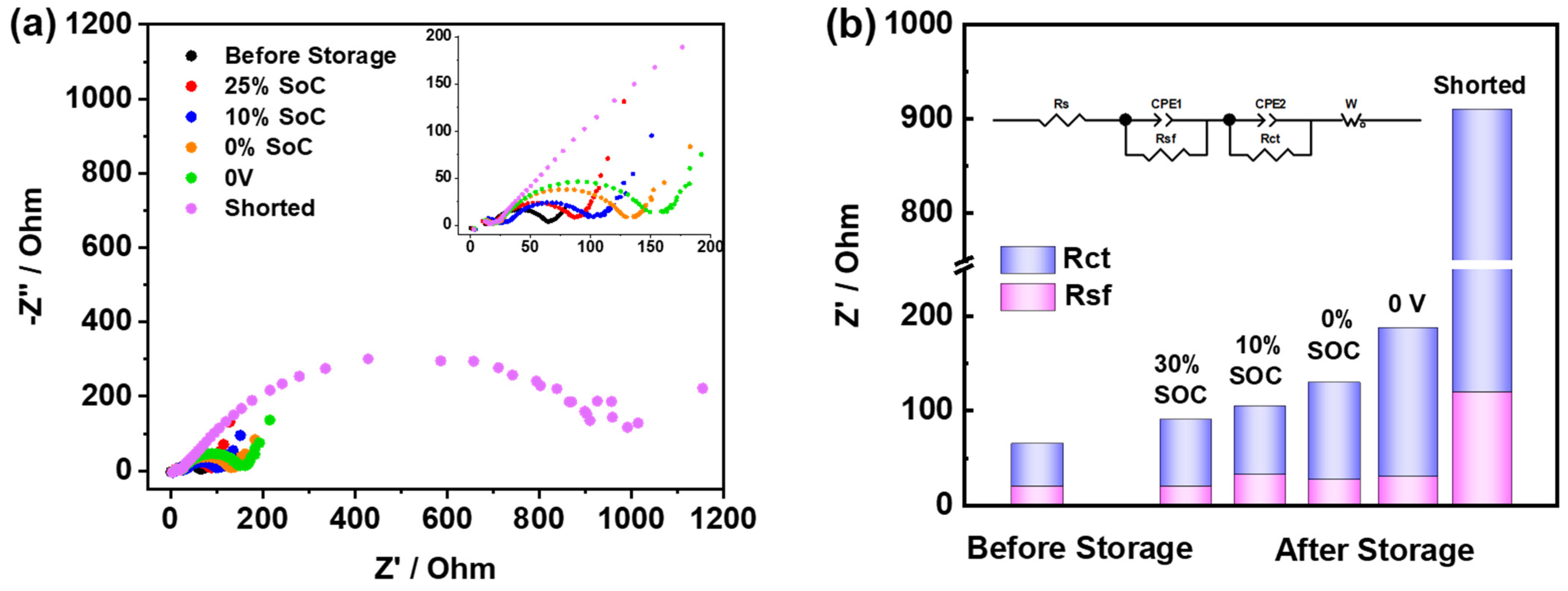
  • The 0 V, 0% SOC, and 100% SOC show great self-discharge or an OCV drop. These three examples also exhibit higher impedance and the poorest cycling stability when cycled after storage.
  • The 50% SOC and 75% SOC show the least OCV drop and exhibit cycling performance comparable to the reference cell (cell without storage).
  • For storage conditions below 30% SOC, which is interesting due to practical considerations for transport safety, 25% SOC shows relatively less degradation and acceptable post-cycling stability.
Storage at lower SOCs has more significant adverse effects on layered oxide-based Na-ion cells than those based on Prussian white. These results suggest that storage conditions need to be carefully selected, considering the full cell chemistry and duration of storage. For example, in terms of short transport, like air transportation, a zero state of charge is suggested here rather than a partial charge. But for long-term transport (such as sea transportation) or storage, partially charged states, in particular 25% SOC, are more appropriate. Additionally, a reformation protocol after long-term storage is recommended to rebuild the SEI, recover lost capacity, and improve cycling stability to some extent.
This research provides a guideline for sodium-ion batteries to be stored and shipped at an appropriate state of charge to minimise reduction in capacity and cycling stability. Further work is necessary to determine whether storing batteries at low temperatures, as opposed to room temperature, could prevent SEI dissolution when kept at a zero charge, thereby improving post-cycling stability.

Supplementary Materials

The following supporting information can be downloaded at https://www.mdpi.com/article/10.3390/batteries10100361/s1: Figure S1. Electrochemical characterization of PW cathode material and HC anode material in half cell. (a) Charge/discharge curves of PW in formation cycles at 10 mA g−1 and 2.0–4.0 V vs. Na/Na+; (b) cycling performance of PW at 100 mA g−1; (c) formation curves of commercial HC anode material at 10 mA g−1 and 0.01–2.0 V vs. Na/Na+, and (d) cycling performance of HC at 50 mA g−1. Figure S2. (a) Charge/discharge curves of NMST in formation cycles at 10 mA g−1 and 2.0–4.2 V vs. Na/Na+; (b) cycling performance of NMST at 100 mA g−1. (c) The voltage profile of NMST//HC full cells for the formation process, and (d) the voltage profiles for charging or discharging cells to various SOCs. Figure S3. (a) Voltage profiles of (a) PW//HC and (b) NMST//HC full cells in three-electrode cells using sodium metal as a reference electrode.

Author Contributions

Conceptualization, E.K. and B.K.; methodology, B.K. and T.S.; formal analysis, B.K., T.S., Y.L. and L.C.; investigation, T.S., B.K., Y.L. and L.C.; data curation, T.S., B.K. and Y.L.; writing—original draft preparation, T.S.; writing—review and editing, T.S., L.C., Y.L., E.K. and P.R.S.; visualization, T.S.; supervision, E.K.; project administration, E.K. and P.R.S.; funding acquisition, E.K. and P.R.S. All authors have read and agreed to the published version of the manuscript.

Funding

The authors thank the EU’s Horizon 2020-funded SIMBA project for funding (Grant agreement ID: 963542) and the Faraday Institution NEXGENNA project (FIRG064) and (EP/S003053/1) for support.

Data Availability Statement

The original contributions presented in the study are included in the article/Supplementary Materials; further inquiries can be directed to the corresponding author/s.

Conflicts of Interest

The authors declare no conflicts of interest.

References

  1. Bravo Diaz, L.; He, X.; Hu, Z.; Restuccia, F.; Marinescu, M.; Barreras, J.V.; Patel, Y.; Offer, G.; Rein, G. Review—Meta-Review of Fire Safety of Lithium-Ion Batteries: Industry Challenges and Research Contributions. J. Electrochem. Soc. 2020, 167, 090559. [Google Scholar] [CrossRef]
  2. Doughty, D.; Roth, E.P. A General Discussion of Li-Ion Battery Safety. Electrochem. Soc. Interface 2012, 21, 37–44. [Google Scholar] [CrossRef]
  3. Liu, K.; Liu, Y.; Lin, D.; Pei, A.; Cui, Y. Materials for Lithium-Ion Battery Safety. Sci. Adv. 2018, 4, eaas9820. [Google Scholar] [CrossRef] [PubMed]
  4. Bauer, A.; Song, J.; Vail, S.; Pan, W.; Barker, J.; Lu, Y. The Scale-up and Commercialization of Nonaqueous Na-Ion Battery Technologies. Adv. Energy Mater. 2018, 8, 1702869. [Google Scholar] [CrossRef]
  5. Rudola, A.; Rennie, A.J.R.; Heap, R.; Meysami, S.S.; Lowbridge, A.; Mazzali, F.; Sayers, R.; Wright, C.J.; Barker, J. Commercialisation of High Energy Density Sodium-Ion Batteries: Faradion’s Journey and Outlook. J. Mater. Chem. A Mater. 2021, 9, 8279–8302. [Google Scholar] [CrossRef]
  6. Huo, H.; Xing, Y.; Pecht, M.; Züger, B.J.; Khare, N.; Vezzini, A. Safety Requirements for Transportation of Lithium Batteries. Energies 2017, 10, 793. [Google Scholar] [CrossRef]
  7. IATA—Lithium Batteries Guidance Document. Available online: https://www.iata.org/en/programs/cargo/dgr/lithium-batteries/ (accessed on 21 September 2024).
  8. Zhao, M.; Kariuki, S.; Dewald, H.D.; Lemke, F.R.; Staniewicz, R.J.; Plichta, E.J.; Marsh, R.A. Electrochemical Stability of Copper in Lithium-Ion Battery Electrolytes. J. Electrochem. Soc. 2000, 147, 2874. [Google Scholar] [CrossRef]
  9. Maleki, H.; Howard, J.N. Effects of Overdischarge on Performance and Thermal Stability of a Li-Ion Cell. J. Power Sources 2006, 160, 1395–1402. [Google Scholar] [CrossRef]
  10. Roberts, S.; Kendrick, E. The Re-Emergence of Sodium Ion Batteries: Testing, Processing, and Manufacturability. Nanotechnol. Sci. Appl. 2018, 11, 23–33. [Google Scholar] [CrossRef]
  11. Rudola, A.; Sayers, R.; Wright, C.J.; Barker, J. Opportunities for Moderate-Range Electric Vehicles Using Sustainable Sodium-Ion Batteries. Nat. Energy 2023, 8, 215–218. [Google Scholar] [CrossRef]
  12. Tapia-Ruiz, N.; Armstrong, A.R.; Alptekin, H.; Amores, M.A.; Au, H.; Barker, J.; Boston, R.; Brant, W.R.; Brittain, J.M.; Chen, Y.; et al. 2021 Roadmap for Sodium-Ion Batteries. J. Phys. Energy 2021, 3, 031503. [Google Scholar] [CrossRef]
  13. Zhao, L.; Zhang, T.; Li, W.; Li, T.; Zhang, L.; Zhang, X.; Wang, Z. Engineering of Sodium-Ion Batteries: Opportunities and Challenges. Engineering 2023, 24, 172–183. [Google Scholar] [CrossRef]
  14. US11159027B2—Storage and/or Transportation of Sodium-Ion Cells—Google Patents. Available online: https://patents.google.com/patent/US11159027B2/en (accessed on 21 September 2024).
  15. Rudola, A.; Wright, C.J.; Barker, J. Reviewing the Safe Shipping of Lithium-Ion and Sodium-Ion Cells: A Materials Chemistry Perspective. Energy Mater. Adv. 2021, 2021, 9798460. [Google Scholar] [CrossRef]
  16. Desai, P.; Huang, J.; Foix, D.; Tarascon, J.M.; Mariyappan, S. Zero Volt Storage of Na-Ion Batteries: Performance Dependence on Cell Chemistry! J. Power Sources 2022, 551, 232177. [Google Scholar] [CrossRef]
  17. Robinson, J.B.; Finegan, D.P.; Heenan, T.M.M.; Smith, K.; Kendrick, E.; Brett, D.J.L.; Shearing, P.R. Microstructural Analysis of the Effects of Thermal Runaway on Li-Ion and Na-Ion Battery Electrodes. J. Electrochem. Energy Convers. Storage 2018, 15, 011010. [Google Scholar] [CrossRef]
  18. Qian, J.; Wu, C.; Cao, Y.; Ma, Z.; Huang, Y.; Ai, X.; Yang, H. Prussian Blue Cathode Materials for Sodium-Ion Batteries and Other Ion Batteries. Adv. Energy Mater. 2018, 8, 1702619. [Google Scholar] [CrossRef]
  19. Gourang Patnaik, S.; Escher, I.; Ferrero, G.A.; Adelhelm, P. Electrochemical Study of Prussian White Cathodes with Glymes—Pathway to Graphite-Based Sodium-Ion Battery Full Cells. Batter. Supercaps 2022, 5, e202200043. [Google Scholar] [CrossRef]
  20. Pfeifer, K.; Arnold, S.; Becherer, J.; Das, C.; Maibach, J.; Ehrenberg, H.; Dsoke, S. Can Metallic Sodium Electrodes Affect the Electrochemistry of Sodium-Ion Batteries? Reactivity Issues and Perspectives. ChemSusChem 2019, 12, 3312–3319. [Google Scholar] [CrossRef]
  21. Song, T.; Chen, L.; Gastol, D.; Dong, B.; Marco, J.F.; Berry, F.; Slater, P.; Reed, D.; Kendrick, E. High-Voltage Stabilization of O3-Type Layered Oxide for Sodium-Ion Batteries by Simultaneous Tin Dual Modification. Chem. Mater. 2022, 34, 4153–4165. [Google Scholar] [CrossRef]
  22. Conder, J.; Villevieille, C. How reliable is the Na metal as a counter electrode in Na-ion half cells? Chem. Commun. 2019, 55, 1275–1278. [Google Scholar] [CrossRef]
  23. Zheng, Y.; Wang, Y.; Lu, Y.; Hu, Y.S.; Li, J. A high-performance sodium-ion battery enhanced by macadamia shell derived hard carbon anode. Nano Energy 2017, 39, 489–498. [Google Scholar] [CrossRef]
  24. Chen, X.; Zheng, Y.; Liu, W.; Zhang, C.; Li, S.; Li, J. High-performance sodium-ion batteries with a hard carbon anode: Transition from the half-cell to full-cell perspective. Nanoscale 2019, 11, 22196–22205. [Google Scholar] [CrossRef] [PubMed]
  25. Roberts, S.; Chen, L.; Kishore, B.; Dancer, C.E.J.; Simmons, M.J.H.; Kendrick, E. Mechanism of Gelation in High Nickel Content Cathode Slurries for Sodium-Ion Batteries. J. Colloid Interface Sci. 2022, 627, 427–437. [Google Scholar] [CrossRef] [PubMed]
  26. Yabuuchi, N.; Kinoshita, Y.; Misaki, K.; Matsuyama, T.; Komaba, S. Electrochemical Properties of LiCoO2 Electrodes with Latex Binders on High-Voltage Exposure. J. Electrochem. Soc. 2015, 162, A538–A544. [Google Scholar] [CrossRef]
  27. Harris, O.C.; Lee, S.E.; Lees, C.; Tang, M. Review: Mechanisms and Consequences of Chemical Cross-Talk in Advanced Li-Ion Batteries. J. Phys. Energy 2020, 2, 032002. [Google Scholar] [CrossRef]
  28. Ma, L.A.; Buckel, A.; Hofmann, A.; Nyholm, L.; Younesi, R. Fundamental Understanding and Quantification of Capacity Losses Involving the Negative Electrode in Sodium-Ion Batteries. Adv. Sci. 2024, 11, 2306771. [Google Scholar] [CrossRef]
  29. Mogensen, R.; Brandell, D.; Younesi, R. Solubility of the Solid Electrolyte Interphase (SEI) in Sodium Ion Batteries. ACS Energy Lett. 2016, 1, 1173–1178. [Google Scholar] [CrossRef]
Figure 1. Effect of storage conditions on the OCV change of PW//HC cells. (a) The voltage profile of PW//HC cells for the formation process in a voltage window of 1.3–3.8 V, and (b) the voltage profiles for charging or discharging the cells to various SOCs. (c) The change in OCV of the cells over 60 days, and (d) the change in the OCV plotted as a percentage change.
Batteries 10 00361 g001
Figure 2. Effect of storage conditions on the post-cycling performance of PW//HC cells. (a) Cycling data for cells subjected to 60 days of storage. (b) Voltage profiles of the 0 V stored cell when discharged at 0.2 C and 1 C, respectively. (c) Comparison of capacity changes with cycling when discharged at 1 C and 0.2 C, respectively.
Batteries 10 00361 g002
Figure 3. Nyquist plots of (a) EIS changes after storage of PW//HC cells. (b) Comparison of fitted impedance before and after storage.
Batteries 10 00361 g003
Figure 4. Effect of storage conditions on NMST//HC cells as shown by (a) the changes in OCV of cells over 60 days of storage and (b) the change in OCV plotted as a percentage change. (c) Post-cycling performance after storage. (d) Voltage profiles of the 0 V stored cell when discharged at 0.2 C and 1 C, respectively. (e) Comparison of capacity changes with cycling when discharged at 1 C and 0.2 C, respectively.
Batteries 10 00361 g004
Figure 5. Comparison of impedance change and cycling performance with and without reconditioning after storage; (a1,a2) cell storage at 10% SOC; (b1,b2) cell storage at 0 V; (c1,c2) cell storage in a shorted state.
Batteries 10 00361 g005
Disclaimer/Publisher’s Note: The statements, opinions and data contained in all publications are solely those of the individual author(s) and contributor(s) and not of MDPI and/or the editor(s). MDPI and/or the editor(s) disclaim responsibility for any injury to people or property resulting from any ideas, methods, instructions or products referred to in the content.

