Abstract
KOH-based electrolytes with different salt additives were investigated to reduce their corrosive nature toward Mg/Ni metal hydride alloys used as negative electrodes in nickel metal hydride (Ni/MH) batteries. Alkaline metal halide salts and oxyacid salts were studied as additives to the traditional KOH electrolyte with concentrations varying from 0.005 M to 1.77 M. Effects of the cations and anions of the additives on charge/discharge performance are discussed. The reduction potential of alkaline cations and radii of halogen anions were correlated with initial capacity and degradation of the metal hydride alloy. A synergistic effect between KOH and some oxyacid salt additives was observed and greatly influenced by the nature of the salt additives. It was suggested that both the formation of a solid film over the metal hydride surface and the promotion of proton transfer in the additives containing electrolytes led to a decreased degradation of the electrodes and an increased discharge capacity. 12 salt additives, NaC2H3O2, KC2H3O2, K2CO3, Rb2CO3, Cs2CO3, K3PO4, Na2WO4, Rb2SO4, Cs2SO4, NaF, KF, and KBr, were found to increase the corrosion resistance of the MgNi-based metal hydride alloy.
1. Introduction
Nickel metal hydride (Ni/MH) batteries are currently one of the most widely used energy storage devices with many applications including hybrid electric vehicles, vacuum cleaners, electric toys, power tools, cordless phones, etc. [,]. They have many advantages such as having a high specific power, excellent tolerance to abuse, long cycle life, wide temperature operation range, and low self-discharge. Facing competition from Li-ion batteries, scientists continue to improve the various properties of Ni/MH batteries. One of the key areas demanding immediate attention is the gravimetric energy density.
A basic Ni/MH battery consists of an assembly of a highly conductive electrolyte, a metal hydride (MH) negative electrode, and a nickel hydroxide positive electrode. The cell reactions on the electrodes are shown in following equations:
Negative electrode: M + H2O + e− ⇌ OH− + MH
Positive electrode: Ni(OH)2 + OH− ⇌ NiOOH + H2O + e−
The most widely used electrolytes are pure KOH aqueous solutions with concentrations in the range of 20–36 wt% because these solutions are highly conductive and can efficiently convey protons in an electric field. AB5 and A2B7 type MH alloys with electrocapacity in the range of 300–350 mAh·g−1 have been commercialized as the negative electrodes for a long time. For the positive electrode, β-Ni(OH)2 co-precipitated with Co and Zn with an energy density of about 240 mAh·g−1 is the most commonly used material.
During charge, a negative voltage (with respect to the counter electrode) is applied to the MH electrode, and electrons enter the metal through the current collector to neutralize the protons produced from the splitting of water that occurs at the metal/electrolyte interface. During discharge, protons in the MH leave the surface and recombine with OH− in the alkaline electrolyte to form H2O and the resulting charge neutrality pushes the electrons out of the MH through the current collector, performing electrical work in the outer circuitry. Due to their demanding applications in Ni/MH batteries, MH alloys are required to possess a high capacity and moderate hydride stability. Iwakura et al. [] and Geng et al. [] tested the pressure-composition-temperature (P-C-T) isotherm curves of MH alloys, and correlated the hydrogen content with electrochemical potential through the Nernst equation. It was found that higher hydrogen content of alloys lead to higher electrochemical capacity. A wide set of hydrogen storage electrode alloys, other than AB5 and A2B7 type, have been reported to contain high hydrogen content and high electrochemical capacity. Among them, MgNi-based amorphous and nanocrystalline MH alloys are reported to have higher capacity than those in AB5 and A2B7 [,]. For example, Young and Nei [] reported that the theoretical capacity of MgNi metal alloys is about 1080 mAh·g−1 and Anik et al. [] reported that the practical electrocapacity values of MgNi and Mg0.9M0.1Ni (M = B, Ti, and Zr) type alloys are up to 495 mAh·g−1 and 508 mAh·g−1, respectively. The theoretical capacities of Mg80Sc20, Mg80Ti20, Mg80V20, and Mg80Cr20 reach 1790, 1750, 1700, and 1270 mAh·g−1, respectively. High hydrogen storage capacity, light weight, and the low cost of Mg type alloys make them one of the most promising commercially viable materials for high capacity Ni/MH batteries.
However, as many researchers have stated, MgNi-based electrodes are still far from commercial application because of the rapid decay of electrochemical capacity. Rongeat et al. [] reported a 70% decay in capacity after 20 charge/discharge cycles. A lot of effort has been put into increasing the corrosion resistance of MgNi-based alloys to KOH electrolytes, mostly through studying various types of substitutions in the MgNi formula, such as replacements of the A- (by rare earth, transition, or other metals []) and B-sites (by transition metals [,]), different fabrication procedures [], and surface treatment [].
It is well known that the use of electrolyte additives is one of the most economic and effective methods to improve the performance of electrodes as they do not affect the gravimetric and volumetric energy density of the battery. However, there are only a few studies of the modification of traditional KOH electrolytes to improve the cycle life of Ni/MH batteries. For example, Danczuk et al. [] and Karwowska et al. [] studied the effects of alkaline cation additives in KOH electrolyte to AB5 type alloys; Shangguan et al. [] found that Na2WO4 additives could increase the high temperature performance of Ni electrodes; Vaidyanathan et al. [] reported that KSiO4 and KNO3 additives could increase the end-of-charge voltage for Ni/MH batteries. Until now, very few studies for electrolyte additives’ effects to MgNi-based Ni/MH batteries have been reported. In this study, a systematic investigation on the effect of salt additives to the performance of traditional KOH electrolyte to an Mg52Ni39Co3Mn6 alloy prepared by the melt-spin and consequently mechanical alloying is performed. The experiment is accomplished by partially replacing KOH in the traditional electrolyte with salt additives while keeping the total ionic concentrations the same; thus, a better understanding of the effect of the anion and cation substitute of KOH electrolyte in Ni/MH battery can be obtained. The ultimate objective of this study is to develop a novel salt containing electrolyte formulation, which is as highly conductive as the traditional KOH electrolyte, but less corrosive to MgNi-based negative electrodes. With this new electrolyte, MgNi-based NiMH battery is expected to have the same, or even higher, electrochemical capacity and improved capacity stability compared to the traditional 30 wt% KOH electrolyte. The mechanism for proton transfer and improved corrosion resistance is also briefly discussed in this work.
2. Experimental
2.1. Materials and Electrolyte Matrix
The MgNi alloy (Mg52Ni39Co3Mn6) was provided by BASF/Battery Materials-Ovonic, Rochester Hills, MI, USA. The alloy was prepared by melt-spin followed by mechanical alloying. Details of the alloy preparation were described elsewhere []. Sintered β-Ni(OH)2 was also obtained from BASF/Battery Materials-Ovonic. The matrix examined on the effects of salt additives in aqueous KOH solution consisted of the following: (1) alkaline salts, including LiCl, NaCl, KCl, RbCl, and CsCl (with salt concentrations at 0.44, 0.88, 1.33, and 1.77 M each and KOH concentrations change accordingly as 6.33, 5.88, 5.44, and 5.00 M, respectively, with the total ionic concentration kept at 6.77 M); (2) halogen containing salts including KF, KCl, KBr, and KI (with salt concentrations the same as previously mentioned); (3) oxyacid containing salts, including LiNO3, NaNO3, KNO3, RbNO3, CsNO3, K2CO3, Na2CO3, Cs2CO3, Rb2CO3, K3PO4, KIO4, Li2SO4, K2SO4, Na2SO4, Rb2SO4, Cs2SO4, LiCHO2, NaCHO2, KCHO2, CsCHO2, Na2WO4, NaC2H3O2, and KC2H3O2 (with salt concentration at 0.44 M and 6.33 M KOH each for LiNO3, NaNO3, KNO3, RbNO3,CsNO3, KIO4, LiCHO2, NaCHO2, KCHO2, CsCHO2, NaC2H3O2, and KC2H3O2; 0.29 M and 6.33 M KOH each for K2CO3, Na2CO3, Cs2CO3, Rb2CO3, Na2WO4; 0.005 M and 6.33 M KOH each for Li2SO4, K2SO4, Na2SO4, Rb2SO4, and Cs2SO4; and 0.22 M salt and 6.33 M KOH for K3PO4); (4) other salts, including NaF, LiBr, and NaBr with salt concentration at 0.44 M and 6.33 M KOH each. All salt additives were purchased from Sigma-Aldrich Company (St. Louis, MO, USA). Except for the SO42− containing electrolytes, the total ion concentration of all electrolytes is kept at 13.54 M.
2.2. Measurements and Calculations
Electrochemical charge/discharge cycling tests were performed with an Arbin BT2000 battery tester (Arbin Instrument, College Station, TX, USA) at room temperature. For the test cells, the positive electrode was the sintered β-Ni(OH)2 and the negative electrode was made from directly dry-compacting the MgNi-based Mg52Ni39Co3Mn6 alloy onto the Ni-expanded metal without using any binder. A hydrophilic nonwoven polyolefin was used as the separator. The cell was charged at 100 mA·g−1 for 5 h, and discharged first at 100 mA·g−1 to reach a cut-off voltage fixed at 0.9 V. This is followed by resting for 30 s and the voltage will be recovered to a higher value, and then discharged at 24 mA·g−1 to reach a cut-off voltage fixed at 0.9 V. The process is repeated by a final discharge at 8 mA·g−1 to 0.9 V. The conductivity of the electrolyte was analyzed by an YSI model 3200 conductivity meter with a probe produced by Traceable VWR Inc. (West Chester, PA, USA). Cell is considered failed when its capacity drops below 70% of the initial capacity before cycling.
Three parameters: conductivity, discharge capacity, and degradation, were measured and compared to those with traditional 30% KOH electrolyte. Each test was repeated three times. Degradation was determined as the percent capacity loss per cycle within the initial 10 cycles, as shown in the following:
where:
- Caphigh is the highest value of discharge capacity in the initial 10 cycles;
- Caplow is the lowest value of discharge capacity in the initial 10 cycles;
- nhigh is the cycle number of the highest discharge capacity in the initial 10 cycles;
- nlow is the cycle number of the lowest discharge capacity in the initial 10 cycles;
- Subscript 0 is for 6.77 M (30%) KOH electrolyte.
3. Results and Discussion
3.1. Electrochemical Performance of MgNi-Based NiMH with 30% KOH Electrolyte
The cycle stability and capacity/degradation as functions of KOH concentration of negative electrode composed of Mg52Ni39Co3Mn6 MH alloy in a traditional 30% KOH electrolyte are shown in Figure 1 and Figure 2, respectively. This composition is selected due to its weak resistance to corrosion in traditional alkaline electrolyte, which allows for a better comparison of the effectiveness of additives. Other MgNi MH alloy compositions with high capacities and better cycle stability in 30% KOH are also available but were not used in this work. Figure 1 depicts the discharge capacities of Mg52Ni39Co3Mn6 in the first 10 cycles at five different KOH concentrations: 6.77, 6.33, 5.88, 5.44, and 5.00 M. It shows a rapid decay of discharge capacity in the first four cycles for all KOH concentrations and the capacity loss is more than 80% after 10 cycles. This result is consistent with other reported MgNi-based MH alloys []. Figure 2 shows the normalized capacity and degradation as functions of KOH concentration. A low KOH concentration corresponds to a low degradation; however, a low discharge capacity as well. Therefore, it is necessary to balance the degradation and discharge capacity of negative electrode by a matrix of salt additives.
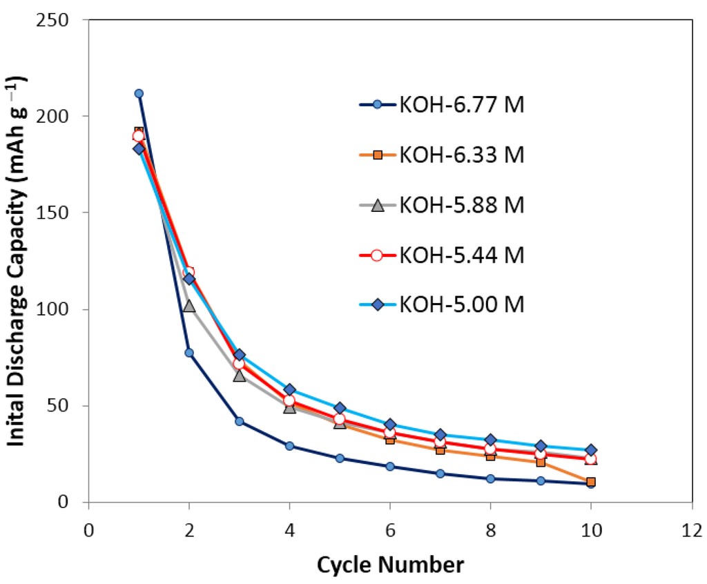
Figure 1.
Initial discharge capacity of pure KOH solutions in initial 10 cycles. KOH concentrations are 6.77 M, 6.33 M, 5.88 M, 5.33 M, and 5.00 M separately. It shows a decay of discharge capacity for more than 80% after 10 cycles’ running for all the pure KOH electrolytes.
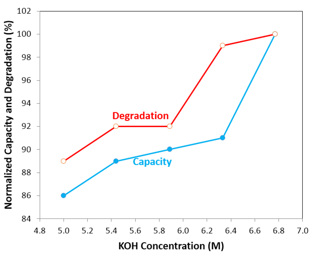
Figure 2.
Capacity and degradation of pure KOH electrolytes vs. KOH concentration. It shows at low KOH concentration, electrolyte has low degradation but low discharge capacity; at high KOH concentration, electrolyte has a high discharge capacity but high degradation.
3.2. Electrochemical Performance of Pure Salt Solutions
The conductivity, capacity, and degradation characteristics of KOH and various pure salt solutions are shown in Table 1. For a 6.77 M KOH electrolyte, the cells were cycled for more than 20 cycles with the total charging/discharging time of more than 130 h before cell failure. However, most of the cells with pure salt solutions as electrolyte totally lost activity within the first few cycles. For example, the cells with a 1.77 M LiCl solution lost all electrochemical activity only after five cycles. The cells were disassembled after the test and both the MgNi-based MH alloy and nickel hydroxide electrodes were found to be heavily corroded. Table 1 also shows that the conductivities of pure salt solutions are less than 20% of the conductivity of 6.77 M KOH electrolytes. Low conductivities could cause a low electronic efficiency for Ni/MH battery systems. Most of the pure salt solutions have a higher degradation compared to KOH, as shown in Table 1. While some salt solutions such as KF and RbCl resulted in a lower degradation, their capacities decreased significantly, which can be attributed to low electronic efficiencies. Table 1 indicates that all of the pure salt solutions were more corrosive to the electrodes than the standard KOH solution and are therefore unsuitable as electrolytes for Ni/MH systems.

Table 1.
Test time, test cycles, capacity, degradation and conductivity of pure 6.77 M KOH solution, pure 1.77 M salt solutions. The salts include KF, KCl, KBr, KI, LiCl, NaCl, KCl, RbCl, and CsCl. Note that the high corrosion could be observed in pure salt solutions.
| Salt | Concentration in M | Test time before cell failed in h | Test cycles before cell failed | Capacity % 1 | Degradation % 2 | Conductivity % 3 |
|---|---|---|---|---|---|---|
| KOH | 6.77 | >130 | >20 | 100.0 | 100.0 | 100.0 |
| KF | 1.77 | 105 | 20 | 12.3 | 49.4 | 12.9 |
| KCl | 1.77 | 73 | 8 | 79.7 | 136.5 | 14.6 |
| KBr | 1.77 | 56 | 4 | 167.4 | 309.9 | 12.9 |
| KI | 1.77 | 128 | 20 | 16.3 | n/a | 15.0 |
| LiCl | 1.77 | 56 | 5 | 84.7 | 185.4 | 10.3 |
| NaCl | 1.77 | 100 | 11 | 100.0 | 121.2 | 12.0 |
| KCl | 1.77 | 73 | 8 | 79.7 | 136.5 | 14.6 |
| RbCl | 1.77 | 70 | 9 | 82.8 | 88.8 | 15.0 |
| CsCl | 1.77 | 42 | 4 | 79.4 | 105.0 | 14.2 |
1: test error for capacity is 10%; 2: test error for degradation is 10%; 3: test error for conductivity is 5%.
3.3. Electrochemical Performance of Mixtures of Salt and KOH Solutions
3.3.1. Effect of Salt Additives on Conductivity
Traditionally, the concentration of KOH used in commercial Ni/MH batteries varies from 4.1 M to 8.5 M. Thus, the conductivities of KOH electrolytes with concentrations of 4.15, 4.65, 5.15, 5.67, 6.21, 6.77, 7.33, 7.91, and 8.52 M were tested. If we normalize the conductivities to the conductivity of 6.77 M KOH electrolyte as 100%, the conductivities of each of the electrolytes varied from 88% to 100%, as shown in Table 2.
Table 2.
Conductivity of traditional KOH electrolyte with concentration varies from 20 wt% to 36 wt%. Note the conductivities vary from 88% to 100%.
| Sample number | KOH concentration in M | Normalized conductivity in % 1 |
|---|---|---|
| 1 | 4.15 | 88.2 |
| 2 | 4.64 | 92.6 |
| 3 | 5.15 | 95.6 |
| 4 | 5.67 | 98.5 |
| 5 | 6.21 | 98.5 |
| 6 | 6.77 | 100.0 |
| 7 | 7.33 | 95.6 |
| 8 | 7.91 | 92.6 |
| 9 | 8.52 | 89.7 |
1: test error for normalized conductivity is 5%.
Electrolytes containing 6.33 M KOH and 32 types of salt additives were prepared and their conductivities were tested and shown in Table 3. It was found that the conductivities of all the additive-containing electrolytes vary from 88% to 100%. It shows that the salt containing electrolytes can be as conductive as traditional KOH electrolytes in some cases (KIO4 and KNO3).
Table 3.
Conductivity and concentration of additive containing electrolyte. Note the conductivities vary from 88% to 100%.
| Salt | Concentration in M | Conductivity in % 1 | Salt | Concentration in M | Conductivity in % 1 | Salt | Concentration in M | Conductivity in % 1 |
|---|---|---|---|---|---|---|---|---|
| LiCl | 0.44 | 97.4 | Na2WO4 | 0.29 | 88.3 | Li2SO4 | 0.005 | 90.7 |
| NaCl | 0.44 | 97.4 | KIO4 | 0.44 | 100.0 | Na2SO4 | 0.005 | 91.4 |
| KCl | 0.44 | 97.0 | LiNO3 | 0.44 | 97.7 | K2SO4 | 0.005 | 89.0 |
| RbCl | 0.44 | 96.3 | NaNO3 | 0.44 | 97.7 | Rb2SO4 | 0.005 | 89.3 |
| CsCl | 0.44 | 96.3 | RbNO3 | 0.44 | 95.5 | Cs2SO4 | 0.005 | 88.7 |
| KF | 0.44 | 96.8 | KNO3 | 0.44 | 100 | LiCHO2 | 0.44 | 92.4 |
| KBr | 0.44 | 98.3 | K2CO3 | 0.29 | 99.6 | KCHO2 | 0.44 | 93.6 |
| KI | 0.44 | 96.1 | Cs2CO3 | 0.29 | 97.0 | CsCHO2 | 0.44 | 94.1 |
| LiBr | 0.44 | 93.8 | Rb2CO3 | 0.29 | 98.5 | KC2H3O2 | 0.44 | 89.4 |
| NaBr | 0.44 | 94.5 | Na2CO3 | 0.29 | 89.0 | NaC2H3O2 | 0.44 | 90.5 |
| NaF | 0.44 | 96.9 | K3PO4 | 0.22 | 99.2 | - | - | - |
1: test error for conductivity is 5%.
3.3.2. Effect of Salt Additives on Discharge Capacity and Degradation
Figure 3 shows the effects of the salt additive containing electrolytes on the discharge capacity and degradation. Data are normalized to the degradation and discharge capacity of 6.77 M KOH. Figure 3 can be divided into four different areas depending on the degradation and capacity.
Area 1: normalized degradation <100% and normalized capacity >100%. The electrolytes in this area are the most desirable since they offer lower degradations with improved capacities. It includes NaC2H3O2 (0.44 M and 6.33 M KOH solution), KC2H3O2 (0.44 M and 6.33 M KOH solution), K2CO3 (0.29 M and 6.33 M KOH, 0.59 M and 5.88 M KOH, 0.89 M and 5.44 M KOH solutions), Rb2CO3 (0.29 M and 6.33 M KOH solution), Cs2CO3 (0.29 M and 6.33 M KOH solution), K3PO4 (0.22 M and 6.33 M KOH, 0.44 M and 5.88 M KOH, 0.66 M and 5.44 M KOH, 0.88 M and 5 M KOH solutions), NaF (0.44 M and 6.33 M KOH solution), KF (0.44 M and 6.33 M KOH, 0.88 M and 5.88 M KOH solutions), NaBr (0.44 M and 6.33 M KOH solution), Rb2SO4 (0.005 M and 6.33 M KOH solution), Cs2SO4 (0.005 M and 6.33 M KOH solution), KBr (0.44 M and 6.33 M KOH solution), LiBr (0.44 M and 6.33 M KOH solution), and RbCl (0.88 M and 5.88 M KOH solution).
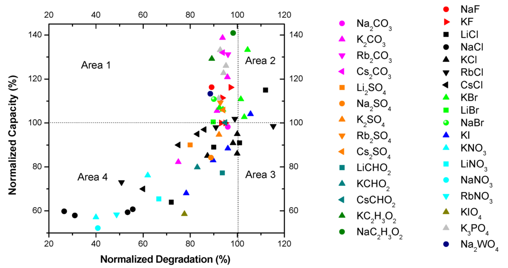
Figure 3.
Screen test results of discharge capacity and degradation for the electrolytes containing various salt additives.
Area 2: normalized degradation >100% and normalized capacity >100%. This area contains electrolytes with chemical activity which increase both the capacity and the degradation of the MgNi-based MH alloy. KBr (0.88 M and 5.88 M KOH, 1.33 M and 5.44 M KOH, 1.77 M and 5 M KOH solutions), LiCl (0.44 M and 6.33 M KOH solution), and KI (0.44 M and 6.33 M KOH solution) are examples.
Area 3: normalized degradation >100% and normalized capacity <100%. It includes RbCl (1.33 M and 5.44 M KOH solution), LiCl (0.88 M and 5.88 M KOH solution), and KCl (0.44 M and 6.33 M KOH, 1.77 M and 5 M KOH solutions) and is the worst scenario with low capacities and high degradations.
Area 4: normalized degradation <100% and normalized capacity <100%. It contains additives with reduced chemical activity resulting in reduced capacity and degradation such as NaCl (0.44 M and 6.33 M KOH, 0.88 M and 5.88 M KOH, 1.33 M and 5.44 M KOH, 1.77 M and 5 M KOH solutions), KNO3 (0.44 M and 6.33 M KOH, 0.88 M and 5.88 M KOH solutions), RbNO3 (0.44 M and 6.33 M KOH solution), LiNO3 (0.44 M and 6.33 M KOH solution), NaNO3 (0.44 M and 6.33 M KOH solution), RbCl (0.44 M and 6.33 M KOH, 1.77 M and 5 M KOH solutions), LiCl (1.33 M and 5.44 M KOH, 1.77 M and 5 M KOH solutions), KI (0.88 M and 5.88 M KOH, 1.33 M and 5.44 M KOH, 1.77 M and 5 M KOH solutions), K2CO3 (1.77 M and 5 M KOH solution), KCHO2 (0.44 M and 6.33 M KOH solution), LiCHO2 (0.44 M and 6.33 M KOH solution), KCl (0.88 M and 5.88 M KOH, 1.33 M and 5.44 M KOH solutions), CsCl (0.44 M and 6.33 M KOH, 0.88 M and 5.88 M KOH, 1.33 M and 5.44 M KOH, 1.77 M and 5 M KOH solutions), K2SO4 (0.44 M and 6.33 M KOH solution), Na2SO4 (0.44 M and 6.33 M KOH solution), Na2CO3 (0.44 M and 6.33 M KOH solution), Li2SO4 (0.005 M and 6.33 M KOH solution), and CsCHO2 (0.44 M and 6.33 M KOH solution).
In order to gain a better understanding of the effects of the anions and cations of additive salts on the normalized discharge capacity and electrode degradation, the data in Figure 3 was further analyzed based on the anions and cations.
3.3.3. Performance of Alkaline Cations Containing Electrolytes
Figure 4 and Figure 5 illustrate the effects of alkaline cations (Li, Na, K, Rb, and Cs) on normalized degradation and discharge capacity, respectively, at 0.44 M of salt (with 6.33 M KOH), 0.88 M of salt (with 5.88 M KOH), 1.33 M of salt (with 5.44 M KOH), and 1.77 M of salt (with 5 M KOH). Figure 4 shows that degradation values vary from 26% to 115% with the addition of alkaline salts to traditional KOH electrolytes. CsCl and NaCl containing electrolytes decrease significantly in degradation compared to that in a pure KOH solution. At a low salt concentration (0.44 M salt with 6.33 M KOH), KCl containing electrolyte has a similar degradation value to KOH; LiCl containing electrolyte has an increased degradation, which is unfavorable; and RbCl electrolyte has a decreased degradation. At a high salt concentration (1.77 M salt with 5 M KOH), all electrolytes have a decreased degradation. Figure 5 illustrates that, except for NaCl containing electrolytes, the discharge capacity for electrolytes with a low salt concentration (0.44 M salt with 6.33 M KOH) is increased, while the discharge capacity for electrolytes with a high salt concentration (1.77 M salt with 5 M KOH) is greatly decreased. Figure 4 and Figure 5 show that the concentration of alkaline salt in electrolytes has a significant influence on the degradation and discharge capacity. A linear correlation between degradation and reduction potential of alkaline ions was found for electrolytes containing a low concentration of salt, shown in Figure 6. It suggests that degradation is influenced by the reducibility of the salt additive. There is no apparent relationship between capacity and reduction potential of alkaline metals. There is also no apparent relationship between degradation and reduction potential in the electrolytes with high salt concentration. It is supposed that the high concentration of salt would cause the effect of electrostatic interaction among ions to become stronger and influence the degradation performance.
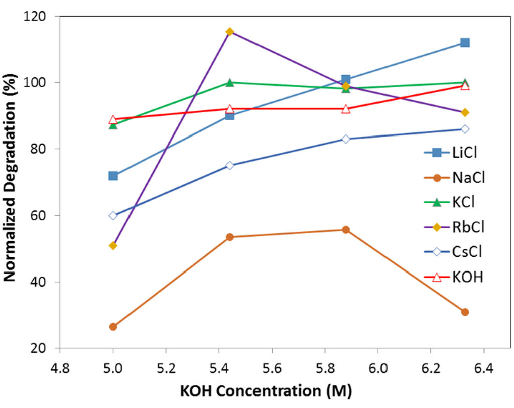
Figure 4.
Degradation of electrolyte with 6.33 M KOH (and 0.44 M salts), 5.88 M KOH (and 0.88 M salts), 5.44 M KOH (and 1.33 M salts), 5.00 M KOH (and 1.77 M salts). Salts are LiCl, NaCl, KCl, RbCl, and CsCl, respectively.
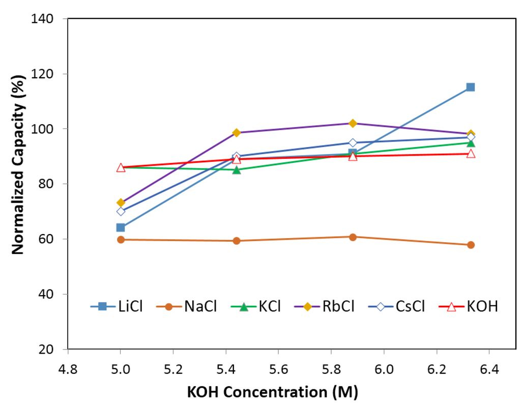
Figure 5.
Capacity of electrolyte with 6.33 M KOH (and 0.44 M salts), 5.88 M KOH (and 0.88 M salts), 5.44 M KOH (and 1.33 M salts), 5.00 M KOH (and 1.77 M salts). Salts are LiCl, NaCl, KCl, RbCl, and CsCl, respectively.
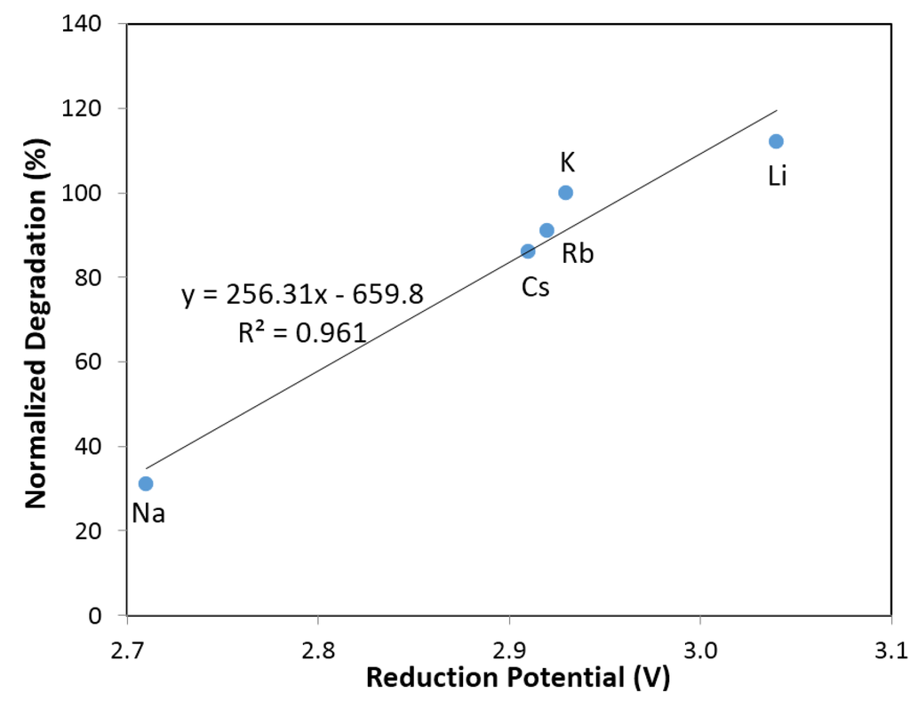
Figure 6.
Linear fit of degradation with reduction potential of alkaline ions (Li+, Na+, K+, Rb+ and Cs+).
3.3.4. Performance of Halogen Containing Electrolytes
Figure 7 and Figure 8 illustrate the effects of anions (F, Cl, Br and I) on normalized degradation and discharge capacity, respectively, with 0.44 M of salt (with 6.33 M KOH), 0.88 M of salt (with 5.88 M KOH), 1.33 M of salt (with 5.44 M KOH), and 1.77 M of salt (with 5 M KOH). Figure 7 illustrates that the normalized degradation varies from 78% to 105%, which suggests that halogen ions’ effects on degradation is not as strong as those in alkaline ions’. Figure 7 also indicates that at low (0.44 M) and high salt concentrations (1.77 M), the additives slightly increase the degradation value except for the electrolyte with 0.44 M KF and 6.33 M KOH. Figure 8 illustrates that discharge capacity varies from 68% to 133%. At a low salt concentration (0.44 M salt and 6.33 M KOH), all salts boost the discharge capacity, and at a high salt concentration (1.77 M salt and 5 M KOH), only KF and KBr additives enhance the discharge capacity. Figure 7 and Figure 8 indicate that the concentration of salt additive in the electrolyte has a significant influence on the electrochemical performance. Figure 9 shows an apparent correlation between anion radii and the normalized degradation of low salt concentration electrolytes (0.44 M salt and 6.33 M KOH). This finding can also be explained by the energies of H–F, H–Cl, H–Br, and H–I bonds. In the traditional KOH electrolyte system, the OH group is an effective carrier for proton transfer between electrodes. In the salt containing electrolytes, both the OH groups and salt anions act as proton carriers. As F has a smaller radius than Cl, Br and I, its bond energy of H–F at 135 kcal·mol−1 is higher than that of O–H at 111 kcal·mol−1, H–Cl at 103 kcal·mol−1, H–Br at 87.5 kcal·mol−1, and H–I at 71 kcal·mol−1. The H–F bond is more stable than other hydrogen–halogen bonds during the charge/discharge process. Therefore, KF shows a decreased degradation compared to other potassium halogen salts. The bond energies of H–Cl, H–Br, and H–I are less than O–H, which implies that in KCl, KBr, and KI containing electrolytes, the OH− group is preferred as the proton accepter instead of Cl−, Br− and I−. Thus, KCl, KBr, and KI containing electrolytes (with a low salt concentration) show a higher degradation than the traditional KOH electrolyte.
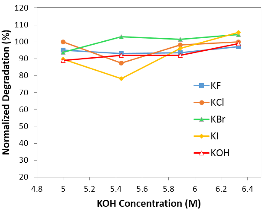
Figure 7.
Degradation of electrolyte with 6.33 M KOH (and 0.44 M salts), 5.88 M KOH (and 0.88 M salts), 5.44 M KOH (and 1.33 M salts), 5.00 M KOH (and 1.77 M salts). Salts are KF, KCl, KBr, and KI, respectively.
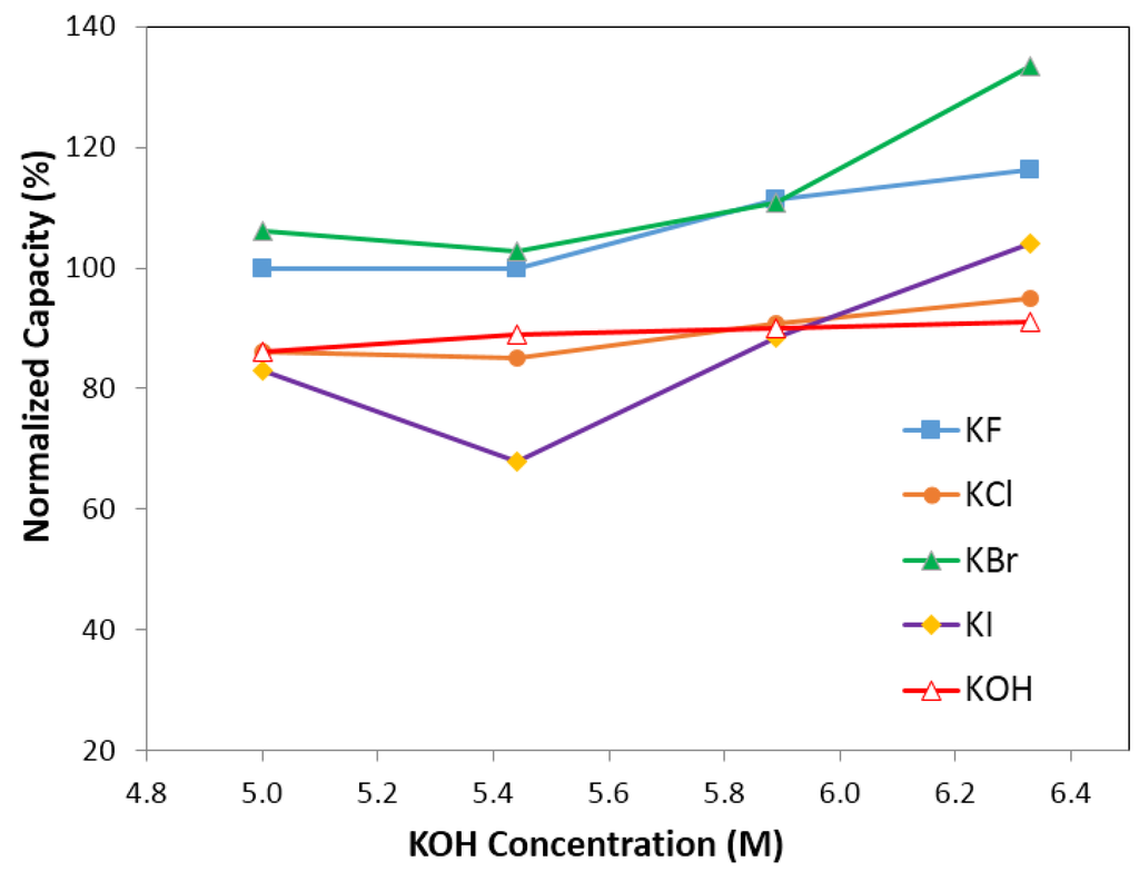
Figure 8.
Capacity of electrolyte with 6.33 M KOH (and 0.44 M salts), 5.88 M KOH (and 0.88 M salts), 5.44 M KOH (and 1.33 M salts), 5.00 M KOH (and 1.77 M salts). Salts are KF, KCl, KBr, and KI, respectively.
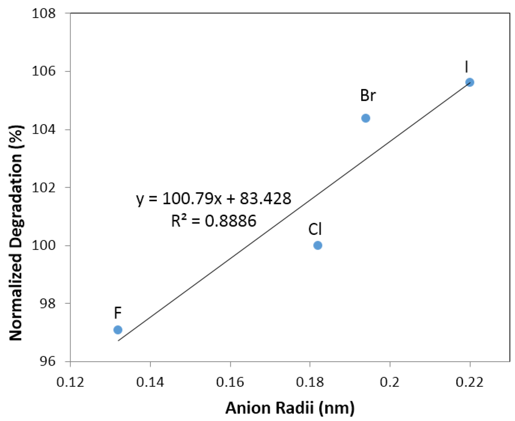
Figure 9.
Linear fit of degradation with halogen anion radii (F−, Cl−, Br−, and I−).
3.3.5 Performance of Oxyacid Containing Electrolytes
Effects of low oxyacid salt concentration (and 6.33 M KOH) electrolytes on normalized discharge capacity and degradation are shown in Figure 10. Unlike halogen salt additives and alkaline salt additives, all oxyacid salt additives satisfy the desired properties of degradation <100%, and distribute only in Areas 1 and 4. The electrolytes in Area 1 (i.e., normalized degradation <100% and normalized discharge capacity >100%) include: NaC2H3O2 (0.44 M additives and 6.33 M KOH), KC2H3O2 (0.44 M additives and 6.33 M KOH), K2CO3 (0.29 M additives and 6.33 M KOH), Rb2CO3 (0.29 M additives and 6.33 M KOH), Cs2CO3 (0.29 M additives and 6.33 M KOH), K3PO4 (0.22 M additives and 6.33 M KOH), Na2WO4 (0.29 M additives and 6.33 M KOH), Rb2SO4 (0.005 M additives and 6.33 M KOH), Cs2SO4 (0.005 M additives and 6.33 M KOH). The electrolytes in Area 4 (i.e., normalized degradation <100% and normalized discharge capacity <100%) include: Rb2SO4 (0.005 M additives and 6.33 M KOH), Li2SO4 (0.005 M additives and 6.33 M KOH), Rb2SO4 (0.005 M additives and 6.33 M KOH), CsCHO2 (0.44 M additives and 6.33 M KOH), KNO3 (0.44 M additives and 6.33 M KOH), RbNO3 (0.44 M additives and 6.33 M KOH), LiNO3 (0.44 M additives and 6.33 M KOH), NaNO3 (0.44 M additives and 6.33 M KOH), K2CO3 (1.77 M additives and 5 M KOH), KCHO2 (0.44 M additives and 6.33 M KOH), LiCHO2 (0.44 M additives and 6.33 M KOH), K2SO4 (0.005 M additives and 6.33 M KOH), Na2SO4 (0.005 M additives and 6.33 M KOH), and Na2CO3 (0.44 M additives and 6.33 M KOH).
The trend of discharge capacity is NO3− < IO4− < CHO2− < SO42− < WO42− < CO32− < PO42− < C2H3O2−. As shown in references [,], all of the above oxyacid anions, except for NO3−, could react with Mg or Ni ions on the surface of the metal hydride to form a solid layer that covers the metal hydride particles, which could protect them from electrolyte corrosion. The solid layer covering the metal hydride particles had a significant influence on discharge capacity and degradation. Figure 11 illustrates the charge voltage curves of the first cycle of cells with electrolytes containing K2CO3, K3PO4, CsCO3, Rb2CO3, Na2WO4, NaC2H3O2, KC2H3O2, Rb2SO4, and Cs2SO4, which demonstrated normalized degradation <100% and discharge capacity >100%. The full charge voltage of these oxyacid salt electrolytes is slightly lower than that of traditional KOH electrolyte, which means the resistance of these additive containing electrolytes is lower than that of traditional KOH electrolytes. A lower voltage also implies less corrosion to the electrodes. The charge voltage curves of other salt additive containing electrolytes (in Areas 2, 3, and 4 in Figure 3) were also studied. The values of the first cycle full charge voltage were generally higher than that of KOH electrolyte (data not shown). Further research on the formation mechanism of solid layer and the effects of solid layer on corrosion resistance and electrochemical performance will be performed.
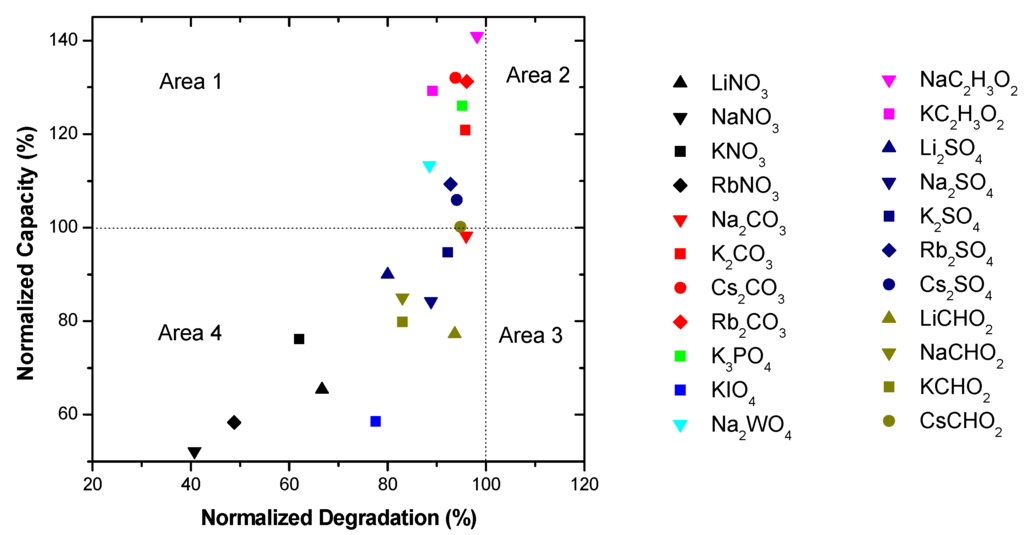
Figure 10.
Discharge capacity and degradation for electrolytes containing oxyacid salts, including NaC2H3O2, KC2H3O2, K2CO3, Rb2CO3, Cs2CO3, K3PO4, Rb2SO4, Cs2SO4, Rb2SO4, Li2SO4, Rb2SO4, CsCHO2, KNO3, RbNO3, LiNO3, NaNO3, K2CO3, KCHO2, LiCHO2, K2SO4, Na2SO4, and Na2CO3.
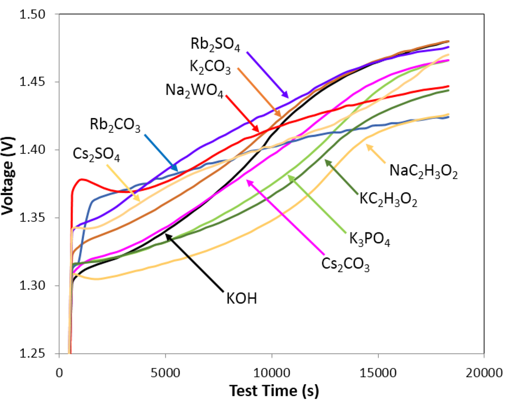
Figure 11.
Charge voltage curves for first circle of electrolytes containing 0.29 M K2CO3 and 6.33 M KOH, 0.29 M Cs2CO3 and 6.33 M KOH, 0.29 M Rb2CO3 and 6.33 M KOH, 0.29 M Na2WO4 and 6.33 M KOH, 0.44 M NaC2H3O2 and 6.33 M KOH, 0.44 M KC2H3O2 and 6.33 M KOH, 0.005 M Rb2SO4 and 6.33 M KOH, 0.005 M Cs2SO4 and 6.33 M KOH, 0.22 M K3PO4, and 6.33 M KOH. The final charge voltage of these oxyacid salt containing electrolytes is lower than traditional KOH electrolyte.
Figure 12 shows the effects of K2CO3 and K3PO4 containing electrolytes on the normalized discharge capacity and degradation. It was found that the concentration of oxyacid salts, similar to the concentration of halogen salts and alkaline salts, have a significant influence on electrochemical performance. There was a maximum value in discharge capacity for both 0.44 M K2CO3 and K3PO4 containing KOH electrolytes. On the other hand, the normalized degradation seemed to be stable for the concentration range of K2CO3 and K3PO4 studied, except for 0.89 M K2CO3 containing electrolytes which shows a lower normalized degradation.
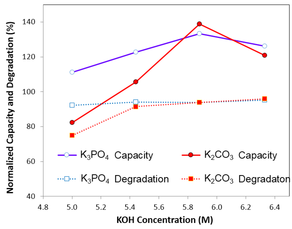
Figure 12.
Degradation and capacity of the electrolytes containing K2CO3 and K3PO4 separately. The solutions are: 6.33 M KOH and 0.29 M K2CO3, 5.88 M KOH and 0.59 M K2CO3, 5.44 M KOH and 0.89 M K2CO3, 5.00 M KOH and 1.18 M K2CO3; 6.33 M KOH and 0.22 M K3PO4, 5.88 M KOH and 0.44 M K3PO4, 5.44 M KOH and 0.66 M K3PO4, 5.00 M KOH, and 0.88 M K3PO4.
Since the electrolyte with 0.44 M Cs2CO3 and 6.33 M KOH shows good performance on MgNi metal alloy, it was selected to test two kinds of BCC/C14 type metal alloy (V44.0Ti15.6Ni18.5Cr11.6Mn6.9Hf2.1Co1.4Al0.4 and V44.0Ti15.6Ni18.5Cr11.6Mn6.9Zr2.1Co1.4Al0.4). The BCC/C14 metal alloy has high hydrogen storage ability and high theoretical discharge capacity, and is also considered as a strong candidate material for metal alloy electrode in NiMH batteries as the MgNi metal alloy [,]. The theoretical discharge capacity of MgNi alloy (Mg52Ni39Co3Mn6) was reported as 999 mAh·g−1 [,]. However, Figure 13 shows that the maximum value of practical discharge capacity in traditional 6.77 M KOH electrolyte over Mg52Ni39Co3Mn6 is only 212 mAh·g−1. When Mg52Ni39Co3Mn6 alloy electrode is tested in Cs2CO3 containing electrolyte, the maximum discharge capacity is 300 mAh·g−1, which suggests less corrosive in Cs2CO3 containing electrolyte. The theoretical discharge capacity of these two BCC/C14 alloys (V44.0Ti15.6Ni18.5Cr11.6Mn6.9Hf2.1Co1.4Al0.4 and V44.0Ti15.6Ni18.5Cr11.6Mn6.9Zr2.1Co1.4Al0.4) was reported as 767 mAh·g−1 []. In traditional 6.77 M KOH, the maximum capacity for V44.0Ti15.6Ni18.5Cr11.6Mn6.9Hf2.1Co1.4Al0.4 is only 348 mAh·g−1 and capacity decay after 86 cycles’ running is 78% and for V44.0Ti15.6Ni18.5Cr11.6Mn6.9Zr2.1Co1.4Al0.4, the maximum is 366 mAh·g−1 and capacity decay is 52%. In electrolyte of 0.44 M Cs2CO3 and 6.33 M KOH, the maximum capacity of V44.0Ti15.6Ni18.5Cr11.6Mn6.9Hf2.1Co1.4Al0.4 and V44.0Ti15.6Ni18.5Cr11.6Mn6.9Zr2.1Co1.4Al0.4 is 378 mAh·g−1. In addition, capacity decay of 100 cycles’ running for V44.0Ti15.6Ni18.5Cr11.6Mn6.9Hf2.1Co1.4Al0.4 is 33%, and for V44.0Ti15.6Ni18.5Cr11.6Mn6.9Zr2.1Co1.4Al0.4 is 30%. As stated above, traditional 6.77 M KOH is quite corrosive to metal alloys and leads to a very low practical discharge capacity. The Cs2CO3 salt additive slightly improves discharge capacity and tremendously decreases capacity decay on electrodes of Mg52Ni39Co3Mn6, V44.0Ti15.6Ni18.5Cr11.6Mn6.9Hf2.1Co1.4Al0.4 and V44.0Ti15.6Ni18.5Cr11.6Mn6.9Zr2.1Co1.4Al0.4 as shown in Figure 13.
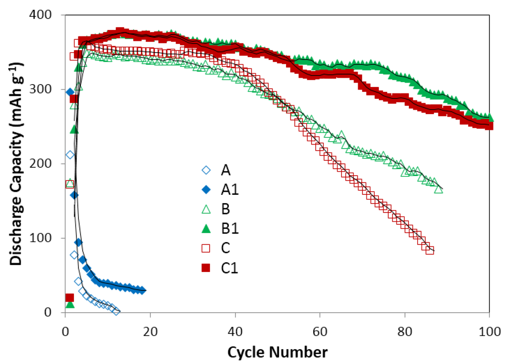
Figure 13.
Discharge capacity of Mg52Ni39Co3Mn6, V44.0Ti15.6Ni18.5Cr11.6Mn6.9Hf2.1Co1.4Al0.4 and V44.0Ti15.6Ni18.5Cr11.6Mn6.9Zr2.1Co1.4Al0.4 in electrolyte of 6.77 M KOH and electrolyte of 0.44 M Cs2CO3 and 6.33 M KOH. A: Mg52Ni39Co3Mn6 in 6.77 M KOH; B: V44.0Ti15.6Ni18.5Cr11.6Mn6.9Hf2.1Co1.4Al0.4 in 6.77 M KOH; C: V44.0Ti15.6Ni18.5Cr11.6Mn6.9Zr2.1Co1.4Al0.4 in 6.77 M KOH; A1: Mg52Ni39Co3Mn6 in 0.44 M Cs2CO3 and 6.33 M KOH; B1: V44.0Ti15.6Ni18.5Cr11.6Mn6.9Hf2.1Co1.4Al0.4 in 0.44 M Cs2CO3 and 6.33 M KOH; C1: V44.0Ti15.6Ni18.5Cr11.6Mn6.9Zr2.1Co1.4Al0.4 in 0.44 M Cs2CO3 and 6.33 M KOH. It shows Cs2CO3 salt additive slightly improves discharge capacity and tremendously decreases capacity decay.
3.4. Mechanistic Analysis for Using Additive Containing Electrolytes in Novel Ni/MH Battery Systems
3.4.1. Synergistic Effect between KOH and Salt Additives
Comparing additive containing electrolytes to the pure KOH and pure salt electrolytes, significant changes in degradation and discharge capacity were observed. For salts in Area 1 of Figure 3 (i.e., degradation <100% and capacity >100%), a synergistic effect between the salt additives and KOH electrolyte is presumed to explain the improvement in electro-performance. The synergistic effect can be explained by the following inferences: (1) a solid film forms on the surface of both electrodes. As shown in Figure 14, all the anions in Area 1 were able to react with Mg2+ and Ni2+ on the surface of MgNi metal hydride particles and Ni2+ on the surface of β-Ni(OH)2 particles to form a solid deposit [,]. In this research, discharge capacity is closely related to the amount of MgNi metal hydride in negative electrodes. This solid film over the MgNi metal hydride particles could physically protect the electrode from electrolyte corrosion; (2) H-transfer is promoted in aqueous electrolyte. The salt additives’ effects were considered from the aspects of the anions and cations. The anions of salts in Area 1 could provide more active sites for H adsorption and transfer [,]. The cations, together with their anions, could change the chemical environment of the OH group in the electrolyte, and promote H-transfer []. Lower degradation is closely related to the improvement in the amount of H carriers and the H-transfer process [].
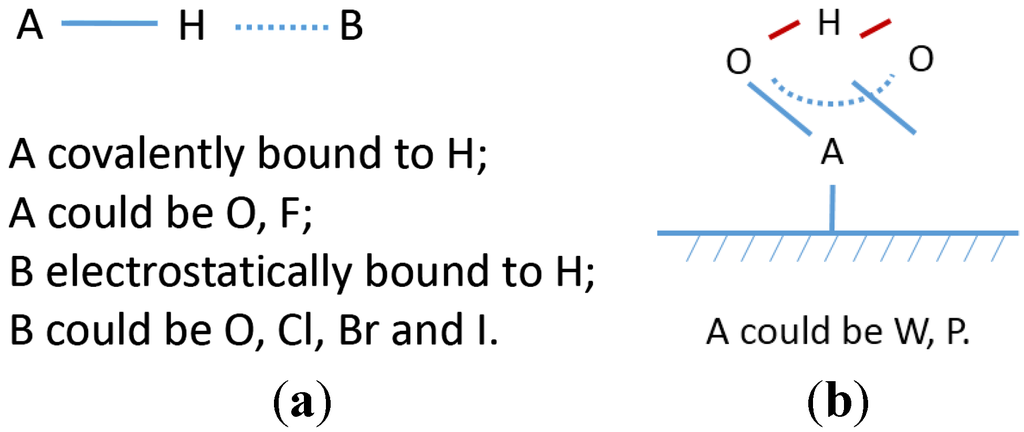
Figure 14.
(a) Hydrogen bond types in additive containing H bond type 1; and (b) H bond type 2.
3.4.2. Active Sites for Proton Transfer and H Bond Types
For traditional KOH electrolytes, the oxygen atom in the OH− group acts as the basic site to accept H from the metal hydride and transfers H between electrodes [,]. As Basak [] stated, H is covalently bonded to O with bond energy around 111 kcal·mol−1 and simultaneously has a weaker electrostatic interaction with another O with bond energy around 6–10 kcal·mol−1. This H bond type in KOH electrolytes is called H bond type 1 (shown in Figure 14a).
In this research, the anions of the additive salts, together with OH− from KOH, act as proton carriers [,,,]. For halogen containing salts, F−, Cl−, Br− and I− are basic sites for H adoption [,]. H bond type in halogen containing electrolytes can be presumed by analyzing the bond energy []. The H–F bond energy is 135 kcal·mol−1, which is higher than O–H at 111 kcal·mol−1. Thus, F should be covalently bonded to H (as the A atom in Figure 14a), and OH should be electrostatically bonded to H (as the B atom in Figure 14b). The bond energies for H–Cl, H–Br, and H–I are 103, 87.5, and 71 kcal·mol−1, respectively, which are lower than the O–H bond energy. Thus, Cl, Br, or I should be electrostatically bonded to H (as the B atom in Figure 14a), and OH covalently bonded to H (as the A atom in Figure 14a) [].
For most oxyacid salts, O is the basic site for H adsorption [,]. Analysis of the bonds containing O is important for understanding the H bond type in oxyacid salts. For CO32−, C2H3O2−, and CHO2− salts, there are two types of O containing bonds: C–O, and C=O. H is covalently bonded to C–O, and electrostatically bonded to C=O []. WO42− and PO43− are special cases regarding H bond type. There are two identical W–O bonds and two identical W=O bonds in WO42− and three identical P–O bonds in PO43−. As Basak [] stated, because of the identicality of the bonds, H is equally shared between two adjacent O by covalent interaction. In this paper, it is called H bond type 2, and its structure is as shown in Figure 14b.
3.4.3. Proton Transfer Mechanisms: Vehicle Mechanism and Structure-Diffusion Mechanism
Generally speaking, there are two kinds of proton transfer mechanisms in organic/inorganic solution systems: vehicle mechanism and structure-diffusion mechanism [,,,]. Vehicle mechanism is reported in traditional KOH electrolytes and is described as the transport of protonated species as whole molecules (for example: H2O, H3O+) through aqueous media []. In this research, proton transfer in liquid electrolyte is considered as vehicle mechanism. In addition, proton transfer through the surface solid of the electrodes, is considered as a structure-diffusion mechanism []. The proton hops from site to site along a hydrogen-bonded network over the surface. Diffusion of protonic charges or protonic defects occurs through the formation and breaking of the hydrogen bonds. Both H bond types could contribute to structure-diffusion mechanism.
The H-transfer process in additive containing electrolytes during discharge is briefly illustrated in Figure 15. The solid film over the MgNi alloy and Ni(OH)2 particles is formed during the charge process or the first few seconds of the discharge process. In the solid film covering the MgNi alloy, H is covalently or electrostatically bonded to other heteroatoms through bond type 1 or 2. H delivered through the solid film to the interface of the liquid electrolyte is through site-to-site hopping way (i.e., structure-diffusion mechanism). The H is the delivered in the electrolyte through vehicle mechanism with H bond type 1. The H bond type and H-transfer mechanism for the solid film covering the Ni(OH)2 are similar to that of the MgNi alloy. Figure 15 also illustrates the trend of the H concentration differential from the MgNi alloy to Ni(OH)2 during the discharge process. The H concentration is the highest at the metal hydride-solid film interface and the H concentration is the lowest at the Ni(OH)2-solid film interface.
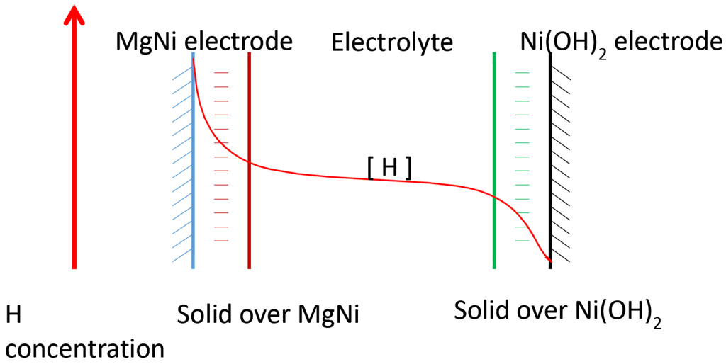
Figure 15.
Model of H-transfer from the surface of MgNi electrode to Ni(OH)2 electrode through the novel additive containing electrolyte.
3.4.4. Factors that Influence Electrochemical Performance of the Novel Additive-Containing Electrolytes
As stated before, the synergy between the additives and KOH is influenced by the nature of the salt additives. For additive containing electrolytes, both hydroxide ions and salt anions are basic sites and act as proton acceptors and carriers []. Thus, the parameters that can influence the formation of hydrogen bonds can influence the electro-performance. The parameters are summarized as follows:
- (1)
- The nature of the basic sites. The stronger the basicity, the better the performance [,]. In this research, CO32−, PO43−, and F− are strong Lewis bases and do well in decreasing degradation and boosting discharge capacity. NO3− and I− are weak Lewis bases and have poor hydrogen ion adsorption. In Figure 3, NO3− and I− containing electrolytes show poor performance.
- (2)
- The amount of basic sites. Comparing CHO2− and C2H3O2− containing electrolytes, it was found that C2H3O2− shows better performance than CHO2−. For CHO2−, the Lewis basic site that acts as the proton carrier is the oxygen in the C–O bond. For C2H3O2−, the Lewis basic sites include the oxygen in the C–O bond and the C from the CH3− group. C2H3O2− contains more basic sites than CHO2− [].
- (3)
- The stability of the salt additives. During the charge/discharge processes, the salt additives are in highly reductive/oxidative environments. The additives with low stability, such as KIO4, perform poorly.
- (4)
- The salt solubility in KOH solution. It has been found that all the SO42− containing salts have low solubility in KOH solutions [,]. The maximum solubility of K2SO4 in KOH is only around 0.093% (0.005 M). In this research, the SO42− containing electrolyte performs poorly compared to other oxyacid salt electrolytes, and similarly to pure KOH solutions.
- (5)
- The ionic charge of the additive ions. Anions with high ionic charge, such as CO32−, PO43−, WO42−, perform well.
4. Conclusions
A systematic study of 32 salt additives in a traditional KOH electrolyte was performed on an MgNi-based Ni/MH battery systems. 12 salt additives were discovered to have efficiently decreased the corrosion of traditional KOH electrolyte: NaC2H3O2, KC2H3O2, K2CO3, Rb2CO3, Cs2CO3, K3PO4, Na2WO4, Rb2SO4, Cs2SO4, NaF, KF, and KBr.
The effects of the cations (Li+, Na+, K+, Rb+, and Cs+) and anions (F−, Cl−, Br−, I−, CO32−, NO3−, PO43−, SO42−, IO4−, WO42−, C2H3O2−, and CHO2−) of the additives on charge/discharge performance were discussed. It was found that the oxidation potential of alkaline ions and the radii of halogen ions are linearly correlated with electrode degradation. For oxyacid salt electrolytes, a synergistic effect between the salt and KOH was observed: (1) a solid film forms on the MgNi particle surface, which physically prevents corrosion from KOH electrolyte and boosts discharge capacity; (2) H-transfer is promoted in aqueous electrolyte, which decreases degradation.
A brief discuss for H-transfer in the additive containing electrolyte system was included based on the screen test data. H bond type in the novel electrolyte system is not similar to traditional KOH electrolyte. Both type 1 and 2 hydrogen bonds exist in the additives containing electrolytes. Because of the formation of the solid film on the MgNi particles, the H-delivery mechanism in the novel electrolyte is also different from traditional KOH electrolytes. Both vehicle mechanism and structure-diffusion mechanism occurred in the novel electrolyte system. As the synergistic effect is determined by the nature of the salt additive, the factors that could influence the electro-performance were discussed based on the salt additive’s chemical properties including the salt’s anion’s basicity, amount of base sites, stability during charging/discharging, solubility in KOH solution, and ionic charge.
Acknowledgments
This work is financially supported by Advanced Research Projects Agency-Energy (ARPA-E) under the robust affordable next generation EV-storage (RANGE) program (DE-AR0000386).
Conflicts of Interest
The authors declare no conflict of interest.
References
- Linden, D.; Reddy, T.B. Handbook of Batteries; McGraw-Hill: New York, NY, USA, 2002. [Google Scholar]
- Fetcenko, M.A.; Ovshinsky, S.R.; Reichman, B.; Young, K.; Fierro, C.; Koch, J.; Zallen, A.; Mays, W.; Ouchi, T. Recent advances in NiMH battery technology. J. Power Sources 2007, 165, 544–551. [Google Scholar] [CrossRef]
- Iwakura, C.; Fukuda, K.; Senoh, H.; Inoue, H.; Matsuoka, M.; Yamamoto, Y. Electrochemical characterization of MmNi4.0−xMn0.75Al0.25Cox electrodes as a function of cobalt content. Electrochim. Acta 1998, 43, 2041–2046. [Google Scholar] [CrossRef]
- Geng, M.; Feng, F.; Sebastian, P.J.; Matchett, A.J.; Northwood, D.O. Charge transfer and mass transfer reactions in the metal hydride electrode. Int. J. Hydrog. Energy 2001, 26, 165–169. [Google Scholar] [CrossRef]
- Niessen, R.A.H.; Notten, R.H.L. Electrochemical hydrogen storage characteristics of thin film MgX (X = Sc, Ti, V, Cr) compounds. Electrochem. Solid State Lett. 2005, 8, 534–538. [Google Scholar] [CrossRef]
- Notten, P.H.L.; Ouwerkerk, M.; Hal, H.V.; Beelen, D.; Keur, W.; Zhou, J.; Fei, H. High energy density strategies: From hydride-forming materials research to battery integration. J. Power Sources 2004, 129, 45–54. [Google Scholar] [CrossRef]
- Young, K.; Nei, J. The current status of hydrogen storage alloy development for electrochemical applications. Materials 2013, 6, 4574–4608. [Google Scholar] [CrossRef]
- Anik, M.; Özdemir, G.; Küçükdeveci, N. Electrochemical hydrogen storage characteristics of Mg–Pd–Ni ternary alloys. Int. J. Hydrog. Energy 2011, 36, 6744–6750. [Google Scholar] [CrossRef]
- Rongeat, C.; Grosjean, M.H.; Ruggeri, S.; Dehmas, M.; Bourlot, S.; Marcotte, S.; Roué, L. Evaluation of different approaches for improving the cycle life of MgNi-based electrodes for Ni-MH batteries. J. Power Sources 2006, 158, 747–753. [Google Scholar] [CrossRef]
- Liu, J. Effect of Ti-La substitution on electrochemical properties of amorphous MgNi-based secondary hydride electrodes. J. Tianjin Norm. Univ. 2011, 313, 67–70. [Google Scholar]
- Anik, M.; Özdemir, G.; Küçükdeveci, N.; Baksan, B. Effect of Al, B, Ti and Zr additive elements on the electrochemical hydrogen storage performance of MgNi alloy. Int. J. Hydrog. Energy 2011, 36, 1568–1577. [Google Scholar] [CrossRef]
- Kalinichenka, S.; Röntzsch, L.; Riedl, T.; Gemming, T.; Weißgärber, T.; Kieback, B. Microstructure and hydrogen storage properties of melt-spun Mg–Cu–Ni–Y alloys. Int. J. Hydrog. Energy 2011, 36, 1592–1600. [Google Scholar] [CrossRef]
- Ma, F.; Liu, X.; Yan, S.; Ao, D.; Ren, Y. Research progress of influence factors on electrochemical performance of Mg-base hydrogen storage alloys. Met. Func. Mater. 2011, 34, 63–64. [Google Scholar]
- Anik, M. Effect of titanium additive element on the discharging behavior of MgNi alloy electrode. Int. J. Hydrog. Energy 2011, 36, 15075–15080. [Google Scholar] [CrossRef]
- Danczuk, M.; Nunes, C.V., Jr.; Araki, K.; Anaissi, F.J.J. Influence of Alkaline Cation on the Electrochemical Behavior of Stabilized Alpha Nickel Hydroxide. Solid State Electron. 2014, 18, 2279–2287. [Google Scholar] [CrossRef]
- Karwowska, M.; Jaron, T.; Fijalkowski, K.J.; Leszczynski, P.J.; Rogulski, Z.; Czerwinski, A. Influence of electrolyte composition and temperature on behaviour of AB5 hydrogen storage alloy used as negative electrode in Ni–MH batteries. J. Power Sources 2014, 263, 304–309. [Google Scholar] [CrossRef]
- Shangguan, E.; Li, J.; Chang, Z.; Tang, H.; Li, B.; Yuan, X.; Wang, H. Sodium tungstate as electrolyte additive to improve high-temperature performance of nickel–metal hydride batteries. Int. J. Hydrog. Energy 2013, 38, 5133–5138. [Google Scholar] [CrossRef]
- Vaidyanathan, H.; Robbins, K.; Rao, G.M. Effect of KOH concentration and anions on the performance of an Ni-H2 battery positive plate. J. Power Sources 1996, 63, 7–13. [Google Scholar] [CrossRef]
- Ovshinsky, S.R.; Fetcenko, M.A.; Reichman, B.; Young, K.; Chao, B.; Im, J. Electrochemical Hydrogen Storage Alloys and Batteries Fabricated from Mg containing Base Alloys. U.S. Patent 5,616,432, 1 April 1997. [Google Scholar]
- Schlapbach, L.; Züttel, A. Hydrogen-storage materials for mobile applications. Nature 2001, 414, 353–358. [Google Scholar] [CrossRef] [PubMed]
- Zaluska, A.; Zaluski, L.; Ström-Olsen, J.O. Structure, catalysis and atomic reactions on the nano-scale: A systematic approach to metal hydrides for hydrogen storage. Appl. Phys. A 2001, 72, 157–165. [Google Scholar] [CrossRef]
- Basak, D. Proton Transfer in Organic Scaffolds; University of Massachusetts Amherst: Amherst, MA, USA, 2012. [Google Scholar]
- Gilli, P.; Bertolasi, V.; Ferretti, V.; Gilli, G. Covalent nature of the strong homonuclear hydrogen bond—Study of the O–H---O system by crystal structure correlation methods. J. Am. Chem. Soc. 1994, 116, 909–915. [Google Scholar] [CrossRef]
- Grabowski, J.S. What is the covalency of hydrogen bonding? Chem. Rev. 2011, 111, 2597–2625. [Google Scholar] [CrossRef] [PubMed]
- Wang, B.C.; Chang, J.C.; Jiang, J.C.; Lin, S.H. Ab initio study of the ammoniated ammonium ions NH4+(NH3)0–6. Chem. Phys. 2002, 276, 93–106. [Google Scholar] [CrossRef]
© 2015 by the authors; licensee MDPI, Basel, Switzerland. This article is an open access article distributed under the terms and conditions of the Creative Commons Attribution license (http://creativecommons.org/licenses/by/4.0/).